EP3346149A1 - Bearing assembly with surface layer - Google Patents
Bearing assembly with surface layer Download PDFInfo
- Publication number
- EP3346149A1 EP3346149A1 EP18150611.4A EP18150611A EP3346149A1 EP 3346149 A1 EP3346149 A1 EP 3346149A1 EP 18150611 A EP18150611 A EP 18150611A EP 3346149 A1 EP3346149 A1 EP 3346149A1
- Authority
- EP
- European Patent Office
- Prior art keywords
- bearing
- bearing surface
- nanoparticles
- bearing assembly
- solid lubricant
- Prior art date
- Legal status (The legal status is an assumption and is not a legal conclusion. Google has not performed a legal analysis and makes no representation as to the accuracy of the status listed.)
- Granted
Links
Images

Classifications
-
- F—MECHANICAL ENGINEERING; LIGHTING; HEATING; WEAPONS; BLASTING
- F16—ENGINEERING ELEMENTS AND UNITS; GENERAL MEASURES FOR PRODUCING AND MAINTAINING EFFECTIVE FUNCTIONING OF MACHINES OR INSTALLATIONS; THERMAL INSULATION IN GENERAL
- F16C—SHAFTS; FLEXIBLE SHAFTS; ELEMENTS OR CRANKSHAFT MECHANISMS; ROTARY BODIES OTHER THAN GEARING ELEMENTS; BEARINGS
- F16C17/00—Sliding-contact bearings for exclusively rotary movement
- F16C17/10—Sliding-contact bearings for exclusively rotary movement for both radial and axial load
- F16C17/102—Sliding-contact bearings for exclusively rotary movement for both radial and axial load with grooves in the bearing surface to generate hydrodynamic pressure
-
- C—CHEMISTRY; METALLURGY
- C10—PETROLEUM, GAS OR COKE INDUSTRIES; TECHNICAL GASES CONTAINING CARBON MONOXIDE; FUELS; LUBRICANTS; PEAT
- C10M—LUBRICATING COMPOSITIONS; USE OF CHEMICAL SUBSTANCES EITHER ALONE OR AS LUBRICATING INGREDIENTS IN A LUBRICATING COMPOSITION
- C10M107/00—Lubricating compositions characterised by the base-material being a macromolecular compound
- C10M107/40—Lubricating compositions characterised by the base-material being a macromolecular compound containing nitrogen
- C10M107/44—Macromolecular compounds obtained otherwise than by reactions only involving carbon-to-carbon unsaturated bonds
-
- C—CHEMISTRY; METALLURGY
- C10—PETROLEUM, GAS OR COKE INDUSTRIES; TECHNICAL GASES CONTAINING CARBON MONOXIDE; FUELS; LUBRICANTS; PEAT
- C10M—LUBRICATING COMPOSITIONS; USE OF CHEMICAL SUBSTANCES EITHER ALONE OR AS LUBRICATING INGREDIENTS IN A LUBRICATING COMPOSITION
- C10M125/00—Lubricating compositions characterised by the additive being an inorganic material
- C10M125/02—Carbon; Graphite
-
- C—CHEMISTRY; METALLURGY
- C10—PETROLEUM, GAS OR COKE INDUSTRIES; TECHNICAL GASES CONTAINING CARBON MONOXIDE; FUELS; LUBRICANTS; PEAT
- C10M—LUBRICATING COMPOSITIONS; USE OF CHEMICAL SUBSTANCES EITHER ALONE OR AS LUBRICATING INGREDIENTS IN A LUBRICATING COMPOSITION
- C10M125/00—Lubricating compositions characterised by the additive being an inorganic material
- C10M125/22—Compounds containing sulfur, selenium or tellurium
-
- C—CHEMISTRY; METALLURGY
- C10—PETROLEUM, GAS OR COKE INDUSTRIES; TECHNICAL GASES CONTAINING CARBON MONOXIDE; FUELS; LUBRICANTS; PEAT
- C10M—LUBRICATING COMPOSITIONS; USE OF CHEMICAL SUBSTANCES EITHER ALONE OR AS LUBRICATING INGREDIENTS IN A LUBRICATING COMPOSITION
- C10M125/00—Lubricating compositions characterised by the additive being an inorganic material
- C10M125/26—Compounds containing silicon or boron, e.g. silica, sand
-
- F—MECHANICAL ENGINEERING; LIGHTING; HEATING; WEAPONS; BLASTING
- F16—ENGINEERING ELEMENTS AND UNITS; GENERAL MEASURES FOR PRODUCING AND MAINTAINING EFFECTIVE FUNCTIONING OF MACHINES OR INSTALLATIONS; THERMAL INSULATION IN GENERAL
- F16C—SHAFTS; FLEXIBLE SHAFTS; ELEMENTS OR CRANKSHAFT MECHANISMS; ROTARY BODIES OTHER THAN GEARING ELEMENTS; BEARINGS
- F16C17/00—Sliding-contact bearings for exclusively rotary movement
- F16C17/02—Sliding-contact bearings for exclusively rotary movement for radial load only
- F16C17/024—Sliding-contact bearings for exclusively rotary movement for radial load only with flexible leaves to create hydrodynamic wedge, e.g. radial foil bearings
-
- F—MECHANICAL ENGINEERING; LIGHTING; HEATING; WEAPONS; BLASTING
- F16—ENGINEERING ELEMENTS AND UNITS; GENERAL MEASURES FOR PRODUCING AND MAINTAINING EFFECTIVE FUNCTIONING OF MACHINES OR INSTALLATIONS; THERMAL INSULATION IN GENERAL
- F16C—SHAFTS; FLEXIBLE SHAFTS; ELEMENTS OR CRANKSHAFT MECHANISMS; ROTARY BODIES OTHER THAN GEARING ELEMENTS; BEARINGS
- F16C32/00—Bearings not otherwise provided for
- F16C32/06—Bearings not otherwise provided for with moving member supported by a fluid cushion formed, at least to a large extent, otherwise than by movement of the shaft, e.g. hydrostatic air-cushion bearings
- F16C32/0629—Bearings not otherwise provided for with moving member supported by a fluid cushion formed, at least to a large extent, otherwise than by movement of the shaft, e.g. hydrostatic air-cushion bearings supported by a liquid cushion, e.g. oil cushion
- F16C32/0633—Bearings not otherwise provided for with moving member supported by a fluid cushion formed, at least to a large extent, otherwise than by movement of the shaft, e.g. hydrostatic air-cushion bearings supported by a liquid cushion, e.g. oil cushion the liquid being retained in a gap
-
- F—MECHANICAL ENGINEERING; LIGHTING; HEATING; WEAPONS; BLASTING
- F16—ENGINEERING ELEMENTS AND UNITS; GENERAL MEASURES FOR PRODUCING AND MAINTAINING EFFECTIVE FUNCTIONING OF MACHINES OR INSTALLATIONS; THERMAL INSULATION IN GENERAL
- F16C—SHAFTS; FLEXIBLE SHAFTS; ELEMENTS OR CRANKSHAFT MECHANISMS; ROTARY BODIES OTHER THAN GEARING ELEMENTS; BEARINGS
- F16C33/00—Parts of bearings; Special methods for making bearings or parts thereof
- F16C33/02—Parts of sliding-contact bearings
- F16C33/04—Brasses; Bushes; Linings
- F16C33/06—Sliding surface mainly made of metal
- F16C33/10—Construction relative to lubrication
- F16C33/1025—Construction relative to lubrication with liquid, e.g. oil, as lubricant
- F16C33/106—Details of distribution or circulation inside the bearings, e.g. details of the bearing surfaces to affect flow or pressure of the liquid
- F16C33/107—Grooves for generating pressure
-
- F—MECHANICAL ENGINEERING; LIGHTING; HEATING; WEAPONS; BLASTING
- F16—ENGINEERING ELEMENTS AND UNITS; GENERAL MEASURES FOR PRODUCING AND MAINTAINING EFFECTIVE FUNCTIONING OF MACHINES OR INSTALLATIONS; THERMAL INSULATION IN GENERAL
- F16C—SHAFTS; FLEXIBLE SHAFTS; ELEMENTS OR CRANKSHAFT MECHANISMS; ROTARY BODIES OTHER THAN GEARING ELEMENTS; BEARINGS
- F16C33/00—Parts of bearings; Special methods for making bearings or parts thereof
- F16C33/02—Parts of sliding-contact bearings
- F16C33/04—Brasses; Bushes; Linings
- F16C33/06—Sliding surface mainly made of metal
- F16C33/10—Construction relative to lubrication
- F16C33/1095—Construction relative to lubrication with solids as lubricant, e.g. dry coatings, powder
-
- C—CHEMISTRY; METALLURGY
- C10—PETROLEUM, GAS OR COKE INDUSTRIES; TECHNICAL GASES CONTAINING CARBON MONOXIDE; FUELS; LUBRICANTS; PEAT
- C10M—LUBRICATING COMPOSITIONS; USE OF CHEMICAL SUBSTANCES EITHER ALONE OR AS LUBRICATING INGREDIENTS IN A LUBRICATING COMPOSITION
- C10M2201/00—Inorganic compounds or elements as ingredients in lubricant compositions
- C10M2201/04—Elements
- C10M2201/041—Carbon; Graphite; Carbon black
-
- C—CHEMISTRY; METALLURGY
- C10—PETROLEUM, GAS OR COKE INDUSTRIES; TECHNICAL GASES CONTAINING CARBON MONOXIDE; FUELS; LUBRICANTS; PEAT
- C10M—LUBRICATING COMPOSITIONS; USE OF CHEMICAL SUBSTANCES EITHER ALONE OR AS LUBRICATING INGREDIENTS IN A LUBRICATING COMPOSITION
- C10M2201/00—Inorganic compounds or elements as ingredients in lubricant compositions
- C10M2201/04—Elements
- C10M2201/041—Carbon; Graphite; Carbon black
- C10M2201/0413—Carbon; Graphite; Carbon black used as base material
-
- C—CHEMISTRY; METALLURGY
- C10—PETROLEUM, GAS OR COKE INDUSTRIES; TECHNICAL GASES CONTAINING CARBON MONOXIDE; FUELS; LUBRICANTS; PEAT
- C10M—LUBRICATING COMPOSITIONS; USE OF CHEMICAL SUBSTANCES EITHER ALONE OR AS LUBRICATING INGREDIENTS IN A LUBRICATING COMPOSITION
- C10M2201/00—Inorganic compounds or elements as ingredients in lubricant compositions
- C10M2201/06—Metal compounds
- C10M2201/061—Carbides; Hydrides; Nitrides
- C10M2201/0613—Carbides; Hydrides; Nitrides used as base material
-
- C—CHEMISTRY; METALLURGY
- C10—PETROLEUM, GAS OR COKE INDUSTRIES; TECHNICAL GASES CONTAINING CARBON MONOXIDE; FUELS; LUBRICANTS; PEAT
- C10M—LUBRICATING COMPOSITIONS; USE OF CHEMICAL SUBSTANCES EITHER ALONE OR AS LUBRICATING INGREDIENTS IN A LUBRICATING COMPOSITION
- C10M2201/00—Inorganic compounds or elements as ingredients in lubricant compositions
- C10M2201/06—Metal compounds
- C10M2201/062—Oxides; Hydroxides; Carbonates or bicarbonates
- C10M2201/0623—Oxides; Hydroxides; Carbonates or bicarbonates used as base material
-
- C—CHEMISTRY; METALLURGY
- C10—PETROLEUM, GAS OR COKE INDUSTRIES; TECHNICAL GASES CONTAINING CARBON MONOXIDE; FUELS; LUBRICANTS; PEAT
- C10M—LUBRICATING COMPOSITIONS; USE OF CHEMICAL SUBSTANCES EITHER ALONE OR AS LUBRICATING INGREDIENTS IN A LUBRICATING COMPOSITION
- C10M2201/00—Inorganic compounds or elements as ingredients in lubricant compositions
- C10M2201/06—Metal compounds
- C10M2201/065—Sulfides; Selenides; Tellurides
- C10M2201/066—Molybdenum sulfide
-
- C—CHEMISTRY; METALLURGY
- C10—PETROLEUM, GAS OR COKE INDUSTRIES; TECHNICAL GASES CONTAINING CARBON MONOXIDE; FUELS; LUBRICANTS; PEAT
- C10M—LUBRICATING COMPOSITIONS; USE OF CHEMICAL SUBSTANCES EITHER ALONE OR AS LUBRICATING INGREDIENTS IN A LUBRICATING COMPOSITION
- C10M2201/00—Inorganic compounds or elements as ingredients in lubricant compositions
- C10M2201/087—Boron oxides, acids or salts
-
- C—CHEMISTRY; METALLURGY
- C10—PETROLEUM, GAS OR COKE INDUSTRIES; TECHNICAL GASES CONTAINING CARBON MONOXIDE; FUELS; LUBRICANTS; PEAT
- C10M—LUBRICATING COMPOSITIONS; USE OF CHEMICAL SUBSTANCES EITHER ALONE OR AS LUBRICATING INGREDIENTS IN A LUBRICATING COMPOSITION
- C10M2217/00—Organic macromolecular compounds containing nitrogen as ingredients in lubricant compositions
- C10M2217/04—Macromolecular compounds from nitrogen-containing monomers obtained otherwise than by reactions only involving carbon-to-carbon unsaturated bonds
- C10M2217/044—Polyamides
- C10M2217/0443—Polyamides used as base material
-
- C—CHEMISTRY; METALLURGY
- C10—PETROLEUM, GAS OR COKE INDUSTRIES; TECHNICAL GASES CONTAINING CARBON MONOXIDE; FUELS; LUBRICANTS; PEAT
- C10N—INDEXING SCHEME ASSOCIATED WITH SUBCLASS C10M RELATING TO LUBRICATING COMPOSITIONS
- C10N2020/00—Specified physical or chemical properties or characteristics, i.e. function, of component of lubricating compositions
- C10N2020/01—Physico-chemical properties
- C10N2020/055—Particles related characteristics
- C10N2020/06—Particles of special shape or size
-
- C—CHEMISTRY; METALLURGY
- C10—PETROLEUM, GAS OR COKE INDUSTRIES; TECHNICAL GASES CONTAINING CARBON MONOXIDE; FUELS; LUBRICANTS; PEAT
- C10N—INDEXING SCHEME ASSOCIATED WITH SUBCLASS C10M RELATING TO LUBRICATING COMPOSITIONS
- C10N2040/00—Specified use or application for which the lubricating composition is intended
- C10N2040/02—Bearings
-
- C—CHEMISTRY; METALLURGY
- C10—PETROLEUM, GAS OR COKE INDUSTRIES; TECHNICAL GASES CONTAINING CARBON MONOXIDE; FUELS; LUBRICANTS; PEAT
- C10N—INDEXING SCHEME ASSOCIATED WITH SUBCLASS C10M RELATING TO LUBRICATING COMPOSITIONS
- C10N2050/00—Form in which the lubricant is applied to the material being lubricated
- C10N2050/08—Solids
-
- F—MECHANICAL ENGINEERING; LIGHTING; HEATING; WEAPONS; BLASTING
- F16—ENGINEERING ELEMENTS AND UNITS; GENERAL MEASURES FOR PRODUCING AND MAINTAINING EFFECTIVE FUNCTIONING OF MACHINES OR INSTALLATIONS; THERMAL INSULATION IN GENERAL
- F16C—SHAFTS; FLEXIBLE SHAFTS; ELEMENTS OR CRANKSHAFT MECHANISMS; ROTARY BODIES OTHER THAN GEARING ELEMENTS; BEARINGS
- F16C2240/00—Specified values or numerical ranges of parameters; Relations between them
- F16C2240/40—Linear dimensions, e.g. length, radius, thickness, gap
- F16C2240/48—Particle sizes
Definitions
- Bearing assemblies are widely used to provide engagement between a moving component or assembly (i.e., a rotor) and a support or other structure that is stationary or that moves at a different speed than the moving component or assembly.
- a moving component or assembly i.e., a rotor
- One challenge faced by bearing assemblies is management of friction between the moving and non-moving components or between components moving at different speeds.
- Many bearing assemblies utilize one or more rolling surfaces such as balls or other rollers disposed in a raceway formed by race structures integrated with or attached to the rotor and the support.
- Other bearing assemblies rely on low-friction sliding surfaces for engagement between the rotor and support.
- Another type of bearing assembly relies on the presence of a fluid between the bearing surfaces to maintain the bearing surfaces in a non-contact relationship.
- the fluid can be a liquid or a gas, with the gas often provided under pressure sufficient to maintain the bearing surfaces in a non-contact relationship.
- the fluid between the bearing surfaces is pressurized air, and such bearings are commonly referred to as "air bearings".
- Non-contact bearing assemblies such as air bearings can provide effective management of significant frictional forces to the bearing surfaces.
- friction on the bearing surfaces is not necessarily eliminated for all operational conditions.
- any interruption of the pressurized fluid source can subject the bearing surfaces to frictional contact.
- non-standard operating conditions such as an overload on the bearing assembly can overwhelm the fluid buffer and force the components into frictional contact.
- aerodynamic or hydrodynamic bearings that rely on the motion of the bearing components themselves or on connected components to generate or pressurize the fluid buffer, the bearing surfaces can come into frictional contact during commencement or termination of the components' motion (i.e., startup or shutdown).
- a bearing assembly comprises a first component comprising a first bearing surface, and a second component comprising a second bearing surface.
- a fluid is disposed between the first bearing surface and the second bearing surface supporting the first bearing surface and the second bearing surface in a non-contact rotational relationship.
- the first bearing surface, or the second bearing surface, or both the first bearing surface and the second bearing surface include a surface layer comprising solid lubricant 2D nanoparticles in a matrix.
- a bearing comprises a support, a bump foil over the support, a top foil over the bump foil, and a surface layer over the bump foil comprising solid lubricant 2D nanoparticles in a matrix.
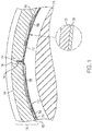
- FIG. 1 is a cross-sectional view of an example embodiment of a fluid film journal bearing assembly (journal bearing 100).
- the journal bearing 100 includes a journal sleeve 102 that defines an outer diameter surface 104 and an inner diameter surface 106.
- the journal sleeve 102 is substantially cylindrical and is arranged about a central axis. It should be noted that the journal sleeve can have a conventional cylindrical shape, or can be shaped with a weight-reduced profile, or configured as other shapes or configurations, and FIG. 1 merely presents an exemplary configuration of a journal bearing 100.
- the journal bearing 100 includes a bump foil 108, an intermediate foil 110, and a top foil 112.
- the bump foil 108, the intermediate foil 110, and the top foil 112 are each formed from thin sheets of material (e.g., nickel-based alloys, steel, or similar materials) wrapped in a generally cylindrical shape and positioned in a bore of the journal sleeve 102.
- the bump foil 108 is corrugated, allowing a working fluid and/or cooling fluid to flow through the spaces formed between adjacent corrugations.
- the bump foil 108 is positioned adjacent to the inner diameter surface 106 of the journal sleeve 102.
- the foils 108, 110, and 112 are retained relative to the journal sleeve 102 with bent portions 114 that engage a key slot 116.
- a rotating component 118 such as a shaft can be positioned inside the journal bearing 100, radially inward from the top foil 112.
- the rotating component 118 is typically in close proximity to the top foil 112, but for ease of illustration is shown in a partial exploded view with an exaggerated distance between the top foil 112 and the rotating component 118.
- moving air generated by action of the rotating component 118 urges pressurized air radially outward against the compliant foil structure 108, 110, and 112 to create a fluid air layer separating the rotating component 118 and the journal bearing 100.
- a surface layer 120 which is exposed to a bearing surface of a rotating component, is disposed over (in this case, radially inward from) the top foil 112.
- the surface layer 120 comprises solid lubricant 2D nanoparticles in a matrix.
- the surface layer can have a thickness in a range with a low end of 2 nm, 8, nm, or 12 nm, and a high end of 65 nm, 40 nm, or 20 nm. All possible combinations of the above-mentioned range endpoints (excluding impossible combinations where a low endpoint would have a greater value than a high endpoint) are explicitly included herein as disclosed ranges.
- the surface layers discussed herein can be included as a surface layer on either or both of the bearing surfaces of relative motion.
- the surface layer can be on the surface of the bearing surface on the radially inner surface of top foil 112 as shown for surface layer 120 in FIG. 1 , or the surface layer can be on the radially outer surface of the rotating member 118, or the surface layer can be on the surface of the bearing surface on the radially inner surface of top foil 112 as shown for surface layer 120 in FIG. 1 and on the radially outer surface of the rotating member 118.
- the matrix of a surface layer can include any sort of matrix material, including but not limited to polymers, ceramics, metal, or matrix materials that can form a continuous phase.
- the matrix material comprises a polyamide polymer, a polyimide polymer, or a copolymer comprising polyamide or polyimide segments.
- the matrix material comprises a polyamide-polyimide copolymer.
- Various application techniques for creation or application of the surface layer can be utilized by the skilled person. For example, a surface layer can be applied as a polymer coating by spray application of a liquid or powder coating composition comprising a polymer matrix material and dispersed solid lubricant 2D nanoparticles followed by curing to coalesce and solidify the coating.
- the solid lubricant 2D nanoparticles are present in the surface layer at a concentration in a range with a low end of 35 wt.%, 45 wt.%, or 58 wt.%, and a high end of 72 wt.%, 68 wt.%, or 62 wt.%, based on the total coating solids. All possible combinations of the above-mentioned range endpoints (excluding impossible combinations where a low endpoint would have a greater value than a high endpoint) are explicitly included herein as disclosed ranges.
- the surface layer can also include various other materials.
- the surface layer can include various polymer coating additives (e.g., curing agents, antioxidants, coating aids, fillers, etc.).
- the term "2D” includes particles with a smallest dimension, or thickness, of 1 to 20 molecular layers, and one or more anisotropic dimensions along lines or planes that diverge from the thickness. In some embodiments, the anisotropic dimensions can extend beyond 100 nm, although this is not necessary.
- the 2D nanoparticles can have an aspect ratio, defined as the ratio of the largest dimension to the smallest dimension of at least 10. In some embodiments, the 2D nanoparticles can have an aspect ratio, defined as the ratio of the largest dimension to the smallest dimension of at least 100.
- the 2D nanoparticles can have an even higher aspect ratio of at least 2500. Higher levels of aspect ratios can be obtained at relatively complete levels of exfoliation, including to the level of a single molecular layer.
- the 2D nanoparticles can have a thickness ranging from 1 to 20 molecular layers. In some embodiments, the 2D nanoparticles can have a thickness ranging from 1 to 15 molecular layers. In some embodiments, the 2D nanoparticles can have a thickness ranging from 1 to 10 molecular layers. In some embodiments, the 2D nanoparticles can have a thickness ranging from 1 to 5 molecular layers.
- the 2D nanoparticles can have a thickness ranging from 1 to 4 molecular layers. In some embodiments, the 2D nanoparticles can have a thickness ranging from 1 to 3 molecular layers. In some embodiments, the 2D nanoparticles can have a thickness ranging from 1 to 2 molecular layers. In some embodiments, the 2D nanoparticles can have a thickness of 1 molecular layer. In some embodiments, the 2D nanoparticles can have a have a mean diameter in a range with a low end of 10 nm, 90 nm, or 1 ⁇ m, and a high end of 13 ⁇ m, 7 ⁇ m, or 5 ⁇ m.
- Mean diameter for 2D nanoparticles can be determined using commercially available electron microscopy measurement tools. All possible combinations of the above-mentioned range endpoints (excluding impossible combinations where a low endpoint would have a greater value than a high endpoint) are explicitly included herein as disclosed ranges.
- lubricant is used herein with respect to the solid 2D nanoparticles, the solid 2D nanoparticles are considered as "lubricant” nanoparticles if the coating has a coefficient of friction that is less than a coefficient of friction of a comparison coating of the same matrix material but without the solid 2D nanoparticles.
- the surface layer can include lubricant materials in addition to the solid lubricant 2D nanoparticles.
- additional solid lubricant particles or nanoparticles include particles or nanoparticles of materials such as graphene, hexagonal boron nitride, or hexagonal molybdenum disulfide of different particle sizes than the solid lubricant 2D nanoparticles.
- Solid 2D nanoparticles can be prepared by various techniques.
- Graphene for example, can be prepared by different techniques including chemical vapor deposition onto a substrate up to a target thickness followed by removal of graphene from the substrate.
- Solid 2D nanoparticles including graphene, hexagonal boron nitride, and hexagonal molybdenum disulfide, can also be prepared by exfoliation of a parent molecular three-dimensional material such as graphite, unexfoliated hexagonal boron nitride, or unexfoliated hexaganol molybdenum disulfide.
- Various exfoliation techniques can be used, including mechanical exfoliation, sonic exfoliation, thermal exfoliation, or chemical exfoliation.
- Many exfoliation techniques can be controlled (e.g., by controlling duration, reaction conditions such as agitation speed or temperature, or materials, or both duration and reaction conditions or materials) to produce solid 2D nanoparticles with particle size and configuration in a target range
- FIG. 1 is just one of many possible example embodiments.
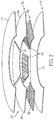
- FIG. 2 Another example embodiment is shown in FIG. 2 , in which an exploded view is shown of an example embodiment of a hydrodynamic fluid film thrust bearing assembly ("thrust bearing 200"), which represents another type of foil hydrodynamic bearing.
- the thrust bearing 200 of FIG. 2 has a different construction than the journal bearing 100 of FIG. 1 . This is because journal bearings, such as shown in FIG. 1 , operate with radial loads, whereas thrust bearings, as shown in FIG. 2 , operate with axial loads.
- both types of bearings operate similarly by employing hydrodynamic fluid films, such as air or other fluids, to both provide bearing lubricant and cooling.
- the thrust bearing 200 includes three layers, but may include more or fewer layers.
- a first layer 202 comprises multiple arcuate top foils 204 that are spaced circumferentially relative to one another about a central axis.
- the top foils 204 are supported by a second layer 206 having a corresponding number of arcuate bump foils 208 arranged circumferentially beneath the top foils 204.
- the bump foils 208 are corrugated to provide cushioning and accommodate a cooling airflow through the thrust bearing 200.
- a third layer 210 is provided as an annular main plate 212 that supports the bump foils 208.
- the three layers 202, 206, and 210 can be secured to one another, for example, by spot welding.
- a rotating component 214 such as a thrust plate on an end of a rotating shaft can be positioned adjacent to the top foils 204.
- the rotating component 214 is typically in close proximity to the top foils 204, but for ease of illustration is shown in a partial exploded view with an exaggerated distance between the top foil 204 and the rotating component 214.
- moving air generated by action of the rotating component 214 urges pressurized air against the compliant foil structure to create a fluid air layer separating the rotating component 214 and the thrust bearing 200.
- the surface layer (not shown) can be on the surface of the bearing surface on the radially inner surface of top foil 204, or the surface layer can be on the radially outer surface of the rotating component 214, or the surface layer can be on the surface of the bearing surface on the radially inner surface of top foil 204 and on the radially outer surface of the rotating component 214.
- the above described hydrodynamic bearings can be employed in an air cycle machine such as those employed on aircraft.
- the hydrodynamic bearings provide a long lasting bearing with minimal to no required maintenance. This is because the bearings employ air as both a lubricating fluid and as a cooling fluid, which means that separate lubricating or cooling liquids are not typically required.
- An example embodiment of an air cycle machine is shown in FIG. 3 .
- an air cycle machine 300 is part of an environmental control system that is configured to supply conditioned air, for example, to a cabin of an aircraft.
- the air cycle machine 300 is a four-wheel air cycle machine, with four rotors on a single shaft 304. The four rotors are fixed together and are supported by bearing elements.
- the air flow passage 306 provides air as both a lubricating fluid for the hydrodynamic bearings and as a cooling air flow to remove heat generated by the bearings during operation.
- two of the four bearings are thrust bearings and two are journal bearings, as described above.
- the thrust bearings are located at the inlet side of the airflow passage 306, with the journal bearings located further downstream in the airflow passage 306.
- a first thrust bearing 308 is configured as an outboard thrust bearing and a second thrust bearing 310 is configured as an inboard thrust bearing.
- a first journal bearing 312 is configured as a turbine journal bearing and then, toward the outlet of the airflow passage 306, a second journal bearing 314 is configured as a fan journal bearing.
- the thrust bearings 308 and 310 are configured to operate with axial loads, and the journal bearings 312 and 314 are configured to operate with radial loads within the engine 302.
- the air cycle machine 300 may operate at 20,000-50,000 RPM. However, other rotational speeds of operation may be used.
Landscapes
- Chemical & Material Sciences (AREA)
- Engineering & Computer Science (AREA)
- General Engineering & Computer Science (AREA)
- Mechanical Engineering (AREA)
- Oil, Petroleum & Natural Gas (AREA)
- Chemical Kinetics & Catalysis (AREA)
- General Chemical & Material Sciences (AREA)
- Organic Chemistry (AREA)
- Inorganic Chemistry (AREA)
- Physics & Mathematics (AREA)
- Fluid Mechanics (AREA)
- Sliding-Contact Bearings (AREA)
Abstract
Description
- Bearing assemblies are widely used to provide engagement between a moving component or assembly (i.e., a rotor) and a support or other structure that is stationary or that moves at a different speed than the moving component or assembly. One challenge faced by bearing assemblies is management of friction between the moving and non-moving components or between components moving at different speeds. Many bearing assemblies utilize one or more rolling surfaces such as balls or other rollers disposed in a raceway formed by race structures integrated with or attached to the rotor and the support. Other bearing assemblies rely on low-friction sliding surfaces for engagement between the rotor and support. Another type of bearing assembly relies on the presence of a fluid between the bearing surfaces to maintain the bearing surfaces in a non-contact relationship. The fluid can be a liquid or a gas, with the gas often provided under pressure sufficient to maintain the bearing surfaces in a non-contact relationship. In many cases, the fluid between the bearing surfaces is pressurized air, and such bearings are commonly referred to as "air bearings".
- Non-contact bearing assemblies such as air bearings can provide effective management of significant frictional forces to the bearing surfaces. However, friction on the bearing surfaces is not necessarily eliminated for all operational conditions. For example, in the case of pressurized air supplied to an aerostatic or hydrostatic bearing, any interruption of the pressurized fluid source can subject the bearing surfaces to frictional contact. Also, non-standard operating conditions such as an overload on the bearing assembly can overwhelm the fluid buffer and force the components into frictional contact. In the case of aerodynamic or hydrodynamic bearings that rely on the motion of the bearing components themselves or on connected components to generate or pressurize the fluid buffer, the bearing surfaces can come into frictional contact during commencement or termination of the components' motion (i.e., startup or shutdown).
- In some embodiments of this disclosure, a bearing assembly comprises a first component comprising a first bearing surface, and a second component comprising a second bearing surface. A fluid is disposed between the first bearing surface and the second bearing surface supporting the first bearing surface and the second bearing surface in a non-contact rotational relationship. The first bearing surface, or the second bearing surface, or both the first bearing surface and the second bearing surface include a surface layer comprising solid lubricant 2D nanoparticles in a matrix.
- In some embodiments, a bearing comprises a support, a bump foil over the support, a top foil over the bump foil, and a surface layer over the bump foil comprising solid lubricant 2D nanoparticles in a matrix.
- Subject matter of this disclosure is particularly pointed out and distinctly claimed in the claims at the conclusion of the specification. The foregoing and other features, and advantages of the present disclosure are apparent from the following detailed description taken in conjunction with the accompanying drawings in which:
-
FIG. 1 is a partial cross-sectional view of an example embodiment of a journal bearing; -
FIG. 2 is a partial exploded view of an example embodiment thrust bearing; and -
FIG. 3 is a schematic cross-sectional view of an air cycle machine. - With reference now to the Figures,
FIG. 1 is a cross-sectional view of an example embodiment of a fluid film journal bearing assembly (journal bearing 100). The journal bearing 100 includes ajournal sleeve 102 that defines anouter diameter surface 104 and aninner diameter surface 106. Thejournal sleeve 102 is substantially cylindrical and is arranged about a central axis. It should be noted that the journal sleeve can have a conventional cylindrical shape, or can be shaped with a weight-reduced profile, or configured as other shapes or configurations, andFIG. 1 merely presents an exemplary configuration of a journal bearing 100. - In
FIG. 1 , a number of foils are arranged inside thejournal sleeve 102. The journal bearing 100 includes abump foil 108, anintermediate foil 110, and atop foil 112. Thebump foil 108, theintermediate foil 110, and thetop foil 112 are each formed from thin sheets of material (e.g., nickel-based alloys, steel, or similar materials) wrapped in a generally cylindrical shape and positioned in a bore of thejournal sleeve 102. Thebump foil 108 is corrugated, allowing a working fluid and/or cooling fluid to flow through the spaces formed between adjacent corrugations. Thebump foil 108 is positioned adjacent to theinner diameter surface 106 of thejournal sleeve 102. Thefoils journal sleeve 102 withbent portions 114 that engage akey slot 116. A rotatingcomponent 118, such as a shaft can be positioned inside the journal bearing 100, radially inward from thetop foil 112. The rotatingcomponent 118 is typically in close proximity to thetop foil 112, but for ease of illustration is shown in a partial exploded view with an exaggerated distance between thetop foil 112 and therotating component 118. During operation, moving air generated by action of the rotatingcomponent 118 urges pressurized air radially outward against thecompliant foil structure rotating component 118 and the journal bearing 100. - As further shown in
FIG. 1 , asurface layer 120, which is exposed to a bearing surface of a rotating component, is disposed over (in this case, radially inward from) thetop foil 112. Thesurface layer 120 comprises solid lubricant 2D nanoparticles in a matrix. In some embodiments, the surface layer can have a thickness in a range with a low end of 2 nm, 8, nm, or 12 nm, and a high end of 65 nm, 40 nm, or 20 nm. All possible combinations of the above-mentioned range endpoints (excluding impossible combinations where a low endpoint would have a greater value than a high endpoint) are explicitly included herein as disclosed ranges. The surface layers discussed herein can be included as a surface layer on either or both of the bearing surfaces of relative motion. For example, in the case of the example embodiment such asFIG. 1 showing a bearing assembly comprising a rotatingmember 118 and a journal bearing 100, the surface layer can be on the surface of the bearing surface on the radially inner surface oftop foil 112 as shown forsurface layer 120 inFIG. 1 , or the surface layer can be on the radially outer surface of the rotatingmember 118, or the surface layer can be on the surface of the bearing surface on the radially inner surface oftop foil 112 as shown forsurface layer 120 inFIG. 1 and on the radially outer surface of the rotatingmember 118. - The matrix of a surface layer such as
surface layer 120 can include any sort of matrix material, including but not limited to polymers, ceramics, metal, or matrix materials that can form a continuous phase. In some embodiments, the matrix material comprises a polyamide polymer, a polyimide polymer, or a copolymer comprising polyamide or polyimide segments. In some embodiments, the matrix material comprises a polyamide-polyimide copolymer. Various application techniques for creation or application of the surface layer can be utilized by the skilled person. For example, a surface layer can be applied as a polymer coating by spray application of a liquid or powder coating composition comprising a polymer matrix material and dispersed solid lubricant 2D nanoparticles followed by curing to coalesce and solidify the coating. In some embodiments, the solid lubricant 2D nanoparticles are present in the surface layer at a concentration in a range with a low end of 35 wt.%, 45 wt.%, or 58 wt.%, and a high end of 72 wt.%, 68 wt.%, or 62 wt.%, based on the total coating solids. All possible combinations of the above-mentioned range endpoints (excluding impossible combinations where a low endpoint would have a greater value than a high endpoint) are explicitly included herein as disclosed ranges. The surface layer can also include various other materials. For example, in the case of polymer coatings, the surface layer can include various polymer coating additives (e.g., curing agents, antioxidants, coating aids, fillers, etc.). - Various materials can be utilized as solid lubricant 2D nanoparticles. As used herein, the term "2D" includes particles with a smallest dimension, or thickness, of 1 to 20 molecular layers, and one or more anisotropic dimensions along lines or planes that diverge from the thickness. In some embodiments, the anisotropic dimensions can extend beyond 100 nm, although this is not necessary. In some embodiments, the 2D nanoparticles can have an aspect ratio, defined as the ratio of the largest dimension to the smallest dimension of at least 10. In some embodiments, the 2D nanoparticles can have an aspect ratio, defined as the ratio of the largest dimension to the smallest dimension of at least 100. In some embodiments, the 2D nanoparticles can have an even higher aspect ratio of at least 2500. Higher levels of aspect ratios can be obtained at relatively complete levels of exfoliation, including to the level of a single molecular layer. As mentioned above, the 2D nanoparticles can have a thickness ranging from 1 to 20 molecular layers. In some embodiments, the 2D nanoparticles can have a thickness ranging from 1 to 15 molecular layers. In some embodiments, the 2D nanoparticles can have a thickness ranging from 1 to 10 molecular layers. In some embodiments, the 2D nanoparticles can have a thickness ranging from 1 to 5 molecular layers. In some embodiments, the 2D nanoparticles can have a thickness ranging from 1 to 4 molecular layers. In some embodiments, the 2D nanoparticles can have a thickness ranging from 1 to 3 molecular layers. In some embodiments, the 2D nanoparticles can have a thickness ranging from 1 to 2 molecular layers. In some embodiments, the 2D nanoparticles can have a thickness of 1 molecular layer. In some embodiments, the 2D nanoparticles can have a have a mean diameter in a range with a low end of 10 nm, 90 nm, or 1 µm, and a high end of 13 µm, 7µm, or 5 µm. Mean diameter for 2D nanoparticles can be determined using commercially available electron microscopy measurement tools. All possible combinations of the above-mentioned range endpoints (excluding impossible combinations where a low endpoint would have a greater value than a high endpoint) are explicitly included herein as disclosed ranges. As the term "lubricant" is used herein with respect to the solid 2D nanoparticles, the solid 2D nanoparticles are considered as "lubricant" nanoparticles if the coating has a coefficient of friction that is less than a coefficient of friction of a comparison coating of the same matrix material but without the solid 2D nanoparticles. Examples of materials for the solid lubricant 2D nanoparticles include graphene, hexagonal boron nitride, or molybdenum disulfide. In some embodiments, the surface layer can include lubricant materials in addition to the solid lubricant 2D nanoparticles. Examples of such additional solid lubricant particles or nanoparticles include particles or nanoparticles of materials such as graphene, hexagonal boron nitride, or hexagonal molybdenum disulfide of different particle sizes than the solid lubricant 2D nanoparticles.
- Solid 2D nanoparticles can be prepared by various techniques. Graphene, for example, can be prepared by different techniques including chemical vapor deposition onto a substrate up to a target thickness followed by removal of graphene from the substrate. Solid 2D nanoparticles, including graphene, hexagonal boron nitride, and hexagonal molybdenum disulfide, can also be prepared by exfoliation of a parent molecular three-dimensional material such as graphite, unexfoliated hexagonal boron nitride, or unexfoliated hexaganol molybdenum disulfide. Various exfoliation techniques can be used, including mechanical exfoliation, sonic exfoliation, thermal exfoliation, or chemical exfoliation. Many exfoliation techniques can be controlled (e.g., by controlling duration, reaction conditions such as agitation speed or temperature, or materials, or both duration and reaction conditions or materials) to produce solid 2D nanoparticles with particle size and configuration in a target range.
- The bearing assembly shown in
FIG. 1 is just one of many possible example embodiments. Another example embodiment is shown inFIG. 2 , in which an exploded view is shown of an example embodiment of a hydrodynamic fluid film thrust bearing assembly ("thrust bearing 200"), which represents another type of foil hydrodynamic bearing. As is apparent from the Figures, the thrust bearing 200 ofFIG. 2 has a different construction than the journal bearing 100 ofFIG. 1 . This is because journal bearings, such as shown inFIG. 1 , operate with radial loads, whereas thrust bearings, as shown inFIG. 2 , operate with axial loads. However, both types of bearings operate similarly by employing hydrodynamic fluid films, such as air or other fluids, to both provide bearing lubricant and cooling. - In the example embodiment of
FIG. 2 , thethrust bearing 200 includes three layers, but may include more or fewer layers. Afirst layer 202 comprises multiple arcuate top foils 204 that are spaced circumferentially relative to one another about a central axis. The top foils 204 are supported by asecond layer 206 having a corresponding number of arcuate bump foils 208 arranged circumferentially beneath the top foils 204. The bump foils 208 are corrugated to provide cushioning and accommodate a cooling airflow through thethrust bearing 200. Athird layer 210 is provided as an annularmain plate 212 that supports the bump foils 208. The threelayers rotating component 214, such as a thrust plate on an end of a rotating shaft can be positioned adjacent to the top foils 204. Therotating component 214 is typically in close proximity to the top foils 204, but for ease of illustration is shown in a partial exploded view with an exaggerated distance between thetop foil 204 and therotating component 214. During operation, moving air generated by action of therotating component 214 urges pressurized air against the compliant foil structure to create a fluid air layer separating therotating component 214 and thethrust bearing 200. As with the journal bearing 100 ofFIG. 1 , the surface layer (not shown) can be on the surface of the bearing surface on the radially inner surface oftop foil 204, or the surface layer can be on the radially outer surface of therotating component 214, or the surface layer can be on the surface of the bearing surface on the radially inner surface oftop foil 204 and on the radially outer surface of therotating component 214. - In some embodiments, the above described hydrodynamic bearings can be employed in an air cycle machine such as those employed on aircraft. The hydrodynamic bearings provide a long lasting bearing with minimal to no required maintenance. This is because the bearings employ air as both a lubricating fluid and as a cooling fluid, which means that separate lubricating or cooling liquids are not typically required. An example embodiment of an air cycle machine is shown in
FIG. 3 . As shown inFIG. 3 , anair cycle machine 300 is part of an environmental control system that is configured to supply conditioned air, for example, to a cabin of an aircraft. Theair cycle machine 300 is a four-wheel air cycle machine, with four rotors on asingle shaft 304. The four rotors are fixed together and are supported by bearing elements. There are, thus, four bearings configured within theair cycle machine 300 which are arranged along anairflow passage 306, which is represented by the path of arrows inFIG. 3 . Theair flow passage 306 provides air as both a lubricating fluid for the hydrodynamic bearings and as a cooling air flow to remove heat generated by the bearings during operation. - In the example configuration of
FIG. 3 , two of the four bearings are thrust bearings and two are journal bearings, as described above. The thrust bearings are located at the inlet side of theairflow passage 306, with the journal bearings located further downstream in theairflow passage 306. A first thrust bearing 308 is configured as an outboard thrust bearing and a second thrust bearing 310 is configured as an inboard thrust bearing. After thethrust bearings airflow passage 306, a first journal bearing 312 is configured as a turbine journal bearing and then, toward the outlet of theairflow passage 306, a second journal bearing 314 is configured as a fan journal bearing. Thethrust bearings journal bearings engine 302. As a nonlimiting example, theair cycle machine 300 may operate at 20,000-50,000 RPM. However, other rotational speeds of operation may be used. - While the present disclosure has been described in detail in connection with only a limited number of embodiments, it should be readily understood that the present disclosure is not limited to such disclosed embodiments. Rather, the present disclosure can be modified to incorporate any number of variations, alterations, substitutions or equivalent arrangements not heretofore described, but which are commensurate with the scope of the present invention as defined by the claims. Additionally, while various embodiments of the present disclosure have been described, it is to be understood that aspects of the present disclosure may include only some of the described embodiments. Accordingly, the present disclosure is not to be seen as limited by the foregoing description, but is only limited by the scope of the appended claims.
Claims (15)
- A bearing assembly comprising:a first component comprising a first bearing surface;a second component comprising a second bearing surface (112);a fluid disposed between the first bearing surface and the second bearing surface supporting the first bearing surface and the second bearing surface in a non-contact rotational relationship,wherein the first bearing surface, the second bearing surface, or both the first bearing surface and the second bearing surface include a surface layer (120) comprising solid lubricant 2D nanoparticles in a matrix.
- The bearing assembly of claim 1, wherein the solid lubricant 2D nanoparticles have a thickness of 1 to 20 atomic layers.
- The bearing assembly of any of the preceding claims, wherein the solid lubricant 2D nanoparticles include a dimension perpendicular to the thickness of 10 nm to 25 µm.
- The bearing assembly of any of the preceding claims, wherein the solid lubricant 2D nanoparticles comprise graphene, hexagonal boron nitride, molybdenum disulfide or combinations thereof.
- The bearing assembly of any of the preceding claims, wherein the surface layer (120) further comprises solid lubricant particles or nanoparticles different than the solid lubricant 2D nanoparticles.
- The bearing assembly of claim 5, wherein the solid lubricant particles or nanoparticles comprise graphene, hexagonal boron nitride, molybdenum disulfide or combinations thereof.
- The bearing assembly of any of the preceding claims, wherein the second component comprises a compliant second bearing surface.
- The bearing assembly of claim 7, wherein the compliant second bearing surface (112) is in contact with the first bearing surface if the first and second components are stationary with respect to one another, and is displaced by the fluid out of contact with the first bearing surface at operational speeds.
- The bearing assembly of claim 8, wherein the compliant second bearing surface comprises a top foil (112) in contact with the first bearing surface at rest, and a bump foil disposed between the second component and the top foil.
- The bearing assembly of any of the preceding claims, wherein the matrix comprises a polyimide or polyamide polymer or copolymer.
- The bearing assembly of any of the preceding claims, wherein the first component is configured as a rotor (118) and the second component (100) is configured as a stationary support.
- The bearing assembly of claim 11, wherein the rotor comprises a shaft comprising a radially outward-facing journal bearing surface as the first bearing surface.
- The bearing assembly of claim 11, wherein the rotor comprises a shaft comprising an axially-facing thrust bearing surface as the first bearing surface.
- The bearing assembly of any of claims 11-13, wherein the rotor and the support are components of an air cycle machine (300).
- A bearing comprising a support, a bump foil (108) over the support, a top foil (112) over the bump foil, and a surface layer over the bump foil comprising solid lubricant 2D nanoparticles in a matrix.
Applications Claiming Priority (1)
| Application Number | Priority Date | Filing Date | Title |
|---|---|---|---|
| US15/401,878 US11221039B2 (en) | 2017-01-09 | 2017-01-09 | Bearing assembly with surface layer |
Publications (2)
| Publication Number | Publication Date |
|---|---|
| EP3346149A1 true EP3346149A1 (en) | 2018-07-11 |
| EP3346149B1 EP3346149B1 (en) | 2021-10-27 |
Family
ID=60937659
Family Applications (1)
| Application Number | Title | Priority Date | Filing Date |
|---|---|---|---|
| EP18150611.4A Not-in-force EP3346149B1 (en) | 2017-01-09 | 2018-01-08 | Bearing assembly with surface layer |
Country Status (2)
| Country | Link |
|---|---|
| US (2) | US11221039B2 (en) |
| EP (1) | EP3346149B1 (en) |
Families Citing this family (4)
| Publication number | Priority date | Publication date | Assignee | Title |
|---|---|---|---|---|
| US10557497B1 (en) * | 2018-06-22 | 2020-02-11 | Florida Turbine Technologies, Inc. | Axial thrust foil air bearing with thrust sensor |
| DE102018117712A1 (en) * | 2018-07-23 | 2020-01-23 | Schreiber Brücken Dehntechnik GmbH | Plain bearings in construction |
| KR102097347B1 (en) * | 2019-07-16 | 2020-04-06 | 주식회사 뉴로스 | Air foil journal bearing |
| CN114458689A (en) * | 2022-03-09 | 2022-05-10 | 东莞青锐科技有限公司 | Thrust foil gas bearing |
Citations (4)
| Publication number | Priority date | Publication date | Assignee | Title |
|---|---|---|---|---|
| JP2007255651A (en) * | 2006-03-24 | 2007-10-04 | Ntn Corp | Dynamic pressure bearing device |
| KR20090043161A (en) * | 2007-10-29 | 2009-05-06 | 삼성테크윈 주식회사 | Bearing system and method for manufacturing the same |
| EP2799755A2 (en) * | 2006-12-01 | 2014-11-05 | Tenaris Connections Limited | Nanocomposite coatings for threaded connections |
| WO2015041612A1 (en) * | 2013-09-19 | 2015-03-26 | Institut "Jožef Stefan" | Method for adjusting the friction coefficient of polyvinylidene fluoride (pvdf) |
Family Cites Families (17)
| Publication number | Priority date | Publication date | Assignee | Title |
|---|---|---|---|---|
| US4818123A (en) | 1986-07-24 | 1989-04-04 | Allied-Signal Inc. | Foil journal bearing cooling |
| US5384352A (en) | 1993-07-28 | 1995-01-24 | Hoechst Celanese Corp. | Self lubricating polybenzimidazole shaped articles |
| GB2302144B (en) | 1995-05-31 | 2000-01-12 | Ntn Toyo Bearing Co Ltd | Externally pressurized air bearing spindle |
| US7235514B2 (en) | 2000-07-28 | 2007-06-26 | Tri-Mack Plastics Manufacturing Corp. | Tribological materials and structures and methods for making the same |
| DE10062106B4 (en) | 2000-12-13 | 2011-01-13 | Rieter Ingolstadt Gmbh | Open-end spinning device with an aerostatic thrust bearing |
| US7547330B2 (en) | 2000-12-21 | 2009-06-16 | Uchicago Argonne, Llc | Methods to improve lubricity of fuels and lubricants |
| JP2005003042A (en) | 2003-06-10 | 2005-01-06 | Ntn Corp | Hydrodynamic bearing device |
| WO2007082299A2 (en) * | 2006-01-12 | 2007-07-19 | The Board Of Trustees Of The University Of Arkansas | Nanoparticle compositions and methods for making and using the same |
| US7535150B1 (en) * | 2006-05-08 | 2009-05-19 | Prc Laser Corporation | Centrifugal turbine blower with gas foil bearings |
| US8222190B2 (en) | 2009-08-19 | 2012-07-17 | Nanotek Instruments, Inc. | Nano graphene-modified lubricant |
| US10155914B2 (en) * | 2011-02-08 | 2018-12-18 | Eugene Kverel | Solid lubricant |
| JP2012197887A (en) | 2011-03-22 | 2012-10-18 | Ntn Corp | Foil bearing, and its manufacturing method |
| US8734683B2 (en) | 2011-11-29 | 2014-05-27 | Xerox Corporation | Graphene nano-sheets and methods for making the same |
| WO2015157052A1 (en) | 2014-04-11 | 2015-10-15 | Borgwarner Inc. | Foil thrust bearing for oil free turbocharger |
| GB2528306B (en) | 2014-07-17 | 2020-05-27 | Mahle Int Gmbh | Sliding engine component |
| JP6193316B2 (en) * | 2015-08-26 | 2017-09-06 | 大同メタル工業株式会社 | Thrust bearing and bearing device for crankshaft of internal combustion engine |
| US9896965B2 (en) * | 2015-12-11 | 2018-02-20 | Hamilton Sundstrand Corporation | Thrust bearing assembly with flow path restriction |
-
2017
- 2017-01-09 US US15/401,878 patent/US11221039B2/en not_active Expired - Fee Related
-
2018
- 2018-01-08 EP EP18150611.4A patent/EP3346149B1/en not_active Not-in-force
-
2022
- 2022-01-11 US US17/572,791 patent/US20220136559A1/en not_active Abandoned
Patent Citations (4)
| Publication number | Priority date | Publication date | Assignee | Title |
|---|---|---|---|---|
| JP2007255651A (en) * | 2006-03-24 | 2007-10-04 | Ntn Corp | Dynamic pressure bearing device |
| EP2799755A2 (en) * | 2006-12-01 | 2014-11-05 | Tenaris Connections Limited | Nanocomposite coatings for threaded connections |
| KR20090043161A (en) * | 2007-10-29 | 2009-05-06 | 삼성테크윈 주식회사 | Bearing system and method for manufacturing the same |
| WO2015041612A1 (en) * | 2013-09-19 | 2015-03-26 | Institut "Jožef Stefan" | Method for adjusting the friction coefficient of polyvinylidene fluoride (pvdf) |
Also Published As
| Publication number | Publication date |
|---|---|
| EP3346149B1 (en) | 2021-10-27 |
| US20180195551A1 (en) | 2018-07-12 |
| US11221039B2 (en) | 2022-01-11 |
| US20220136559A1 (en) | 2022-05-05 |
Similar Documents
| Publication | Publication Date | Title |
|---|---|---|
| US20220136559A1 (en) | Bearing assembly with surface layer | |
| US9784307B2 (en) | Foil bearing | |
| EP3001048B1 (en) | Journal air bearing with air-film-supply vent | |
| CA2699711C (en) | Hydrodynamic axial bearing | |
| US10012109B2 (en) | Foil bearing, and foil bearing unit and turbo machine each having same | |
| US20130078079A1 (en) | Seal plate with cooling passage | |
| CN106704361A (en) | Foil gas bearing assembly with self-induced cooling | |
| EP3128191B1 (en) | Foil bearing | |
| EP3511588B1 (en) | Sealed bearing | |
| CN102132052A (en) | Thrust foil bearing | |
| EP2604802A1 (en) | An air riding seal arrangement | |
| US8070435B1 (en) | Split ring wedge bearing damper | |
| EP3364059B1 (en) | Foil bearing | |
| US20170067505A1 (en) | High strength foil journal bearing retainer | |
| JP2019082195A (en) | Foil bearing, foil bearing unit and turbo machine | |
| US11795997B2 (en) | Fluid film bearing | |
| US11619306B2 (en) | Seal assembly | |
| RU2578840C1 (en) | Sliding bearing with nanostructured functional-gradient antifriction coating | |
| WO2019069086A1 (en) | Bearing cage retainer | |
| WO2016072305A1 (en) | Rotational sliding bearing | |
| JP2007192330A (en) | Rolling bearing | |
| WO2018090915A1 (en) | Thrust bearing | |
| JP6324774B2 (en) | Foil bearing and turbomachine equipped with the same | |
| EP3118474A1 (en) | Lubrication for an expendable bearing | |
| CN111594549A (en) | Rolling bearing and wind turbine comprising a rolling bearing |
Legal Events
| Date | Code | Title | Description |
|---|---|---|---|
| PUAI | Public reference made under article 153(3) epc to a published international application that has entered the european phase |
Free format text: ORIGINAL CODE: 0009012 |
|
| STAA | Information on the status of an ep patent application or granted ep patent |
Free format text: STATUS: THE APPLICATION HAS BEEN PUBLISHED |
|
| AK | Designated contracting states |
Kind code of ref document: A1 Designated state(s): AL AT BE BG CH CY CZ DE DK EE ES FI FR GB GR HR HU IE IS IT LI LT LU LV MC MK MT NL NO PL PT RO RS SE SI SK SM TR |
|
| AX | Request for extension of the european patent |
Extension state: BA ME |
|
| STAA | Information on the status of an ep patent application or granted ep patent |
Free format text: STATUS: REQUEST FOR EXAMINATION WAS MADE |
|
| 17P | Request for examination filed |
Effective date: 20190111 |
|
| RBV | Designated contracting states (corrected) |
Designated state(s): AL AT BE BG CH CY CZ DE DK EE ES FI FR GB GR HR HU IE IS IT LI LT LU LV MC MK MT NL NO PL PT RO RS SE SI SK SM TR |
|
| STAA | Information on the status of an ep patent application or granted ep patent |
Free format text: STATUS: EXAMINATION IS IN PROGRESS |
|
| 17Q | First examination report despatched |
Effective date: 20190524 |
|
| GRAP | Despatch of communication of intention to grant a patent |
Free format text: ORIGINAL CODE: EPIDOSNIGR1 |
|
| STAA | Information on the status of an ep patent application or granted ep patent |
Free format text: STATUS: GRANT OF PATENT IS INTENDED |
|
| INTG | Intention to grant announced |
Effective date: 20210602 |
|
| RAP3 | Party data changed (applicant data changed or rights of an application transferred) |
Owner name: HAMILTON SUNDSTRAND CORPORATION |
|
| GRAS | Grant fee paid |
Free format text: ORIGINAL CODE: EPIDOSNIGR3 |
|
| GRAA | (expected) grant |
Free format text: ORIGINAL CODE: 0009210 |
|
| STAA | Information on the status of an ep patent application or granted ep patent |
Free format text: STATUS: THE PATENT HAS BEEN GRANTED |
|
| AK | Designated contracting states |
Kind code of ref document: B1 Designated state(s): AL AT BE BG CH CY CZ DE DK EE ES FI FR GB GR HR HU IE IS IT LI LT LU LV MC MK MT NL NO PL PT RO RS SE SI SK SM TR |
|
| REG | Reference to a national code |
Ref country code: GB Ref legal event code: FG4D |
|
| REG | Reference to a national code |
Ref country code: CH Ref legal event code: EP |
|
| REG | Reference to a national code |
Ref country code: AT Ref legal event code: REF Ref document number: 1442058 Country of ref document: AT Kind code of ref document: T Effective date: 20211115 |
|
| REG | Reference to a national code |
Ref country code: DE Ref legal event code: R096 Ref document number: 602018025514 Country of ref document: DE |
|
| REG | Reference to a national code |
Ref country code: IE Ref legal event code: FG4D |
|
| PGFP | Annual fee paid to national office [announced via postgrant information from national office to epo] |
Ref country code: GB Payment date: 20211216 Year of fee payment: 5 Ref country code: FR Payment date: 20211215 Year of fee payment: 5 |
|
| REG | Reference to a national code |
Ref country code: LT Ref legal event code: MG9D |
|
| REG | Reference to a national code |
Ref country code: NL Ref legal event code: MP Effective date: 20211027 |
|
| REG | Reference to a national code |
Ref country code: AT Ref legal event code: MK05 Ref document number: 1442058 Country of ref document: AT Kind code of ref document: T Effective date: 20211027 |
|
| PG25 | Lapsed in a contracting state [announced via postgrant information from national office to epo] |
Ref country code: RS Free format text: LAPSE BECAUSE OF FAILURE TO SUBMIT A TRANSLATION OF THE DESCRIPTION OR TO PAY THE FEE WITHIN THE PRESCRIBED TIME-LIMIT Effective date: 20211027 Ref country code: LT Free format text: LAPSE BECAUSE OF FAILURE TO SUBMIT A TRANSLATION OF THE DESCRIPTION OR TO PAY THE FEE WITHIN THE PRESCRIBED TIME-LIMIT Effective date: 20211027 Ref country code: FI Free format text: LAPSE BECAUSE OF FAILURE TO SUBMIT A TRANSLATION OF THE DESCRIPTION OR TO PAY THE FEE WITHIN THE PRESCRIBED TIME-LIMIT Effective date: 20211027 Ref country code: BG Free format text: LAPSE BECAUSE OF FAILURE TO SUBMIT A TRANSLATION OF THE DESCRIPTION OR TO PAY THE FEE WITHIN THE PRESCRIBED TIME-LIMIT Effective date: 20220127 Ref country code: AT Free format text: LAPSE BECAUSE OF FAILURE TO SUBMIT A TRANSLATION OF THE DESCRIPTION OR TO PAY THE FEE WITHIN THE PRESCRIBED TIME-LIMIT Effective date: 20211027 |
|
| PGFP | Annual fee paid to national office [announced via postgrant information from national office to epo] |
Ref country code: DE Payment date: 20211215 Year of fee payment: 5 |
|
| PG25 | Lapsed in a contracting state [announced via postgrant information from national office to epo] |
Ref country code: IS Free format text: LAPSE BECAUSE OF FAILURE TO SUBMIT A TRANSLATION OF THE DESCRIPTION OR TO PAY THE FEE WITHIN THE PRESCRIBED TIME-LIMIT Effective date: 20220227 Ref country code: SE Free format text: LAPSE BECAUSE OF FAILURE TO SUBMIT A TRANSLATION OF THE DESCRIPTION OR TO PAY THE FEE WITHIN THE PRESCRIBED TIME-LIMIT Effective date: 20211027 Ref country code: PT Free format text: LAPSE BECAUSE OF FAILURE TO SUBMIT A TRANSLATION OF THE DESCRIPTION OR TO PAY THE FEE WITHIN THE PRESCRIBED TIME-LIMIT Effective date: 20220228 Ref country code: PL Free format text: LAPSE BECAUSE OF FAILURE TO SUBMIT A TRANSLATION OF THE DESCRIPTION OR TO PAY THE FEE WITHIN THE PRESCRIBED TIME-LIMIT Effective date: 20211027 Ref country code: NO Free format text: LAPSE BECAUSE OF FAILURE TO SUBMIT A TRANSLATION OF THE DESCRIPTION OR TO PAY THE FEE WITHIN THE PRESCRIBED TIME-LIMIT Effective date: 20220127 Ref country code: NL Free format text: LAPSE BECAUSE OF FAILURE TO SUBMIT A TRANSLATION OF THE DESCRIPTION OR TO PAY THE FEE WITHIN THE PRESCRIBED TIME-LIMIT Effective date: 20211027 Ref country code: LV Free format text: LAPSE BECAUSE OF FAILURE TO SUBMIT A TRANSLATION OF THE DESCRIPTION OR TO PAY THE FEE WITHIN THE PRESCRIBED TIME-LIMIT Effective date: 20211027 Ref country code: HR Free format text: LAPSE BECAUSE OF FAILURE TO SUBMIT A TRANSLATION OF THE DESCRIPTION OR TO PAY THE FEE WITHIN THE PRESCRIBED TIME-LIMIT Effective date: 20211027 Ref country code: GR Free format text: LAPSE BECAUSE OF FAILURE TO SUBMIT A TRANSLATION OF THE DESCRIPTION OR TO PAY THE FEE WITHIN THE PRESCRIBED TIME-LIMIT Effective date: 20220128 Ref country code: ES Free format text: LAPSE BECAUSE OF FAILURE TO SUBMIT A TRANSLATION OF THE DESCRIPTION OR TO PAY THE FEE WITHIN THE PRESCRIBED TIME-LIMIT Effective date: 20211027 |
|
| REG | Reference to a national code |
Ref country code: DE Ref legal event code: R097 Ref document number: 602018025514 Country of ref document: DE |
|
| PG25 | Lapsed in a contracting state [announced via postgrant information from national office to epo] |
Ref country code: SM Free format text: LAPSE BECAUSE OF FAILURE TO SUBMIT A TRANSLATION OF THE DESCRIPTION OR TO PAY THE FEE WITHIN THE PRESCRIBED TIME-LIMIT Effective date: 20211027 Ref country code: SK Free format text: LAPSE BECAUSE OF FAILURE TO SUBMIT A TRANSLATION OF THE DESCRIPTION OR TO PAY THE FEE WITHIN THE PRESCRIBED TIME-LIMIT Effective date: 20211027 Ref country code: RO Free format text: LAPSE BECAUSE OF FAILURE TO SUBMIT A TRANSLATION OF THE DESCRIPTION OR TO PAY THE FEE WITHIN THE PRESCRIBED TIME-LIMIT Effective date: 20211027 Ref country code: EE Free format text: LAPSE BECAUSE OF FAILURE TO SUBMIT A TRANSLATION OF THE DESCRIPTION OR TO PAY THE FEE WITHIN THE PRESCRIBED TIME-LIMIT Effective date: 20211027 Ref country code: DK Free format text: LAPSE BECAUSE OF FAILURE TO SUBMIT A TRANSLATION OF THE DESCRIPTION OR TO PAY THE FEE WITHIN THE PRESCRIBED TIME-LIMIT Effective date: 20211027 Ref country code: CZ Free format text: LAPSE BECAUSE OF FAILURE TO SUBMIT A TRANSLATION OF THE DESCRIPTION OR TO PAY THE FEE WITHIN THE PRESCRIBED TIME-LIMIT Effective date: 20211027 |
|
| PG25 | Lapsed in a contracting state [announced via postgrant information from national office to epo] |
Ref country code: MC Free format text: LAPSE BECAUSE OF FAILURE TO SUBMIT A TRANSLATION OF THE DESCRIPTION OR TO PAY THE FEE WITHIN THE PRESCRIBED TIME-LIMIT Effective date: 20211027 |
|
| REG | Reference to a national code |
Ref country code: CH Ref legal event code: PL |
|
| PLBE | No opposition filed within time limit |
Free format text: ORIGINAL CODE: 0009261 |
|
| STAA | Information on the status of an ep patent application or granted ep patent |
Free format text: STATUS: NO OPPOSITION FILED WITHIN TIME LIMIT |
|
| REG | Reference to a national code |
Ref country code: BE Ref legal event code: MM Effective date: 20220131 |
|
| 26N | No opposition filed |
Effective date: 20220728 |
|
| PG25 | Lapsed in a contracting state [announced via postgrant information from national office to epo] |
Ref country code: LU Free format text: LAPSE BECAUSE OF NON-PAYMENT OF DUE FEES Effective date: 20220108 Ref country code: AL Free format text: LAPSE BECAUSE OF FAILURE TO SUBMIT A TRANSLATION OF THE DESCRIPTION OR TO PAY THE FEE WITHIN THE PRESCRIBED TIME-LIMIT Effective date: 20211027 |
|
| PG25 | Lapsed in a contracting state [announced via postgrant information from national office to epo] |
Ref country code: SI Free format text: LAPSE BECAUSE OF FAILURE TO SUBMIT A TRANSLATION OF THE DESCRIPTION OR TO PAY THE FEE WITHIN THE PRESCRIBED TIME-LIMIT Effective date: 20211027 Ref country code: BE Free format text: LAPSE BECAUSE OF NON-PAYMENT OF DUE FEES Effective date: 20220131 |
|
| PG25 | Lapsed in a contracting state [announced via postgrant information from national office to epo] |
Ref country code: LI Free format text: LAPSE BECAUSE OF NON-PAYMENT OF DUE FEES Effective date: 20220131 Ref country code: CH Free format text: LAPSE BECAUSE OF NON-PAYMENT OF DUE FEES Effective date: 20220131 |
|
| PG25 | Lapsed in a contracting state [announced via postgrant information from national office to epo] |
Ref country code: IE Free format text: LAPSE BECAUSE OF NON-PAYMENT OF DUE FEES Effective date: 20220108 |
|
| PG25 | Lapsed in a contracting state [announced via postgrant information from national office to epo] |
Ref country code: IT Free format text: LAPSE BECAUSE OF FAILURE TO SUBMIT A TRANSLATION OF THE DESCRIPTION OR TO PAY THE FEE WITHIN THE PRESCRIBED TIME-LIMIT Effective date: 20211027 |
|
| REG | Reference to a national code |
Ref country code: DE Ref legal event code: R119 Ref document number: 602018025514 Country of ref document: DE |
|
| GBPC | Gb: european patent ceased through non-payment of renewal fee |
Effective date: 20230108 |
|
| PG25 | Lapsed in a contracting state [announced via postgrant information from national office to epo] |
Ref country code: GB Free format text: LAPSE BECAUSE OF NON-PAYMENT OF DUE FEES Effective date: 20230108 Ref country code: DE Free format text: LAPSE BECAUSE OF NON-PAYMENT OF DUE FEES Effective date: 20230801 |
|
| PG25 | Lapsed in a contracting state [announced via postgrant information from national office to epo] |
Ref country code: FR Free format text: LAPSE BECAUSE OF NON-PAYMENT OF DUE FEES Effective date: 20230131 |
|
| PG25 | Lapsed in a contracting state [announced via postgrant information from national office to epo] |
Ref country code: HU Free format text: LAPSE BECAUSE OF FAILURE TO SUBMIT A TRANSLATION OF THE DESCRIPTION OR TO PAY THE FEE WITHIN THE PRESCRIBED TIME-LIMIT; INVALID AB INITIO Effective date: 20180108 |
|
| PG25 | Lapsed in a contracting state [announced via postgrant information from national office to epo] |
Ref country code: MK Free format text: LAPSE BECAUSE OF FAILURE TO SUBMIT A TRANSLATION OF THE DESCRIPTION OR TO PAY THE FEE WITHIN THE PRESCRIBED TIME-LIMIT Effective date: 20211027 Ref country code: CY Free format text: LAPSE BECAUSE OF FAILURE TO SUBMIT A TRANSLATION OF THE DESCRIPTION OR TO PAY THE FEE WITHIN THE PRESCRIBED TIME-LIMIT Effective date: 20211027 |
|
| PG25 | Lapsed in a contracting state [announced via postgrant information from national office to epo] |
Ref country code: MT Free format text: LAPSE BECAUSE OF FAILURE TO SUBMIT A TRANSLATION OF THE DESCRIPTION OR TO PAY THE FEE WITHIN THE PRESCRIBED TIME-LIMIT Effective date: 20211027 |
|
| PG25 | Lapsed in a contracting state [announced via postgrant information from national office to epo] |
Ref country code: TR Free format text: LAPSE BECAUSE OF FAILURE TO SUBMIT A TRANSLATION OF THE DESCRIPTION OR TO PAY THE FEE WITHIN THE PRESCRIBED TIME-LIMIT Effective date: 20211027 |