EP3346139A1 - A submersible machine guide assembly - Google Patents
A submersible machine guide assembly Download PDFInfo
- Publication number
- EP3346139A1 EP3346139A1 EP17150689.2A EP17150689A EP3346139A1 EP 3346139 A1 EP3346139 A1 EP 3346139A1 EP 17150689 A EP17150689 A EP 17150689A EP 3346139 A1 EP3346139 A1 EP 3346139A1
- Authority
- EP
- European Patent Office
- Prior art keywords
- guide
- runner
- submersible machine
- guide assembly
- tank
- Prior art date
- Legal status (The legal status is an assumption and is not a legal conclusion. Google has not performed a legal analysis and makes no representation as to the accuracy of the status listed.)
- Granted
Links
- 239000007788 liquid Substances 0.000 description 12
- 239000002351 wastewater Substances 0.000 description 5
- 230000006835 compression Effects 0.000 description 4
- 238000007906 compression Methods 0.000 description 4
- 238000009434 installation Methods 0.000 description 3
- 239000002184 metal Substances 0.000 description 3
- 230000000712 assembly Effects 0.000 description 2
- 238000000429 assembly Methods 0.000 description 2
- 230000001419 dependent effect Effects 0.000 description 2
- 239000007787 solid Substances 0.000 description 2
- 238000004065 wastewater treatment Methods 0.000 description 2
- 229910000831 Steel Inorganic materials 0.000 description 1
- 230000000694 effects Effects 0.000 description 1
- 230000007613 environmental effect Effects 0.000 description 1
- 238000004519 manufacturing process Methods 0.000 description 1
- 238000012986 modification Methods 0.000 description 1
- 230000004048 modification Effects 0.000 description 1
- 239000010959 steel Substances 0.000 description 1
Images
Classifications
-
- F—MECHANICAL ENGINEERING; LIGHTING; HEATING; WEAPONS; BLASTING
- F04—POSITIVE - DISPLACEMENT MACHINES FOR LIQUIDS; PUMPS FOR LIQUIDS OR ELASTIC FLUIDS
- F04D—NON-POSITIVE-DISPLACEMENT PUMPS
- F04D29/00—Details, component parts, or accessories
- F04D29/60—Mounting; Assembling; Disassembling
- F04D29/605—Mounting; Assembling; Disassembling specially adapted for liquid pumps
- F04D29/606—Mounting in cavities
- F04D29/607—Mounting in cavities means for positioning from outside
-
- F—MECHANICAL ENGINEERING; LIGHTING; HEATING; WEAPONS; BLASTING
- F04—POSITIVE - DISPLACEMENT MACHINES FOR LIQUIDS; PUMPS FOR LIQUIDS OR ELASTIC FLUIDS
- F04D—NON-POSITIVE-DISPLACEMENT PUMPS
- F04D29/00—Details, component parts, or accessories
- F04D29/60—Mounting; Assembling; Disassembling
- F04D29/605—Mounting; Assembling; Disassembling specially adapted for liquid pumps
- F04D29/606—Mounting in cavities
-
- B—PERFORMING OPERATIONS; TRANSPORTING
- B01—PHYSICAL OR CHEMICAL PROCESSES OR APPARATUS IN GENERAL
- B01F—MIXING, e.g. DISSOLVING, EMULSIFYING OR DISPERSING
- B01F27/00—Mixers with rotary stirring devices in fixed receptacles; Kneaders
- B01F27/25—Mixers with both stirrer and drive unit submerged in the material being mixed
- B01F27/251—Vertical beam constructions therefor
-
- F—MECHANICAL ENGINEERING; LIGHTING; HEATING; WEAPONS; BLASTING
- F04—POSITIVE - DISPLACEMENT MACHINES FOR LIQUIDS; PUMPS FOR LIQUIDS OR ELASTIC FLUIDS
- F04D—NON-POSITIVE-DISPLACEMENT PUMPS
- F04D29/00—Details, component parts, or accessories
- F04D29/60—Mounting; Assembling; Disassembling
- F04D29/605—Mounting; Assembling; Disassembling specially adapted for liquid pumps
-
- F—MECHANICAL ENGINEERING; LIGHTING; HEATING; WEAPONS; BLASTING
- F04—POSITIVE - DISPLACEMENT MACHINES FOR LIQUIDS; PUMPS FOR LIQUIDS OR ELASTIC FLUIDS
- F04D—NON-POSITIVE-DISPLACEMENT PUMPS
- F04D13/00—Pumping installations or systems
- F04D13/02—Units comprising pumps and their driving means
- F04D13/06—Units comprising pumps and their driving means the pump being electrically driven
- F04D13/08—Units comprising pumps and their driving means the pump being electrically driven for submerged use
Definitions
- the present invention relates generally to the field of devices/assemblies for guiding submersible machines into tanks/receptacles, from the top of the tank towards an operative position of the submersible machine in the tank.
- the tank/receptacle is configured to house liquid, such as wastewater.
- the present invention relates specifically to the field of guide assemblies for submersible pumps.
- a submersible machine is designed and configured to be able to operate in a submerged configuration/position, i.e. be located entirely under the liquid surface in the tank.
- the present invention relates to a guide assembly suitable for use in a wastewater treatment plant.
- An inventive guide assembly intended for submersible machines comprises a top mount, a supporting member, two guide wires, a runner and a sliding bracket.
- the top mount is configured to be arranged at the upper region of the tank, i.e. at the top of the tank, and the supporting member is configured to be arranged in the tank, e.g. at the bottom of the tank.
- the two guide wires are running along each other in the vertical direction of the tank, wherein each of said guide wires is connected to the top mount at a first end, i.e. upper end, and is connected to a seat of the supporting member at a second end, i.e. lower end.
- the runner is configured to be displaceable along said guide wires, between the top mount and the supporting member.
- the runner comprises two guide members that engage the guide wires and that are connected to each other at the lower ends thereof, wherein the lower end of each guide member is configured to engage a corresponding seat of the supporting member when the runner is in the operative position.
- the sliding bracket is configured to be connected to the submersible machine and configured to engage the runner.
- a guide rail assembly comprises long guide rails, i.e. metal pipes having for instance squared or circular cross section. Said guide rails are connected to the wall of the tank at several locations by means of guide rail holders/brackets.
- each guide rail In deep tanks, e.g. about 8-12 meters, each guide rail must be constituted by a number of guide rail segments connected in series, wherein each guide rail segment is constituted by (or cut from) a standard pipe having a length of for instance 3 or 6 meters.
- Each guide rail segment and guide rail holder is expensive to manufacture, handle and to ship to the location of the tank/receptacle.
- the guide rails are bought locally in order to minimize transportation costs, however this also leads to that the quality of the guide rail and cooperation with the guide rail holders/brackets can not be predicted/ foreseen before installation.
- the pump In applications intended for submersible pumps, the pump is usually guided/lowered towards and engages a discharge connection located at the bottom of the tank. It is crucial to obtain a correct landing of the pump in relation to the discharge connection in order to avoid leakage during operation of the pump, and when the pump is in the operative position the guide rails are usually not in contact with the sliding bracket of the pump. Thereto, if the submersible machine is not correctly landed/positioned it might lead to generation of vibrations during operation of the submersible machine.
- Document US 5338116 disclose a guide assembly for a submersible mixer, in accordance with the preamble of claim 1.
- the mixer unit is connected to a frame that is lowered into a guide slide, wherein the guide slide is detachably connected to the frame. Thereafter, the mixer, frame and guide slide are jointly lowered into the receptacle all the way to the landing/operative position.
- the present invention aims at obviating the aforementioned disadvantages and failings of previously known submersible machine guide assembly, and at providing an improved submersible machine guide assembly.
- a primary object of the present invention is to provide an improved submersible machine guide assembly of the initially defined type which guarantees proper landing/positioning of the submersible machine in the operative position.
- a submersible machine guide assembly of the initially defined type which is characterized in that the guide members of the runner are connected to each other at the upper ends thereof, and in that the sliding bracket is displaceable along the guide members of the runner when the runner is located in the operative position.
- the present invention is based on the insight of letting the runner land properly and be located in its operative position before the sliding bracket, i.e. the submersible machine, is properly landed and reaches its operative position.
- the sliding bracket i.e. the submersible machine
- the two guide members of the runner are stationary connected to each other at the lower ends thereof and releasably connected to each other at the upper ends thereof. This means that the guide members are rigidly connected to each other at the same time as the sliding bracket in a controlled way may be removed/disengaged from the runner.
- At least one guide member comprises internal engagement means.
- Said internal engagement means is configured to keep the corresponding guide wire free from large solid matter which otherwise might have negative effect on the function of the guide assembly.
- external engagement means are provided at the upper end of the corresponding guide wire, wherein the external engagement means are configured to engage the internal engagement means when the runner is located in the upper position. Thereby the runner will be automatically secured at the upper position when the sliding bracket, i.e. the submersible machine, has been hoisted to the upper position.
- a spring assembly is arranged between the upper end of each guide wire and the top mount.
- the runner has a vertical length that is equal to or more than 0,5 meters and equal to or less than 1,2 meters.
- the present invention relates to a submersible machine guide assembly, i.e. a guide assembly configured for guiding a submersible machine 1 into a tank/receptacle 2, wherein said tank 2 is configured to house liquid, especially wastewater.
- the inventive guide assembly is in the preferred embodiment configured for use in a wastewater treatment plant such as a wastewater pump station, a racetrack, a digester, etc.
- a submersible machine 1 is designed and configured to be able to operate in a submerged configuration/position, i.e. during operation be located entirely under the liquid surface in the tank 2.
- an operative position of the submersible machine 1 is located inside the tank 2 and the guide assembly is configured to guide the submersible machine from the top of the tank 2 towards said operative position.
- the operative position of the submersible machine is in the preferred embodiment located at the bottom 3 of the tank 2.
- the axial depth of the tank 2 is usually in the range up to 12-15 meters, and usually at least 6 meters.
- Submersible machines as referred to herein, comprises an electrical motor arranged in a liquid tight housing, preferably made of metal, and a drive shaft extending from the electrical motor.
- An impeller/propeller is connected to the drive shaft and is driven in rotation by said drive shaft and electrical motor during operation of the submersible machine 1.
- the electrical motor is powered via an electrical cable 4 extending from the top of the tank 2, and the submersible machine 1 comprises a liquid tight lead-through 5 receiving said electrical cable 4.
- the submersible machine 1 may also comprise a control unit, such as an intelligent drive or VFD, located inside the liquid tight housing.
- the components of the submersible machine are usually cold down by means of the liquid surrounding the submersible machine.
- the submersible machine 1 is in the preferred embodiment constituted by a submersible pump, especially a wastewater pump.
- a submersible pump especially a wastewater pump.
- other submersible machines are conceivable such as a submersible mixer, especially a wastewater mixer.
- the present invention will be described in detail in connection with a pump station and a submersible pump, however not limited thereto. Reference is made to all figures.
- the submersible pump 1 comprises an impeller located in a volute 6, wherein the impeller during operation of the pump 1 is configured to draw liquid into said volute 6 through an inlet 7 and discharge liquid from said volute 6 though an outlet 8.
- the pump 1 is hoisted and lowered by means of a chain/wire 9 connected to a handle 10 arranged at the top of the pump 1.
- the chain/wire 9 may be disconnected from the pump 1 when the pump 1 is in the operative position in the tank 2.
- the inventive submersible machine guide assembly comprises a top mount 11, a supporting member 12, two guide wires 13, a runner 14 and a sliding bracket 15.
- the top mount 11 is configured to be arranged at the upper region of the tank 2. i.e. accessible by an operator preferably from an upper opening of the tank 2. In a pump station application (or the like applications) the upper opening is closed by a manhole cover or the like during operation, and the top mount 11 is located inside the tank 2. In a racetrack application (or the like applications) the tank 2 is upon upwards and the top mount may be located above the upper rim of the tank 2.
- the top mount 11 is configured to be rigidly attached to a stationary structure, such as the inside of the tank wall or underside of the tank roof, by means of bolts or the like. It shall be pointed out that the top mount 11 may comprises two separate elements but still considered as a single top mount arrangement.
- the top mount 11 is constituted by two eyebolts connected to the tank 2.
- the top mount 11 comprises an attachment plate 16 and two angled-shaped cantilevers 17 connected to and projecting from the attachment plate 16, wherein the free ends of the cantilevers 17 are heading each other.
- the supporting member 12 is configured to be arranged in the tank 2, preferably at the lower region of the tank 2.
- the supporting member 12 is configured to be rigidly attached to a stationary structure, such as the tank bottom 3, by means of bolts or the like.
- the supporting member 12 is configured to receive the submersible machine 1, when the submersible machine is in the operative position.
- the supporting member 12 In a pump station application the supporting member 12 is constituted by a discharge connection.
- the supporting member 12 is constituted by a seat/stand.
- the disclosed discharge connection 12 comprises an inlet 18, wherein the outlet 8 of the pump 1 is configured to engage said inlet 18 of the discharge connection 12 when the pump 1 is in the operative position.
- the discharge connection 12 is connected to an outlet pipe 19 in a conventional way.
- Said two guide wires 13 are configured to run along each other in the vertical direction of the tank 2.
- Each guide wire 13 is connected to the top mount 11 at a first/upper end of the guide wire 13 and connected to a seat 20 of the supporting member 12 at a second/lower end of the guide wire 13.
- the guide wires 13 are preferably made of twisted steel wire.
- the seat 20 of the discharge connection 12 is constituted by an upright projection, preferably in the shape of a truncated cone.
- the guide wire 13 is connected to the top of the upright projection, preferably by means of an eyebolt 21 of less radial extension than the upright projection.
- each guide wire 13 is provided with a tensioning assembly, and in the preferred embodiment the tensioning assembly is constituted by a spring assembly 22 arranged between the first/upper end of the guide wire 13 and the top mount 11.
- the spring assembly 22 comprises a compression spring 23 arranged on the upper side of the cantilever 17 of the top mount 11, wherein the first/upper end of the guide wire 13 is connected to the upper end of the compression spring 23, e.g. by means of a washer 24 or the like.
- the compression spring 23 is arranged about the guide wire 13.
- the guide wires 13 may have a raw length exceeding the specific installation depth.
- the runner/slide 14 is configured to be displaced along said guide wires 13, between the top mount 11 and the supporting member 12.
- the runner 14 comprises two guide members 25, wherein each guide member 25 engage one guide wire 13 each.
- the lower end of each guide member 25 is configured to engage the corresponding seat 20 of the supporting member 12 when the runner 14 is in its operative position.
- the two guide members 25 are extending along each other and are preferably arranged in parallel to each other.
- the guide members 25 are rigidly connected to each other at the lower ends thereof, by means of a lower cross bar 26.
- the guide members 25 are connected to each other at the upper ends thereof, by means of an upper cross bar 27.
- the guide members 25 are releasable connected to each other at the upper ends thereof.
- the guide members 25 are constituted by guide pipes, wherein the guide pipes 25 are arranged about the guide wires 13.
- the guide members 25 are constituted by elements having approximately U-shaped cross section, wherein the U-shaped elements are open away from each other and the guide wires 13 are arranged surrounded by the U-shaped elements.
- each guide member 25 is constituted by a guide pipe having an axially extending slot configured to receive the guide wire 13.
- Radially open guide members 25 entail that the runner 14 may be installed after the guide wires 13 are installed.
- the runner 14, i.e. the guide members 25, has a vertical length that is equal to or more than 0,5 meters and equal to or less than 1,2 meters, preferably in the range 0,8-1 meters.
- the sliding bracket 15 is configured to be connected to the submersible machine 1 and configured to engage the runner 14.
- the sliding bracket 15 is rigidly and stationary connected to the submersible machine 1.
- the sliding bracket 15 comprises an abutment surface 28 configured to abut/engage a corresponding abutment surface 29 of the supporting member 12, when the submersible machine is in its operative position.
- the pump 1 will hang from the discharge connection 12 by means of the sliding bracket 15 such that the outlet 8 of the pump 1 rest against the inlet 18 of the discharge connection 12 due to the weight of the pump 1.
- the sliding bracket 15 comprises a guide member fork 30, said guide member fork 30 being configured to cooperate with the guide members 25 of the runner 14, such that the sliding bracket 15 is displaceable along the guide members 25 of the runner 14, i.e. in the vertical direction, at least when the runner 14 is located in its operative position.
- the guide member fork 30 is configured to have little or no play in the radial direction in relation to the guide members 25 of the runner 14, such that the submersible machine 1 can be properly landed/positioned at the operative position after the runner 14 has reached its operative position.
- the sliding bracket 15 may be removed from the engagement with the runner 14 when the runner 14 is located at the top mount 11.
- the upper cross bar 27 is pivotably connected to one of the guide members 25.
- the upper cross bar 27 is biased into a position wherein the upper cross bar 27 bridge over the distance between the guide members 25 and is abutting a seat 31 of the other guide member 25.
- the upper cross bar 27 may be located in a first position allowing the sliding bracket 15 to engage and disengage the runner 14, and be located in a second position securing the engagement between the sliding bracket 15 and the runner 14.
- the upper cross bar 27 is arranged to pivot in an axially extending plane.
- At least one guide member 13, preferably both guide wires, comprises internal engagement means 32.
- Said internal engagement means 32 is preferably made of bristles connected to the inner surface of the guide member 25.
- the internal engagement means 32 are configured to remove solid matter from the guide wires 13.
- external engagement means 33 are provided at the upper end of the corresponding guide wire 13.
- Said external engagement means 33 is preferably made of bristles connected to the outer surface of a pipe segment 34 that is connected to the cantilever 17 of the top mount 11.
- the external engagement means 32 is configured to engage the internal engagement means 33 when the runner 14 is located in the upper position, like "Velcro".
- the function of the inventive guide assembly during lowering The runner 14 is kept at the upper position adjacent the top mount 11.
- the sliding bracket 15 engages the runner 14 and the runner 14 is released from its upper position adjacent the top mount 11.
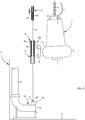
- the submersible machine 1 is lowered by means of the chain 9 and the runner is hanging in from the sliding bracket 15 by means of the upper cross bar 27, see figure 1 .
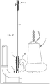
- the runner 14 engage the supporting member 12 and the submersible machine 1 is lowered further towards the supporting member 12, see figure 2 .
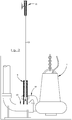
- the submersible machine 1 engage the supporting member 12, see figure 3 .
- the function of the inventive guide assembly during hoisting The submersible machine 1 is hoisted from the operative position and is displaced in relation to the runner 14, see figure 2 .
- the sliding bracket 15 engage the upper cross bar 27 of the runner 14 and brings the runner 14 upwards, see figure 1 .
- the runner 14 is secured, and thereafter the sliding bracket 15 may be removed/disengaged from the runner 14.
Landscapes
- Engineering & Computer Science (AREA)
- Mechanical Engineering (AREA)
- General Engineering & Computer Science (AREA)
- Chemical & Material Sciences (AREA)
- Chemical Kinetics & Catalysis (AREA)
- Structures Of Non-Positive Displacement Pumps (AREA)
Abstract
Description
- The present invention relates generally to the field of devices/assemblies for guiding submersible machines into tanks/receptacles, from the top of the tank towards an operative position of the submersible machine in the tank. The tank/receptacle is configured to house liquid, such as wastewater. The present invention relates specifically to the field of guide assemblies for submersible pumps. A submersible machine is designed and configured to be able to operate in a submerged configuration/position, i.e. be located entirely under the liquid surface in the tank. Thus, in the most preferred embodiment the present invention relates to a guide assembly suitable for use in a wastewater treatment plant.
- An inventive guide assembly intended for submersible machines comprises a top mount, a supporting member, two guide wires, a runner and a sliding bracket.
- The top mount is configured to be arranged at the upper region of the tank, i.e. at the top of the tank, and the supporting member is configured to be arranged in the tank, e.g. at the bottom of the tank. The two guide wires are running along each other in the vertical direction of the tank, wherein each of said guide wires is connected to the top mount at a first end, i.e. upper end, and is connected to a seat of the supporting member at a second end, i.e. lower end. The runner is configured to be displaceable along said guide wires, between the top mount and the supporting member. The runner comprises two guide members that engage the guide wires and that are connected to each other at the lower ends thereof, wherein the lower end of each guide member is configured to engage a corresponding seat of the supporting member when the runner is in the operative position. The sliding bracket is configured to be connected to the submersible machine and configured to engage the runner.
- The far most common way to land/position a submersible machine in the correct operative position in the tank is to use a guide rail assembly, see for instance applicants own
WO2015/170222 . A guide rail assembly comprises long guide rails, i.e. metal pipes having for instance squared or circular cross section. Said guide rails are connected to the wall of the tank at several locations by means of guide rail holders/brackets. In deep tanks, e.g. about 8-12 meters, each guide rail must be constituted by a number of guide rail segments connected in series, wherein each guide rail segment is constituted by (or cut from) a standard pipe having a length of forinstance 3 or 6 meters. Each guide rail segment and guide rail holder is expensive to manufacture, handle and to ship to the location of the tank/receptacle. Usually the guide rails are bought locally in order to minimize transportation costs, however this also leads to that the quality of the guide rail and cooperation with the guide rail holders/brackets can not be predicted/ foreseen before installation. - In applications intended for submersible pumps, the pump is usually guided/lowered towards and engages a discharge connection located at the bottom of the tank. It is crucial to obtain a correct landing of the pump in relation to the discharge connection in order to avoid leakage during operation of the pump, and when the pump is in the operative position the guide rails are usually not in contact with the sliding bracket of the pump. Thereto, if the submersible machine is not correctly landed/positioned it might lead to generation of vibrations during operation of the submersible machine.
- Document
US 5338116 disclose a guide assembly for a submersible mixer, in accordance with the preamble ofclaim 1. According to said document the mixer unit is connected to a frame that is lowered into a guide slide, wherein the guide slide is detachably connected to the frame. Thereafter, the mixer, frame and guide slide are jointly lowered into the receptacle all the way to the landing/operative position. - The present invention aims at obviating the aforementioned disadvantages and failings of previously known submersible machine guide assembly, and at providing an improved submersible machine guide assembly. A primary object of the present invention is to provide an improved submersible machine guide assembly of the initially defined type which guarantees proper landing/positioning of the submersible machine in the operative position.
- It is another object of the present invention to provide a submersible machine guide assembly, which is compact to ship and easy to handle, and thereby the entire submersible machine guide assembly may be packed and shipped to the location of the tank/receptacle without the need to buy local guide rails. It is another object of the present invention to provide a submersible machine guide assembly which is configured to match tanks/receptacles of different heights. It is yet another object of the present invention to provide a submersible machine guide assembly that requires less amount of metal and fewer components, such as guide rail segments and guide rail holders/brackets, and thereby generate minimal environmental footprint.
- According to the invention at least the primary object is attained by means of the initially defined submersible machine guide assembly having the features defined in the independent claim. Preferred embodiments of the present invention are further defined in the dependent claims.
- According to the present invention, there is provided a submersible machine guide assembly of the initially defined type, which is characterized in that the guide members of the runner are connected to each other at the upper ends thereof, and in that the sliding bracket is displaceable along the guide members of the runner when the runner is located in the operative position.
- Thus, the present invention is based on the insight of letting the runner land properly and be located in its operative position before the sliding bracket, i.e. the submersible machine, is properly landed and reaches its operative position. Thereby, the sliding bracket, i.e. the submersible machine, experience no technical difference between cooperation with the runner of the inventive submersible machine guide assembly and cooperation with a prior art guide rail solution extending all the way from the top of the tank to the operative position, in connection with the landing/positioning of the submersible machine.
- According to a preferred embodiment of the present invention, the two guide members of the runner are stationary connected to each other at the lower ends thereof and releasably connected to each other at the upper ends thereof. This means that the guide members are rigidly connected to each other at the same time as the sliding bracket in a controlled way may be removed/disengaged from the runner.
- According to a preferred embodiment, at least one guide member comprises internal engagement means. Said internal engagement means is configured to keep the corresponding guide wire free from large solid matter which otherwise might have negative effect on the function of the guide assembly. According to a more preferred embodiment, external engagement means are provided at the upper end of the corresponding guide wire, wherein the external engagement means are configured to engage the internal engagement means when the runner is located in the upper position. Thereby the runner will be automatically secured at the upper position when the sliding bracket, i.e. the submersible machine, has been hoisted to the upper position.
- According to a preferred embodiment, a spring assembly is arranged between the upper end of each guide wire and the top mount. Thereby proper guide wire tensioning is obtained at the same time as the risk of guide wire breakage during hoisting/lowering is reduced/avoided.
- According to a preferred embodiment, the runner has a vertical length that is equal to or more than 0,5 meters and equal to or less than 1,2 meters. Thereby, proper landing of the runner before landing of the sliding bracket, i.e. the submersible machine, is guaranteed at the same time as the guide assembly can be easily handled/shipped.
- Further advantages with and features of the invention will be apparent from the other dependent claims as well as from the following detailed description of preferred embodiments.
- A more complete understanding of the abovementioned and other features and advantages of the present invention will be apparent from the following detailed description of preferred embodiments in conjunction with the appended drawings, wherein:
- Fig. 1
- is a schematic side view of an inventive submersible machine guide assembly together with a submersible pump and a discharge connection, wherein the runner of the guide assembly and the pump are lowered towards the discharge connection (operative position),
- Fig. 2
- is a schematic side view of the submersible machine guide assembly according to
figure 1 , wherein the runner of the guide assembly is in the operative position and the pump is displaced in relation to the runner and lowered towards the discharge connection (operative position), - Fig. 3
- is a schematic side view of the submersible machine guide assembly according to
figures 1 and2 , wherein the runner of the guide assembly and the pump are located in the respective operative position, - Fig. 4
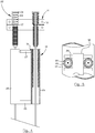
- is a schematic front view of a part of the inventive submersible machine guide assembly, partially cross sectioned, and
- Fig. 5
- is a schematic view from above of the runner and a section of the sliding bracket.
- The present invention relates to a submersible machine guide assembly, i.e. a guide assembly configured for guiding a
submersible machine 1 into a tank/receptacle 2, wherein saidtank 2 is configured to house liquid, especially wastewater. Thus, the inventive guide assembly is in the preferred embodiment configured for use in a wastewater treatment plant such as a wastewater pump station, a racetrack, a digester, etc. - A
submersible machine 1 is designed and configured to be able to operate in a submerged configuration/position, i.e. during operation be located entirely under the liquid surface in thetank 2. Thus, an operative position of thesubmersible machine 1 is located inside thetank 2 and the guide assembly is configured to guide the submersible machine from the top of thetank 2 towards said operative position. The operative position of the submersible machine is in the preferred embodiment located at thebottom 3 of thetank 2. The axial depth of thetank 2 is usually in the range up to 12-15 meters, and usually at least 6 meters. - It shall be realized that a
submersible machine 1 during operation must not be entirely located under the liquid surface but may continuously or occasionally be partly located above the liquid surface in thetank 2. Submersible machines as referred to herein, comprises an electrical motor arranged in a liquid tight housing, preferably made of metal, and a drive shaft extending from the electrical motor. An impeller/propeller is connected to the drive shaft and is driven in rotation by said drive shaft and electrical motor during operation of thesubmersible machine 1. The electrical motor is powered via anelectrical cable 4 extending from the top of thetank 2, and thesubmersible machine 1 comprises a liquid tight lead-through 5 receiving saidelectrical cable 4. Thesubmersible machine 1 may also comprise a control unit, such as an intelligent drive or VFD, located inside the liquid tight housing. The components of the submersible machine are usually cold down by means of the liquid surrounding the submersible machine. - The
submersible machine 1 is in the preferred embodiment constituted by a submersible pump, especially a wastewater pump. However, it shall be realized that also other submersible machines are conceivable such as a submersible mixer, especially a wastewater mixer. Hereinafter the present invention will be described in detail in connection with a pump station and a submersible pump, however not limited thereto. Reference is made to all figures. - The
submersible pump 1 comprises an impeller located in a volute 6, wherein the impeller during operation of thepump 1 is configured to draw liquid into said volute 6 through aninlet 7 and discharge liquid from said volute 6 though anoutlet 8. Thepump 1 is hoisted and lowered by means of a chain/wire 9 connected to ahandle 10 arranged at the top of thepump 1. The chain/wire 9 may be disconnected from thepump 1 when thepump 1 is in the operative position in thetank 2. - The inventive submersible machine guide assembly comprises a
top mount 11, a supportingmember 12, twoguide wires 13, arunner 14 and a slidingbracket 15. - The
top mount 11 is configured to be arranged at the upper region of thetank 2. i.e. accessible by an operator preferably from an upper opening of thetank 2. In a pump station application (or the like applications) the upper opening is closed by a manhole cover or the like during operation, and thetop mount 11 is located inside thetank 2. In a racetrack application (or the like applications) thetank 2 is upon upwards and the top mount may be located above the upper rim of thetank 2. Thetop mount 11 is configured to be rigidly attached to a stationary structure, such as the inside of the tank wall or underside of the tank roof, by means of bolts or the like. It shall be pointed out that thetop mount 11 may comprises two separate elements but still considered as a single top mount arrangement. - In the most elementary embodiment, the
top mount 11 is constituted by two eyebolts connected to thetank 2. In the preferred and disclosed embodiment thetop mount 11 comprises anattachment plate 16 and two angled-shapedcantilevers 17 connected to and projecting from theattachment plate 16, wherein the free ends of thecantilevers 17 are heading each other. - The supporting
member 12 is configured to be arranged in thetank 2, preferably at the lower region of thetank 2. The supportingmember 12 is configured to be rigidly attached to a stationary structure, such as thetank bottom 3, by means of bolts or the like. The supportingmember 12 is configured to receive thesubmersible machine 1, when the submersible machine is in the operative position. In a pump station application the supportingmember 12 is constituted by a discharge connection. In a mixer application the supportingmember 12 is constituted by a seat/stand. The discloseddischarge connection 12 comprises aninlet 18, wherein theoutlet 8 of thepump 1 is configured to engage saidinlet 18 of thedischarge connection 12 when thepump 1 is in the operative position. Thedischarge connection 12 is connected to anoutlet pipe 19 in a conventional way. - Said two
guide wires 13 are configured to run along each other in the vertical direction of thetank 2. Eachguide wire 13 is connected to thetop mount 11 at a first/upper end of theguide wire 13 and connected to aseat 20 of the supportingmember 12 at a second/lower end of theguide wire 13. Theguide wires 13 are preferably made of twisted steel wire. In the disclosed embodiment theseat 20 of thedischarge connection 12 is constituted by an upright projection, preferably in the shape of a truncated cone. Theguide wire 13 is connected to the top of the upright projection, preferably by means of aneyebolt 21 of less radial extension than the upright projection. - Preferably each
guide wire 13 is provided with a tensioning assembly, and in the preferred embodiment the tensioning assembly is constituted by aspring assembly 22 arranged between the first/upper end of theguide wire 13 and thetop mount 11. In the disclosed embodiment, thespring assembly 22 comprises acompression spring 23 arranged on the upper side of thecantilever 17 of thetop mount 11, wherein the first/upper end of theguide wire 13 is connected to the upper end of thecompression spring 23, e.g. by means of awasher 24 or the like. Preferably thecompression spring 23 is arranged about theguide wire 13. During installation of the guide assembly the lower end of theguide wire 13 is connected to the supportingmember 12 and when theguide wire 13 has the correct length the upper end of theguide wire 13 is connected to the upper end of thebiased compression spring 23. Thus, theguide wires 13 may have a raw length exceeding the specific installation depth. - The runner/
slide 14 is configured to be displaced along saidguide wires 13, between thetop mount 11 and the supportingmember 12. Therunner 14 comprises twoguide members 25, wherein eachguide member 25 engage oneguide wire 13 each. The lower end of eachguide member 25 is configured to engage thecorresponding seat 20 of the supportingmember 12 when therunner 14 is in its operative position. The twoguide members 25 are extending along each other and are preferably arranged in parallel to each other. Theguide members 25 are rigidly connected to each other at the lower ends thereof, by means of alower cross bar 26. Thereto, theguide members 25 are connected to each other at the upper ends thereof, by means of anupper cross bar 27. Preferably theguide members 25 are releasable connected to each other at the upper ends thereof. - In the preferred embodiment the
guide members 25 are constituted by guide pipes, wherein theguide pipes 25 are arranged about theguide wires 13. In an alternative embodiment theguide members 25 are constituted by elements having approximately U-shaped cross section, wherein the U-shaped elements are open away from each other and theguide wires 13 are arranged surrounded by the U-shaped elements. According to an alternative embodiment eachguide member 25 is constituted by a guide pipe having an axially extending slot configured to receive theguide wire 13. Radiallyopen guide members 25 entail that therunner 14 may be installed after theguide wires 13 are installed. Preferably, therunner 14, i.e. theguide members 25, has a vertical length that is equal to or more than 0,5 meters and equal to or less than 1,2 meters, preferably in the range 0,8-1 meters. - The sliding
bracket 15 is configured to be connected to thesubmersible machine 1 and configured to engage therunner 14. In the preferred embodiment the slidingbracket 15 is rigidly and stationary connected to thesubmersible machine 1. The slidingbracket 15 comprises anabutment surface 28 configured to abut/engage acorresponding abutment surface 29 of the supportingmember 12, when the submersible machine is in its operative position. In the disclosed embodiment thepump 1 will hang from thedischarge connection 12 by means of the slidingbracket 15 such that theoutlet 8 of thepump 1 rest against theinlet 18 of thedischarge connection 12 due to the weight of thepump 1. - The sliding
bracket 15 comprises aguide member fork 30, saidguide member fork 30 being configured to cooperate with theguide members 25 of therunner 14, such that the slidingbracket 15 is displaceable along theguide members 25 of therunner 14, i.e. in the vertical direction, at least when therunner 14 is located in its operative position. Theguide member fork 30 is configured to have little or no play in the radial direction in relation to theguide members 25 of therunner 14, such that thesubmersible machine 1 can be properly landed/positioned at the operative position after therunner 14 has reached its operative position. - In the embodiment wherein the
guide members 25 of therunner 14 are releasable connected to each other at the upper ends thereof, the slidingbracket 15 may be removed from the engagement with therunner 14 when therunner 14 is located at thetop mount 11. In the disclosed embodiment theupper cross bar 27 is pivotably connected to one of theguide members 25. Theupper cross bar 27 is biased into a position wherein theupper cross bar 27 bridge over the distance between theguide members 25 and is abutting aseat 31 of theother guide member 25. Thus, theupper cross bar 27 may be located in a first position allowing the slidingbracket 15 to engage and disengage therunner 14, and be located in a second position securing the engagement between the slidingbracket 15 and therunner 14. Preferably theupper cross bar 27 is arranged to pivot in an axially extending plane. - According to the disclosed embodiment at least one
guide member 13, preferably both guide wires, comprises internal engagement means 32. Said internal engagement means 32 is preferably made of bristles connected to the inner surface of theguide member 25. The internal engagement means 32 are configured to remove solid matter from theguide wires 13. Thereto, it is preferred that external engagement means 33 are provided at the upper end of thecorresponding guide wire 13. Said external engagement means 33 is preferably made of bristles connected to the outer surface of apipe segment 34 that is connected to thecantilever 17 of thetop mount 11. Thus, the external engagement means 32 is configured to engage the internal engagement means 33 when therunner 14 is located in the upper position, like "Velcro". - The function of the inventive guide assembly during lowering. The
runner 14 is kept at the upper position adjacent thetop mount 11. The slidingbracket 15 engages therunner 14 and therunner 14 is released from its upper position adjacent thetop mount 11. Thesubmersible machine 1 is lowered by means of the chain 9 and the runner is hanging in from the slidingbracket 15 by means of theupper cross bar 27, seefigure 1 . Thereafter therunner 14 engage the supportingmember 12 and thesubmersible machine 1 is lowered further towards the supportingmember 12, seefigure 2 . Thereafter thesubmersible machine 1 engage the supportingmember 12, seefigure 3 . - The function of the inventive guide assembly during hoisting. The
submersible machine 1 is hoisted from the operative position and is displaced in relation to therunner 14, seefigure 2 . The slidingbracket 15 engage theupper cross bar 27 of therunner 14 and brings therunner 14 upwards, seefigure 1 . When therunner 14 reaches its upper position, therunner 14 is secured, and thereafter the slidingbracket 15 may be removed/disengaged from therunner 14. - The invention is not limited only to the embodiments described above and shown in the drawings, which primarily have an illustrative and exemplifying purpose. This patent application is intended to cover all adjustments and variants of the preferred embodiments described herein, thus the present invention is defined by the wording of the appended claims and thus the equipment may be modified in all kinds of ways within the scope of the appended claims.
- It shall also be pointed out that all information about/concerning terms such as above, under, upper, lower, etc., shall be interpreted/read having the equipment oriented according to the figures, having the drawings oriented such that the references can be properly read. Thus, such terms only indicates mutual relations in the shown embodiments, which relations may be changed if the inventive equipment is provided with another structure/design.
- It shall also be pointed out that even thus it is not explicitly stated that features from a specific embodiment may be combined with features from another embodiment, the combination shall be considered obvious, if the combination is possible.
Claims (8)
- A submersible machine guide assembly suitable for guiding a submersible machine (1) from an upper position towards an operative position, the guide assembly comprising:- a top mount (11) configured to be arranged at the upper region of the tank (2),- a supporting member (12) configured to be arranged in the tank (2),- two guide wires (13) running along each other in the vertical direction of the tank (2), wherein each of said guide wires (13) is connected to the top mount (11) at a first end and is connected to a seat (20) of the supporting member (12) at a second end,- a runner (14) that is displaceable along said guide wires (13), the runner (14) comprising two guide members (25) that engage the guide wires (13) and that are connected to each other at the lower ends thereof, wherein the lower end of each guide member (25) is configured to engage the corresponding seat (20) of the supporting member (12) when the runner (14) is in the operative position, and- a sliding bracket (15) configured to be connected to the submersible machine (1) and configured to engage the runner (14),characterized in that the guide members (25) are connected to each other at the upper ends thereof, and in that the sliding bracket (15) is displaceable along the guide members (25) of the runner (14) when the runner (14) is located in the operative position.
- The submersible machine guide assembly according to claim 1, wherein the guide assembly is constituted by a submersible pump guide assembly, and wherein the supporting member (12) is constituted by a discharge connection.
- The submersible machine guide assembly according to claim 1 or 2, wherein the two guide members (25) of the runner (14) are stationary connected to each other at the lower ends thereof and releasably connected to each other at the upper ends thereof.
- The submersible machine guide assembly according to any of claims 1-3, wherein at least one guide member (25) comprises internal engagement means (32).
- The submersible machine guide assembly according to claim 4, wherein external engagement means (33) are provided at the upper end of the corresponding guide wire (13), wherein the external engagement means (33) are configured to engage the internal engagement means (32) when the runner (14) is located in the upper position.
- The submersible machine guide assembly according to any preceding claim, wherein a spring assembly (22) is arranged between the first end of each guide wire (13) and the top mount (11).
- The submersible machine guide assembly according to any preceding claim, wherein the runner (14) has a vertical length that is equal to or more than 0,5 meters and equal to or less than 1,2 meters.
- The submersible machine guide assembly according to any preceding claim, wherein each seat (20) is constituted by an upright projection.
Priority Applications (8)
| Application Number | Priority Date | Filing Date | Title |
|---|---|---|---|
| EP17150689.2A EP3346139B1 (en) | 2017-01-09 | 2017-01-09 | A submersible machine guide assembly |
| PL17150689T PL3346139T3 (en) | 2017-01-09 | 2017-01-09 | A submersible machine guide assembly |
| ES17150689T ES2774483T3 (en) | 2017-01-09 | 2017-01-09 | Guide assembly of a submersible machine |
| HUE17150689A HUE047938T2 (en) | 2017-01-09 | 2017-01-09 | A submersible machine guide assembly |
| DK17150689.2T DK3346139T3 (en) | 2017-01-09 | 2017-01-09 | Submersible machine driver device |
| US16/476,346 US10982689B2 (en) | 2017-01-09 | 2018-01-08 | Submersible machine guide assembly |
| PCT/EP2018/050311 WO2018127579A1 (en) | 2017-01-09 | 2018-01-08 | A submersible machine guide assembly |
| CN201880006136.XA CN110168232B (en) | 2017-01-09 | 2018-01-08 | Underwater machine guidance assembly |
Applications Claiming Priority (1)
| Application Number | Priority Date | Filing Date | Title |
|---|---|---|---|
| EP17150689.2A EP3346139B1 (en) | 2017-01-09 | 2017-01-09 | A submersible machine guide assembly |
Publications (2)
| Publication Number | Publication Date |
|---|---|
| EP3346139A1 true EP3346139A1 (en) | 2018-07-11 |
| EP3346139B1 EP3346139B1 (en) | 2019-11-27 |
Family
ID=57794133
Family Applications (1)
| Application Number | Title | Priority Date | Filing Date |
|---|---|---|---|
| EP17150689.2A Not-in-force EP3346139B1 (en) | 2017-01-09 | 2017-01-09 | A submersible machine guide assembly |
Country Status (8)
| Country | Link |
|---|---|
| US (1) | US10982689B2 (en) |
| EP (1) | EP3346139B1 (en) |
| CN (1) | CN110168232B (en) |
| DK (1) | DK3346139T3 (en) |
| ES (1) | ES2774483T3 (en) |
| HU (1) | HUE047938T2 (en) |
| PL (1) | PL3346139T3 (en) |
| WO (1) | WO2018127579A1 (en) |
Families Citing this family (3)
| Publication number | Priority date | Publication date | Assignee | Title |
|---|---|---|---|---|
| EP3346139B1 (en) * | 2017-01-09 | 2019-11-27 | Xylem Europe GmbH | A submersible machine guide assembly |
| CN113979533B (en) * | 2021-11-24 | 2025-02-18 | 甘肃大禹节水集团水利水电工程有限责任公司 | A submersible propulsion assembly for rural sewage treatment system |
| CN117212190B (en) * | 2023-09-22 | 2026-05-15 | 中信环境水务(无极县)有限公司 | A method for fixing and installing a non-coupling device for a submersible electric pump |
Citations (4)
| Publication number | Priority date | Publication date | Assignee | Title |
|---|---|---|---|---|
| US3313347A (en) * | 1963-01-09 | 1967-04-11 | Gray Tool Co | Well completion procedures and apparatus |
| US3603385A (en) * | 1969-02-04 | 1971-09-07 | Offshore Systems Inc | Method and apparatus for removably coupling a blowout preventer stack to an underwater wellhead casing |
| US5338116A (en) | 1991-07-17 | 1994-08-16 | E+M Maschinenbau Gmbh | Guide means for a submersible mixer and the like |
| WO2015170222A1 (en) | 2014-05-07 | 2015-11-12 | Xylem Ip Management S.À R.L. | Guide rail assembly as well as guide rail holder |
Family Cites Families (9)
| Publication number | Priority date | Publication date | Assignee | Title |
|---|---|---|---|---|
| US3427982A (en) * | 1967-09-25 | 1969-02-18 | Flygt Corp | Submersible pumps |
| DE1816852A1 (en) * | 1968-12-24 | 1970-06-25 | Albert Blum | Pump unit that can be lowered into a container |
| DE1912963C2 (en) * | 1969-03-14 | 1970-07-30 | Klein Schanzlin & Becker Ag | Guide device for in a container or the like. Lowerable submersible pump unit |
| US3771915A (en) * | 1971-11-10 | 1973-11-13 | Peabody Barnes | Submersible pump remotely controlled detachable fitting |
| DE2448940A1 (en) * | 1974-10-15 | 1976-04-29 | Klein Schanzlin & Becker Ag | SUBMERSIBLE PUMP |
| US4324531A (en) * | 1978-06-12 | 1982-04-13 | Oy E. Sarlin Ab | Guide apparatus for a submersible pump |
| DE19528701A1 (en) * | 1995-08-04 | 1997-02-06 | Wilo Gmbh | Rope guide for submersible pumps |
| CN103057679B (en) * | 2013-01-11 | 2015-05-20 | 哈尔滨工程大学 | Mutual butt joint device for double intelligent underwater robots and butt joint method |
| EP3346139B1 (en) * | 2017-01-09 | 2019-11-27 | Xylem Europe GmbH | A submersible machine guide assembly |
-
2017
- 2017-01-09 EP EP17150689.2A patent/EP3346139B1/en not_active Not-in-force
- 2017-01-09 PL PL17150689T patent/PL3346139T3/en unknown
- 2017-01-09 DK DK17150689.2T patent/DK3346139T3/en active
- 2017-01-09 HU HUE17150689A patent/HUE047938T2/en unknown
- 2017-01-09 ES ES17150689T patent/ES2774483T3/en active Active
-
2018
- 2018-01-08 US US16/476,346 patent/US10982689B2/en not_active Expired - Fee Related
- 2018-01-08 WO PCT/EP2018/050311 patent/WO2018127579A1/en not_active Ceased
- 2018-01-08 CN CN201880006136.XA patent/CN110168232B/en not_active Expired - Fee Related
Patent Citations (4)
| Publication number | Priority date | Publication date | Assignee | Title |
|---|---|---|---|---|
| US3313347A (en) * | 1963-01-09 | 1967-04-11 | Gray Tool Co | Well completion procedures and apparatus |
| US3603385A (en) * | 1969-02-04 | 1971-09-07 | Offshore Systems Inc | Method and apparatus for removably coupling a blowout preventer stack to an underwater wellhead casing |
| US5338116A (en) | 1991-07-17 | 1994-08-16 | E+M Maschinenbau Gmbh | Guide means for a submersible mixer and the like |
| WO2015170222A1 (en) | 2014-05-07 | 2015-11-12 | Xylem Ip Management S.À R.L. | Guide rail assembly as well as guide rail holder |
Also Published As
| Publication number | Publication date |
|---|---|
| PL3346139T3 (en) | 2020-06-01 |
| ES2774483T3 (en) | 2020-07-21 |
| EP3346139B1 (en) | 2019-11-27 |
| US20200040913A1 (en) | 2020-02-06 |
| DK3346139T3 (en) | 2020-02-24 |
| WO2018127579A1 (en) | 2018-07-12 |
| US10982689B2 (en) | 2021-04-20 |
| CN110168232B (en) | 2021-04-09 |
| HUE047938T2 (en) | 2020-05-28 |
| CN110168232A (en) | 2019-08-23 |
Similar Documents
| Publication | Publication Date | Title |
|---|---|---|
| US10982689B2 (en) | Submersible machine guide assembly | |
| EP0611269B1 (en) | Sewage pump station | |
| US7534098B2 (en) | Suction distribution and disconnection system for a submersible pump | |
| AU2010294017A1 (en) | Easy maintenance hydraulic turbine engine | |
| US10392237B2 (en) | Chain tensioning arrangement as well as pump station | |
| CA2898044A1 (en) | Pump station | |
| JP5787787B2 (en) | Hydroelectric generator | |
| JP2016135968A (en) | Attaching/detaching device and drainage system | |
| EP0197903B1 (en) | Mixing apparatus | |
| US6386487B1 (en) | Stretching device for electric cables | |
| EP0080982B1 (en) | A device for guiding a submersible pump unit | |
| US20030138326A1 (en) | Submersible pump system | |
| JPH0810798A (en) | Digestion tank agitator | |
| CA1106697A (en) | Submersible pump arrangement | |
| JP2011106331A (en) | Column type submerged pump | |
| JP4261971B2 (en) | Vertical water agitator in water treatment tank and its draft tube mounting structure | |
| CN110271952A (en) | A kind of Alcula type shipment divergence type submersible water impeller | |
| JP5327718B2 (en) | Column type submersible pump | |
| US5338116A (en) | Guide means for a submersible mixer and the like | |
| JP4116189B2 (en) | Submersible pump equipment | |
| NZ198423A (en) | Submersible pump: pump casing formed as curved tube with integral motor casing | |
| JP5188130B2 (en) | Submersible pump device | |
| NO117977B (en) | ||
| KR102857522B1 (en) | Vertical multi-stage submersible pump with low water suction structure and enhanced motor cooling performance | |
| CN117869378B (en) | Submersible sewage pump quick installation structure and installation method thereof |
Legal Events
| Date | Code | Title | Description |
|---|---|---|---|
| PUAI | Public reference made under article 153(3) epc to a published international application that has entered the european phase |
Free format text: ORIGINAL CODE: 0009012 |
|
| STAA | Information on the status of an ep patent application or granted ep patent |
Free format text: STATUS: THE APPLICATION HAS BEEN PUBLISHED |
|
| AK | Designated contracting states |
Kind code of ref document: A1 Designated state(s): AL AT BE BG CH CY CZ DE DK EE ES FI FR GB GR HR HU IE IS IT LI LT LU LV MC MK MT NL NO PL PT RO RS SE SI SK SM TR |
|
| AX | Request for extension of the european patent |
Extension state: BA ME |
|
| STAA | Information on the status of an ep patent application or granted ep patent |
Free format text: STATUS: REQUEST FOR EXAMINATION WAS MADE |
|
| 17P | Request for examination filed |
Effective date: 20190107 |
|
| RBV | Designated contracting states (corrected) |
Designated state(s): AL AT BE BG CH CY CZ DE DK EE ES FI FR GB GR HR HU IE IS IT LI LT LU LV MC MK MT NL NO PL PT RO RS SE SI SK SM TR |
|
| RIC1 | Information provided on ipc code assigned before grant |
Ipc: E21B 41/10 20060101ALI20190513BHEP Ipc: F04D 29/60 20060101AFI20190513BHEP Ipc: B01F 7/00 20060101ALI20190513BHEP |
|
| GRAP | Despatch of communication of intention to grant a patent |
Free format text: ORIGINAL CODE: EPIDOSNIGR1 |
|
| STAA | Information on the status of an ep patent application or granted ep patent |
Free format text: STATUS: GRANT OF PATENT IS INTENDED |
|
| RAP1 | Party data changed (applicant data changed or rights of an application transferred) |
Owner name: XYLEM EUROPE GMBH |
|
| INTG | Intention to grant announced |
Effective date: 20190709 |
|
| GRAS | Grant fee paid |
Free format text: ORIGINAL CODE: EPIDOSNIGR3 |
|
| GRAA | (expected) grant |
Free format text: ORIGINAL CODE: 0009210 |
|
| STAA | Information on the status of an ep patent application or granted ep patent |
Free format text: STATUS: THE PATENT HAS BEEN GRANTED |
|
| AK | Designated contracting states |
Kind code of ref document: B1 Designated state(s): AL AT BE BG CH CY CZ DE DK EE ES FI FR GB GR HR HU IE IS IT LI LT LU LV MC MK MT NL NO PL PT RO RS SE SI SK SM TR |
|
| REG | Reference to a national code |
Ref country code: GB Ref legal event code: FG4D |
|
| REG | Reference to a national code |
Ref country code: CH Ref legal event code: EP |
|
| REG | Reference to a national code |
Ref country code: AT Ref legal event code: REF Ref document number: 1206973 Country of ref document: AT Kind code of ref document: T Effective date: 20191215 |
|
| REG | Reference to a national code |
Ref country code: DE Ref legal event code: R096 Ref document number: 602017008979 Country of ref document: DE |
|
| REG | Reference to a national code |
Ref country code: IE Ref legal event code: FG4D |
|
| REG | Reference to a national code |
Ref country code: NO Ref legal event code: T2 Effective date: 20191127 |
|
| REG | Reference to a national code |
Ref country code: SE Ref legal event code: TRGR |
|
| REG | Reference to a national code |
Ref country code: FI Ref legal event code: FGE |
|
| REG | Reference to a national code |
Ref country code: DK Ref legal event code: T3 Effective date: 20200217 |
|
| REG | Reference to a national code |
Ref country code: NL Ref legal event code: FP |
|
| REG | Reference to a national code |
Ref country code: LT Ref legal event code: MG4D |
|
| PG25 | Lapsed in a contracting state [announced via postgrant information from national office to epo] |
Ref country code: GR Free format text: LAPSE BECAUSE OF FAILURE TO SUBMIT A TRANSLATION OF THE DESCRIPTION OR TO PAY THE FEE WITHIN THE PRESCRIBED TIME-LIMIT Effective date: 20200228 Ref country code: BG Free format text: LAPSE BECAUSE OF FAILURE TO SUBMIT A TRANSLATION OF THE DESCRIPTION OR TO PAY THE FEE WITHIN THE PRESCRIBED TIME-LIMIT Effective date: 20200227 Ref country code: LT Free format text: LAPSE BECAUSE OF FAILURE TO SUBMIT A TRANSLATION OF THE DESCRIPTION OR TO PAY THE FEE WITHIN THE PRESCRIBED TIME-LIMIT Effective date: 20191127 Ref country code: LV Free format text: LAPSE BECAUSE OF FAILURE TO SUBMIT A TRANSLATION OF THE DESCRIPTION OR TO PAY THE FEE WITHIN THE PRESCRIBED TIME-LIMIT Effective date: 20191127 |
|
| REG | Reference to a national code |
Ref country code: HU Ref legal event code: AG4A Ref document number: E047938 Country of ref document: HU |
|
| PG25 | Lapsed in a contracting state [announced via postgrant information from national office to epo] |
Ref country code: IS Free format text: LAPSE BECAUSE OF FAILURE TO SUBMIT A TRANSLATION OF THE DESCRIPTION OR TO PAY THE FEE WITHIN THE PRESCRIBED TIME-LIMIT Effective date: 20200327 Ref country code: HR Free format text: LAPSE BECAUSE OF FAILURE TO SUBMIT A TRANSLATION OF THE DESCRIPTION OR TO PAY THE FEE WITHIN THE PRESCRIBED TIME-LIMIT Effective date: 20191127 Ref country code: RS Free format text: LAPSE BECAUSE OF FAILURE TO SUBMIT A TRANSLATION OF THE DESCRIPTION OR TO PAY THE FEE WITHIN THE PRESCRIBED TIME-LIMIT Effective date: 20191127 |
|
| PG25 | Lapsed in a contracting state [announced via postgrant information from national office to epo] |
Ref country code: AL Free format text: LAPSE BECAUSE OF FAILURE TO SUBMIT A TRANSLATION OF THE DESCRIPTION OR TO PAY THE FEE WITHIN THE PRESCRIBED TIME-LIMIT Effective date: 20191127 |
|
| REG | Reference to a national code |
Ref country code: ES Ref legal event code: FG2A Ref document number: 2774483 Country of ref document: ES Kind code of ref document: T3 Effective date: 20200721 |
|
| PG25 | Lapsed in a contracting state [announced via postgrant information from national office to epo] |
Ref country code: CZ Free format text: LAPSE BECAUSE OF FAILURE TO SUBMIT A TRANSLATION OF THE DESCRIPTION OR TO PAY THE FEE WITHIN THE PRESCRIBED TIME-LIMIT Effective date: 20191127 Ref country code: RO Free format text: LAPSE BECAUSE OF FAILURE TO SUBMIT A TRANSLATION OF THE DESCRIPTION OR TO PAY THE FEE WITHIN THE PRESCRIBED TIME-LIMIT Effective date: 20191127 Ref country code: PT Free format text: LAPSE BECAUSE OF FAILURE TO SUBMIT A TRANSLATION OF THE DESCRIPTION OR TO PAY THE FEE WITHIN THE PRESCRIBED TIME-LIMIT Effective date: 20200419 Ref country code: EE Free format text: LAPSE BECAUSE OF FAILURE TO SUBMIT A TRANSLATION OF THE DESCRIPTION OR TO PAY THE FEE WITHIN THE PRESCRIBED TIME-LIMIT Effective date: 20191127 |
|
| REG | Reference to a national code |
Ref country code: DE Ref legal event code: R097 Ref document number: 602017008979 Country of ref document: DE |
|
| PG25 | Lapsed in a contracting state [announced via postgrant information from national office to epo] |
Ref country code: SM Free format text: LAPSE BECAUSE OF FAILURE TO SUBMIT A TRANSLATION OF THE DESCRIPTION OR TO PAY THE FEE WITHIN THE PRESCRIBED TIME-LIMIT Effective date: 20191127 Ref country code: MC Free format text: LAPSE BECAUSE OF FAILURE TO SUBMIT A TRANSLATION OF THE DESCRIPTION OR TO PAY THE FEE WITHIN THE PRESCRIBED TIME-LIMIT Effective date: 20191127 Ref country code: SK Free format text: LAPSE BECAUSE OF FAILURE TO SUBMIT A TRANSLATION OF THE DESCRIPTION OR TO PAY THE FEE WITHIN THE PRESCRIBED TIME-LIMIT Effective date: 20191127 |
|
| REG | Reference to a national code |
Ref country code: CH Ref legal event code: PL |
|
| REG | Reference to a national code |
Ref country code: AT Ref legal event code: MK05 Ref document number: 1206973 Country of ref document: AT Kind code of ref document: T Effective date: 20191127 |
|
| PLBE | No opposition filed within time limit |
Free format text: ORIGINAL CODE: 0009261 |
|
| STAA | Information on the status of an ep patent application or granted ep patent |
Free format text: STATUS: NO OPPOSITION FILED WITHIN TIME LIMIT |
|
| REG | Reference to a national code |
Ref country code: BE Ref legal event code: MM Effective date: 20200131 |
|
| PG25 | Lapsed in a contracting state [announced via postgrant information from national office to epo] |
Ref country code: LU Free format text: LAPSE BECAUSE OF NON-PAYMENT OF DUE FEES Effective date: 20200109 |
|
| 26N | No opposition filed |
Effective date: 20200828 |
|
| PG25 | Lapsed in a contracting state [announced via postgrant information from national office to epo] |
Ref country code: AT Free format text: LAPSE BECAUSE OF FAILURE TO SUBMIT A TRANSLATION OF THE DESCRIPTION OR TO PAY THE FEE WITHIN THE PRESCRIBED TIME-LIMIT Effective date: 20191127 Ref country code: BE Free format text: LAPSE BECAUSE OF NON-PAYMENT OF DUE FEES Effective date: 20200131 Ref country code: LI Free format text: LAPSE BECAUSE OF NON-PAYMENT OF DUE FEES Effective date: 20200131 Ref country code: SI Free format text: LAPSE BECAUSE OF FAILURE TO SUBMIT A TRANSLATION OF THE DESCRIPTION OR TO PAY THE FEE WITHIN THE PRESCRIBED TIME-LIMIT Effective date: 20191127 Ref country code: CH Free format text: LAPSE BECAUSE OF NON-PAYMENT OF DUE FEES Effective date: 20200131 |
|
| PG25 | Lapsed in a contracting state [announced via postgrant information from national office to epo] |
Ref country code: IE Free format text: LAPSE BECAUSE OF NON-PAYMENT OF DUE FEES Effective date: 20200109 |
|
| PGFP | Annual fee paid to national office [announced via postgrant information from national office to epo] |
Ref country code: PL Payment date: 20201218 Year of fee payment: 5 |
|
| PGFP | Annual fee paid to national office [announced via postgrant information from national office to epo] |
Ref country code: FI Payment date: 20210127 Year of fee payment: 5 Ref country code: NL Payment date: 20210126 Year of fee payment: 5 Ref country code: NO Payment date: 20210127 Year of fee payment: 5 |
|
| PGFP | Annual fee paid to national office [announced via postgrant information from national office to epo] |
Ref country code: ES Payment date: 20210201 Year of fee payment: 5 |
|
| PGFP | Annual fee paid to national office [announced via postgrant information from national office to epo] |
Ref country code: HU Payment date: 20220101 Year of fee payment: 6 Ref country code: GB Payment date: 20220127 Year of fee payment: 6 Ref country code: DK Payment date: 20220127 Year of fee payment: 6 Ref country code: DE Payment date: 20220127 Year of fee payment: 6 |
|
| PG25 | Lapsed in a contracting state [announced via postgrant information from national office to epo] |
Ref country code: TR Free format text: LAPSE BECAUSE OF FAILURE TO SUBMIT A TRANSLATION OF THE DESCRIPTION OR TO PAY THE FEE WITHIN THE PRESCRIBED TIME-LIMIT Effective date: 20191127 Ref country code: MT Free format text: LAPSE BECAUSE OF FAILURE TO SUBMIT A TRANSLATION OF THE DESCRIPTION OR TO PAY THE FEE WITHIN THE PRESCRIBED TIME-LIMIT Effective date: 20191127 Ref country code: CY Free format text: LAPSE BECAUSE OF FAILURE TO SUBMIT A TRANSLATION OF THE DESCRIPTION OR TO PAY THE FEE WITHIN THE PRESCRIBED TIME-LIMIT Effective date: 20191127 |
|
| PGFP | Annual fee paid to national office [announced via postgrant information from national office to epo] |
Ref country code: SE Payment date: 20220127 Year of fee payment: 6 Ref country code: IT Payment date: 20220119 Year of fee payment: 6 Ref country code: FR Payment date: 20220125 Year of fee payment: 6 |
|
| PG25 | Lapsed in a contracting state [announced via postgrant information from national office to epo] |
Ref country code: MK Free format text: LAPSE BECAUSE OF FAILURE TO SUBMIT A TRANSLATION OF THE DESCRIPTION OR TO PAY THE FEE WITHIN THE PRESCRIBED TIME-LIMIT Effective date: 20191127 |
|
| REG | Reference to a national code |
Ref country code: FI Ref legal event code: MAE |
|
| REG | Reference to a national code |
Ref country code: NO Ref legal event code: MMEP |
|
| REG | Reference to a national code |
Ref country code: NL Ref legal event code: MM Effective date: 20220201 |
|
| PG25 | Lapsed in a contracting state [announced via postgrant information from national office to epo] |
Ref country code: NO Free format text: LAPSE BECAUSE OF NON-PAYMENT OF DUE FEES Effective date: 20220131 Ref country code: NL Free format text: LAPSE BECAUSE OF NON-PAYMENT OF DUE FEES Effective date: 20220201 Ref country code: FI Free format text: LAPSE BECAUSE OF NON-PAYMENT OF DUE FEES Effective date: 20220109 |
|
| REG | Reference to a national code |
Ref country code: ES Ref legal event code: FD2A Effective date: 20230224 |
|
| PG25 | Lapsed in a contracting state [announced via postgrant information from national office to epo] |
Ref country code: ES Free format text: LAPSE BECAUSE OF NON-PAYMENT OF DUE FEES Effective date: 20220110 |
|
| PG25 | Lapsed in a contracting state [announced via postgrant information from national office to epo] |
Ref country code: PL Free format text: LAPSE BECAUSE OF NON-PAYMENT OF DUE FEES Effective date: 20220109 |
|
| REG | Reference to a national code |
Ref country code: DE Ref legal event code: R119 Ref document number: 602017008979 Country of ref document: DE |
|
| REG | Reference to a national code |
Ref country code: DK Ref legal event code: EBP Effective date: 20230131 |
|
| REG | Reference to a national code |
Ref country code: SE Ref legal event code: EUG |
|
| GBPC | Gb: european patent ceased through non-payment of renewal fee |
Effective date: 20230109 |
|
| PG25 | Lapsed in a contracting state [announced via postgrant information from national office to epo] |
Ref country code: SE Free format text: LAPSE BECAUSE OF NON-PAYMENT OF DUE FEES Effective date: 20230110 Ref country code: GB Free format text: LAPSE BECAUSE OF NON-PAYMENT OF DUE FEES Effective date: 20230109 Ref country code: DE Free format text: LAPSE BECAUSE OF NON-PAYMENT OF DUE FEES Effective date: 20230801 |
|
| PG25 | Lapsed in a contracting state [announced via postgrant information from national office to epo] |
Ref country code: HU Free format text: LAPSE BECAUSE OF NON-PAYMENT OF DUE FEES Effective date: 20230110 Ref country code: FR Free format text: LAPSE BECAUSE OF NON-PAYMENT OF DUE FEES Effective date: 20230131 |
|
| PG25 | Lapsed in a contracting state [announced via postgrant information from national office to epo] |
Ref country code: IT Free format text: LAPSE BECAUSE OF NON-PAYMENT OF DUE FEES Effective date: 20230109 Ref country code: DK Free format text: LAPSE BECAUSE OF NON-PAYMENT OF DUE FEES Effective date: 20230131 |