EP3346089A1 - Connector with actuatable reaction members to resist bending loads - Google Patents
Connector with actuatable reaction members to resist bending loads Download PDFInfo
- Publication number
- EP3346089A1 EP3346089A1 EP18157486.4A EP18157486A EP3346089A1 EP 3346089 A1 EP3346089 A1 EP 3346089A1 EP 18157486 A EP18157486 A EP 18157486A EP 3346089 A1 EP3346089 A1 EP 3346089A1
- Authority
- EP
- European Patent Office
- Prior art keywords
- connector
- reaction member
- actuatable reaction
- actuatable
- hubs
- Prior art date
- Legal status (The legal status is an assumption and is not a legal conclusion. Google has not performed a legal analysis and makes no representation as to the accuracy of the status listed.)
- Granted
Links
Images



Classifications
-
- F—MECHANICAL ENGINEERING; LIGHTING; HEATING; WEAPONS; BLASTING
- F16—ENGINEERING ELEMENTS AND UNITS; GENERAL MEASURES FOR PRODUCING AND MAINTAINING EFFECTIVE FUNCTIONING OF MACHINES OR INSTALLATIONS; THERMAL INSULATION IN GENERAL
- F16L—PIPES; JOINTS OR FITTINGS FOR PIPES; SUPPORTS FOR PIPES, CABLES OR PROTECTIVE TUBING; MEANS FOR THERMAL INSULATION IN GENERAL
- F16L23/00—Flanged joints
- F16L23/003—Auxiliary devices
-
- E—FIXED CONSTRUCTIONS
- E21—EARTH OR ROCK DRILLING; MINING
- E21B—EARTH OR ROCK DRILLING; OBTAINING OIL, GAS, WATER, SOLUBLE OR MELTABLE MATERIALS OR A SLURRY OF MINERALS FROM WELLS
- E21B33/00—Sealing or packing boreholes or wells
- E21B33/02—Surface sealing or packing
- E21B33/03—Well heads; Setting-up thereof
- E21B33/035—Well heads; Setting-up thereof specially adapted for underwater installations
- E21B33/038—Connectors used on well heads, e.g. for connecting blow-out preventer and riser
-
- F—MECHANICAL ENGINEERING; LIGHTING; HEATING; WEAPONS; BLASTING
- F16—ENGINEERING ELEMENTS AND UNITS; GENERAL MEASURES FOR PRODUCING AND MAINTAINING EFFECTIVE FUNCTIONING OF MACHINES OR INSTALLATIONS; THERMAL INSULATION IN GENERAL
- F16L—PIPES; JOINTS OR FITTINGS FOR PIPES; SUPPORTS FOR PIPES, CABLES OR PROTECTIVE TUBING; MEANS FOR THERMAL INSULATION IN GENERAL
- F16L23/00—Flanged joints
- F16L23/16—Flanged joints characterised by the sealing means
- F16L23/18—Flanged joints characterised by the sealing means the sealing means being rings
-
- F—MECHANICAL ENGINEERING; LIGHTING; HEATING; WEAPONS; BLASTING
- F16—ENGINEERING ELEMENTS AND UNITS; GENERAL MEASURES FOR PRODUCING AND MAINTAINING EFFECTIVE FUNCTIONING OF MACHINES OR INSTALLATIONS; THERMAL INSULATION IN GENERAL
- F16L—PIPES; JOINTS OR FITTINGS FOR PIPES; SUPPORTS FOR PIPES, CABLES OR PROTECTIVE TUBING; MEANS FOR THERMAL INSULATION IN GENERAL
- F16L37/00—Couplings of the quick-acting type
- F16L37/62—Couplings of the quick-acting type pneumatically or hydraulically actuated
-
- E—FIXED CONSTRUCTIONS
- E21—EARTH OR ROCK DRILLING; MINING
- E21B—EARTH OR ROCK DRILLING; OBTAINING OIL, GAS, WATER, SOLUBLE OR MELTABLE MATERIALS OR A SLURRY OF MINERALS FROM WELLS
- E21B17/00—Drilling rods or pipes; Flexible drill strings; Kellies; Drill collars; Sucker rods; Cables; Casings; Tubings
- E21B17/02—Couplings; joints
Definitions
- the present disclosure generally relates to connectors that are used to establish mating connection between separate hubs, and, more particularly, to a connector with actuatable reaction members to resist bending loads.
- a sealing connection must be established between two hubs. Broadly speaking, in much application this may be accomplished by use of a connector that contains a locking means for clamping the two hubs together so as to establish the seal between the two hubs.
- the structures and configurations of the hubs and the connector, as well as the mechanisms used to establish the sealing connection between such hubs is vast and varied.
- subsea wells normally have a large tubular wellhead positioned at the sea floor.
- a riser that extends from the wellhead to the surface, e.g., to a drill ship or a platform, is used during at least drilling operations.
- the riser contains a wellhead connector (a first hub) that is adapted to be coupled to the wellhead (a second hub) by the use of a hydraulically actuated connector.
- a wellhead connector a first hub
- a second hub a second hub
- the sealing connection between the two hubs is established by actuating one or more hydraulic cylinders to force "dogs" into engagement with a profile (e.g., grooves) formed in the outer surface of the wellhead.
- a profile e.g., grooves
- Another example from the oil and gas industry is subsea flow lines wherein connections must be made between two tubular shaped flow lines that carry hydrocarbon fluids and gases.
- there are many industrial applications where such connections must be established that are not in a subsea environment, e.g., refineries and petrochemical plants, on-shore drilling operations, etc.
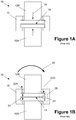
- Figure 1A is a simplistic and schematic representation of a connection made between two hubs so as to describe one problem encountered when using present day connectors.
- the system 10 includes first and second hubs 12A/12B wherein a connector 16 is used to establish a seal 14 between the two hubs 12A/12B.
- the connector 16 is adapted to supply at preload or mating force 18 so as to urge the hubs 12A/12B into sealing engagement with one another.
- a seal (not shown), such as a metal seal, is positioned between the two hubs to effectuate such sealing by causing slight deflection of the seal when the mating force 18 is applied.
- a seal such as a metal seal
- the vertical orientation of the hubs 12A/12B is by way of example only, as they may be oriented in any direction.
- a bending force or load 20 may be applied to one of the hubs 12A/12B.
- the bending force 20 is applied to the top hub 12B.
- the upper hub 12B wants to rotate about the pivot point 21 thereby trying to induce separation (indicated by the double arrows 24) between the two hubs. More specifically, the bending force 20 causes the right side of the connection to experience a compressive force 22C, while the left side of the connection experiences a tensile force 22T.
- the connector 16 and/or portions of the hubs 12A/12B are made exceptionally large and robust so that these bending loads may be resisted and the sealed connection 14 is not lost.
- the connector body must be made sufficiently large and stiff enough so as to withstand all of the loads that it may be reasonably expected to experience during operation, as schematically depicted by the dashed line 26, including the bending force 20.
- using this approach in an effort to account for the bending loads is expensive in that the equipment itself is more expensive and means of handling and positioning such large connectors and hubs in their operating arrangement is more difficult and costly, especially in subsea applications.
- the present disclosure is directed to various embodiment of a connector with actuatable reaction members that may avoid, or at least reduce, the effects of one or more of the problems identified above.
- One device disclosed herein includes, among other things, a body adapted to be positioned adjacent two hubs, primary locking means for connecting the two hubs together and at least one actuatable reaction member that is operatively coupled to the connector body, wherein, when actuated, an inner surface of the at least one actuatable reaction member is urged toward an outer surface of one of the two hubs and wherein a line of travel of the at least one actuatable member is axially spaced apart from a sealing interface that is to be established between the two hubs.
- Another illustrative device disclosed herein includes, among other things, a body adapted to be positioned adjacent two hubs, primary locking means for connecting the two hubs together, at least one actuatable reaction member that is operatively coupled to the connector body, wherein, when actuated, an inner surface of the at least one actuatable reaction member is urged toward an operating position wherein it is positioned adjacent but does not contact an outer surface of one of the two hubs and wherein a line of travel of the at least one actuatable member is axially spaced apart from a sealing interface that is to be established between the two hubs and means for actuating the at least one actuatable reaction member.
- Yet another illustrative device disclosed herein includes, among other things, a body adapted to be positioned adjacent two hubs, primary locking means for connecting the two hubs together, at least one actuatable reaction member that is operatively coupled to the connector body, wherein, when actuated, an inner surface of the at least one actuatable reaction member is urged toward an operating position wherein it abuts and engages an outer surface of one of the two hubs and wherein a line of travel of the at least one actuatable member is axially spaced apart from a sealing interface that is to be established between the two hubs and means for actuating the at least one actuatable reaction member.
- Yet another illustrative device disclosed herein includes, among other things, a body adapted to be positioned adjacent two hubs, primary locking means for connecting the two hubs together and at least one actuatable reaction member that is operatively coupled to the connector body, wherein, when actuated, the at least one actuatable reaction member is urged toward an operating position wherein it abuts and engages both an outer surface of one of the two hubs and an inner surface of the body at a location that is axially spaced apart from a sealing interface that is to be established between the two hubs.
- the present disclosure is generally directed to various embodiments of a connector with at least one actuatable reaction member to resist bending loads and thereby reduce the likelihood of hub separation.
- Figures 2A-2J are simplistic and schematic drawings of a novel connector disclosed herein with one or more actuatable reaction members 130 to resist bending loads.
- the connection 100 includes first and second hubs 112A/112B wherein a connector 116 is used to establish a seal 114 between the two hubs 112A/112B.
- the connector 116 is adapted to supply at preload or mating force 118 so as to urge the hubs 112A/112B into sealing engagement with one another.
- a seal (not shown), such as a metal seal, is positioned between the two hubs to effectuate such sealing by causing slight deflection of the seal when the mating force 118 is applied.
- the connector 116 typically includes a primary locking means (not shown in Figures 2A-2F ), i.e., one or more hydraulic piston(s) and one or more "dogs" that engage a profile, i.e., grooves, formed in the outer surface of the hub 112A.
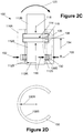
- the connector 116 includes a body 116A that has one or more actuatable reaction members 130 positioned in one or more recesses 116B.
- the actuatable reaction member(s) 130 have an inner surface 130S while the lower hub 112A has an outer surface 112S, e.g., an outer cylindrical surface.
- an actuation force 132 urges the actuatable reaction member(s) 130 toward the outer surface 112S of the lower hub 112A.
- the actuatable reaction member(s) 130 travel radially inward along a line of travel 133 that is axially spaced apart from a sealing interface 135 between the two hubs by a distance 134.
- the magnitude of the distance 134 may vary depending upon the particular application; however, the line of travel 133 should generally be located below the primary locking means 129 to improve reaction to bending moments 120.
- the actuatable reaction member(s) 130 are axially spaced apart from the primary locking interface between the two hubs 112A/112B.
- the actuation force 132 may be applied by any desired means, e.g., hydraulic, pneumatic, mechanical, etc.
- the manner in which components like the novel actuatable reaction member(s) 130 may be urged into a desired operational position are well known to those skilled in the art, e.g., interacting cam surfaces, threaded rods that are rotationally coupled to the one or more actuatable reaction members 130, etc.
- the actuation force 132 may be applied to the actuatable reaction member(s) 130 by means of one or more hydraulic pistons.
- the hydraulic piston(s) used to apply the actuation force 132 may be part of another hydraulic system or it may be part of a dedicated, stand-alone hydraulic system.
- the actuation force 132 may be supplied using a hydraulic piston that is used to actuate the primary locking means (schematically depicted by lines 129 in Figure 2A only) between the hubs 112A/112B.
- the actuation force 132 may be a rotational force applied by a remotely operated vehicle (ROV) or by a human operator.
- ROV remotely operated vehicle
- the recesses 116B for the actuatable reaction member(s) 130 may be integrally formed in the body 116A of the connector 116.
- the recesses 116B for the actuatable reaction member(s) 130 may be formed in a member 137 (depicted in dashed lines in Figure 2A only) that is coupled to the body 116, e.g., by threading, welding, etc.
- the member 137 may be threadingly coupled to the body 116A.
- the actuatable reaction member(s) 130 are considered to be positioned in the body 116A of the connector 116, i.e., the member 137 (when present) is to be considered part of the "body" of the connector 116.
- the actuatable reaction member(s) 130 are in a fully retracted position, i.e., a position when the connector 116 is being initially positioned around the hubs 112A/112B.
- the actuatable reaction member(s) 130 have been urged into a partially extended operating position wherein the inner surface 130S of the actuatable reaction member(s) 130 is positioned adjacent but does not contact the outer surface 112S of the lower hub 112A.
- the magnitude of the spacing between the inner surface 130S actuatable reaction member(s) 130 and the outer surface 112S may vary depending upon the particular application, e.g., 0.005 to 0.060 inches.
- situation depicted in Figure 2B is the position of the actuatable reaction member(s) 130 immediately after installation.
- the various structures depicted Figure 2B may deflect such at least some portion or number of the actuatable reaction member(s) 130 actually engages and abuts the outer surfaces 112S of the lower hub 112A.
- the actuatable reaction member(s) 130 are in a fully extended operational position wherein the inner surface 130S of the actuatable reaction member(s) 130 is purposefully extended to such a distance such that it abuts and engages the outer surface 120S of one of the lower hub 112A.
- the number, size, spacing and configuration of the actuatable reaction member(s) 130 may vary depending upon the particular application.
- the connector disclosed herein employs a single, partial-ring structure, e.g., a C-ring, actuatable reaction member 130.
- the connector 116 employs a plurality of partial-ring structures.
- the actuatable reaction member(s) 130 have an inner surface 130S that has a radius of curvature 130R that is substantially the same as a radius of curvature 112R (see Figure 2C ) of the outer surface 112S of the lower hub 112A.
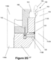
- Figure 2G depicts a particular embodiment of the connector 116 wherein the lower hub 112A is a wellhead.
- the upper hub 112B may be part of any type of structure that is normally coupled to the wellhead, a riser, a Christmas tree, a blowout preventer, etc.
- a hydraulic piston 160 that is used to actuate the primary locking means (schematically depicted by lines 129 in Figure 2A only) between the hubs 112A/112B is also employed to generate the actuation force 132.
- the recesses 116B are formed in a member 137 that is coupled to the body 116A by illustrative threads.
- the primary locking means 161 e.g., dogs
- the piston 160 applies the actuation force 132 by the interaction of cam surfaces on the piston 160 and the actuatable reaction member(s) 130. In the depicted example, this causes the actuatable reaction member(s) 130 to extend and abut and engage the outer surface 112S of the wellhead 112A.
- the connector may be designed such that the piston 160 forces the actuatable reaction member(s) 130 into the above-described partially extended operating position wherein the inner surface 130S of the actuatable reaction member(s) 130 is positioned adjacent but does not contact the outer surface 112S of the lower hub 112A.
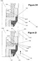
- Figures 2H-2I depict another particular embodiment of the connector 116 wherein the lower hub 112A is a wellhead.
- a second hydraulic piston 170 is also employed to generate the actuation force 132 on the actuatable reaction member(s) 130.
- the actuatable reaction member(s) 130 have a wedge-shaped cross-sectional form.
- the second piston 170 is positioned in the member 137 that is coupled to the body 116A by illustrative threads.
- Figure 2H depicts the connector 116 in the case where the second piston 170 is in a non-actuated state
- Figure 2I depicts the second piston 170 in a fully actuated state
- the primary piston 160 is first fully extended so that the primary locking means 161 (e.g., dogs) are urged into engagement with a profile 163 formed in the outer surface of the wellhead 112A to thereby establish the primary seal between the two components.
- the second piston 170 is actuated such that the piston 170 travels in the direction indicated by the arrow 174.
- the piston 170 engages the bottom surface 130X of the actuatable reaction member(s) 130 thereby forcing the tapered surface 130Y of the actuatable reaction member(s) 130 into engagement with a tapered surface 137X formed on the body 137. i.e., the actuatable reaction member(s) 130 is wedged between the body (137) of the connector and the outer surface 112S of the wellhead 112A.
- the net result of the interaction of the tapered surfaces 130Y and 137X is that an actuation force 132 is generated that causes the inner surface 130S of the actuatable reaction member(s) 130 to abut and engage the outer surface 112S of the wellhead 112A, as shown in Figure 2I .
- the wedged-shaped members 130 could also be urged into a "non-contact" position such as that shown in Figure 2B .
- the wedged shaped member 130 may also take the form of any of the partial rings segments depicted in Figures 2D-2F , and it may also have an inner surface 130S that has a radius of curvature 130R that is substantially the same as a radius of curvature 112R (see Figure 2C ) of the outer surface 112S of the lower hub 112A.
- the wedge-shaped actuatable reaction member 130 is urged toward an operating position wherein it abuts and engages both the outer surface 112S of the hub 112A and the inner surface 137X of the body at a location that is axially spaced apart from a sealing interface that is to be established between the two hubs 112A-112B.
- the inner surface 137X of the body is positioned at an angle relative to the outer surface 112S of the hub 112A.
- Figure 2J depicts yet another particular embodiment of the connector 116 wherein the lower hub 112A is a wellhead.
- the actuatable reaction member(s) 130 are in the form of a threaded rod 138 that is threadingly coupled to the body 116 by the schematically depicted threads 140. Any number of such threaded rods may be positioned around the perimeter of the connector 116.
- one or more of such threaded rods 140 may be rotatably coupled (e.g., a ball and socket arrangement) to the back of each of the actuatable reaction member(s) 130 that are in the form of the partial-ring segments shown in Figures 2D-2F and positioned in recesses 133 formed in the body of the connector.
- the primary piston 160 is first fully extended so that the primary locking means 161 (e.g., dogs) are urged into engagement with a profile 163 formed in the outer surface of the wellhead 112A to thereby establish the primary seal between the two components.
- the threaded rod 140 may be rotated (by any means, such as a human, an ROV, or by any mechanical means) such that the threaded rod 140 is advanced in the direction indicated by the arrow 175.
- the threaded rod 140 is the actuatable reaction member(s) 130
- threaded rod 140 is rotated and advanced until the end or inner surface 140E of the threaded rod 140 abuts and engages the outer surface 112S of the wellhead 112A.
- the threaded rod 140 is rotated and advanced until the inner surface 130S of the partial ring segments abut and engage the outer surface 112S of the wellhead 112A (as shown in Figure 2C ) or until the inner surface 130S of the partial ring segments are positioned a desired distance away from the outer surface (as shown in Figure 2B ).
- the threaded rod 140 arrangement shown in Figure 2J may be readily adapted (e.g., by changing the orientation of the threaded rods) so that one or more of such threaded rods 140 may be used to actuate the wedged-shaped embodiment of the actuatable reaction member shown in Figure 2J .
- a bending force or load 120 may be applied to one of the hubs 112A/112B.
- the bending force 120 is applied to the top hub 112B.
- the upper hub 112B wants to rotate about the pivot point 119 thereby trying to induce separation (indicated by the double arrows 124) between the two hubs 112A/B.
- the connector 116 is stiffer and better able to withstand the additional loading due to the bending load 120.
- the reactionary force 150 is generated upon application of the bending load 120.
- the connector 116 may be made relatively stiffer so as to better withstand and resist the bending loads 120.
- the connector body may be less massive than prior art connector bodies while still providing the required stiffness to resist bending loads.
Landscapes
- Engineering & Computer Science (AREA)
- General Engineering & Computer Science (AREA)
- Mechanical Engineering (AREA)
- Mining & Mineral Resources (AREA)
- Life Sciences & Earth Sciences (AREA)
- Geology (AREA)
- Fluid Mechanics (AREA)
- Environmental & Geological Engineering (AREA)
- Physics & Mathematics (AREA)
- General Life Sciences & Earth Sciences (AREA)
- Geochemistry & Mineralogy (AREA)
- Infusion, Injection, And Reservoir Apparatuses (AREA)
- Quick-Acting Or Multi-Walled Pipe Joints (AREA)
- Connector Housings Or Holding Contact Members (AREA)
Abstract
Description
- The present disclosure generally relates to connectors that are used to establish mating connection between separate hubs, and, more particularly, to a connector with actuatable reaction members to resist bending loads.
- In many industries a sealing connection must be established between two hubs. Broadly speaking, in much application this may be accomplished by use of a connector that contains a locking means for clamping the two hubs together so as to establish the seal between the two hubs. The structures and configurations of the hubs and the connector, as well as the mechanisms used to establish the sealing connection between such hubs is vast and varied. As one example, in the oil and gas industry, subsea wells normally have a large tubular wellhead positioned at the sea floor. A riser that extends from the wellhead to the surface, e.g., to a drill ship or a platform, is used during at least drilling operations. The riser contains a wellhead connector (a first hub) that is adapted to be coupled to the wellhead (a second hub) by the use of a hydraulically actuated connector. Typically, the sealing connection between the two hubs is established by actuating one or more hydraulic cylinders to force "dogs" into engagement with a profile (e.g., grooves) formed in the outer surface of the wellhead. Another example from the oil and gas industry is subsea flow lines wherein connections must be made between two tubular shaped flow lines that carry hydrocarbon fluids and gases. Of course, there are many industrial applications where such connections must be established that are not in a subsea environment, e.g., refineries and petrochemical plants, on-shore drilling operations, etc.
-
Figure 1A is a simplistic and schematic representation of a connection made between two hubs so as to describe one problem encountered when using present day connectors. In general, thesystem 10 includes first andsecond hubs 12A/12B wherein aconnector 16 is used to establish aseal 14 between the twohubs 12A/12B. Theconnector 16 is adapted to supply at preload ormating force 18 so as to urge thehubs 12A/12B into sealing engagement with one another. In one embodiment, a seal (not shown), such as a metal seal, is positioned between the two hubs to effectuate such sealing by causing slight deflection of the seal when themating force 18 is applied. Of course, as will be appreciated by those skilled in the art, there are many forms of hubs, seals and connectors employed within many industries. Moreover, the vertical orientation of thehubs 12A/12B is by way of example only, as they may be oriented in any direction. - With reference to
Figure 1B , during operation, a bending force orload 20 may be applied to one of thehubs 12A/12B. In the depicted example, thebending force 20 is applied to thetop hub 12B. As a result of thebending force 20, theupper hub 12B wants to rotate about thepivot point 21 thereby trying to induce separation (indicated by the double arrows 24) between the two hubs. More specifically, thebending force 20 causes the right side of the connection to experience acompressive force 22C, while the left side of the connection experiences atensile force 22T. - In an effort to account for these
bending loads 20, theconnector 16 and/or portions of thehubs 12A/12B are made exceptionally large and robust so that these bending loads may be resisted and the sealedconnection 14 is not lost. The connector body must be made sufficiently large and stiff enough so as to withstand all of the loads that it may be reasonably expected to experience during operation, as schematically depicted by thedashed line 26, including thebending force 20. However, using this approach in an effort to account for the bending loads is expensive in that the equipment itself is more expensive and means of handling and positioning such large connectors and hubs in their operating arrangement is more difficult and costly, especially in subsea applications. - The present disclosure is directed to various embodiment of a connector with actuatable reaction members that may avoid, or at least reduce, the effects of one or more of the problems identified above.
- The following presents a simplified summary of the invention in order to provide a basic understanding of some aspects of the invention. This summary is not an exhaustive overview of the invention. It is not intended to identify key or critical elements of the invention or to delineate the scope of the invention. Its sole purpose is to present some concepts in a simplified form as a prelude to the more detailed description that is discussed later.
- Generally, the present disclosure is directed to various embodiments of a connector with actuatable reaction members to resist bending loads. One device disclosed herein includes, among other things, a body adapted to be positioned adjacent two hubs, primary locking means for connecting the two hubs together and at least one actuatable reaction member that is operatively coupled to the connector body, wherein, when actuated, an inner surface of the at least one actuatable reaction member is urged toward an outer surface of one of the two hubs and wherein a line of travel of the at least one actuatable member is axially spaced apart from a sealing interface that is to be established between the two hubs.
- Another illustrative device disclosed herein includes, among other things, a body adapted to be positioned adjacent two hubs, primary locking means for connecting the two hubs together, at least one actuatable reaction member that is operatively coupled to the connector body, wherein, when actuated, an inner surface of the at least one actuatable reaction member is urged toward an operating position wherein it is positioned adjacent but does not contact an outer surface of one of the two hubs and wherein a line of travel of the at least one actuatable member is axially spaced apart from a sealing interface that is to be established between the two hubs and means for actuating the at least one actuatable reaction member.
- Yet another illustrative device disclosed herein includes, among other things, a body adapted to be positioned adjacent two hubs, primary locking means for connecting the two hubs together, at least one actuatable reaction member that is operatively coupled to the connector body, wherein, when actuated, an inner surface of the at least one actuatable reaction member is urged toward an operating position wherein it abuts and engages an outer surface of one of the two hubs and wherein a line of travel of the at least one actuatable member is axially spaced apart from a sealing interface that is to be established between the two hubs and means for actuating the at least one actuatable reaction member.
- Yet another illustrative device disclosed herein includes, among other things, a body adapted to be positioned adjacent two hubs, primary locking means for connecting the two hubs together and at least one actuatable reaction member that is operatively coupled to the connector body, wherein, when actuated, the at least one actuatable reaction member is urged toward an operating position wherein it abuts and engages both an outer surface of one of the two hubs and an inner surface of the body at a location that is axially spaced apart from a sealing interface that is to be established between the two hubs.
- The disclosure may be understood by reference to the following description taken in conjunction with the accompanying drawings, in which like reference numerals identify like elements, and in which:
-
Figures 1A-1B are simplistic and schematic drawings of a prior art connector that is used to establish a sealed connection between two hubs; and -
Figures 2A-2J are simplistic and schematic drawings of a novel connector disclosed herein with one or more actuatable reaction members to resist bending loads and thereby reduce the likelihood of hub separation. - While the subject matter disclosed herein is susceptible to various modifications and alternative forms, specific embodiments thereof have been shown by way of example in the drawings and are herein described in detail. It should be understood, however, that the description herein of specific embodiments is not intended to limit the invention to the particular forms disclosed, but on the contrary, the intention is to cover all modifications, equivalents, and alternatives falling within the spirit and scope of the invention as defined by the appended claims.
- Various illustrative embodiments of the invention are described below. In the interest of clarity, not all features of an actual implementation are described in this specification. It will of course be appreciated that in the development of any such actual embodiment, numerous implementation-specific decisions must be made to achieve the developers' specific goals, such as compliance with system-related and business-related constraints, which will vary from one implementation to another. Moreover, it will be appreciated that such a development effort might be complex and time-consuming, but would nevertheless be a routine undertaking for those of ordinary skill in the art having the benefit of this disclosure.
- The present subject matter will now be described with reference to the attached figures. Various structures, systems and devices are schematically depicted in the drawings for purposes of explanation only and so as to not obscure the present disclosure with details that are well known to those skilled in the art. Nevertheless, the attached drawings are included to describe and explain illustrative examples of the present disclosure. The words and phrases used herein should be understood and interpreted to have a meaning consistent with the understanding of those words and phrases by those skilled in the relevant art. No special definition of a term or phrase, i.e., a definition that is different from the ordinary and customary meaning as understood by those skilled in the art, is intended to be implied by consistent usage of the term or phrase herein. To the extent that a term or phrase is intended to have a special meaning, i.e., a meaning other than that understood by skilled artisans, such a special definition will be expressly set forth in the specification in a definitional manner that directly and unequivocally provides the special definition for the term or phrase.
- The present disclosure is generally directed to various embodiments of a connector with at least one actuatable reaction member to resist bending loads and thereby reduce the likelihood of hub separation. With reference to the attached figures, various illustrative embodiments of the methods and devices disclosed herein will now be described in more detail.
-
Figures 2A-2J are simplistic and schematic drawings of a novel connector disclosed herein with one or moreactuatable reaction members 130 to resist bending loads. In general, theconnection 100 includes first andsecond hubs 112A/112B wherein aconnector 116 is used to establish aseal 114 between the twohubs 112A/112B. Theconnector 116 is adapted to supply at preload ormating force 118 so as to urge thehubs 112A/112B into sealing engagement with one another. In one embodiment, a seal (not shown), such as a metal seal, is positioned between the two hubs to effectuate such sealing by causing slight deflection of the seal when themating force 118 is applied. Of course, as will be appreciated by those skilled in the art, there are many forms of hubs, seals and connectors employed within many industries. Thus, the presently disclosed inventions should not be considered to be limited to any particular type of industry, application or devices. Moreover, the vertical orientation of thehubs 112A/112B is by way of example only, as they may be oriented in any direction. Theconnector 116 typically includes a primary locking means (not shown inFigures 2A-2F ), i.e., one or more hydraulic piston(s) and one or more "dogs" that engage a profile, i.e., grooves, formed in the outer surface of thehub 112A. - In general, the
connector 116 includes abody 116A that has one or moreactuatable reaction members 130 positioned in one ormore recesses 116B. As will be more fully discussed below, the number, size, spacing and configuration of the actuatable reaction member(s) 130 may vary depending upon the particular application. The actuatable reaction member(s) 130 have aninner surface 130S while thelower hub 112A has anouter surface 112S, e.g., an outer cylindrical surface. In general, anactuation force 132 urges the actuatable reaction member(s) 130 toward theouter surface 112S of thelower hub 112A. In one embodiment, the actuatable reaction member(s) 130 travel radially inward along a line oftravel 133 that is axially spaced apart from a sealinginterface 135 between the two hubs by adistance 134. The magnitude of thedistance 134 may vary depending upon the particular application; however, the line oftravel 133 should generally be located below the primary locking means 129 to improve reaction to bendingmoments 120. In the depicted example, the actuatable reaction member(s) 130 are axially spaced apart from the primary locking interface between the twohubs 112A/112B. - The
actuation force 132 may be applied by any desired means, e.g., hydraulic, pneumatic, mechanical, etc. The manner in which components like the novel actuatable reaction member(s) 130 may be urged into a desired operational position are well known to those skilled in the art, e.g., interacting cam surfaces, threaded rods that are rotationally coupled to the one or moreactuatable reaction members 130, etc. In one example, theactuation force 132 may be applied to the actuatable reaction member(s) 130 by means of one or more hydraulic pistons. The hydraulic piston(s) used to apply theactuation force 132 may be part of another hydraulic system or it may be part of a dedicated, stand-alone hydraulic system. In one particular embodiment, theactuation force 132 may be supplied using a hydraulic piston that is used to actuate the primary locking means (schematically depicted bylines 129 inFigure 2A only) between thehubs 112A/112B. In other applications, theactuation force 132 may be a rotational force applied by a remotely operated vehicle (ROV) or by a human operator. In one example, therecesses 116B for the actuatable reaction member(s) 130 may be integrally formed in thebody 116A of theconnector 116. In another example, therecesses 116B for the actuatable reaction member(s) 130 may be formed in a member 137 (depicted in dashed lines inFigure 2A only) that is coupled to thebody 116, e.g., by threading, welding, etc. For example, in some cases, after the connector is positioned thehubs 112A/B, themember 137 may be threadingly coupled to thebody 116A. Under either situation, the actuatable reaction member(s) 130 are considered to be positioned in thebody 116A of theconnector 116, i.e., the member 137 (when present) is to be considered part of the "body" of theconnector 116. - In the situation depicted in
Figure 2A , the actuatable reaction member(s) 130 are in a fully retracted position, i.e., a position when theconnector 116 is being initially positioned around thehubs 112A/112B. In the situation depicted inFigure 2B , the actuatable reaction member(s) 130 have been urged into a partially extended operating position wherein theinner surface 130S of the actuatable reaction member(s) 130 is positioned adjacent but does not contact theouter surface 112S of thelower hub 112A. The magnitude of the spacing between theinner surface 130S actuatable reaction member(s) 130 and theouter surface 112S may vary depending upon the particular application, e.g., 0.005 to 0.060 inches. Note that situation depicted inFigure 2B is the position of the actuatable reaction member(s) 130 immediately after installation. In operation, when theconnector 116 is subjected to a bending load, the various structures depictedFigure 2B may deflect such at least some portion or number of the actuatable reaction member(s) 130 actually engages and abuts theouter surfaces 112S of thelower hub 112A. In the situation depicted inFigure 2C , the actuatable reaction member(s) 130 are in a fully extended operational position wherein theinner surface 130S of the actuatable reaction member(s) 130 is purposefully extended to such a distance such that it abuts and engages the outer surface 120S of one of thelower hub 112A. - As indicated above, the number, size, spacing and configuration of the actuatable reaction member(s) 130 may vary depending upon the particular application. In the embodiment depicted in
Figure 2D , the connector disclosed herein employs a single, partial-ring structure, e.g., a C-ring,actuatable reaction member 130. In the embodiments shown inFigures 2E and 2F , theconnector 116 employs a plurality of partial-ring structures. In some embodiments, the actuatable reaction member(s) 130 have aninner surface 130S that has a radius ofcurvature 130R that is substantially the same as a radius ofcurvature 112R (seeFigure 2C ) of theouter surface 112S of thelower hub 112A. -
Figure 2G depicts a particular embodiment of theconnector 116 wherein thelower hub 112A is a wellhead. Theupper hub 112B may be part of any type of structure that is normally coupled to the wellhead, a riser, a Christmas tree, a blowout preventer, etc. In this example, ahydraulic piston 160 that is used to actuate the primary locking means (schematically depicted bylines 129 inFigure 2A only) between thehubs 112A/112B is also employed to generate theactuation force 132. In this example, therecesses 116B are formed in amember 137 that is coupled to thebody 116A by illustrative threads. In operation, as thepiston 160 is urged downward in the direction indicated by thearrow 162, the primary locking means 161 (e.g., dogs) are urged into engagement with aprofile 163 formed in the outer surface of thewellhead 112A by the interaction of various cam surfaces. As thepiston 160 continues with further downward travel, thepiston 160 applies theactuation force 132 by the interaction of cam surfaces on thepiston 160 and the actuatable reaction member(s) 130. In the depicted example, this causes the actuatable reaction member(s) 130 to extend and abut and engage theouter surface 112S of thewellhead 112A. Of course, the connector may be designed such that thepiston 160 forces the actuatable reaction member(s) 130 into the above-described partially extended operating position wherein theinner surface 130S of the actuatable reaction member(s) 130 is positioned adjacent but does not contact theouter surface 112S of thelower hub 112A. -
Figures 2H-2I depict another particular embodiment of theconnector 116 wherein thelower hub 112A is a wellhead. In this example, in addition to thehydraulic piston 160 that is used to actuate the primary locking means between thehubs 112A/112B, a secondhydraulic piston 170 is also employed to generate theactuation force 132 on the actuatable reaction member(s) 130. In this example, the actuatable reaction member(s) 130 have a wedge-shaped cross-sectional form. Thesecond piston 170 is positioned in themember 137 that is coupled to thebody 116A by illustrative threads.Figure 2H depicts theconnector 116 in the case where thesecond piston 170 is in a non-actuated state, whileFigure 2I depicts thesecond piston 170 in a fully actuated state. In operation, theprimary piston 160 is first fully extended so that the primary locking means 161 (e.g., dogs) are urged into engagement with aprofile 163 formed in the outer surface of thewellhead 112A to thereby establish the primary seal between the two components. At some time thereafter, thesecond piston 170 is actuated such that thepiston 170 travels in the direction indicated by thearrow 174. As thepiston 170 continues further upward travel, thepiston 170 engages thebottom surface 130X of the actuatable reaction member(s) 130 thereby forcing the taperedsurface 130Y of the actuatable reaction member(s) 130 into engagement with atapered surface 137X formed on thebody 137. i.e., the actuatable reaction member(s) 130 is wedged between the body (137) of the connector and theouter surface 112S of thewellhead 112A. The net result of the interaction of the taperedsurfaces actuation force 132 is generated that causes theinner surface 130S of the actuatable reaction member(s) 130 to abut and engage theouter surface 112S of thewellhead 112A, as shown inFigure 2I . If desired, the wedged-shapedmembers 130 could also be urged into a "non-contact" position such as that shown inFigure 2B . The wedgedshaped member 130 may also take the form of any of the partial rings segments depicted inFigures 2D-2F , and it may also have aninner surface 130S that has a radius ofcurvature 130R that is substantially the same as a radius ofcurvature 112R (seeFigure 2C ) of theouter surface 112S of thelower hub 112A. As depicted, in this embodiment the wedge-shapedactuatable reaction member 130 is urged toward an operating position wherein it abuts and engages both theouter surface 112S of thehub 112A and theinner surface 137X of the body at a location that is axially spaced apart from a sealing interface that is to be established between the twohubs 112A-112B. Theinner surface 137X of the body is positioned at an angle relative to theouter surface 112S of thehub 112A. -
Figure 2J depicts yet another particular embodiment of theconnector 116 wherein thelower hub 112A is a wellhead. In one example, the actuatable reaction member(s) 130 are in the form of a threadedrod 138 that is threadingly coupled to thebody 116 by the schematically depictedthreads 140. Any number of such threaded rods may be positioned around the perimeter of theconnector 116. In another embodiment (depicted in dashed lines inFigure 2J ) one or more of such threadedrods 140 may be rotatably coupled (e.g., a ball and socket arrangement) to the back of each of the actuatable reaction member(s) 130 that are in the form of the partial-ring segments shown inFigures 2D-2F and positioned inrecesses 133 formed in the body of the connector. In operation, theprimary piston 160 is first fully extended so that the primary locking means 161 (e.g., dogs) are urged into engagement with aprofile 163 formed in the outer surface of thewellhead 112A to thereby establish the primary seal between the two components. As some time thereafter, the threadedrod 140 may be rotated (by any means, such as a human, an ROV, or by any mechanical means) such that the threadedrod 140 is advanced in the direction indicated by thearrow 175. In the case where the threadedrod 140 is the actuatable reaction member(s) 130, threadedrod 140 is rotated and advanced until the end orinner surface 140E of the threadedrod 140 abuts and engages theouter surface 112S of thewellhead 112A. In the case where one or more of the threadedrods 140 is rotatably coupled to the actuatable reaction member(s) 130 in the form of partial ring segments, the threadedrod 140 is rotated and advanced until theinner surface 130S of the partial ring segments abut and engage theouter surface 112S of thewellhead 112A (as shown inFigure 2C ) or until theinner surface 130S of the partial ring segments are positioned a desired distance away from the outer surface (as shown inFigure 2B ). Of course, in lieu of thepiston 170, the threadedrod 140 arrangement shown inFigure 2J may be readily adapted (e.g., by changing the orientation of the threaded rods) so that one or more of such threadedrods 140 may be used to actuate the wedged-shaped embodiment of the actuatable reaction member shown inFigure 2J . - With reference to
Figures 2B and2C , during operation, a bending force or load 120 may be applied to one of thehubs 112A/112B. In the depicted example, the bendingforce 120 is applied to thetop hub 112B. As a result of the bendingforce 120, theupper hub 112B wants to rotate about thepivot point 119 thereby trying to induce separation (indicated by the double arrows 124) between the twohubs 112A/B. However, due to the presence of the novel actuatable reaction member(s) 130, theconnector 116 is stiffer and better able to withstand the additional loading due to thebending load 120. More specifically, in the case where theactuatable reaction members 130 are positioned in the manner depicted inFigure 2B , upon deflection of some of the components of theconnector 116 and or thehubs 112A/112B, at least some portion or number of the actuatable reaction member(s) 130 actually engages and abuts theouter surfaces 112S of thelower hub 112A thereby generating a reactionary force 150 (seeFigure 2B ) at adistance 134 that tend to counteract or resist the bendingforce 120. In the situation depicted inFigure 2C , where theinner surface 130S of the actuatable reaction member(s) 130 is purposefully positioned so as to abut and engage the outer surface 120S of thelower hub 112A, thereactionary force 150 is generated upon application of the bendingload 120. Thus, through use of thenovel connector 116 disclosed herein, including the one or moreactuatable reaction members 130, theconnector 116 may be made relatively stiffer so as to better withstand and resist the bending loads 120. Additionally, due to the novel aspects of the connector disclosed herein, the connector body may be less massive than prior art connector bodies while still providing the required stiffness to resist bending loads. It should also be noted that, due to the presence of the actuatable reaction member(s) 130, the load distribution in theconnector 116, as depicted by the dashedlines Figure 2C , is more disbursed as compared to theload distribution 26 for theprior art connector 10 shown inFigure 1B . - The particular embodiments disclosed above are illustrative only, as the invention may be modified and practiced in different but equivalent manners apparent to those skilled in the art having the benefit of the teachings herein. For example, the process steps set forth above may be performed in a different order. Furthermore, no limitations are intended to the details of construction or design herein shown, other than as described in the claims below. It is therefore evident that the particular embodiments disclosed above may be altered or modified and all such variations are considered within the scope and spirit of the invention. Note that the use of terms, such as "first," "second," "third" or "fourth" to describe various processes or structures in this specification and in the attached claims is only used as a shorthand reference to such steps/structures and does not necessarily imply that such steps/structures are performed/formed in that ordered sequence. Of course, depending upon the exact claim language, an ordered sequence of such processes may or may not be required. Accordingly, the protection sought herein is as set forth in the appended claims.
- Further illustrative examples of the invention are given as follows:
- Example 1. A connector that is adapted to establish a sealed connection between two hubs, the connector, comprising:
- a body adapted to be positioned adjacent the two hubs;
- primary locking means for connecting the two hubs together; and
- at least one actuatable reaction member that is operatively coupled to the connector body, wherein, when actuated, an inner surface of the at least one actuatable reaction member is urged toward an outer surface of one of the two hubs and wherein a line of travel of the at least one actuatable member is axially spaced apart from a sealing interface that is to be established between the two hubs.
- Example 2. The connector of example 1, wherein the at least one actuatable reaction member has one of a partial-ring structure or a threaded rod structure.
- Example 3. The connector of example 2, wherein the at least one actuatable reaction member is positioned in a recess formed in the body.
- Example 4. The connector of example 1, wherein the at least one actuatable reaction member is adapted to be wedged between an inner surface of the body and the outer surface of one of the two hubs.
- Example 5. The connector of example 1, wherein the at least one actuatable reaction member comprises a plurality of actuatable reaction members.
- Example 6. The connector of example 5, wherein the plurality of actuatable reaction members are spaced-apart partial-ring segments.
- Example 7. The connector of example 1, wherein the inner surface of the at least one actuatable reaction member has a radius of curvature that is substantially the same as a radius of curvature of the outer surface of one of the two hubs.
- Example 8. The connector of example 1, wherein, when actuated, the inner surface of the at least one actuatable reaction member is urged toward an operating position wherein it is positioned adjacent but does not contact the outer surface of one of the two hubs.
- Example 9. The connector of example 1, wherein, when actuated, the inner surface of the at least one actuatable reaction member is urged toward an operating position wherein it abuts and engages the outer surface of one of the two apart hubs.
- Example 10. The connector of example 1, further comprising means for actuating the at least one acutatable reaction member.
- Example 11. The connector of example 10, wherein the means for actuating the at least one actuatable member comprises a hydraulic piston.
- Example 12. The connector of example 10, wherein the means for actuating the at least one actuatable member comprises a threaded rod that is threadingly coupled to the body.
- Example 13. The connector of example 1, further comprising at least one dedicated hydraulic piston that is adapted to actuate the at least one actuatable reaction member.
- Example 14. The connector of example 1, further comprising at least one a threaded rod that is adapted to actuate the at least one actuatable reaction member, wherein the at least one threaded rod is threadingly coupled to the body and rotatably coupled to the at least one actuatable reaction member.
- Example 15. The connector of example 1, further comprising at least one hydraulic piston that is adapted to actuate both the primary locking means and the at least one actuatable reaction member.
- Example 16. A connector that is adapted to establish a sealed connection between two hubs, the connector, comprising:
- a body adapted to be positioned adjacent the two hubs;
- primary locking means for connecting the two hubs together;
- at least one actuatable reaction member that is operatively coupled to the connector body, wherein, when actuated, an inner surface of the at least one actuatable reaction member is urged toward an operating position wherein it is positioned adjacent but does not contact an outer surface of one of the two hubs and wherein a line of travel of the at least one actuatable member is axially spaced apart from a sealing interface that is to be established between the two hubs; and
- means for actuating the at least one actuatable reaction member.
- Example 17. The connector of example 16, wherein the at least one actuatable reaction member has one of a partial-ring structure or a threaded rod structure.
- Example 18. The connector of example 16, wherein the at least one actuatable reaction member is adapted to be wedged between an inner surface of the body and the outer surface of one of the two hubs.
- Example 19. The connector of example 16, wherein the at least one actuatable reaction member comprises a plurality of actuatable reaction members.
- Example 20. The connector of example 19, wherein the plurality of actuatable reaction members are spaced-apart partial-ring segments.
- Example 21. The connector of example 16, wherein the inner surface of the at least one actuatable reaction member has a radius of curvature that is substantially the same as a radius of curvature of the outer surface of one of the two hubs.
- Example 22. The connector of example 16, wherein the means for actuating the at least one actuatable reaction member is further adapted to actuate the primary locking means.
- Example 23. A connector that is adapted to establish a sealed connection between two hubs, the connector, comprising:
- a body adapted to be positioned adjacent the two hubs;
- primary locking means for connecting the two hubs together;
- at least one actuatable reaction member that is operatively coupled to the connector body, wherein, when actuated, an inner surface of the at least one actuatable reaction member is urged toward an operating position wherein it abuts and engages an outer surface of one of the two hubs and wherein a line of travel of the at least one actuatable member is axially spaced apart from a sealing interface that is to be established between the two hubs; and
- means for actuating the at least one actuatable reaction member.
- Example 24. The connector of example 23, wherein the at least one actuatable reaction member has one of a partial-ring structure or a threaded rod structure.
- Example 25. The connector of example 23, wherein the at least one actuatable reaction member is adapted to be wedged between the body and the outer surface of one of the two hubs.
- Example 26. The connector of example 23, wherein the at least one actuatable reaction member comprises a plurality of actuatable reaction members.
- Example 27. The connector of example 26, wherein the plurality of actuatable reaction members are spaced-apart partial-ring segments.
- Example 28. The connector of example 23, wherein the inner surface of the at least one actuatable reaction member has a radius of curvature that is substantially the same as a radius of curvature of the outer surface of one of the two hubs.
- Example 29. A connector that is adapted to establish a sealed connection between two hubs, the connector, comprising:
- a body adapted to be positioned adjacent the two hubs;
- primary locking means for connecting the two hubs together; and
- at least one actuatable reaction member that is operatively coupled to the connector body, wherein, when actuated, the at least one actuatable reaction member is urged toward an operating position wherein it abuts and engages both an outer surface of one of the two hubs and an inner surface of the body at a location that is axially spaced apart from a sealing interface that is to be established between the two hubs.
- Example 30. The connector of example 29, wherein the at least one actuatable reaction member has one of a partial-ring structure.
- Example 31. The connector of example 29, wherein the inner surface of the body is positioned at an angle relative to the outer surface.
- Example 32. The connector of example 29, wherein the at least one actuatable reaction member comprises a plurality of actuatable reaction members.
- Example 33. The connector of example 29, wherein the plurality of actuatable reaction members are spaced-apart partial-ring segments.
- Example 34. The connector of example 29, wherein the inner surface of the at least one actuatable reaction member has a radius of curvature that is substantially the same as a radius of curvature of the outer surface.
- Example 35. The connector of example 29, further comprising means for actuating the at least one actuatable reaction member.
- Example 36. The connector of example 35, wherein the means for actuating the at least one actuatable member comprises a hydraulic piston.
- Example 37. The connector of example 35, wherein the means for actuating the at least one actuatable member comprises a threaded rod that is threadingly coupled to the body.
- Example 38. The connector of example 29, further comprising at least one dedicated hydraulic piston that is adapted to actuate the at least one actuatable reaction member.
- Example 39. The connector of example 29, further comprising at least one a threaded rod that is adapted to actuate the at least one actuatable reaction member, wherein the at least one threaded rod is threadingly coupled to the body and rotatably coupled to the at least one actuatable reaction member.
- Example 40. The connector of example 29, further comprising at least one hydraulic piston that is adapted to actuate both the primary locking means and the at least one actuatable reaction member.
Claims (15)
- A connector (116) that is adapted to establish a sealed connection between a first hub (112A) and a second hub (112B), the connector (116) comprising:a body (116A) that is adapted to be positioned around and adjacent to the first and second hubs (112A, 112B);primary locking means (129) for connecting the first hub (112A) to the second hub (112B);at least one actuatable reaction member (130) that is operatively coupled to the connector body (116A), the at least one actuatable reaction member (130) having an inner surface (130S) that is adapted to engage and contact an outer surface (112S) of the first hub (112A), wherein a radial line of travel (133) of the at least one actuatable member (130) is axially spaced apart from a sealing interface (135) between the first and second hubs (112A, 112B); andactuating means for actuating the at least one actuatable reaction member (130), wherein the actuating means is adapted to engage an outer surface of the at least one actuatable reaction member (130), to move the at least one actuatable reaction member (130) radially inward to an extended position, and to restrain the at least one actuatable reaction member (130) against radially outward movement from the extended position.
- The connector of claim 1, wherein the at least one actuatable reaction member (130) has a partial-ring structure.
- The connector of claim 1 or claim 2, wherein the at least one actuatable reaction member (130) is positioned in a recess (116B) formed in the body (116A).
- The connector of any one of claims 1-3, wherein the at least one actuatable reaction member (130) is adapted to be wedged between an inner surface of the body and the outer surface (112S) of the first hub (112A).
- The connector of any one of claims 1-4, wherein the at least one actuatable reaction member (130) comprises a plurality of actuatable reaction members (130).
- The connector of claim 5, wherein the plurality of actuatable reaction members (130) are spaced-apart partial-ring segments.
- The connector of any one of claims 1-4, wherein the inner surface (130S) of the at least one actuatable reaction member (130) has a radius of curvature (130R) that is substantially the same as a radius of curvature (112R) of the outer surface (112S) of the first hub (112A).
- The connector of any one of claims 1-4 or 7, wherein, when actuated by the actuating means, the inner surface (130S) of the at least one actuatable reaction member (130) is urged toward an operating position adjacent to, but not in contact with, the outer surface (112S) of the first hub (112A).
- The connector of any one of claims 1-4, 7 or 8, wherein, when actuated, the inner surface (112S) of the at least one actuatable reaction member (130) is urged toward an operating position wherein it abuts and contactingly engages the outer surface (112S) of the first hub (112A).
- The connector of any one of claims 1-4 or 7-9, wherein the actuating means comprises at least one hydraulic piston.
- The connector of claim 10, wherein the at least one hydraulic piston is a single hydraulic piston (160) that is adapted to actuate both the primary locking means (129) and the at least one actuatable reaction member (130).
- The connector of claim 10, wherein the at least one actuatable reaction member (130) comprises a plurality of actuatable reaction members (130).
- The connector of claim 12, wherein the at least one hydraulic piston is a dedicated hydraulic piston (170) that is adapted to only actuate the plurality of actuatable reaction members (130).
- The connector of any one of claims 1-4 or 7-9, wherein the actuating means comprises a threaded rod (138) that is threadingly coupled to the body (116A).
- The connector of claim 14, wherein the at least one threaded rod (138) is rotatably coupled to the at least one actuatable reaction member (130).
Priority Applications (1)
| Application Number | Priority Date | Filing Date | Title |
|---|---|---|---|
| EP18157486.4A EP3346089B1 (en) | 2014-03-31 | 2014-03-31 | Connector with actuatable reaction members to resist bending loads |
Applications Claiming Priority (3)
| Application Number | Priority Date | Filing Date | Title |
|---|---|---|---|
| EP18157486.4A EP3346089B1 (en) | 2014-03-31 | 2014-03-31 | Connector with actuatable reaction members to resist bending loads |
| EP14730621.1A EP3126618B1 (en) | 2014-03-31 | 2014-03-31 | Connector with actuatable reaction members to resist bending loads |
| PCT/US2014/032411 WO2015152886A1 (en) | 2014-03-31 | 2014-03-31 | Connector with actuatable reaction members to resist bending loads |
Related Parent Applications (2)
| Application Number | Title | Priority Date | Filing Date |
|---|---|---|---|
| EP14730621.1A Division EP3126618B1 (en) | 2014-03-31 | 2014-03-31 | Connector with actuatable reaction members to resist bending loads |
| EP14730621.1A Division-Into EP3126618B1 (en) | 2014-03-31 | 2014-03-31 | Connector with actuatable reaction members to resist bending loads |
Publications (2)
| Publication Number | Publication Date |
|---|---|
| EP3346089A1 true EP3346089A1 (en) | 2018-07-11 |
| EP3346089B1 EP3346089B1 (en) | 2020-04-29 |
Family
ID=50943528
Family Applications (2)
| Application Number | Title | Priority Date | Filing Date |
|---|---|---|---|
| EP14730621.1A Active EP3126618B1 (en) | 2014-03-31 | 2014-03-31 | Connector with actuatable reaction members to resist bending loads |
| EP18157486.4A Active EP3346089B1 (en) | 2014-03-31 | 2014-03-31 | Connector with actuatable reaction members to resist bending loads |
Family Applications Before (1)
| Application Number | Title | Priority Date | Filing Date |
|---|---|---|---|
| EP14730621.1A Active EP3126618B1 (en) | 2014-03-31 | 2014-03-31 | Connector with actuatable reaction members to resist bending loads |
Country Status (6)
| Country | Link |
|---|---|
| US (2) | US10082231B2 (en) |
| EP (2) | EP3126618B1 (en) |
| BR (2) | BR112016022687B1 (en) |
| NO (1) | NO3126618T3 (en) |
| SG (1) | SG11201606957WA (en) |
| WO (1) | WO2015152886A1 (en) |
Families Citing this family (2)
| Publication number | Priority date | Publication date | Assignee | Title |
|---|---|---|---|---|
| US9334705B1 (en) * | 2015-01-13 | 2016-05-10 | Onesubsea Ip Uk Limited | Subsea connector |
| CN110094178B (en) * | 2019-05-31 | 2024-06-07 | 中国石油集团川庆钻探工程有限公司 | Wellhead resetting device and resetting method suitable for bottomed flange |
Citations (3)
| Publication number | Priority date | Publication date | Assignee | Title |
|---|---|---|---|---|
| US3333870A (en) * | 1965-12-30 | 1967-08-01 | Regan Forge & Eng Co | Marine conductor coupling with double seal construction |
| US4902045A (en) * | 1986-12-18 | 1990-02-20 | Hunting Oilfield Services Limited | Connectors |
| US20050001427A1 (en) * | 2003-05-20 | 2005-01-06 | Fmc Technologies, Inc. | Low profile connector |
Family Cites Families (25)
| Publication number | Priority date | Publication date | Assignee | Title |
|---|---|---|---|---|
| US807739A (en) * | 1905-08-17 | 1905-12-19 | Jacob Patrick Hanson | Leak-stopping gland. |
| US2410589A (en) * | 1942-08-17 | 1946-11-05 | August L Segelhorst | Automatic slip mechanism |
| US2737248A (en) * | 1950-07-10 | 1956-03-06 | Baker Oil Tools Inc | Nonrotary threaded coupling |
| US2994381A (en) * | 1958-10-24 | 1961-08-01 | Cicero C Brown | Liner setting assembly |
| US3090640A (en) * | 1959-05-04 | 1963-05-21 | Shell Oil Co | Well casing and tubing suspension assembly |
| US4124233A (en) * | 1977-05-04 | 1978-11-07 | Vetco, Inc. | Rigid pipe connector with lock ring and method of making the same |
| US4433859A (en) * | 1981-07-16 | 1984-02-28 | Nl Industries, Inc. | Wellhead connector with release mechanism |
| US4526406A (en) * | 1981-07-16 | 1985-07-02 | Nelson Norman A | Wellhead connector |
| US4771832A (en) * | 1987-12-09 | 1988-09-20 | Vetco Gray Inc. | Wellhead with eccentric casing seal ring |
| US4902044A (en) * | 1989-05-04 | 1990-02-20 | Drill-Quip, Inc. | Well apparatus |
| GB8914931D0 (en) * | 1989-06-29 | 1989-08-23 | Plexus Ocean Syst Ltd | A releasable connector |
| US5205356A (en) * | 1990-12-27 | 1993-04-27 | Abb Vetco Gray Inc. | Well starter head |
| US5299644A (en) * | 1990-12-27 | 1994-04-05 | Abb Vetco Gray Inc. | Well starter head |
| US6035938A (en) | 1998-03-26 | 2000-03-14 | Dril-Quip, Inc. | Wellhead system and method for use in drilling a subsea well |
| US6662868B1 (en) * | 2000-05-03 | 2003-12-16 | Bernard H. Van Bilderbeek | Clamping well casings |
| US7322407B2 (en) * | 2002-02-19 | 2008-01-29 | Duhn Oil Tool, Inc. | Wellhead isolation tool and method of fracturing a well |
| US7128143B2 (en) * | 2003-12-31 | 2006-10-31 | Plexus Ocean Systems Ltd. | Externally activated seal system for wellhead |
| US8066064B2 (en) * | 2008-11-12 | 2011-11-29 | Vetco Gray Inc. | Well assembly having a casing hanger supported by a load member actuated by a retractable member disposed in the wellhead |
| US8388255B2 (en) * | 2009-07-13 | 2013-03-05 | Vetco Gray Inc. | Dog-type lockout and position indicator assembly |
| US8347970B2 (en) * | 2009-10-26 | 2013-01-08 | Cameron International Corporation | Wellhead tubular connector |
| GB2479552B (en) * | 2010-04-14 | 2015-07-08 | Aker Subsea Ltd | Subsea wellhead providing controlled access to a casing annulus |
| CA2752931C (en) * | 2010-09-22 | 2015-09-08 | Stream-Flo Industries Ltd. | Wellhead seal device to seal casing |
| US8978772B2 (en) * | 2011-12-07 | 2015-03-17 | Vetco Gray Inc. | Casing hanger lockdown with conical lockdown ring |
| BR112014024680B1 (en) * | 2012-04-05 | 2020-12-01 | National Oilwell Varco, L.P. | well location connector, and, method for connecting components from a well location |
| US10113383B2 (en) * | 2012-05-10 | 2018-10-30 | Vetco Gray, LLC | Positive retention lock ring for tubing hanger |
-
2014
- 2014-03-31 NO NO14730621A patent/NO3126618T3/no unknown
- 2014-03-31 EP EP14730621.1A patent/EP3126618B1/en active Active
- 2014-03-31 EP EP18157486.4A patent/EP3346089B1/en active Active
- 2014-03-31 WO PCT/US2014/032411 patent/WO2015152886A1/en not_active Ceased
- 2014-03-31 BR BR112016022687-9A patent/BR112016022687B1/en active IP Right Grant
- 2014-03-31 SG SG11201606957WA patent/SG11201606957WA/en unknown
- 2014-03-31 BR BR122020015732-1A patent/BR122020015732B1/en active IP Right Grant
- 2014-03-31 US US15/122,735 patent/US10082231B2/en active Active
-
2018
- 2018-08-21 US US16/106,433 patent/US20180356018A1/en not_active Abandoned
Patent Citations (3)
| Publication number | Priority date | Publication date | Assignee | Title |
|---|---|---|---|---|
| US3333870A (en) * | 1965-12-30 | 1967-08-01 | Regan Forge & Eng Co | Marine conductor coupling with double seal construction |
| US4902045A (en) * | 1986-12-18 | 1990-02-20 | Hunting Oilfield Services Limited | Connectors |
| US20050001427A1 (en) * | 2003-05-20 | 2005-01-06 | Fmc Technologies, Inc. | Low profile connector |
Also Published As
| Publication number | Publication date |
|---|---|
| SG11201606957WA (en) | 2016-10-28 |
| EP3346089B1 (en) | 2020-04-29 |
| BR112016022687A2 (en) | 2017-08-15 |
| EP3126618B1 (en) | 2018-04-25 |
| US20170074434A1 (en) | 2017-03-16 |
| US20180356018A1 (en) | 2018-12-13 |
| WO2015152886A1 (en) | 2015-10-08 |
| BR112016022687B1 (en) | 2022-02-01 |
| EP3126618A1 (en) | 2017-02-08 |
| US10082231B2 (en) | 2018-09-25 |
| NO3126618T3 (en) | 2018-09-22 |
| BR122020015732B1 (en) | 2022-05-17 |
Similar Documents
| Publication | Publication Date | Title |
|---|---|---|
| EP3245434B1 (en) | Subsea connector | |
| US9140388B2 (en) | Bi-directional seal assembly | |
| EP3265703B1 (en) | Improved metal seal ring | |
| US20160222748A1 (en) | Running Tool | |
| US10119353B2 (en) | Passively locking connector | |
| CA2771196C (en) | Wellhead connection | |
| US9194202B2 (en) | Fishing tool for drill pipe | |
| US9010436B2 (en) | Tensioner latch with sliding segmented base | |
| EP1947290B1 (en) | Riser with axially offset dog-type connectors | |
| EP3346089B1 (en) | Connector with actuatable reaction members to resist bending loads | |
| US9284796B2 (en) | Hang-off gimbal assembly | |
| US20180100358A1 (en) | System and method for component centering | |
| AU2011204031B2 (en) | Seal holder and method for sealing a bore | |
| CA3003696C (en) | Coupling for high strength riser with mechanically attached support members with load shoulders | |
| EP2831478B1 (en) | Apparatus for improving flanged connections | |
| US12595712B2 (en) | Subsea connection enhancement assembly | |
| WO2014058423A1 (en) | Fishing tool for drill pipe |
Legal Events
| Date | Code | Title | Description |
|---|---|---|---|
| PUAI | Public reference made under article 153(3) epc to a published international application that has entered the european phase |
Free format text: ORIGINAL CODE: 0009012 |
|
| STAA | Information on the status of an ep patent application or granted ep patent |
Free format text: STATUS: THE APPLICATION HAS BEEN PUBLISHED |
|
| AC | Divisional application: reference to earlier application |
Ref document number: 3126618 Country of ref document: EP Kind code of ref document: P |
|
| AK | Designated contracting states |
Kind code of ref document: A1 Designated state(s): AL AT BE BG CH CY CZ DE DK EE ES FI FR GB GR HR HU IE IS IT LI LT LU LV MC MK MT NL NO PL PT RO RS SE SI SK SM TR |
|
| STAA | Information on the status of an ep patent application or granted ep patent |
Free format text: STATUS: REQUEST FOR EXAMINATION WAS MADE |
|
| 17P | Request for examination filed |
Effective date: 20190111 |
|
| RBV | Designated contracting states (corrected) |
Designated state(s): AL AT BE BG CH CY CZ DE DK EE ES FI FR GB GR HR HU IE IS IT LI LT LU LV MC MK MT NL NO PL PT RO RS SE SI SK SM TR |
|
| GRAP | Despatch of communication of intention to grant a patent |
Free format text: ORIGINAL CODE: EPIDOSNIGR1 |
|
| STAA | Information on the status of an ep patent application or granted ep patent |
Free format text: STATUS: GRANT OF PATENT IS INTENDED |
|
| GRAS | Grant fee paid |
Free format text: ORIGINAL CODE: EPIDOSNIGR3 |
|
| RIC1 | Information provided on ipc code assigned before grant |
Ipc: F16L 37/62 20060101ALI20200207BHEP Ipc: F16L 23/18 20060101ALI20200207BHEP Ipc: E21B 17/02 20060101ALI20200207BHEP Ipc: F16L 23/00 20060101ALI20200207BHEP Ipc: E21B 33/038 20060101AFI20200207BHEP |
|
| INTG | Intention to grant announced |
Effective date: 20200225 |
|
| GRAA | (expected) grant |
Free format text: ORIGINAL CODE: 0009210 |
|
| STAA | Information on the status of an ep patent application or granted ep patent |
Free format text: STATUS: THE PATENT HAS BEEN GRANTED |
|
| AC | Divisional application: reference to earlier application |
Ref document number: 3126618 Country of ref document: EP Kind code of ref document: P |
|
| AK | Designated contracting states |
Kind code of ref document: B1 Designated state(s): AL AT BE BG CH CY CZ DE DK EE ES FI FR GB GR HR HU IE IS IT LI LT LU LV MC MK MT NL NO PL PT RO RS SE SI SK SM TR |
|
| REG | Reference to a national code |
Ref country code: GB Ref legal event code: FG4D |
|
| REG | Reference to a national code |
Ref country code: CH Ref legal event code: EP |
|
| REG | Reference to a national code |
Ref country code: AT Ref legal event code: REF Ref document number: 1263576 Country of ref document: AT Kind code of ref document: T Effective date: 20200515 |
|
| REG | Reference to a national code |
Ref country code: DE Ref legal event code: R096 Ref document number: 602014064780 Country of ref document: DE |
|
| REG | Reference to a national code |
Ref country code: IE Ref legal event code: FG4D |
|
| REG | Reference to a national code |
Ref country code: NO Ref legal event code: T2 Effective date: 20200429 |
|
| REG | Reference to a national code |
Ref country code: NL Ref legal event code: MP Effective date: 20200429 |
|
| REG | Reference to a national code |
Ref country code: LT Ref legal event code: MG4D |
|
| PG25 | Lapsed in a contracting state [announced via postgrant information from national office to epo] |
Ref country code: SE Free format text: LAPSE BECAUSE OF FAILURE TO SUBMIT A TRANSLATION OF THE DESCRIPTION OR TO PAY THE FEE WITHIN THE PRESCRIBED TIME-LIMIT Effective date: 20200429 Ref country code: GR Free format text: LAPSE BECAUSE OF FAILURE TO SUBMIT A TRANSLATION OF THE DESCRIPTION OR TO PAY THE FEE WITHIN THE PRESCRIBED TIME-LIMIT Effective date: 20200730 Ref country code: FI Free format text: LAPSE BECAUSE OF FAILURE TO SUBMIT A TRANSLATION OF THE DESCRIPTION OR TO PAY THE FEE WITHIN THE PRESCRIBED TIME-LIMIT Effective date: 20200429 Ref country code: PT Free format text: LAPSE BECAUSE OF FAILURE TO SUBMIT A TRANSLATION OF THE DESCRIPTION OR TO PAY THE FEE WITHIN THE PRESCRIBED TIME-LIMIT Effective date: 20200831 Ref country code: IS Free format text: LAPSE BECAUSE OF FAILURE TO SUBMIT A TRANSLATION OF THE DESCRIPTION OR TO PAY THE FEE WITHIN THE PRESCRIBED TIME-LIMIT Effective date: 20200829 Ref country code: LT Free format text: LAPSE BECAUSE OF FAILURE TO SUBMIT A TRANSLATION OF THE DESCRIPTION OR TO PAY THE FEE WITHIN THE PRESCRIBED TIME-LIMIT Effective date: 20200429 |
|
| REG | Reference to a national code |
Ref country code: AT Ref legal event code: MK05 Ref document number: 1263576 Country of ref document: AT Kind code of ref document: T Effective date: 20200429 |
|
| PG25 | Lapsed in a contracting state [announced via postgrant information from national office to epo] |
Ref country code: LV Free format text: LAPSE BECAUSE OF FAILURE TO SUBMIT A TRANSLATION OF THE DESCRIPTION OR TO PAY THE FEE WITHIN THE PRESCRIBED TIME-LIMIT Effective date: 20200429 Ref country code: RS Free format text: LAPSE BECAUSE OF FAILURE TO SUBMIT A TRANSLATION OF THE DESCRIPTION OR TO PAY THE FEE WITHIN THE PRESCRIBED TIME-LIMIT Effective date: 20200429 Ref country code: BG Free format text: LAPSE BECAUSE OF FAILURE TO SUBMIT A TRANSLATION OF THE DESCRIPTION OR TO PAY THE FEE WITHIN THE PRESCRIBED TIME-LIMIT Effective date: 20200729 Ref country code: HR Free format text: LAPSE BECAUSE OF FAILURE TO SUBMIT A TRANSLATION OF THE DESCRIPTION OR TO PAY THE FEE WITHIN THE PRESCRIBED TIME-LIMIT Effective date: 20200429 |
|
| PG25 | Lapsed in a contracting state [announced via postgrant information from national office to epo] |
Ref country code: NL Free format text: LAPSE BECAUSE OF FAILURE TO SUBMIT A TRANSLATION OF THE DESCRIPTION OR TO PAY THE FEE WITHIN THE PRESCRIBED TIME-LIMIT Effective date: 20200429 Ref country code: AL Free format text: LAPSE BECAUSE OF FAILURE TO SUBMIT A TRANSLATION OF THE DESCRIPTION OR TO PAY THE FEE WITHIN THE PRESCRIBED TIME-LIMIT Effective date: 20200429 |
|
| PG25 | Lapsed in a contracting state [announced via postgrant information from national office to epo] |
Ref country code: CZ Free format text: LAPSE BECAUSE OF FAILURE TO SUBMIT A TRANSLATION OF THE DESCRIPTION OR TO PAY THE FEE WITHIN THE PRESCRIBED TIME-LIMIT Effective date: 20200429 Ref country code: RO Free format text: LAPSE BECAUSE OF FAILURE TO SUBMIT A TRANSLATION OF THE DESCRIPTION OR TO PAY THE FEE WITHIN THE PRESCRIBED TIME-LIMIT Effective date: 20200429 Ref country code: EE Free format text: LAPSE BECAUSE OF FAILURE TO SUBMIT A TRANSLATION OF THE DESCRIPTION OR TO PAY THE FEE WITHIN THE PRESCRIBED TIME-LIMIT Effective date: 20200429 Ref country code: SM Free format text: LAPSE BECAUSE OF FAILURE TO SUBMIT A TRANSLATION OF THE DESCRIPTION OR TO PAY THE FEE WITHIN THE PRESCRIBED TIME-LIMIT Effective date: 20200429 Ref country code: AT Free format text: LAPSE BECAUSE OF FAILURE TO SUBMIT A TRANSLATION OF THE DESCRIPTION OR TO PAY THE FEE WITHIN THE PRESCRIBED TIME-LIMIT Effective date: 20200429 Ref country code: DK Free format text: LAPSE BECAUSE OF FAILURE TO SUBMIT A TRANSLATION OF THE DESCRIPTION OR TO PAY THE FEE WITHIN THE PRESCRIBED TIME-LIMIT Effective date: 20200429 Ref country code: ES Free format text: LAPSE BECAUSE OF FAILURE TO SUBMIT A TRANSLATION OF THE DESCRIPTION OR TO PAY THE FEE WITHIN THE PRESCRIBED TIME-LIMIT Effective date: 20200429 |
|
| REG | Reference to a national code |
Ref country code: DE Ref legal event code: R097 Ref document number: 602014064780 Country of ref document: DE |
|
| PG25 | Lapsed in a contracting state [announced via postgrant information from national office to epo] |
Ref country code: SK Free format text: LAPSE BECAUSE OF FAILURE TO SUBMIT A TRANSLATION OF THE DESCRIPTION OR TO PAY THE FEE WITHIN THE PRESCRIBED TIME-LIMIT Effective date: 20200429 Ref country code: PL Free format text: LAPSE BECAUSE OF FAILURE TO SUBMIT A TRANSLATION OF THE DESCRIPTION OR TO PAY THE FEE WITHIN THE PRESCRIBED TIME-LIMIT Effective date: 20200429 |
|
| PLBE | No opposition filed within time limit |
Free format text: ORIGINAL CODE: 0009261 |
|
| STAA | Information on the status of an ep patent application or granted ep patent |
Free format text: STATUS: NO OPPOSITION FILED WITHIN TIME LIMIT |
|
| 26N | No opposition filed |
Effective date: 20210201 |
|
| PG25 | Lapsed in a contracting state [announced via postgrant information from national office to epo] |
Ref country code: SI Free format text: LAPSE BECAUSE OF FAILURE TO SUBMIT A TRANSLATION OF THE DESCRIPTION OR TO PAY THE FEE WITHIN THE PRESCRIBED TIME-LIMIT Effective date: 20200429 |
|
| REG | Reference to a national code |
Ref country code: DE Ref legal event code: R119 Ref document number: 602014064780 Country of ref document: DE |
|
| PG25 | Lapsed in a contracting state [announced via postgrant information from national office to epo] |
Ref country code: MC Free format text: LAPSE BECAUSE OF FAILURE TO SUBMIT A TRANSLATION OF THE DESCRIPTION OR TO PAY THE FEE WITHIN THE PRESCRIBED TIME-LIMIT Effective date: 20200429 |
|
| REG | Reference to a national code |
Ref country code: CH Ref legal event code: PL |
|
| REG | Reference to a national code |
Ref country code: BE Ref legal event code: MM Effective date: 20210331 |
|
| PG25 | Lapsed in a contracting state [announced via postgrant information from national office to epo] |
Ref country code: LU Free format text: LAPSE BECAUSE OF NON-PAYMENT OF DUE FEES Effective date: 20210331 Ref country code: LI Free format text: LAPSE BECAUSE OF NON-PAYMENT OF DUE FEES Effective date: 20210331 Ref country code: DE Free format text: LAPSE BECAUSE OF NON-PAYMENT OF DUE FEES Effective date: 20211001 Ref country code: CH Free format text: LAPSE BECAUSE OF NON-PAYMENT OF DUE FEES Effective date: 20210331 Ref country code: IE Free format text: LAPSE BECAUSE OF NON-PAYMENT OF DUE FEES Effective date: 20210331 |
|
| PG25 | Lapsed in a contracting state [announced via postgrant information from national office to epo] |
Ref country code: BE Free format text: LAPSE BECAUSE OF NON-PAYMENT OF DUE FEES Effective date: 20210331 |
|
| PG25 | Lapsed in a contracting state [announced via postgrant information from national office to epo] |
Ref country code: CY Free format text: LAPSE BECAUSE OF FAILURE TO SUBMIT A TRANSLATION OF THE DESCRIPTION OR TO PAY THE FEE WITHIN THE PRESCRIBED TIME-LIMIT Effective date: 20200429 |
|
| PG25 | Lapsed in a contracting state [announced via postgrant information from national office to epo] |
Ref country code: HU Free format text: LAPSE BECAUSE OF FAILURE TO SUBMIT A TRANSLATION OF THE DESCRIPTION OR TO PAY THE FEE WITHIN THE PRESCRIBED TIME-LIMIT; INVALID AB INITIO Effective date: 20140331 |
|
| PG25 | Lapsed in a contracting state [announced via postgrant information from national office to epo] |
Ref country code: MK Free format text: LAPSE BECAUSE OF FAILURE TO SUBMIT A TRANSLATION OF THE DESCRIPTION OR TO PAY THE FEE WITHIN THE PRESCRIBED TIME-LIMIT Effective date: 20200429 |
|
| PG25 | Lapsed in a contracting state [announced via postgrant information from national office to epo] |
Ref country code: TR Free format text: LAPSE BECAUSE OF FAILURE TO SUBMIT A TRANSLATION OF THE DESCRIPTION OR TO PAY THE FEE WITHIN THE PRESCRIBED TIME-LIMIT Effective date: 20200429 |
|
| PG25 | Lapsed in a contracting state [announced via postgrant information from national office to epo] |
Ref country code: MT Free format text: LAPSE BECAUSE OF FAILURE TO SUBMIT A TRANSLATION OF THE DESCRIPTION OR TO PAY THE FEE WITHIN THE PRESCRIBED TIME-LIMIT Effective date: 20200429 |
|
| PGFP | Annual fee paid to national office [announced via postgrant information from national office to epo] |
Ref country code: GB Payment date: 20260323 Year of fee payment: 13 |
|
| PGFP | Annual fee paid to national office [announced via postgrant information from national office to epo] |
Ref country code: NO Payment date: 20260226 Year of fee payment: 13 |
|
| PGFP | Annual fee paid to national office [announced via postgrant information from national office to epo] |
Ref country code: IT Payment date: 20260309 Year of fee payment: 13 |
|
| PGFP | Annual fee paid to national office [announced via postgrant information from national office to epo] |
Ref country code: FR Payment date: 20260330 Year of fee payment: 13 |