EP3345887A1 - Ethylene preparation method having improved energy efficiency - Google Patents
Ethylene preparation method having improved energy efficiency Download PDFInfo
- Publication number
- EP3345887A1 EP3345887A1 EP17796289.1A EP17796289A EP3345887A1 EP 3345887 A1 EP3345887 A1 EP 3345887A1 EP 17796289 A EP17796289 A EP 17796289A EP 3345887 A1 EP3345887 A1 EP 3345887A1
- Authority
- EP
- European Patent Office
- Prior art keywords
- splitter
- ethylene
- ethane
- ethanizer column
- heat exchange
- Prior art date
- Legal status (The legal status is an assumption and is not a legal conclusion. Google has not performed a legal analysis and makes no representation as to the accuracy of the status listed.)
- Granted
Links
Images

Classifications
-
- C—CHEMISTRY; METALLURGY
- C07—ORGANIC CHEMISTRY
- C07C—ACYCLIC OR CARBOCYCLIC COMPOUNDS
- C07C7/00—Purification; Separation; Use of additives
- C07C7/04—Purification; Separation; Use of additives by distillation
-
- C—CHEMISTRY; METALLURGY
- C07—ORGANIC CHEMISTRY
- C07C—ACYCLIC OR CARBOCYCLIC COMPOUNDS
- C07C11/00—Aliphatic unsaturated hydrocarbons
- C07C11/02—Alkenes
- C07C11/04—Ethene
-
- C—CHEMISTRY; METALLURGY
- C07—ORGANIC CHEMISTRY
- C07C—ACYCLIC OR CARBOCYCLIC COMPOUNDS
- C07C11/00—Aliphatic unsaturated hydrocarbons
- C07C11/22—Aliphatic unsaturated hydrocarbons containing carbon-to-carbon triple bonds
- C07C11/24—Acetylene
-
- C—CHEMISTRY; METALLURGY
- C07—ORGANIC CHEMISTRY
- C07C—ACYCLIC OR CARBOCYCLIC COMPOUNDS
- C07C5/00—Preparation of hydrocarbons from hydrocarbons containing the same number of carbon atoms
- C07C5/02—Preparation of hydrocarbons from hydrocarbons containing the same number of carbon atoms by hydrogenation
- C07C5/08—Preparation of hydrocarbons from hydrocarbons containing the same number of carbon atoms by hydrogenation of carbon-to-carbon triple bonds
-
- C—CHEMISTRY; METALLURGY
- C07—ORGANIC CHEMISTRY
- C07C—ACYCLIC OR CARBOCYCLIC COMPOUNDS
- C07C5/00—Preparation of hydrocarbons from hydrocarbons containing the same number of carbon atoms
- C07C5/02—Preparation of hydrocarbons from hydrocarbons containing the same number of carbon atoms by hydrogenation
- C07C5/08—Preparation of hydrocarbons from hydrocarbons containing the same number of carbon atoms by hydrogenation of carbon-to-carbon triple bonds
- C07C5/09—Preparation of hydrocarbons from hydrocarbons containing the same number of carbon atoms by hydrogenation of carbon-to-carbon triple bonds to carbon-to-carbon double bonds
-
- C—CHEMISTRY; METALLURGY
- C07—ORGANIC CHEMISTRY
- C07C—ACYCLIC OR CARBOCYCLIC COMPOUNDS
- C07C5/00—Preparation of hydrocarbons from hydrocarbons containing the same number of carbon atoms
- C07C5/32—Preparation of hydrocarbons from hydrocarbons containing the same number of carbon atoms by dehydrogenation with formation of free hydrogen
- C07C5/327—Formation of non-aromatic carbon-to-carbon double bonds only
-
- C—CHEMISTRY; METALLURGY
- C07—ORGANIC CHEMISTRY
- C07C—ACYCLIC OR CARBOCYCLIC COMPOUNDS
- C07C7/00—Purification; Separation; Use of additives
- C07C7/005—Processes comprising at least two steps in series
-
- C—CHEMISTRY; METALLURGY
- C07—ORGANIC CHEMISTRY
- C07C—ACYCLIC OR CARBOCYCLIC COMPOUNDS
- C07C7/00—Purification; Separation; Use of additives
- C07C7/148—Purification; Separation; Use of additives by treatment giving rise to a chemical modification of at least one compound
- C07C7/163—Purification; Separation; Use of additives by treatment giving rise to a chemical modification of at least one compound by hydrogenation
- C07C7/167—Purification; Separation; Use of additives by treatment giving rise to a chemical modification of at least one compound by hydrogenation for removal of compounds containing a triple carbon-to-carbon bond
-
- C—CHEMISTRY; METALLURGY
- C07—ORGANIC CHEMISTRY
- C07C—ACYCLIC OR CARBOCYCLIC COMPOUNDS
- C07C9/00—Aliphatic saturated hydrocarbons
- C07C9/02—Aliphatic saturated hydrocarbons with one to four carbon atoms
- C07C9/06—Ethane
-
- Y—GENERAL TAGGING OF NEW TECHNOLOGICAL DEVELOPMENTS; GENERAL TAGGING OF CROSS-SECTIONAL TECHNOLOGIES SPANNING OVER SEVERAL SECTIONS OF THE IPC; TECHNICAL SUBJECTS COVERED BY FORMER USPC CROSS-REFERENCE ART COLLECTIONS [XRACs] AND DIGESTS
- Y02—TECHNOLOGIES OR APPLICATIONS FOR MITIGATION OR ADAPTATION AGAINST CLIMATE CHANGE
- Y02P—CLIMATE CHANGE MITIGATION TECHNOLOGIES IN THE PRODUCTION OR PROCESSING OF GOODS
- Y02P20/00—Technologies relating to chemical industry
- Y02P20/10—Process efficiency
Definitions
- the present invention relates to a method for preparing ethylene with improved energy efficiency, and more preferably, to a method for preparing ethylene with improved energy efficiency, which can reduce energy due to direct thermal exchange between processes.
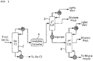
- FIG. 1 is a diagram illustrating a conventional process of preparing ethylene, and simply describing the process of preparing ethylene illustrated in FIG. 1 , first, when a hydrocarbon compound having two carbon atoms isolated from a De C2 column 2 is transferred to an acetylene converter 4, acetylene (C 2 H 2 ) of the hydrocarbon compound having two carbon atoms is converted into ethylene (C 2 H 4 ) or ethane (C 2 H 6 ).
- the present invention is directed to providing a method for preparing ethylene with improved energy efficiency, which can reduce the amount of a refrigerant used and thus reduce energy by installing a heat exchanger between columns used in preparation of ethylene to enable direct heat exchange between the columns.
- the present invention provides a method for preparing ethylene with improved energy efficiency, which includes: providing a C2 compound isolated from a de-ethanizer column to an acetylene converter to convert acetylene of the C2 compound into ethylene and ethane; transferring the C2 compound containing ethylene and ethane converted from acetylene to a first C2 splitter to isolate and discharge a part of the ethylene; and transferring a lower stream containing remaining ethylene and ethane, which are not discharged from the first C2 splitter, to a second C2 splitter, to isolate and discharge the ethylene, and converting the remaining C2 compound containing ethane into ethylene to be recycled.
- a heat exchanger is installed between the de-ethanizer column and the first C2 splitter to perform direct heat exchange between processes, a difference in pressure between the de-ethanizer column and the first C2 splitter to enable the heat exchange is 4.5 kgf/cm 2 G or more, and a concentration of ethylene contained in the lower stream of the first C2 splitter is 70 to 80 mol%.
- the amount of a refrigerant used can be reduced by installing a heat exchanger between columns used in preparation of ethylene to enable direct heat exchange between columns, resulting in energy savings due to the reduction of energy.
- FIG. 2 is a diagram of a process of preparing ethylene for illustrating a method for preparing ethylene with improved energy efficiency according to an exemplary embodiment of the present invention.
- the method for preparing ethylene with improved energy efficiency according to the present invention includes: providing a C2 compound isolated from a de-ethanizer column 10 to an acetylene converter 20 to convert acetylene (C 2 H 2 ) of the C2 compound into ethylene (C 2 H 4 ) and ethane (C 2 H 6 ); transferring the C2 compound containing ethylene and ethane converted from acetylene to a first C2 splitter 30 to isolate and discharge a part of the ethylene; and transferring a lower stream containing remaining ethylene and ethane, which are not discharged from the first C2 splitter 30, to a second C2 splitter 40, to isolate and discharge the ethylene, and converting the remaining C2 compound containing ethane into ethylene to be recycled.
- a heat exchanger 50 is installed between the de-ethanizer column 10 and the first C2 splitter 30 to perform direct heat exchange between processes, and a difference in pressure between the de-ethane column 10 and the first C2 splitter 30 to enable the heat exchange is 4.5 kgf/cm 2 G or more, and a concentration of ethylene contained in the lower stream of the first C2 splitter 30 is 70 to 80 mol%.
- the hydrocarbon compound having two carbon atoms isolated from the upper part of the de-ethanizer column 10 is transferred and provided to the acetylene converter 20, and acetylene of the hydrocarbon compound having two carbon atoms is converted into ethylene and ethane.
- the hydrocarbon compound having two carbon atoms containing the ethylene and the ethane converted from the acetylene is transferred to the first C2 splitter 30 and then a part of the ethylene is isolated and discharged.
- the lower stream of the first C2 splitter 30 containing remaining ethylene and ethane is transferred to the second C2 splitter 40 or provided to the heat exchanger 50, and after being transferred to the second C2 splitter 40, the ethylene is isolated and discharged, and the remaining hydrocarbon compound having two carbon atoms, which contains ethane, is recycled back to the preceding process (particularly, the ethane of the hydrocarbon compound having two carbon atoms is generally returned to an ethane cracker (not shown), and converted into ethylene, where the ethane cracker is a reactor in which a reaction of converting a byproduct produced in the second C2 splitter 40, that is, ethane into ethylene, and is generally included in an NCC process), and therefore, as the above-described process is performed, pure ethylene may be obtained.
- light impurities are discharged at the upper parts of the first C2 splitter 30 and the second C2 splitter 40, condensation caused by a refrigerant before discharging may be performed.
- the hydrocarbon compound discharged at the upper part of each of the de-ethanizer column 10, the first C2 splitter 30 and the second C2 splitter 40 is discharged in a vapor form, and condensed by a propylene refrigerant (or a propylene refrigerator; PR).
- a propylene refrigerant or a propylene refrigerator; PR.
- Each condensate obtained by condensation as described above is transferred to a subsequent stage or discharged to the outside, and some of the condensate is used as a heat source for each of the de-ethanizer column 10, the first C2 splitter 30 and the second C2 splitter 40.
- the propylene refrigerant (PR) is condensed and cooled in a PR loop, a PR compressor used in the compression of the refrigerant is operated by very high-pressure steam (XS), and after operating the PR compressor, a part of the PR produces high-pressure steam (HS), and the rest thereof is converted into a condensate.
- XS very high-pressure steam
- HS high-pressure steam
- the C2 compound transferred to acetylene converter 20 after being discharged at the upper part of the de-ethanizer column 10 is most of the hydrocarbon compound having two carbon atoms, and more particularly, refers to a hydrocarbon compound having two carbon atoms and a boiling point (bp) similar to ethylene.
- the present invention can achieve direct heat exchange between processes (or columns), that is, between the de-ethanizer column 10 and the first C2 splitter 30, due to the heat exchanger 50 between the de-ethanizer column 10 and the first C2 splitter 30.
- the direct heat exchange between the de-ethanizer column 10 and the first C2 splitter 30 is performed between the lower stream of the first C2 splitter 30 and the upper vapor (or upper stream) of the de-ethanizer column 10, and particularly, after the lower stream of the first C2 splitter 30 is provided to the heat exchanger 50, a part of the upper vapor of the de-ethanizer column 10 is condensed (the rest of the vapor is condensed by a refrigerant).
- this is different from a conventional case in which the lower stream of the first C2 splitter 30 is evaporated by heat provided from a vaporizer, and the upper vapor of the de-ethanizer column 10 is condensed only through heat recovery by a refrigerant.
- the amount of the propylene refrigerant used in the upper part of the de-ethanizer column 10 is reduced, leading to a reduction in the shaft work of the PR compressor compressing the refrigerant, and very high-pressure steam (XS) required for operation of the PR compressor may be reduced or the output of the high-pressure steam (HS) may be increased by reducing an amount of the condensate.
- XS very high-pressure steam
- HS high-pressure steam
- an heat exchange amount by the heat exchanger 50 varies according to two operation conditions, that is, a difference (P1 - P2) between a pressure (P1) of the de-ethanizer column 10 and a pressure (P2) of the first C2 splitter 30 and a concentration (mol%) of the ethylene contained in the lower stream of the first C2 splitter 30, and direct heat exchange between processes becomes possible when such operation conditions are optimized.
- the difference (P1 - P2) between a pressure (P1) of the de-ethanizer column 10 and a pressure (P2) of the first C2 splitter 30 is 4.5 kgf/cm 2 G or more, and preferably 4.5 to 15 kgf/cm 2 G, and when the difference in pressure between the de-ethanizer column 10 and the first C2 splitter 30 is less than 4.5 kgf/cm 2 G, it is impossible to ensure the minimum log mean temperature difference (LMTD) required for heat exchange, and thus the heat exchange itself may become impossible.
- LMTD log mean temperature difference
- the concentration of ethylene contained in the lower stream of the first C2 splitter is 70 to 80 mol%, and when the concentration of ethylene contained in the lower stream of the first C2 splitter 30 is less than 70 mol%, due to a decreased temperature of the ethylene input into the heat exchanger 50, the heat exchange becomes difficult, and when the concentration of ethylene contained in the lower stream of the first C2 splitter 30 is more than 80 mol%, the output of the ethylene of the first C2 splitter 30 is reduced, and thus the process of preparing ethylene becomes inefficient.
- a heat exchanger for direct heat exchange between processes was further installed between the de-ethanizer column and the first C2 splitter, and for optimal heat exchange, ethylene was prepared with the difference (P1 - P2) between the pressure (P1) of a de-ethanizer column and the pressure (p2) of a first C2 splitter of 4.5 kgf/cm 2 G, and a concentration of the ethylene in a lower stream of the first C2 splitter of 70 mol%.
- an amount of the final heat exchange, the shaft work of a PR loop used for condensing and cooling a refrigerant and a reduction amount thereof, an amount of very high-pressure steam (XS) used for operating a PR compressor used for compressing a refrigerant, an amount of high-pressure steam (HS) produced after operating the PR compressor, and an amount of high-pressure steam (HS) converted at the same time as a reduction in the amount of condensate obtained by the operation of the PR compressor are shown in Table 1.
- Example 1 Example 2 Comparative Example 1 Comparative Example 2 P1 (kgf/cm 2 G) 27.3 27.3 27.3 27.3 P2 (kgf/cm 2 G) 22.8 22.7 22.3 23.3 P1 - P2 (kgf/cm 2 G) 4.5 4.6 5.0 4.0 Concentration of ethylene in lower stream of first C2 splitter (mol%) 70.00 78.80 60.00 60.00 Heat exchange amount (Q HX, Gcal/hr) 0.035 3.0 0 0 Shaft work of PR loop (kW) 28314.6 27436.0 28325.0 28325.0 Shaft work reduction amount of PR loop (kW) 10.4 889.0 0 0 XS input (ton/hr) 343.87 343.87 343.87 HS output (ton/hr) 289.43 293.58 289.38 289.38 HS additional output (ton/hr) 0.05 4.20 0 0 0
- Ethylene was prepared in the same manner as described in Example 1, except that the difference (P1 - P2) between the pressure (P1) of the de-ethanizer column and the pressure (P2) of the first C2 splitter was 4.6 kgf/cm 2 G, and the concentration of the ethylene in the lower stream of the first C2 splitter was 78.80 mol%.
- an amount of the final heat exchange, the shaft work of a PR loop used for condensing and cooling a refrigerant and a reduction amount thereof, an amount of very high-pressure steam (XS) used for operating a PR compressor used for compressing a refrigerant, an amount of high-pressure steam (HS) produced after operating the PR compressor, and an amount of high-pressure steam (HS) converted at the same time as a reduction in the amount of condensate obtained by the operation of the PR compressor are shown in Table 1.
- Ethylene was prepared in the same manner as described in Example 1, except that the difference (P1 - P2) between the pressure (P1) of the de-ethanizer column and the pressure (P2) of the first C2 splitter was 5.0 kgf/cm 2 G, and the concentration of the ethylene in the lower stream of the first C2 splitter was 60.00 mol%.
- an amount of the final heat exchange, the shaft work of a PR loop used for condensing and cooling a refrigerant and a reduction amount thereof, an amount of very high-pressure steam (XS) used for operating a PR compressor used for compressing a refrigerant, an amount of high-pressure steam (HS) produced after operating the PR compressor, and an amount of high-pressure steam (HS) converted at the same time as a reduction in the amount of condensate obtained by the operation of the PR compressor are shown in Table 1.
- Ethylene was prepared in the same manner as described in Example 1, except that the difference (P1 - P2) between the pressure (P1) of the de-ethanizer column and the pressure (P2) of the first C2 splitter was 4.0 kgf/cm 2 G, and the concentration of the ethylene in the lower stream of the first C2 splitter was 60.00 mol%.
- an amount of the final heat exchange, the shaft work of a PR loop used for condensing and cooling a refrigerant and a reduction amount thereof, an amount of very high-pressure steam (XS) used for operating a PR compressor used for compressing a refrigerant, an amount of high-pressure steam (HS) produced after operating the PR compressor, and an amount of high-pressure steam (HS) converted at the same time as a reduction in the amount of condensate obtained by the operation of the PR compressor are shown in Table 1.
Landscapes
- Chemical & Material Sciences (AREA)
- Organic Chemistry (AREA)
- Engineering & Computer Science (AREA)
- Oil, Petroleum & Natural Gas (AREA)
- Analytical Chemistry (AREA)
- Water Supply & Treatment (AREA)
- Chemical Kinetics & Catalysis (AREA)
- General Chemical & Material Sciences (AREA)
- Organic Low-Molecular-Weight Compounds And Preparation Thereof (AREA)
Abstract
Description
- This application claims the benefit of Korean Patent Application No.
10-2016-0056943, filed on May 10, 2016 - The present invention relates to a method for preparing ethylene with improved energy efficiency, and more preferably, to a method for preparing ethylene with improved energy efficiency, which can reduce energy due to direct thermal exchange between processes.
- Usually, in preparation of ethylene, various methods such as ethane cracking, petroleum degradation, combustion, acetylene hydrogenation and alcohol dehydration have been used.
FIG. 1 is a diagram illustrating a conventional process of preparing ethylene, and simply describing the process of preparing ethylene illustrated inFIG. 1 , first, when a hydrocarbon compound having two carbon atoms isolated from a De C2 column 2 is transferred to anacetylene converter 4, acetylene (C2H2) of the hydrocarbon compound having two carbon atoms is converted into ethylene (C2H4) or ethane (C2H6). Subsequently, after ethylene and ethane are transferred to a first C2S column 6, a part of the ethylene is isolated first, remaining ethylene and ethane are transferred to asecond C2S column 8, followed by isolating and discharging ethylene, and ethane is recycled back to the preceding process, resulting in the obtainment of pure ethylene. - In the above-mentioned process for preparing ethylene, a refrigerant loop is connected with each column, an energy source such as high-pressure steam is necessary to operate the refrigerant loop. However, in this case, since there is a problem such as a malfunction due to an increased load applied to the refrigerant loop, it is necessary to conduct studies on a method for reducing a load applied to a refrigerant loop by reducing an energy source provided to the refrigerant loop.
- Therefore, the present invention is directed to providing a method for preparing ethylene with improved energy efficiency, which can reduce the amount of a refrigerant used and thus reduce energy by installing a heat exchanger between columns used in preparation of ethylene to enable direct heat exchange between the columns.
- To achieve the purpose, the present invention provides a method for preparing ethylene with improved energy efficiency, which includes: providing a C2 compound isolated from a de-ethanizer column to an acetylene converter to convert acetylene of the C2 compound into ethylene and ethane; transferring the C2 compound containing ethylene and ethane converted from acetylene to a first C2 splitter to isolate and discharge a part of the ethylene; and transferring a lower stream containing remaining ethylene and ethane, which are not discharged from the first C2 splitter, to a second C2 splitter, to isolate and discharge the ethylene, and converting the remaining C2 compound containing ethane into ethylene to be recycled. Here, a heat exchanger is installed between the de-ethanizer column and the first C2 splitter to perform direct heat exchange between processes, a difference in pressure between the de-ethanizer column and the first C2 splitter to enable the heat exchange is 4.5 kgf/cm2 G or more, and a concentration of ethylene contained in the lower stream of the first C2 splitter is 70 to 80 mol%.
- In a method for preparing ethylene with improved energy efficiency according to the present invention, the amount of a refrigerant used can be reduced by installing a heat exchanger between columns used in preparation of ethylene to enable direct heat exchange between columns, resulting in energy savings due to the reduction of energy.
-
-
FIG. 1 is a diagram illustrating a conventional process of preparing ethylene. -
FIG. 2 is a diagram of a process of preparing ethylene for illustrating a method for preparing ethylene with improved energy efficiency according to an exemplary embodiment of the present invention. -
- 10: De-ethanizer column
- 20: Acetylene converter
- 30: First C2 splitter
- 40: Second C2 splitter
- 50: Heat exchanger
- Hereinafter, the present invention will be described in detail with reference to the accompanying drawings.
-
FIG. 2 is a diagram of a process of preparing ethylene for illustrating a method for preparing ethylene with improved energy efficiency according to an exemplary embodiment of the present invention. Referring toFIG. 2 , the method for preparing ethylene with improved energy efficiency according to the present invention includes: providing a C2 compound isolated from ade-ethanizer column 10 to anacetylene converter 20 to convert acetylene (C2H2) of the C2 compound into ethylene (C2H4) and ethane (C2H6); transferring the C2 compound containing ethylene and ethane converted from acetylene to afirst C2 splitter 30 to isolate and discharge a part of the ethylene; and transferring a lower stream containing remaining ethylene and ethane, which are not discharged from thefirst C2 splitter 30, to asecond C2 splitter 40, to isolate and discharge the ethylene, and converting the remaining C2 compound containing ethane into ethylene to be recycled. - A
heat exchanger 50 is installed between thede-ethanizer column 10 and thefirst C2 splitter 30 to perform direct heat exchange between processes, and a difference in pressure between thede-ethane column 10 and thefirst C2 splitter 30 to enable the heat exchange is 4.5 kgf/cm2 G or more, and a concentration of ethylene contained in the lower stream of thefirst C2 splitter 30 is 70 to 80 mol%. - Describing the method for preparing ethylene with improved energy efficiency in further detail, first, when a hydrocarbon compound having two or more carbon atoms from a de-methanizer column (not shown) is provided to the
de-ethanizer column 10, the hydrocarbon compound having two carbon atoms is isolated and transferred to a subsequent stage via the upper part of thede-ethanizer column 10, and a hydrocarbon compound having three or more carbon atoms is transferred to a de-propanizer column (not shown) via the lower part of the de-ethanizercolumn 10. Subsequently, the hydrocarbon compound having two carbon atoms isolated from the upper part of thede-ethanizer column 10 is transferred and provided to theacetylene converter 20, and acetylene of the hydrocarbon compound having two carbon atoms is converted into ethylene and ethane. Subsequently, the hydrocarbon compound having two carbon atoms containing the ethylene and the ethane converted from the acetylene is transferred to thefirst C2 splitter 30 and then a part of the ethylene is isolated and discharged. The lower stream of thefirst C2 splitter 30 containing remaining ethylene and ethane is transferred to thesecond C2 splitter 40 or provided to theheat exchanger 50, and after being transferred to thesecond C2 splitter 40, the ethylene is isolated and discharged, and the remaining hydrocarbon compound having two carbon atoms, which contains ethane, is recycled back to the preceding process (particularly, the ethane of the hydrocarbon compound having two carbon atoms is generally returned to an ethane cracker (not shown), and converted into ethylene, where the ethane cracker is a reactor in which a reaction of converting a byproduct produced in thesecond C2 splitter 40, that is, ethane into ethylene, and is generally included in an NCC process), and therefore, as the above-described process is performed, pure ethylene may be obtained. In addition, light impurities are discharged at the upper parts of thefirst C2 splitter 30 and thesecond C2 splitter 40, condensation caused by a refrigerant before discharging may be performed. - Meanwhile, the hydrocarbon compound discharged at the upper part of each of the
de-ethanizer column 10, thefirst C2 splitter 30 and thesecond C2 splitter 40 is discharged in a vapor form, and condensed by a propylene refrigerant (or a propylene refrigerator; PR). Each condensate obtained by condensation as described above is transferred to a subsequent stage or discharged to the outside, and some of the condensate is used as a heat source for each of thede-ethanizer column 10, thefirst C2 splitter 30 and thesecond C2 splitter 40. In addition, the propylene refrigerant (PR) is condensed and cooled in a PR loop, a PR compressor used in the compression of the refrigerant is operated by very high-pressure steam (XS), and after operating the PR compressor, a part of the PR produces high-pressure steam (HS), and the rest thereof is converted into a condensate. - Meanwhile, the C2 compound transferred to
acetylene converter 20 after being discharged at the upper part of thede-ethanizer column 10 is most of the hydrocarbon compound having two carbon atoms, and more particularly, refers to a hydrocarbon compound having two carbon atoms and a boiling point (bp) similar to ethylene. - As described in
FIG. 2 , the present invention can achieve direct heat exchange between processes (or columns), that is, between thede-ethanizer column 10 and thefirst C2 splitter 30, due to theheat exchanger 50 between thede-ethanizer column 10 and thefirst C2 splitter 30. Here, the direct heat exchange between the de-ethanizercolumn 10 and thefirst C2 splitter 30 is performed between the lower stream of thefirst C2 splitter 30 and the upper vapor (or upper stream) of the de-ethanizercolumn 10, and particularly, after the lower stream of thefirst C2 splitter 30 is provided to theheat exchanger 50, a part of the upper vapor of thede-ethanizer column 10 is condensed (the rest of the vapor is condensed by a refrigerant). That is, this is different from a conventional case in which the lower stream of thefirst C2 splitter 30 is evaporated by heat provided from a vaporizer, and the upper vapor of the de-ethanizercolumn 10 is condensed only through heat recovery by a refrigerant. - That is, as described above, when the direct heat exchange between the
de-ethanizer column 10 andfirst C2 splitter 30 is performed, the amount of the propylene refrigerant used in the upper part of the de-ethanizercolumn 10 is reduced, leading to a reduction in the shaft work of the PR compressor compressing the refrigerant, and very high-pressure steam (XS) required for operation of the PR compressor may be reduced or the output of the high-pressure steam (HS) may be increased by reducing an amount of the condensate. - Meanwhile, an heat exchange amount by the
heat exchanger 50 varies according to two operation conditions, that is, a difference (P1 - P2) between a pressure (P1) of thede-ethanizer column 10 and a pressure (P2) of thefirst C2 splitter 30 and a concentration (mol%) of the ethylene contained in the lower stream of thefirst C2 splitter 30, and direct heat exchange between processes becomes possible when such operation conditions are optimized. - The difference (P1 - P2) between a pressure (P1) of the de-ethanizer
column 10 and a pressure (P2) of thefirst C2 splitter 30 is 4.5 kgf/cm2 G or more, and preferably 4.5 to 15 kgf/cm2 G, and when the difference in pressure between thede-ethanizer column 10 and thefirst C2 splitter 30 is less than 4.5 kgf/cm2 G, it is impossible to ensure the minimum log mean temperature difference (LMTD) required for heat exchange, and thus the heat exchange itself may become impossible. - In addition, the concentration of ethylene contained in the lower stream of the first C2 splitter is 70 to 80 mol%, and when the concentration of ethylene contained in the lower stream of the
first C2 splitter 30 is less than 70 mol%, due to a decreased temperature of the ethylene input into theheat exchanger 50, the heat exchange becomes difficult, and when the concentration of ethylene contained in the lower stream of thefirst C2 splitter 30 is more than 80 mol%, the output of the ethylene of thefirst C2 splitter 30 is reduced, and thus the process of preparing ethylene becomes inefficient. - Hereinafter, exemplary examples will be provided to help in understanding of the present invention. However, it is apparent to those of ordinary skill in the art that the above descriptions of the present invention are exemplary, and the exemplary embodiments disclosed herein can be easily modified into other specific forms without changing the technical spirit or essential features of the present invention, and such variations and modifications should be within the scope of the appended claims.
- In addition to the conventional de-ethanizer column, acetylene converter, first C2 splitter and second C2 splitter for preparing ethylene, a heat exchanger for direct heat exchange between processes was further installed between the de-ethanizer column and the first C2 splitter, and for optimal heat exchange, ethylene was prepared with the difference (P1 - P2) between the pressure (P1) of a de-ethanizer column and the pressure (p2) of a first C2 splitter of 4.5 kgf/cm2 G, and a concentration of the ethylene in a lower stream of the first C2 splitter of 70 mol%. In the preparation of ethylene, an amount of the final heat exchange, the shaft work of a PR loop used for condensing and cooling a refrigerant and a reduction amount thereof, an amount of very high-pressure steam (XS) used for operating a PR compressor used for compressing a refrigerant, an amount of high-pressure steam (HS) produced after operating the PR compressor, and an amount of high-pressure steam (HS) converted at the same time as a reduction in the amount of condensate obtained by the operation of the PR compressor are shown in Table 1.
[Table 1] Example 1 Example 2 Comparative Example 1 Comparative Example 2 P1 (kgf/cm2 G) 27.3 27.3 27.3 27.3 P2 (kgf/cm2 G) 22.8 22.7 22.3 23.3 P1 - P2 (kgf/cm2 G) 4.5 4.6 5.0 4.0 Concentration of ethylene in lower stream of first C2 splitter (mol%) 70.00 78.80 60.00 60.00 Heat exchange amount (Q HX, Gcal/hr) 0.035 3.0 0 0 Shaft work of PR loop (kW) 28314.6 27436.0 28325.0 28325.0 Shaft work reduction amount of PR loop (kW) 10.4 889.0 0 0 XS input (ton/hr) 343.87 343.87 343.87 343.87 HS output (ton/hr) 289.43 293.58 289.38 289.38 HS additional output (ton/hr) 0.05 4.20 0 0 - Ethylene was prepared in the same manner as described in Example 1, except that the difference (P1 - P2) between the pressure (P1) of the de-ethanizer column and the pressure (P2) of the first C2 splitter was 4.6 kgf/cm2 G, and the concentration of the ethylene in the lower stream of the first C2 splitter was 78.80 mol%. In the preparation of ethylene, an amount of the final heat exchange, the shaft work of a PR loop used for condensing and cooling a refrigerant and a reduction amount thereof, an amount of very high-pressure steam (XS) used for operating a PR compressor used for compressing a refrigerant, an amount of high-pressure steam (HS) produced after operating the PR compressor, and an amount of high-pressure steam (HS) converted at the same time as a reduction in the amount of condensate obtained by the operation of the PR compressor are shown in Table 1.
- Ethylene was prepared in the same manner as described in Example 1, except that the difference (P1 - P2) between the pressure (P1) of the de-ethanizer column and the pressure (P2) of the first C2 splitter was 5.0 kgf/cm2 G, and the concentration of the ethylene in the lower stream of the first C2 splitter was 60.00 mol%. In the preparation of ethylene, an amount of the final heat exchange, the shaft work of a PR loop used for condensing and cooling a refrigerant and a reduction amount thereof, an amount of very high-pressure steam (XS) used for operating a PR compressor used for compressing a refrigerant, an amount of high-pressure steam (HS) produced after operating the PR compressor, and an amount of high-pressure steam (HS) converted at the same time as a reduction in the amount of condensate obtained by the operation of the PR compressor are shown in Table 1.
- Ethylene was prepared in the same manner as described in Example 1, except that the difference (P1 - P2) between the pressure (P1) of the de-ethanizer column and the pressure (P2) of the first C2 splitter was 4.0 kgf/cm2 G, and the concentration of the ethylene in the lower stream of the first C2 splitter was 60.00 mol%. In the preparation of ethylene, an amount of the final heat exchange, the shaft work of a PR loop used for condensing and cooling a refrigerant and a reduction amount thereof, an amount of very high-pressure steam (XS) used for operating a PR compressor used for compressing a refrigerant, an amount of high-pressure steam (HS) produced after operating the PR compressor, and an amount of high-pressure steam (HS) converted at the same time as a reduction in the amount of condensate obtained by the operation of the PR compressor are shown in Table 1.
- As shown in Table 1, in Examples 1 and 2 in which two operation conditions are optimized, in other words, the difference (P1 - P2) between the pressure (P1) of the de-ethanizer column and the pressure (P2) of the first C2 splitter was set to 4.5 kgf/cm2 G or more, and the concentration of the ethylene in the lower stream of the first C2 splitter was set to 70 to 80 mol%, heat exchange was able to be performed (heat exchange amount: Example 1 - 0.035 Gcal/hr, Example 2 - 3.0 Gcal/hr), resulting in the reduction of the use of a refrigerant, which can be confirmed by the facts that the shaft work required for the PR compressor used for condensing and cooling a refrigerant was reduced (shaft work reduction amount of the PR compressor: Example 1 - 10.4 kW, Example 2 - 889 kW), and that the high-pressure steam (HS) was additionally produced by converting the condensate into the high-pressure steam (HS) at the same time as an amount of the condensate converted by the driving of the PR compressor used in compression of the refrigerant was decreased (HS additional output: Example 1 - 0.05 ton/hr, Example 2 - 4.2 ton/hr).
- Meanwhile, in Comparative Example 1 satisfying only one (the difference between the pressure of the de-ethanizer column and the pressure of the first C2 splitter) of the two operation conditions, it was confirmed that, like Comparative Example 2 that did not satisfy neither of the two operation conditions, heat exchange cannot be performed, and therefore, it can be seen that, according to the method for preparing ethylene with improved energy efficiency according to the present invention, both of the difference between the pressure of the de-ethanizer column and the pressure of the first C2 splitter and the concentration of the ethylene in the lower stream of the first C2 splitter should be optimized.
Claims (7)
- A method for preparing ethylene with improved energy efficiency, comprising:providing a C2 compound isolated from a de-ethanizer column to an acetylene converter to convert acetylene of the C2 compound into ethylene and ethane;transferring the C2 compound containing ethylene and ethane converted from acetylene to a first C2 splitter to isolate and discharge a part of the ethylene; andtransferring a lower stream containing remaining ethylene and ethane, which are not discharged from the first C2 splitter, to a second C2 splitter, to isolate and discharge the ethylene, and converting the remaining C2 compound containing ethane into ethylene to be recycled,wherein a heat exchanger is installed between the de-ethanizer column and the first C2 splitter to perform direct heat exchange between processes, a difference in pressure between the de-ethanizer column and the first C2 splitter to enable the heat exchange is 4.5 kgf/cm2 G or more, and a concentration of ethylene contained in the lower stream of the first C2 splitter is 70 to 80 mol%.
- The method of claim 1, wherein a heat exchange amount obtained by the heat exchanger varies according to a difference (P1 - P2) between a pressure of the de-ethanizer column (P1) and a pressure (P2) of the first C2 splitter and a concentration (mol%) of the ethylene contained in the lower stream of the first C2 splitter.
- The method of claim 1, wherein the difference between the pressure of the de-ethanizer column and the pressure of the first C2 splitter is 4.5 to 15 kgf/cm2 G.
- The method of claim 1, wherein the lower stream of the first C2 splitter is transferred to the second C2 splitter or provided to the heat exchanger.
- The method of claim 1, wherein the heat exchange is performed between the lower stream of the first C2 splitter and an upper vapor of the de-ethanizer column.
- The method of claim 1, wherein the lower stream of the first C2 splitter allows a part of the upper vapor of the de-ethanizer column to be condensed after being provided to the heat exchanger.
- The method of claim 1, wherein, when the heat exchange is performed between the de-ethanizer column and the first C2 splitter, an amount of a refrigerant used in the upper part of the de-ethanizer column is decreased.
Applications Claiming Priority (2)
| Application Number | Priority Date | Filing Date | Title |
|---|---|---|---|
| KR1020160056943A KR102071591B1 (en) | 2016-05-10 | 2016-05-10 | Method for preparing of ethylene improved an energy efficiency |
| PCT/KR2017/003794 WO2017195989A1 (en) | 2016-05-10 | 2017-04-07 | Ethylene preparation method having improved energy efficiency |
Publications (3)
| Publication Number | Publication Date |
|---|---|
| EP3345887A1 true EP3345887A1 (en) | 2018-07-11 |
| EP3345887A4 EP3345887A4 (en) | 2018-11-07 |
| EP3345887B1 EP3345887B1 (en) | 2020-08-12 |
Family
ID=60267294
Family Applications (1)
| Application Number | Title | Priority Date | Filing Date |
|---|---|---|---|
| EP17796289.1A Active EP3345887B1 (en) | 2016-05-10 | 2017-04-07 | Ethylene preparation method having improved energy efficiency |
Country Status (6)
| Country | Link |
|---|---|
| US (1) | US10294177B2 (en) |
| EP (1) | EP3345887B1 (en) |
| JP (1) | JP6651622B2 (en) |
| KR (1) | KR102071591B1 (en) |
| CN (1) | CN108349849B (en) |
| WO (1) | WO2017195989A1 (en) |
Cited By (1)
| Publication number | Priority date | Publication date | Assignee | Title |
|---|---|---|---|---|
| EP3666855A4 (en) * | 2018-09-04 | 2020-11-11 | LG Chem, Ltd. | PROCESS FOR PRODUCING ETHYLENE |
Families Citing this family (3)
| Publication number | Priority date | Publication date | Assignee | Title |
|---|---|---|---|---|
| WO2020050487A1 (en) * | 2018-09-04 | 2020-03-12 | 주식회사 엘지화학 | Ethylene manufacturing method and ethylene manufacturing device |
| KR102423688B1 (en) | 2018-09-04 | 2022-07-21 | 주식회사 엘지화학 | Method for preparing ethylene and apparatus for preparing ethylene |
| KR102755274B1 (en) | 2024-07-05 | 2025-01-22 | 최병렬 | High-efficiency Compressor-Reactor Catalyst based ethylene, propane and polymer production system and its operation method |
Family Cites Families (9)
| Publication number | Priority date | Publication date | Assignee | Title |
|---|---|---|---|---|
| FR2458525A1 (en) * | 1979-06-06 | 1981-01-02 | Technip Cie | IMPROVED PROCESS FOR THE PRODUCTION OF ETHYLENE AND ETHYLENE PRODUCTION PLANT COMPRISING THE APPLICATION OF SAID METHOD |
| US5326929A (en) | 1992-02-19 | 1994-07-05 | Advanced Extraction Technologies, Inc. | Absorption process for hydrogen and ethylene recovery |
| US5220097A (en) | 1992-02-19 | 1993-06-15 | Advanced Extraction Technologies, Inc. | Front-end hydrogenation and absorption process for ethylene recovery |
| US7294749B2 (en) | 2004-07-02 | 2007-11-13 | Kellogg Brown & Root Llc | Low pressure olefin recovery process |
| US7207192B2 (en) | 2004-07-28 | 2007-04-24 | Kellogg Brown & Root Llc | Secondary deethanizer to debottleneck an ethylene plant |
| US7437891B2 (en) * | 2004-12-20 | 2008-10-21 | Ineos Usa Llc | Recovery and purification of ethylene |
| US9103586B2 (en) * | 2006-12-16 | 2015-08-11 | Kellogg Brown & Root Llc | Advanced C2-splitter feed rectifier |
| US7842847B2 (en) | 2008-06-27 | 2010-11-30 | Lummus Technology Inc. | Separation process for olefin production |
| CN102746083B (en) * | 2011-04-22 | 2014-08-13 | 中国石油化工股份有限公司 | Technology for separating low carbon olefin gases |
-
2016
- 2016-05-10 KR KR1020160056943A patent/KR102071591B1/en active Active
-
2017
- 2017-04-07 US US15/762,426 patent/US10294177B2/en active Active
- 2017-04-07 WO PCT/KR2017/003794 patent/WO2017195989A1/en not_active Ceased
- 2017-04-07 CN CN201780003771.8A patent/CN108349849B/en active Active
- 2017-04-07 EP EP17796289.1A patent/EP3345887B1/en active Active
- 2017-04-07 JP JP2018523002A patent/JP6651622B2/en active Active
Cited By (2)
| Publication number | Priority date | Publication date | Assignee | Title |
|---|---|---|---|---|
| EP3666855A4 (en) * | 2018-09-04 | 2020-11-11 | LG Chem, Ltd. | PROCESS FOR PRODUCING ETHYLENE |
| US11485692B2 (en) | 2018-09-04 | 2022-11-01 | Lg Chem, Ltd. | Method for preparing ethylene |
Also Published As
| Publication number | Publication date |
|---|---|
| CN108349849B (en) | 2021-02-12 |
| WO2017195989A1 (en) | 2017-11-16 |
| US20190152879A9 (en) | 2019-05-23 |
| KR102071591B1 (en) | 2020-01-30 |
| JP6651622B2 (en) | 2020-02-19 |
| KR20170126650A (en) | 2017-11-20 |
| US20180297915A1 (en) | 2018-10-18 |
| US10294177B2 (en) | 2019-05-21 |
| CN108349849A (en) | 2018-07-31 |
| JP2018537439A (en) | 2018-12-20 |
| EP3345887A4 (en) | 2018-11-07 |
| EP3345887B1 (en) | 2020-08-12 |
Similar Documents
| Publication | Publication Date | Title |
|---|---|---|
| EP3345887B1 (en) | Ethylene preparation method having improved energy efficiency | |
| KR101940352B1 (en) | Low-energy consumption method for dehydrating ethanol into ethylene | |
| AU2012367104B2 (en) | Process and plant for distillation of methanol with heat recuperation | |
| KR101753567B1 (en) | High energy reduction in a propane dehydrogenation unit by utilizing a high pressure product splitter column | |
| KR102152079B1 (en) | Integrated propane dehydrogenation process | |
| US7157610B2 (en) | Process for recovering methanol | |
| MX2014008832A (en) | Process and plant for distillation of methanol with heat recovery. | |
| US20190152878A1 (en) | Method of separating normal butene using isomerization and process system for separating normal butene | |
| KR102308606B1 (en) | Process for purification of a mixture of components having similar boiling points | |
| US11401221B2 (en) | Method for producing a stream of propylene and associated facility | |
| EP4394018A1 (en) | Novel process of absorption and stabilization unit and comprehensive utilization method of products therefrom | |
| TWI458538B (en) | System and process for producing linear alpha olefins | |
| CN120698842B (en) | A method for preparing benzene from cyclohexane with high efficiency and low energy consumption | |
| CN114917608B (en) | A low-energy propylene oligomer separation system and separation method | |
| TW201414530A (en) | Separation process and superfractionation system | |
| CN110937970A (en) | Method and system for preparing propylene | |
| CN118526810A (en) | Energy-saving propane dehydrogenation system and method | |
| KR20250071836A (en) | Method for purifying isopropyl alcohol | |
| WO2026033194A1 (en) | Process for separating vinyl chloride monomer from incondensables | |
| CN121801599A (en) | A system and method for reducing ethylene loss in light pyrolysis feedstocks | |
| CN108623426A (en) | A kind of low power technology and device recycling alkene from epoxidation product |
Legal Events
| Date | Code | Title | Description |
|---|---|---|---|
| STAA | Information on the status of an ep patent application or granted ep patent |
Free format text: STATUS: THE INTERNATIONAL PUBLICATION HAS BEEN MADE |
|
| PUAI | Public reference made under article 153(3) epc to a published international application that has entered the european phase |
Free format text: ORIGINAL CODE: 0009012 |
|
| STAA | Information on the status of an ep patent application or granted ep patent |
Free format text: STATUS: REQUEST FOR EXAMINATION WAS MADE |
|
| 17P | Request for examination filed |
Effective date: 20180315 |
|
| AK | Designated contracting states |
Kind code of ref document: A1 Designated state(s): AL AT BE BG CH CY CZ DE DK EE ES FI FR GB GR HR HU IE IS IT LI LT LU LV MC MK MT NL NO PL PT RO RS SE SI SK SM TR |
|
| AX | Request for extension of the european patent |
Extension state: BA ME |
|
| A4 | Supplementary search report drawn up and despatched |
Effective date: 20181005 |
|
| RIC1 | Information provided on ipc code assigned before grant |
Ipc: C07C 11/24 20060101ALI20180929BHEP Ipc: C07C 7/04 20060101AFI20180929BHEP Ipc: C07C 11/04 20060101ALI20180929BHEP Ipc: C07C 9/06 20060101ALI20180929BHEP |
|
| STAA | Information on the status of an ep patent application or granted ep patent |
Free format text: STATUS: EXAMINATION IS IN PROGRESS |
|
| 17Q | First examination report despatched |
Effective date: 20190226 |
|
| DAV | Request for validation of the european patent (deleted) | ||
| DAX | Request for extension of the european patent (deleted) | ||
| GRAP | Despatch of communication of intention to grant a patent |
Free format text: ORIGINAL CODE: EPIDOSNIGR1 |
|
| STAA | Information on the status of an ep patent application or granted ep patent |
Free format text: STATUS: GRANT OF PATENT IS INTENDED |
|
| INTG | Intention to grant announced |
Effective date: 20200602 |
|
| GRAS | Grant fee paid |
Free format text: ORIGINAL CODE: EPIDOSNIGR3 |
|
| GRAA | (expected) grant |
Free format text: ORIGINAL CODE: 0009210 |
|
| STAA | Information on the status of an ep patent application or granted ep patent |
Free format text: STATUS: THE PATENT HAS BEEN GRANTED |
|
| AK | Designated contracting states |
Kind code of ref document: B1 Designated state(s): AL AT BE BG CH CY CZ DE DK EE ES FI FR GB GR HR HU IE IS IT LI LT LU LV MC MK MT NL NO PL PT RO RS SE SI SK SM TR |
|
| REG | Reference to a national code |
Ref country code: CH Ref legal event code: EP |
|
| REG | Reference to a national code |
Ref country code: IE Ref legal event code: FG4D |
|
| REG | Reference to a national code |
Ref country code: DE Ref legal event code: R096 Ref document number: 602017021663 Country of ref document: DE |
|
| REG | Reference to a national code |
Ref country code: AT Ref legal event code: REF Ref document number: 1301418 Country of ref document: AT Kind code of ref document: T Effective date: 20200915 |
|
| REG | Reference to a national code |
Ref country code: LT Ref legal event code: MG4D |
|
| REG | Reference to a national code |
Ref country code: NL Ref legal event code: MP Effective date: 20200812 |
|
| PG25 | Lapsed in a contracting state [announced via postgrant information from national office to epo] |
Ref country code: HR Free format text: LAPSE BECAUSE OF FAILURE TO SUBMIT A TRANSLATION OF THE DESCRIPTION OR TO PAY THE FEE WITHIN THE PRESCRIBED TIME-LIMIT Effective date: 20200812 Ref country code: LT Free format text: LAPSE BECAUSE OF FAILURE TO SUBMIT A TRANSLATION OF THE DESCRIPTION OR TO PAY THE FEE WITHIN THE PRESCRIBED TIME-LIMIT Effective date: 20200812 Ref country code: BG Free format text: LAPSE BECAUSE OF FAILURE TO SUBMIT A TRANSLATION OF THE DESCRIPTION OR TO PAY THE FEE WITHIN THE PRESCRIBED TIME-LIMIT Effective date: 20201112 Ref country code: SE Free format text: LAPSE BECAUSE OF FAILURE TO SUBMIT A TRANSLATION OF THE DESCRIPTION OR TO PAY THE FEE WITHIN THE PRESCRIBED TIME-LIMIT Effective date: 20200812 Ref country code: GR Free format text: LAPSE BECAUSE OF FAILURE TO SUBMIT A TRANSLATION OF THE DESCRIPTION OR TO PAY THE FEE WITHIN THE PRESCRIBED TIME-LIMIT Effective date: 20201113 Ref country code: FI Free format text: LAPSE BECAUSE OF FAILURE TO SUBMIT A TRANSLATION OF THE DESCRIPTION OR TO PAY THE FEE WITHIN THE PRESCRIBED TIME-LIMIT Effective date: 20200812 Ref country code: NO Free format text: LAPSE BECAUSE OF FAILURE TO SUBMIT A TRANSLATION OF THE DESCRIPTION OR TO PAY THE FEE WITHIN THE PRESCRIBED TIME-LIMIT Effective date: 20201112 |
|
| REG | Reference to a national code |
Ref country code: AT Ref legal event code: MK05 Ref document number: 1301418 Country of ref document: AT Kind code of ref document: T Effective date: 20200812 |
|
| PG25 | Lapsed in a contracting state [announced via postgrant information from national office to epo] |
Ref country code: NL Free format text: LAPSE BECAUSE OF FAILURE TO SUBMIT A TRANSLATION OF THE DESCRIPTION OR TO PAY THE FEE WITHIN THE PRESCRIBED TIME-LIMIT Effective date: 20200812 Ref country code: LV Free format text: LAPSE BECAUSE OF FAILURE TO SUBMIT A TRANSLATION OF THE DESCRIPTION OR TO PAY THE FEE WITHIN THE PRESCRIBED TIME-LIMIT Effective date: 20200812 Ref country code: RS Free format text: LAPSE BECAUSE OF FAILURE TO SUBMIT A TRANSLATION OF THE DESCRIPTION OR TO PAY THE FEE WITHIN THE PRESCRIBED TIME-LIMIT Effective date: 20200812 Ref country code: PL Free format text: LAPSE BECAUSE OF FAILURE TO SUBMIT A TRANSLATION OF THE DESCRIPTION OR TO PAY THE FEE WITHIN THE PRESCRIBED TIME-LIMIT Effective date: 20200812 Ref country code: IS Free format text: LAPSE BECAUSE OF FAILURE TO SUBMIT A TRANSLATION OF THE DESCRIPTION OR TO PAY THE FEE WITHIN THE PRESCRIBED TIME-LIMIT Effective date: 20201212 |
|
| PG25 | Lapsed in a contracting state [announced via postgrant information from national office to epo] |
Ref country code: CZ Free format text: LAPSE BECAUSE OF FAILURE TO SUBMIT A TRANSLATION OF THE DESCRIPTION OR TO PAY THE FEE WITHIN THE PRESCRIBED TIME-LIMIT Effective date: 20200812 Ref country code: DK Free format text: LAPSE BECAUSE OF FAILURE TO SUBMIT A TRANSLATION OF THE DESCRIPTION OR TO PAY THE FEE WITHIN THE PRESCRIBED TIME-LIMIT Effective date: 20200812 Ref country code: RO Free format text: LAPSE BECAUSE OF FAILURE TO SUBMIT A TRANSLATION OF THE DESCRIPTION OR TO PAY THE FEE WITHIN THE PRESCRIBED TIME-LIMIT Effective date: 20200812 Ref country code: EE Free format text: LAPSE BECAUSE OF FAILURE TO SUBMIT A TRANSLATION OF THE DESCRIPTION OR TO PAY THE FEE WITHIN THE PRESCRIBED TIME-LIMIT Effective date: 20200812 Ref country code: SM Free format text: LAPSE BECAUSE OF FAILURE TO SUBMIT A TRANSLATION OF THE DESCRIPTION OR TO PAY THE FEE WITHIN THE PRESCRIBED TIME-LIMIT Effective date: 20200812 |
|
| REG | Reference to a national code |
Ref country code: DE Ref legal event code: R097 Ref document number: 602017021663 Country of ref document: DE |
|
| PG25 | Lapsed in a contracting state [announced via postgrant information from national office to epo] |
Ref country code: AL Free format text: LAPSE BECAUSE OF FAILURE TO SUBMIT A TRANSLATION OF THE DESCRIPTION OR TO PAY THE FEE WITHIN THE PRESCRIBED TIME-LIMIT Effective date: 20200812 Ref country code: AT Free format text: LAPSE BECAUSE OF FAILURE TO SUBMIT A TRANSLATION OF THE DESCRIPTION OR TO PAY THE FEE WITHIN THE PRESCRIBED TIME-LIMIT Effective date: 20200812 Ref country code: ES Free format text: LAPSE BECAUSE OF FAILURE TO SUBMIT A TRANSLATION OF THE DESCRIPTION OR TO PAY THE FEE WITHIN THE PRESCRIBED TIME-LIMIT Effective date: 20200812 |
|
| PLBE | No opposition filed within time limit |
Free format text: ORIGINAL CODE: 0009261 |
|
| STAA | Information on the status of an ep patent application or granted ep patent |
Free format text: STATUS: NO OPPOSITION FILED WITHIN TIME LIMIT |
|
| PG25 | Lapsed in a contracting state [announced via postgrant information from national office to epo] |
Ref country code: SK Free format text: LAPSE BECAUSE OF FAILURE TO SUBMIT A TRANSLATION OF THE DESCRIPTION OR TO PAY THE FEE WITHIN THE PRESCRIBED TIME-LIMIT Effective date: 20200812 |
|
| 26N | No opposition filed |
Effective date: 20210514 |
|
| PG25 | Lapsed in a contracting state [announced via postgrant information from national office to epo] |
Ref country code: IT Free format text: LAPSE BECAUSE OF FAILURE TO SUBMIT A TRANSLATION OF THE DESCRIPTION OR TO PAY THE FEE WITHIN THE PRESCRIBED TIME-LIMIT Effective date: 20200812 |
|
| PG25 | Lapsed in a contracting state [announced via postgrant information from national office to epo] |
Ref country code: SI Free format text: LAPSE BECAUSE OF FAILURE TO SUBMIT A TRANSLATION OF THE DESCRIPTION OR TO PAY THE FEE WITHIN THE PRESCRIBED TIME-LIMIT Effective date: 20200812 |
|
| PG25 | Lapsed in a contracting state [announced via postgrant information from national office to epo] |
Ref country code: MC Free format text: LAPSE BECAUSE OF FAILURE TO SUBMIT A TRANSLATION OF THE DESCRIPTION OR TO PAY THE FEE WITHIN THE PRESCRIBED TIME-LIMIT Effective date: 20200812 |
|
| PG25 | Lapsed in a contracting state [announced via postgrant information from national office to epo] |
Ref country code: LU Free format text: LAPSE BECAUSE OF NON-PAYMENT OF DUE FEES Effective date: 20210407 |
|
| REG | Reference to a national code |
Ref country code: BE Ref legal event code: MM Effective date: 20210430 |
|
| PG25 | Lapsed in a contracting state [announced via postgrant information from national office to epo] |
Ref country code: LI Free format text: LAPSE BECAUSE OF NON-PAYMENT OF DUE FEES Effective date: 20210430 Ref country code: CH Free format text: LAPSE BECAUSE OF NON-PAYMENT OF DUE FEES Effective date: 20210430 |
|
| PG25 | Lapsed in a contracting state [announced via postgrant information from national office to epo] |
Ref country code: IE Free format text: LAPSE BECAUSE OF NON-PAYMENT OF DUE FEES Effective date: 20210407 |
|
| PG25 | Lapsed in a contracting state [announced via postgrant information from national office to epo] |
Ref country code: IS Free format text: LAPSE BECAUSE OF FAILURE TO SUBMIT A TRANSLATION OF THE DESCRIPTION OR TO PAY THE FEE WITHIN THE PRESCRIBED TIME-LIMIT Effective date: 20201212 |
|
| PG25 | Lapsed in a contracting state [announced via postgrant information from national office to epo] |
Ref country code: BE Free format text: LAPSE BECAUSE OF NON-PAYMENT OF DUE FEES Effective date: 20210430 |
|
| PG25 | Lapsed in a contracting state [announced via postgrant information from national office to epo] |
Ref country code: PT Free format text: LAPSE BECAUSE OF FAILURE TO SUBMIT A TRANSLATION OF THE DESCRIPTION OR TO PAY THE FEE WITHIN THE PRESCRIBED TIME-LIMIT Effective date: 20201214 |
|
| PG25 | Lapsed in a contracting state [announced via postgrant information from national office to epo] |
Ref country code: CY Free format text: LAPSE BECAUSE OF FAILURE TO SUBMIT A TRANSLATION OF THE DESCRIPTION OR TO PAY THE FEE WITHIN THE PRESCRIBED TIME-LIMIT Effective date: 20200812 |
|
| PG25 | Lapsed in a contracting state [announced via postgrant information from national office to epo] |
Ref country code: HU Free format text: LAPSE BECAUSE OF FAILURE TO SUBMIT A TRANSLATION OF THE DESCRIPTION OR TO PAY THE FEE WITHIN THE PRESCRIBED TIME-LIMIT; INVALID AB INITIO Effective date: 20170407 |
|
| PG25 | Lapsed in a contracting state [announced via postgrant information from national office to epo] |
Ref country code: MK Free format text: LAPSE BECAUSE OF FAILURE TO SUBMIT A TRANSLATION OF THE DESCRIPTION OR TO PAY THE FEE WITHIN THE PRESCRIBED TIME-LIMIT Effective date: 20200812 |
|
| PG25 | Lapsed in a contracting state [announced via postgrant information from national office to epo] |
Ref country code: MT Free format text: LAPSE BECAUSE OF FAILURE TO SUBMIT A TRANSLATION OF THE DESCRIPTION OR TO PAY THE FEE WITHIN THE PRESCRIBED TIME-LIMIT Effective date: 20200812 |
|
| PGFP | Annual fee paid to national office [announced via postgrant information from national office to epo] |
Ref country code: DE Payment date: 20250320 Year of fee payment: 9 |
|
| PG25 | Lapsed in a contracting state [announced via postgrant information from national office to epo] |
Ref country code: TR Free format text: LAPSE BECAUSE OF FAILURE TO SUBMIT A TRANSLATION OF THE DESCRIPTION OR TO PAY THE FEE WITHIN THE PRESCRIBED TIME-LIMIT Effective date: 20200812 |
|
| PGFP | Annual fee paid to national office [announced via postgrant information from national office to epo] |
Ref country code: GB Payment date: 20260324 Year of fee payment: 10 |
|
| PGFP | Annual fee paid to national office [announced via postgrant information from national office to epo] |
Ref country code: FR Payment date: 20260323 Year of fee payment: 10 |