EP3345851A1 - Motion profile for empty elevator cars and occupied elevator cars - Google Patents
Motion profile for empty elevator cars and occupied elevator cars Download PDFInfo
- Publication number
- EP3345851A1 EP3345851A1 EP17204657.5A EP17204657A EP3345851A1 EP 3345851 A1 EP3345851 A1 EP 3345851A1 EP 17204657 A EP17204657 A EP 17204657A EP 3345851 A1 EP3345851 A1 EP 3345851A1
- Authority
- EP
- European Patent Office
- Prior art keywords
- motion profile
- elevator car
- motion
- occupied
- elevator
- Prior art date
- Legal status (The legal status is an assumption and is not a legal conclusion. Google has not performed a legal analysis and makes no representation as to the accuracy of the status listed.)
- Granted
Links
Images


Classifications
-
- B—PERFORMING OPERATIONS; TRANSPORTING
- B66—HOISTING; LIFTING; HAULING
- B66B—ELEVATORS; ESCALATORS OR MOVING WALKWAYS
- B66B1/00—Control systems of elevators in general
- B66B1/24—Control systems with regulation, i.e. with retroactive action, for influencing travelling speed, acceleration, or deceleration
- B66B1/2408—Control systems with regulation, i.e. with retroactive action, for influencing travelling speed, acceleration, or deceleration where the allocation of a call to an elevator car is of importance, i.e. by means of a supervisory or group controller
- B66B1/2491—For elevator systems with lateral transfers of cars or cabins between hoistways
-
- B—PERFORMING OPERATIONS; TRANSPORTING
- B66—HOISTING; LIFTING; HAULING
- B66B—ELEVATORS; ESCALATORS OR MOVING WALKWAYS
- B66B5/00—Applications of checking, fault-correcting, or safety devices in elevators
- B66B5/0006—Monitoring devices or performance analysers
- B66B5/0018—Devices monitoring the operating condition of the elevator system
- B66B5/0031—Devices monitoring the operating condition of the elevator system for safety reasons
-
- B—PERFORMING OPERATIONS; TRANSPORTING
- B66—HOISTING; LIFTING; HAULING
- B66B—ELEVATORS; ESCALATORS OR MOVING WALKWAYS
- B66B1/00—Control systems of elevators in general
- B66B1/24—Control systems with regulation, i.e. with retroactive action, for influencing travelling speed, acceleration, or deceleration
-
- B—PERFORMING OPERATIONS; TRANSPORTING
- B66—HOISTING; LIFTING; HAULING
- B66B—ELEVATORS; ESCALATORS OR MOVING WALKWAYS
- B66B1/00—Control systems of elevators in general
- B66B1/24—Control systems with regulation, i.e. with retroactive action, for influencing travelling speed, acceleration, or deceleration
- B66B1/28—Control systems with regulation, i.e. with retroactive action, for influencing travelling speed, acceleration, or deceleration electrical
- B66B1/285—Control systems with regulation, i.e. with retroactive action, for influencing travelling speed, acceleration, or deceleration electrical with the use of a speed pattern generator
-
- B—PERFORMING OPERATIONS; TRANSPORTING
- B66—HOISTING; LIFTING; HAULING
- B66B—ELEVATORS; ESCALATORS OR MOVING WALKWAYS
- B66B1/00—Control systems of elevators in general
- B66B1/24—Control systems with regulation, i.e. with retroactive action, for influencing travelling speed, acceleration, or deceleration
- B66B1/28—Control systems with regulation, i.e. with retroactive action, for influencing travelling speed, acceleration, or deceleration electrical
- B66B1/30—Control systems with regulation, i.e. with retroactive action, for influencing travelling speed, acceleration, or deceleration electrical effective on driving gear, e.g. acting on power electronics, on inverter or rectifier controlled motor
- B66B1/302—Control systems with regulation, i.e. with retroactive action, for influencing travelling speed, acceleration, or deceleration electrical effective on driving gear, e.g. acting on power electronics, on inverter or rectifier controlled motor for energy saving
-
- B—PERFORMING OPERATIONS; TRANSPORTING
- B66—HOISTING; LIFTING; HAULING
- B66B—ELEVATORS; ESCALATORS OR MOVING WALKWAYS
- B66B11/00—Main component parts of lifts in, or associated with, buildings or other structures
- B66B11/04—Driving gear ; Details thereof, e.g. seals
- B66B11/043—Driving gear ; Details thereof, e.g. seals actuated by rotating motor; Details, e.g. ventilation
-
- B—PERFORMING OPERATIONS; TRANSPORTING
- B66—HOISTING; LIFTING; HAULING
- B66B—ELEVATORS; ESCALATORS OR MOVING WALKWAYS
- B66B5/00—Applications of checking, fault-correcting, or safety devices in elevators
- B66B5/02—Applications of checking, fault-correcting, or safety devices in elevators responsive to abnormal operating conditions
-
- B—PERFORMING OPERATIONS; TRANSPORTING
- B66—HOISTING; LIFTING; HAULING
- B66B—ELEVATORS; ESCALATORS OR MOVING WALKWAYS
- B66B2201/00—Aspects of control systems of elevators
- B66B2201/20—Details of the evaluation method for the allocation of a call to an elevator car
- B66B2201/24—Control of empty elevator cars
-
- Y—GENERAL TAGGING OF NEW TECHNOLOGICAL DEVELOPMENTS; GENERAL TAGGING OF CROSS-SECTIONAL TECHNOLOGIES SPANNING OVER SEVERAL SECTIONS OF THE IPC; TECHNICAL SUBJECTS COVERED BY FORMER USPC CROSS-REFERENCE ART COLLECTIONS [XRACs] AND DIGESTS
- Y02—TECHNOLOGIES OR APPLICATIONS FOR MITIGATION OR ADAPTATION AGAINST CLIMATE CHANGE
- Y02B—CLIMATE CHANGE MITIGATION TECHNOLOGIES RELATED TO BUILDINGS, e.g. HOUSING, HOUSE APPLIANCES OR RELATED END-USER APPLICATIONS
- Y02B50/00—Energy efficient technologies in elevators, escalators and moving walkways, e.g. energy saving or recuperation technologies
Definitions
- the subject matter disclosed herein generally relates to the field of elevators, and more particularly to an apparatus and method operating an elevator car.
- elevator systems In order to ensure passenger comfort elevator systems commonly place limits on many motion parameters of an elevator car including but not limited to speed, acceleration, and jerk.
- a method of operating an elevator system comprising: detecting an occupancy status of the elevator car, the occupancy status comprising at least one of occupied and unoccupied; selecting a motion profile of the elevator car in response to the occupancy status, the motion profile comprising at least one of an unoccupied motion profile, an occupied motion profile, an occupied lateral movement motion profile, a power-save motion profile, and an occupied descent motion profile; and moving the elevator car in accordance with the motion profile selected.
- further embodiments of the method may include that the unoccupied motion profile allows the elevator car to operate using a motion parameter having a greater magnitude than a comparable motion parameter of the occupied motion profile.
- further embodiments of the method may include: detecting a direction of travel of an elevator car; wherein the occupied lateral movement motion profile allows the elevator car to operate using a motion parameter having a smaller magnitude than a comparable motion parameter of the occupied motion profile.
- further embodiments of the method may include: detecting a direction of travel of an elevator car; wherein the occupied descent motion profile allows the elevator car to operate using a motion parameter having a smaller magnitude than a comparable motion parameter of the occupied motion profile.
- further embodiments of the method may include that the power-save motion profile allows the elevator car to operate using a motion parameter having a smaller magnitude than a comparable motion parameter of the occupied motion profile.
- further embodiments of the method may include that the motion parameters include at least one of a speed of the elevator car, an acceleration of the elevator car, and a jerk of the elevator car.
- further embodiments of the method may include that the elevator system is a ropeless multi-car elevator system.
- further embodiments of the method may include that the elevator system detects that the occupancy status using at least one of a visual detection device, a weight detection device, a laser detection device, a thermal image detection device, a depth detection device, a motion detection device, an odor detection device, a RADAR device, an ultrasonic sensor, and a pyroelectric sensor.
- further embodiments of the method may include that the occupancy status is continuously detected and updated throughout the movement of the elevator car.
- an elevator system comprising: a processor; a memory comprising computer-executable instructions that, when executed by the processor, cause the processor to perform operations.
- the operations comprising: detecting an occupancy status of the elevator car, the occupancy status comprising at least one of occupied and unoccupied; selecting a motion profile of the elevator car in response to the occupancy status, the motion profile comprising at least one of an unoccupied motion profile, an occupied motion profile, an occupied lateral movement motion profile, a power-save motion profile, and an occupied descent motion profile; and moving the elevator car in accordance with the motion profile selected.
- further embodiments of the elevator system may include that the unoccupied motion profile allows the elevator car to operate using a motion parameter having a greater magnitude than a comparable motion parameter of the occupied motion profile.
- further embodiments of the elevator system may include that the operations further comprise: detecting a direction of travel of an elevator car; wherein the occupied lateral movement motion profile allows the elevator car to operate using a motion parameter having a smaller magnitude than a comparable motion parameter of the occupied motion profile.
- further embodiments of the elevator system may include that the operations further comprise: detecting a direction of travel of an elevator car; wherein the occupied descent motion profile allows the elevator car to operate using a motion parameter having a smaller magnitude than a comparable motion parameter of the occupied motion profile.
- further embodiments of the elevator system may include that the power-save motion profile allows the elevator car to operate using a motion parameter having a smaller magnitude than a comparable motion parameter of the occupied motion profile.
- further embodiments of the elevator system may include that the motion parameters include at least one of a speed of the elevator car, an acceleration of the elevator car, and a jerk of the elevator car.
- further embodiments of the elevator system may include that the elevator system is a ropeless multi-car elevator system.
- further embodiments of the elevator system may include that the elevator system detects that the occupancy status using at least one of a visual detection device, a weight detection device, a laser detection device, a thermal image detection device, a depth detection device, a motion detection device, an odor detection device, a RADAR device, an ultrasonic sensor, and a pyroelectric sensor.
- further embodiments of the elevator system may include that the occupancy status is continuously detected and updated throughout the movement of the elevator car.
- a computer program product tangibly embodied on a computer readable medium including instructions that, when executed by a processor, cause the processor to perform operations comprising: detecting an occupancy status of the elevator car, the occupancy status comprising at least one of occupied and unoccupied; selecting a motion profile of the elevator car in response to the occupancy status, the motion profile comprising at least one of an unoccupied motion profile, an occupied motion profile, an occupied lateral movement motion profile, a power-save motion profile, and an occupied descent motion profile; and moving the elevator car in accordance with the motion profile selected.
- further embodiments of the computer program may include that the unoccupied motion profile allows the elevator car to operate using a motion parameter having a greater magnitude than a comparable motion parameter of the occupied motion profile.
- FIG. 1 depicts a multicar, ropeless elevator system 100 that may be employed with embodiments of the present disclosure.
- FIG. 1 depicts a multicar, ropeless elevator system 100, however the embodiments disclosed herein may be incorporated with other elevator systems that are not multicar, ropeless elevator systems or that include any other known elevator configuration.
- an elevator car 114 of the elevator system 100 may include two or more compartments (ex: double deck elevator).
- the elevator system 100 includes an elevator shaft 111 having a plurality of lanes 113, 115 and 117. While three lanes 113, 115, 117 are shown in FIG.
- a multicar, ropeless elevator system may include any number of lanes, either more or fewer than the three lanes shown in FIG. 1 .
- multiple elevator cars 114 can travel in one direction, i.e., up as shown by arrow 184 or down as shown by arrow 182, or multiple cars within a single lane may be configured to move in opposite directions, as shown by arrow 186.
- elevator cars 114 in lanes 113 and 115 travel up in the direction of arrow 184 and elevator cars 114 in lane 117 travel down in the direction of arrow 182.
- FIG. 1 shows that various embodiments of the present disclosure and various configurations of a multicar, ropeless elevator system may include any number of lanes, either more or fewer than the three lanes shown in FIG. 1 .
- multiple elevator cars 114 can travel in one direction, i.e., up as shown by arrow 184 or down as shown by arrow 182, or multiple cars within a single lane may be configured to move in opposite directions, as shown by arrow 186
- one or more elevator cars 114 may travel in a single lane 113, 115, and 117. Elevator systems can be operated with the same motion parameter limits regardless of whether a passenger is detected in the elevator car, which may lead to inefficient use of the elevator system.
- an upper transfer station 130 configured to impart lateral motion in the direction of arrow 188 to the elevator cars 114 to move the elevator cars 114 between lanes 113, 115, and 117.
- Lateral motion may include any motion in the lateral direction, such as, for example, horizontal lateral motion as shown by arrow 188 and diagonal lateral motion as shown by arrow 189 and arrow 187.
- Lateral motion may be undertaken by the elevator car 114 without a transfer station, such as, for example an elevator system serving pyramid shaped buildings. It is understood that upper transfer station 130 may be located at the top floor, rather than above the top floor.
- lower transfer station 132 configured to impart lateral motion to the elevator cars 114 to move the elevator cars 114 between lanes 113, 115, and 117. It is understood that lower transfer station 132 may be located on the first floor, rather than below the first floor.
- one or more intermediate transfer stations may be configured between the lower transfer station 132 and the upper transfer station 130. Intermediate transfer stations are similar to the upper transfer station 130 and lower transfer station 132 and are configured to impart lateral motion to the elevator cars 114 at the respective transfer station, thus enabling transfer from one lane to another lane at an intermediary point within the elevator shaft 111.
- the elevator cars 114 are configured to stop at a plurality of floors 140 to allow ingress to and egress from the elevator cars 114.
- the elevator system 100 includes a designated parking area 180.
- the designated parking area 180 may be used to store elevator cars 114 when not in use. As shown in FIG. 1 , the designated parking area 180 may be located below the first floor of the building, however it is understood that the designated parking area 180 may be located on any other floor of the building or also above the top floor of the building. If an elevator system 100 does not include a designated parking area 180 then one of the lanes 113, 115, or 117 may be shut off to elevator car traffic and used to store the elevators cars 114.
- Elevator cars 114 are propelled within lanes 113, 115, 117 using a propulsion system such as a linear, permanent magnet motor system having a primary, fixed portion, or first part 116, and a secondary, moving portion, or second part 118.
- the first part 116 is a fixed part because it is mounted to a portion of the lane
- the second part 118 is a moving part because it is mounted on the elevator car 114 that is movable within the lane.
- the first part 116 includes windings or coils mounted on a structural member 119, and may be mounted at one or both sides of the lanes 113, 115, and 117, relative to the elevator cars 114.
- the second part 118 includes permanent magnets mounted to one or both sides of cars 114, i.e., on the same sides as the first part 116.
- the second part 118 engages with the first part 116 to support and drive the elevators cars 114 within the lanes 113, 115, 117.
- First part 116 is supplied with drive signals from one or more drive units 120 to control movement of elevator cars 114 in their respective lanes through the linear, permanent magnet motor system.
- the second part 118 operably connects with and electromagnetically operates with the first part 116 to be driven by the signals and electrical power.
- the driven second part 118 enables the elevator cars 114 to move along the first part 116 and thus move within a lane 113, 115, and 117.
- first part 116 and second part 118 are not limited to this example.
- first part 116 may be configured as permanent magnets
- second part 118 may be configured as windings or coils.
- other types of propulsion may be used without departing from the scope of the present disclosure.
- the first part 116 is formed from a plurality of motor segments 122 (seen in FIG. 2 ), with each segment associated with a drive unit 120.
- the central lane 115 of FIG. 1 also includes a drive unit for each segment of the first part 116 that is within the lane 115.
- a drive unit 120 is provided for each motor segment 122 (seen in FIG. 2 ) of the system (one-to-one) other configurations may be used without departing from the scope of the present disclosure.
- a magnetic screw may be used for a propulsion system of elevator cars.
- FIG. 2 a view of an elevator system 110 including an elevator car 114 that travels in lane 113 is shown. Elevator car 114 is guided by one or more guide rails 124 extending along the length of lane 113, where the guide rails 124 may be affixed to a structural member 119.
- the view of FIG. 2 only depicts a single guide rail 124; however, there may be any number of guide rails positioned within the lane 113 and may, for example, be positioned on opposite sides of the elevator car 114.
- Elevator system 110 employs a linear propulsion system as described above, where a first part 116 includes multiple motor segments 122a, 122b, 122c, 122d each with one or more coils 126 (i.e., phase windings).
- the first part 116 may be mounted to guide rail 124, incorporated into the guide rail 124, or may be located apart from guide rail 124 on structural member 119.
- the first part 116 serves as a stator of a permanent magnet synchronous linear motor to impart force to elevator car 114.
- the second part 118 is mounted to the elevator car 114 and includes an array of one or more permanent magnets 128 to form a second portion of the linear propulsion system of the ropeless elevator system.
- Coils 126 of motor segments 122a, 122b, 122c, 122d may be arranged in one or more phases, as is known in the electric motor art, e.g., three, six, etc.
- One or more first parts 116 may be mounted in the lane 113, to co-act with permanent magnets 128 mounted to elevator car 114.
- the permanent magnets 128 may be positioned on two or more sides of elevator car 114.
- Alternate embodiments may use a single first part 116/second part 118 configuration, or multiple first part 116/second part 118 configurations.
- FIG. 2 there are four motor segments 122a, 122b, 122c, 122d depicted.
- Each of the motor segments 122a, 122b, 122c, 122d has a corresponding or associated drive 120a, 120b, 120c, 120d.
- a system controller 125 provides drive signals to the motor segments 122a, 122b, 122c, 122d via drives 120a, 120b, 120c, 120d to control motion of the elevator car 114.
- the system controller 125 may be implemented using a microprocessor executing a computer program stored on a storage medium to perform the operations described herein.
- the system controller 125 may be implemented in hardware (e.g., field programmable gate array (FPGA), application specific integrated circuits (ASIC),) or in a combination of hardware/software.
- the system controller 125 may include power circuitry (e.g., an inverter or drive) to power the first part 116.
- power circuitry e.g., an inverter or drive
- a single system controller 125 is depicted, it will be understood by those of ordinary skill in the art that a plurality of system controllers may be used.
- a single system controller may be provided to control the operation of a group of motor segments over a relatively short distance, and in some embodiments a single system controller may be provided for each drive unit or group of drive units, with the system controllers in communication with each other.
- the system controller 125 controls the simultaneous operation of multiple elevator cars 114.
- the elevator car 114 includes an on-board controller 156 with one or more transceivers 138 and a processor, or CPU, 134.
- the on-board controller 156 and the system controller 125 collectively form a control system where computational processing may be shifted between the on-board controller 156 and the system controller 125.
- the on-board controller 156 and the system controller 125 may each include at least one processor and at least one associated memory comprising computer-executable instructions that, when executed by the processor, cause the processor to perform various operations.
- the processor may be but is not limited to a single-processor or multi-processor system of any of a wide array of possible architectures, including FPGA, central processing unit (CPU), ASIC, digital signal processor (DSP) or graphics processing unit (GPU) hardware arranged homogenously or heterogeneously.
- the memory may be a storage device such as, for example, a random access memory (RAM), read only memory (ROM), or other electronic, optical, magnetic or any other computer readable medium.
- the processor 134 of on-board controller 156 is configured to monitor one or more sensors (ex: occupancy detection system 190 discussed further below) and to communicate with one or more system controllers 125 via the transceivers 138.
- elevator car 114 may include at least two transceivers 138 configured for redundancy of communication.
- the transceivers 138 can be set to operate at different frequencies, or communication channels, to minimize interference and to provide full duplex communication between the elevator car 114 and the one or more system controllers 125.
- the on-board controller 156 interfaces with a load sensor 152 to detect an elevator load on a brake 136.
- the brake 136 may engage with the structural member 119, a guide rail 124, or other structure in the lane 113.
- FIG. 2 depicts only a single load sensor 152 and brake 136, elevator car 114 can include multiple load sensors 152 and brakes 136.
- the elevator car 114 may include an occupancy detection system 190 in operable communication with the on-board controller 156.
- the occupancy detection system 190 is configured to detect the occupancy status of the elevator car 114.
- the occupancy status may be at least one of occupied or unoccupied.
- the occupancy status may be continually update through the movement of the elevator car 114. Occupied may mean that there are passengers in the elevator car 23 and/or particular objects that require safe handling.
- An object that requires safe handling may be an object such as, for example, an object on wheels that may move in the elevator or an object with a high center of gravity that may tip over in the elevator.
- the occupancy status may be fine-tuned further to differentiate between different types of passengers, such as, for example younger thrill seekers who might enjoy a faster elevator ride as opposed to someone using a walking cane who might require a gentler elevator ride.
- Unoccupied may mean that the elevator car 114 is free of passengers and/or objects that require safe handling.
- the occupancy detection system 190 may use a variety of ranging sensors and/or presence detection devices such as, for example, a visual detection device, a weight detection device, a laser detection device, a thermal image detection device, a depth detection device, a motion detection device, an odor detection device, RADAR, ultrasonic sensor, and pyroelectric sensors.
- the visual detection device may be a camera that utilizes visual recognition to identify individual passengers and/or objects in the elevator car 114.
- the weight detection device may be a scale to sense the amount of weight in an elevator car 114 and then determine if passengers and/or objects are present from the weight sensed.
- the laser detection device may detect how many passengers walk through a laser beam to determine if there are passengers present in the elevator car 114.
- the thermal detection device may be an infrared or other heat sensing camera that utilizes detected temperature to identify individual passengers and objects in the elevator car 114.
- the depth detection device may be a 2-D, 3-D, ranging or other depth/distance detecting sensor that utilizes the detected distance to an object and/or passenger to determine if anything is present in an elevator car 114.
- One example of a depth detection device is LIDAR (Light Detection and Ranging).
- the motion detection device may be a motion detection sensor to detect motion in the elevator car 114 and determine if a passenger is present in the elevator car 114.
- the odor detection device may be an odor detector configured to determine if a passenger and/or object is present in the elevator car 114 such as, for example an electronic nose.
- additional methods may exist to detect passengers and one or any combination of these methods may be used to determine whether there are passengers and/or object in the elevator car 114.
- a motion profile of the elevator car 114 may be adjusted.
- the elevator car 114 moves according to the motion profile dictated by the system controller 125.
- the motion profile will place limits on motion parameters of the elevator car 114 to ensure passenger comfort.
- Motion parameters may include but are not limited to speed, acceleration, and jerk of the elevator car 114. Any further derivatives of the position of the elevator car 114 may also be included in the motion parameters.
- the system controller 125 may adjust the motion profile depending on the direction of travel of the elevator car 114. For instance, the motion profile may include motion parameters with a smaller magnitude when traveling laterally with passengers due to decreased passenger stability in the lateral direction as seen by arrow 188.
- the elevator car 114 will accelerate and decelerate slower when operating in the lateral occupied motion profile in comparison to the occupied motion profile due to the decreased passenger stability in the lateral direction 188.
- the limits on speed, acceleration and jerk may be decreased when traveling in the lateral direction.
- the system controller 125 also may adjust the motion profile based on whether there are passengers within the elevator car 114 and thus there may be an occupied motion profile and an unoccupied motion profile.
- the occupied motion profile may be used when there are passengers in the elevator car 114 and the unoccupied motion profile may be used when there are no passengers in the elevator car 114.
- the unoccupied motion profile may include motion parameters with a higher magnitude than the occupied motion profile.
- the unoccupied motion profile allows the elevator car 114 travel through the route faster. For example, the elevator car 114 is able to accelerate and decelerate faster operating in the unoccupied motion profile than the occupied motion profile.
- the unoccupied motion profile may also allow more jerk in the elevator car 114 than would typically be allowed with passengers.
- there may be a power-save motion profile configured to help the elevator system save power when there is no demand for the elevator car.
- the elevator car may operate with a motion parameter having a smaller magnitude than a comparable motion parameter of the occupied motion profile. For instance, operating the elevator car 114 at a lower speed allows the elevator system 100 to save power.
- an occupied descent motion profile may operate with motioning parameters having a smaller magnitude than comparable motion parameters of the occupied motion profile.
- the occupied descent motion profile may be used when the elevator car 114 is determined to be occupied and traveling in the downward direction, as shown by arrow 182. For example, the occupied descent motion profile may help slow the velocity of the elevator car 114 so that it does not descend too fast.
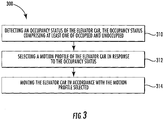
- FIG. 3 shows a flow diagram illustrating a method 300 of operating the elevator system 100 of FIG. 1 and 2 , according to an embodiment of the present disclosure.
- an occupancy status of an elevator car 114 is detected.
- the occupancy status comprises at least one of occupied and unoccupied.
- the elevator system 100 detects that the occupancy status using at least one of a visual detection device, a weight detection device, a laser detection device, a thermal image detection device, a depth detection device, a motion detection device, an odor detection device, a RADAR device, an ultrasonic sensor, and a pyroelectric sensor.
- the occupancy status is continuously detected and updated throughout the movement of the elevator car 114.
- a motion profile of the elevator car 114 is selected in response to the occupancy status.
- the motion profile comprises at least one of an unoccupied motion profile, an occupied motion profile, an occupied lateral movement motion profile, a power-save motion profile, and an occupied descent motion profile.
- the unoccupied motion profile allows the elevator car 114 to operate using a motion parameter having a greater magnitude than a comparable motion parameter of the occupied motion profile when the occupancy status detected is occupied. For instance, a speed is comparable to another speed, an acceleration is comparable to another acceleration, a jerk is comparable to another jerk, and so on and so forth.
- the elevator car 114 is able to accelerate and decelerate faster operating in the unoccupied motion profile than the occupied motion profile.
- the elevator car 114 will accelerate and decelerate slower when operating in the occupied motion profile in comparison to the unoccupied motion profile to ensure passenger comfort.
- the motion profile places limits on motion parameters of the elevator car 114 to ensure passenger comfort.
- Motion parameters may include but are not limited to speed, acceleration, and jerk of the elevator car 114. Any further derivatives of the position of the elevator car 114 may also be included in the motion parameters.
- the occupied lateral movement motion profile allows the elevator car 114 to operate using a motion parameter having a smaller magnitude than a comparable motion parameter of the occupied motion profile when the occupancy status detected is occupied and the direction of travel includes a lateral motion.
- the elevator car 114 will accelerate and decelerate slower when operating in the lateral occupied motion profile in comparison to the occupied motion profile due to decreased passenger stability in the lateral direction 188.
- the occupied descent motion profile allows the elevator car 114 to operate using a motion parameter having a smaller magnitude than a comparable motion parameter of the occupied motion profile when the occupancy status detected is occupied and the direction of travel includes a downward motion.
- the elevator car 114 may reduce its velocity when descending with passengers.
- the power-save motion profile allows the elevator car 114 to operate using a motion parameter having a smaller magnitude than a comparable motion parameter of the occupied motion profile when the occupancy status detected is unoccupied.
- the elevator car 114 may move at a slower velocity when unoccupied in order to save power.
- the system controller 125 also may adjust the motion profile based on whether there are passengers within the elevator car 114.
- the occupied motion profile may be used when there are passengers in the elevator car 114 and the unoccupied motion profile may be used when there are no passengers in the elevator car 114.
- the unoccupied motion profile allows the elevator car 114 to travel through the route segment faster. For instance, the elevator car 114 may be allowed to accelerate faster than would typically be allowed with passengers.
- the unoccupied motion profile may also allow more jerk in the elevator car 114 than would typically be allowed with passengers.
- the elevator car 114 is moved in accordance with the motion profile selected.
- the elevator car is moved along a route.
- the route is composed of at least one route segment.
- a route segment may be that the elevator car 114 moves from a first floor to a second floor.
- the route may be determined prior to moving the elevator car 114.
- the route is determined by the system controller 125 and the route execution is monitored by the on-board controller 156 to ensure that the route is carried out.
- the route is determined for the elevator car 114 after receiving an elevator call from a floor 140 and the route includes a stop for the elevator car at the floor 140.
- the route is determined for the elevator car 114 after receiving destination floor car call, such as, for example a passenger within the elevator car 114 pressing a button to select a destination floor.
- An elevator call may be a passenger pressing an elevator call button on the floor 140 requesting the elevator car 114 come to the floor 140 to pick up the passenger.
Landscapes
- Engineering & Computer Science (AREA)
- Automation & Control Theory (AREA)
- Structural Engineering (AREA)
- Civil Engineering (AREA)
- Mechanical Engineering (AREA)
- Elevator Control (AREA)
Abstract
Description
- The subject matter disclosed herein generally relates to the field of elevators, and more particularly to an apparatus and method operating an elevator car.
In order to ensure passenger comfort elevator systems commonly place limits on many motion parameters of an elevator car including but not limited to speed, acceleration, and jerk. - According to one embodiment, a method of operating an elevator system is provided. The method comprising: detecting an occupancy status of the elevator car, the occupancy status comprising at least one of occupied and unoccupied; selecting a motion profile of the elevator car in response to the occupancy status, the motion profile comprising at least one of an unoccupied motion profile, an occupied motion profile, an occupied lateral movement motion profile, a power-save motion profile, and an occupied descent motion profile; and moving the elevator car in accordance with the motion profile selected.
- In addition to one or more of the features described above, or as an alternative, further embodiments of the method may include that the unoccupied motion profile allows the elevator car to operate using a motion parameter having a greater magnitude than a comparable motion parameter of the occupied motion profile.
- In addition to one or more of the features described above, or as an alternative, further embodiments of the method may include: detecting a direction of travel of an elevator car; wherein the occupied lateral movement motion profile allows the elevator car to operate using a motion parameter having a smaller magnitude than a comparable motion parameter of the occupied motion profile.
- In addition to one or more of the features described above, or as an alternative, further embodiments of the method may include: detecting a direction of travel of an elevator car; wherein the occupied descent motion profile allows the elevator car to operate using a motion parameter having a smaller magnitude than a comparable motion parameter of the occupied motion profile.
- In addition to one or more of the features described above, or as an alternative, further embodiments of the method may include that the power-save motion profile allows the elevator car to operate using a motion parameter having a smaller magnitude than a comparable motion parameter of the occupied motion profile.
- In addition to one or more of the features described above, or as an alternative, further embodiments of the method may include that the motion parameters include at least one of a speed of the elevator car, an acceleration of the elevator car, and a jerk of the elevator car.
- In addition to one or more of the features described above, or as an alternative, further embodiments of the method may include that the elevator system is a ropeless multi-car elevator system.
- In addition to one or more of the features described above, or as an alternative, further embodiments of the method may include that the elevator system detects that the occupancy status using at least one of a visual detection device, a weight detection device, a laser detection device, a thermal image detection device, a depth detection device, a motion detection device, an odor detection device, a RADAR device, an ultrasonic sensor, and a pyroelectric sensor.
- In addition to one or more of the features described above, or as an alternative, further embodiments of the method may include that the occupancy status is continuously detected and updated throughout the movement of the elevator car.
- According to another embodiment, an elevator system is provided. The elevator system comprising: a processor; a memory comprising computer-executable instructions that, when executed by the processor, cause the processor to perform operations. The operations comprising: detecting an occupancy status of the elevator car, the occupancy status comprising at least one of occupied and unoccupied; selecting a motion profile of the elevator car in response to the occupancy status, the motion profile comprising at least one of an unoccupied motion profile, an occupied motion profile, an occupied lateral movement motion profile, a power-save motion profile, and an occupied descent motion profile; and moving the elevator car in accordance with the motion profile selected.
- In addition to one or more of the features described above, or as an alternative, further embodiments of the elevator system may include that the unoccupied motion profile allows the elevator car to operate using a motion parameter having a greater magnitude than a comparable motion parameter of the occupied motion profile.
- In addition to one or more of the features described above, or as an alternative, further embodiments of the elevator system may include that the operations further comprise: detecting a direction of travel of an elevator car; wherein the occupied lateral movement motion profile allows the elevator car to operate using a motion parameter having a smaller magnitude than a comparable motion parameter of the occupied motion profile.
- In addition to one or more of the features described above, or as an alternative, further embodiments of the elevator system may include that the operations further comprise: detecting a direction of travel of an elevator car; wherein the occupied descent motion profile allows the elevator car to operate using a motion parameter having a smaller magnitude than a comparable motion parameter of the occupied motion profile.
- In addition to one or more of the features described above, or as an alternative, further embodiments of the elevator system may include that the power-save motion profile allows the elevator car to operate using a motion parameter having a smaller magnitude than a comparable motion parameter of the occupied motion profile.
- In addition to one or more of the features described above, or as an alternative, further embodiments of the elevator system may include that the motion parameters include at least one of a speed of the elevator car, an acceleration of the elevator car, and a jerk of the elevator car.
- In addition to one or more of the features described above, or as an alternative, further embodiments of the elevator system may include that the elevator system is a ropeless multi-car elevator system.
- In addition to one or more of the features described above, or as an alternative, further embodiments of the elevator system may include that the elevator system detects that the occupancy status using at least one of a visual detection device, a weight detection device, a laser detection device, a thermal image detection device, a depth detection device, a motion detection device, an odor detection device, a RADAR device, an ultrasonic sensor, and a pyroelectric sensor.
- In addition to one or more of the features described above, or as an alternative, further embodiments of the elevator system may include that the occupancy status is continuously detected and updated throughout the movement of the elevator car.
- According to another embodiment, a computer program product tangibly embodied on a computer readable medium is provided. The computer program product including instructions that, when executed by a processor, cause the processor to perform operations comprising: detecting an occupancy status of the elevator car, the occupancy status comprising at least one of occupied and unoccupied; selecting a motion profile of the elevator car in response to the occupancy status, the motion profile comprising at least one of an unoccupied motion profile, an occupied motion profile, an occupied lateral movement motion profile, a power-save motion profile, and an occupied descent motion profile; and moving the elevator car in accordance with the motion profile selected.
- In addition to one or more of the features described above, or as an alternative, further embodiments of the computer program may include that the unoccupied motion profile allows the elevator car to operate using a motion parameter having a greater magnitude than a comparable motion parameter of the occupied motion profile.
- Technical effects of embodiments of the present disclosure include adjusting the motion profile of an elevator car when the elevator car is empty so that the elevator car could reach a destination faster.
- The foregoing features and elements may be combined in various combinations without exclusivity, unless expressly indicated otherwise. These features and elements as well as the operation thereof will become more apparent in light of the following description and the accompanying drawings. It should be understood, however, that the following description and drawings are intended to be illustrative and explanatory in nature and non-limiting.
- The following descriptions should not be considered limiting in any way. With reference to the accompanying drawings, like elements are numbered alike:
-
FIG. 1 illustrates a schematic view of a multicar elevator system, in accordance with an embodiment of the disclosure; -
FIG. 2 illustrates an enlarged schematic view of a single elevator car within the multicar elevator system ofFIG. 1 , in accordance with an embodiment of the disclosure; and -
FIG. 3 is a flow diagram illustrating a method of operating the multi-car elevator system ofFIG. 1 and2 , according to an embodiment of the present disclosure. - A detailed description of one or more embodiments of the disclosed apparatus and method are presented herein by way of exemplification and not limitation with reference to the Figures.
-
FIG. 1 depicts a multicar,ropeless elevator system 100 that may be employed with embodiments of the present disclosure. As will be appreciated by those of skill in the art,FIG. 1 depicts a multicar,ropeless elevator system 100, however the embodiments disclosed herein may be incorporated with other elevator systems that are not multicar, ropeless elevator systems or that include any other known elevator configuration. In addition, anelevator car 114 of theelevator system 100 may include two or more compartments (ex: double deck elevator). As seen inFIG. 1 , theelevator system 100 includes anelevator shaft 111 having a plurality oflanes lanes FIG. 1 , it is understood that various embodiments of the present disclosure and various configurations of a multicar, ropeless elevator system may include any number of lanes, either more or fewer than the three lanes shown inFIG. 1 . In eachlane multiple elevator cars 114 can travel in one direction, i.e., up as shown byarrow 184 or down as shown byarrow 182, or multiple cars within a single lane may be configured to move in opposite directions, as shown byarrow 186. For example, inFIG. 1 elevator cars 114 inlanes arrow 184 andelevator cars 114 inlane 117 travel down in the direction ofarrow 182. Further, as shown inFIG. 1 , one ormore elevator cars 114 may travel in asingle lane - As shown, above the top accessible floor of the building is an
upper transfer station 130 configured to impart lateral motion in the direction ofarrow 188 to theelevator cars 114 to move theelevator cars 114 betweenlanes arrow 188 and diagonal lateral motion as shown byarrow 189 andarrow 187. Lateral motion may be undertaken by theelevator car 114 without a transfer station, such as, for example an elevator system serving pyramid shaped buildings. It is understood thatupper transfer station 130 may be located at the top floor, rather than above the top floor. Similarly, below the first floor of the building is alower transfer station 132 configured to impart lateral motion to theelevator cars 114 to move theelevator cars 114 betweenlanes lower transfer station 132 may be located on the first floor, rather than below the first floor. Although not shown inFIG. 1 , one or more intermediate transfer stations may be configured between thelower transfer station 132 and theupper transfer station 130. Intermediate transfer stations are similar to theupper transfer station 130 andlower transfer station 132 and are configured to impart lateral motion to theelevator cars 114 at the respective transfer station, thus enabling transfer from one lane to another lane at an intermediary point within theelevator shaft 111. Further, although not shown inFIG. 1 , theelevator cars 114 are configured to stop at a plurality offloors 140 to allow ingress to and egress from theelevator cars 114. - In the illustrated embodiment the
elevator system 100 includes a designatedparking area 180. The designatedparking area 180 may be used to storeelevator cars 114 when not in use. As shown inFIG. 1 , the designatedparking area 180 may be located below the first floor of the building, however it is understood that the designatedparking area 180 may be located on any other floor of the building or also above the top floor of the building. If anelevator system 100 does not include a designatedparking area 180 then one of thelanes elevators cars 114. -
Elevator cars 114 are propelled withinlanes first part 116, and a secondary, moving portion, orsecond part 118. Thefirst part 116 is a fixed part because it is mounted to a portion of the lane, and thesecond part 118 is a moving part because it is mounted on theelevator car 114 that is movable within the lane. - The
first part 116 includes windings or coils mounted on astructural member 119, and may be mounted at one or both sides of thelanes elevator cars 114. - The
second part 118 includes permanent magnets mounted to one or both sides ofcars 114, i.e., on the same sides as thefirst part 116. Thesecond part 118 engages with thefirst part 116 to support and drive theelevators cars 114 within thelanes First part 116 is supplied with drive signals from one ormore drive units 120 to control movement ofelevator cars 114 in their respective lanes through the linear, permanent magnet motor system. Thesecond part 118 operably connects with and electromagnetically operates with thefirst part 116 to be driven by the signals and electrical power. The drivensecond part 118 enables theelevator cars 114 to move along thefirst part 116 and thus move within alane - Those of skill in the art will appreciate that the
first part 116 andsecond part 118 are not limited to this example. In alternative embodiments, thefirst part 116 may be configured as permanent magnets, and thesecond part 118 may be configured as windings or coils. Further, those of skill in the art will appreciate that other types of propulsion may be used without departing from the scope of the present disclosure. - The
first part 116 is formed from a plurality of motor segments 122 (seen inFIG. 2 ), with each segment associated with adrive unit 120. Although not shown, thecentral lane 115 ofFIG. 1 also includes a drive unit for each segment of thefirst part 116 that is within thelane 115. Those of skill in the art will appreciate that although adrive unit 120 is provided for each motor segment 122 (seen inFIG. 2 ) of the system (one-to-one) other configurations may be used without departing from the scope of the present disclosure. Further, those of skill in the art will appreciate that other types of propulsion may be employed without departing from the scope of the present disclosure. For example, a magnetic screw may be used for a propulsion system of elevator cars. Those of skill in the art will also appreciate that the embodiments disclosed herein may also be applied to roped elevator systems and hydraulically operated elevator systems. Thus, the described and shown propulsion system of this disclosure is merely provided for explanatory purposes, and is not intended to be limiting. - Turning now to
FIG. 2 , a view of anelevator system 110 including anelevator car 114 that travels inlane 113 is shown.Elevator car 114 is guided by one ormore guide rails 124 extending along the length oflane 113, where theguide rails 124 may be affixed to astructural member 119. For ease of illustration, the view ofFIG. 2 only depicts asingle guide rail 124; however, there may be any number of guide rails positioned within thelane 113 and may, for example, be positioned on opposite sides of theelevator car 114.Elevator system 110 employs a linear propulsion system as described above, where afirst part 116 includesmultiple motor segments first part 116 may be mounted to guiderail 124, incorporated into theguide rail 124, or may be located apart fromguide rail 124 onstructural member 119. Thefirst part 116 serves as a stator of a permanent magnet synchronous linear motor to impart force toelevator car 114. Thesecond part 118, as shown inFIG. 2 , is mounted to theelevator car 114 and includes an array of one or morepermanent magnets 128 to form a second portion of the linear propulsion system of the ropeless elevator system.Coils 126 ofmotor segments first parts 116 may be mounted in thelane 113, to co-act withpermanent magnets 128 mounted toelevator car 114. Although only a single side ofelevator car 114 is shown withpermanent magnets 128 the example ofFIG. 2 , thepermanent magnets 128 may be positioned on two or more sides ofelevator car 114. Alternate embodiments may use a singlefirst part 116/second part 118 configuration, or multiplefirst part 116/second part 118 configurations. - In the example of
FIG. 2 , there are fourmotor segments motor segments drive system controller 125 provides drive signals to themotor segments drives elevator car 114. Thesystem controller 125 may be implemented using a microprocessor executing a computer program stored on a storage medium to perform the operations described herein. Alternatively, thesystem controller 125 may be implemented in hardware (e.g., field programmable gate array (FPGA), application specific integrated circuits (ASIC),) or in a combination of hardware/software. Thesystem controller 125 may include power circuitry (e.g., an inverter or drive) to power thefirst part 116. Although asingle system controller 125 is depicted, it will be understood by those of ordinary skill in the art that a plurality of system controllers may be used. For example, a single system controller may be provided to control the operation of a group of motor segments over a relatively short distance, and in some embodiments a single system controller may be provided for each drive unit or group of drive units, with the system controllers in communication with each other. In an embodiment, thesystem controller 125 controls the simultaneous operation ofmultiple elevator cars 114. - In some embodiments, as shown in
FIG. 2 , theelevator car 114 includes an on-board controller 156 with one ormore transceivers 138 and a processor, or CPU, 134. The on-board controller 156 and thesystem controller 125 collectively form a control system where computational processing may be shifted between the on-board controller 156 and thesystem controller 125. - The on-
board controller 156 and thesystem controller 125 may each include at least one processor and at least one associated memory comprising computer-executable instructions that, when executed by the processor, cause the processor to perform various operations. The processor may be but is not limited to a single-processor or multi-processor system of any of a wide array of possible architectures, including FPGA, central processing unit (CPU), ASIC, digital signal processor (DSP) or graphics processing unit (GPU) hardware arranged homogenously or heterogeneously. The memory may be a storage device such as, for example, a random access memory (RAM), read only memory (ROM), or other electronic, optical, magnetic or any other computer readable medium. - In some embodiments, the
processor 134 of on-board controller 156 is configured to monitor one or more sensors (ex:occupancy detection system 190 discussed further below) and to communicate with one ormore system controllers 125 via thetransceivers 138. In some embodiments, to ensure reliable communication,elevator car 114 may include at least twotransceivers 138 configured for redundancy of communication. Thetransceivers 138 can be set to operate at different frequencies, or communication channels, to minimize interference and to provide full duplex communication between theelevator car 114 and the one ormore system controllers 125. In the example ofFIG. 2 , the on-board controller 156 interfaces with aload sensor 152 to detect an elevator load on abrake 136. Thebrake 136 may engage with thestructural member 119, aguide rail 124, or other structure in thelane 113. Although the example ofFIG. 2 depicts only asingle load sensor 152 andbrake 136,elevator car 114 can includemultiple load sensors 152 andbrakes 136. - In an embodiment, the
elevator car 114 may include anoccupancy detection system 190 in operable communication with the on-board controller 156. Theoccupancy detection system 190 is configured to detect the occupancy status of theelevator car 114. The occupancy status may be at least one of occupied or unoccupied. In an embodiment, the occupancy status may be continually update through the movement of theelevator car 114. Occupied may mean that there are passengers in the elevator car 23 and/or particular objects that require safe handling. An object that requires safe handling may be an object such as, for example, an object on wheels that may move in the elevator or an object with a high center of gravity that may tip over in the elevator. In an alternate embodiment, the occupancy status may be fine-tuned further to differentiate between different types of passengers, such as, for example younger thrill seekers who might enjoy a faster elevator ride as opposed to someone using a walking cane who might require a gentler elevator ride. Unoccupied may mean that theelevator car 114 is free of passengers and/or objects that require safe handling. - The
occupancy detection system 190 may use a variety of ranging sensors and/or presence detection devices such as, for example, a visual detection device, a weight detection device, a laser detection device, a thermal image detection device, a depth detection device, a motion detection device, an odor detection device, RADAR, ultrasonic sensor, and pyroelectric sensors. The visual detection device may be a camera that utilizes visual recognition to identify individual passengers and/or objects in theelevator car 114. The weight detection device may be a scale to sense the amount of weight in anelevator car 114 and then determine if passengers and/or objects are present from the weight sensed. The laser detection device may detect how many passengers walk through a laser beam to determine if there are passengers present in theelevator car 114. The thermal detection device may be an infrared or other heat sensing camera that utilizes detected temperature to identify individual passengers and objects in theelevator car 114. The depth detection device may be a 2-D, 3-D, ranging or other depth/distance detecting sensor that utilizes the detected distance to an object and/or passenger to determine if anything is present in anelevator car 114. One example of a depth detection device is LIDAR (Light Detection and Ranging). The motion detection device may be a motion detection sensor to detect motion in theelevator car 114 and determine if a passenger is present in theelevator car 114. The odor detection device may be an odor detector configured to determine if a passenger and/or object is present in theelevator car 114 such as, for example an electronic nose. As may be appreciated by one of skill in the art, in addition to the stated methods, additional methods may exist to detect passengers and one or any combination of these methods may be used to determine whether there are passengers and/or object in theelevator car 114. - Advantageously by being able to detect whether there are passengers in the
elevator car 114, a motion profile of theelevator car 114 may be adjusted. Theelevator car 114 moves according to the motion profile dictated by thesystem controller 125. The motion profile will place limits on motion parameters of theelevator car 114 to ensure passenger comfort. Motion parameters may include but are not limited to speed, acceleration, and jerk of theelevator car 114. Any further derivatives of the position of theelevator car 114 may also be included in the motion parameters. Thesystem controller 125 may adjust the motion profile depending on the direction of travel of theelevator car 114. For instance, the motion profile may include motion parameters with a smaller magnitude when traveling laterally with passengers due to decreased passenger stability in the lateral direction as seen byarrow 188. For example, theelevator car 114 will accelerate and decelerate slower when operating in the lateral occupied motion profile in comparison to the occupied motion profile due to the decreased passenger stability in thelateral direction 188. Thus, the limits on speed, acceleration and jerk may be decreased when traveling in the lateral direction. - The
system controller 125 also may adjust the motion profile based on whether there are passengers within theelevator car 114 and thus there may be an occupied motion profile and an unoccupied motion profile. The occupied motion profile may be used when there are passengers in theelevator car 114 and the unoccupied motion profile may be used when there are no passengers in theelevator car 114. The unoccupied motion profile may include motion parameters with a higher magnitude than the occupied motion profile. Advantageously, the unoccupied motion profile allows theelevator car 114 travel through the route faster. For example, theelevator car 114 is able to accelerate and decelerate faster operating in the unoccupied motion profile than the occupied motion profile. The unoccupied motion profile may also allow more jerk in theelevator car 114 than would typically be allowed with passengers. In another embodiment, there may be a power-save motion profile configured to help the elevator system save power when there is no demand for the elevator car. In the power-save motion profile the elevator car may operate with a motion parameter having a smaller magnitude than a comparable motion parameter of the occupied motion profile. For instance, operating theelevator car 114 at a lower speed allows theelevator system 100 to save power. Further there may also be an occupied descent motion profile that may operate with motioning parameters having a smaller magnitude than comparable motion parameters of the occupied motion profile. The occupied descent motion profile may be used when theelevator car 114 is determined to be occupied and traveling in the downward direction, as shown byarrow 182. For example, the occupied descent motion profile may help slow the velocity of theelevator car 114 so that it does not descend too fast. - Turning now to
FIG. 3 while continuing to referenceFIGs. 1-2 ,FIG. 3 shows a flow diagram illustrating amethod 300 of operating theelevator system 100 ofFIG. 1 and2 , according to an embodiment of the present disclosure. Atblock 310, an occupancy status of anelevator car 114 is detected. As mentioned above, the occupancy status comprises at least one of occupied and unoccupied. In an embodiment, theelevator system 100 detects that the occupancy status using at least one of a visual detection device, a weight detection device, a laser detection device, a thermal image detection device, a depth detection device, a motion detection device, an odor detection device, a RADAR device, an ultrasonic sensor, and a pyroelectric sensor. In another embodiment, the occupancy status is continuously detected and updated throughout the movement of theelevator car 114. - At
block 312, a motion profile of theelevator car 114 is selected in response to the occupancy status. As mentioned above, the motion profile comprises at least one of an unoccupied motion profile, an occupied motion profile, an occupied lateral movement motion profile, a power-save motion profile, and an occupied descent motion profile. - In an embodiment, the unoccupied motion profile allows the
elevator car 114 to operate using a motion parameter having a greater magnitude than a comparable motion parameter of the occupied motion profile when the occupancy status detected is occupied. For instance, a speed is comparable to another speed, an acceleration is comparable to another acceleration, a jerk is comparable to another jerk, and so on and so forth. In one example, theelevator car 114 is able to accelerate and decelerate faster operating in the unoccupied motion profile than the occupied motion profile. In another example, theelevator car 114 will accelerate and decelerate slower when operating in the occupied motion profile in comparison to the unoccupied motion profile to ensure passenger comfort. As described above, the motion profile places limits on motion parameters of theelevator car 114 to ensure passenger comfort. Motion parameters may include but are not limited to speed, acceleration, and jerk of theelevator car 114. Any further derivatives of the position of theelevator car 114 may also be included in the motion parameters. - In an embodiment, the occupied lateral movement motion profile allows the
elevator car 114 to operate using a motion parameter having a smaller magnitude than a comparable motion parameter of the occupied motion profile when the occupancy status detected is occupied and the direction of travel includes a lateral motion. For example, theelevator car 114 will accelerate and decelerate slower when operating in the lateral occupied motion profile in comparison to the occupied motion profile due to decreased passenger stability in thelateral direction 188. - In an embodiment, the occupied descent motion profile allows the
elevator car 114 to operate using a motion parameter having a smaller magnitude than a comparable motion parameter of the occupied motion profile when the occupancy status detected is occupied and the direction of travel includes a downward motion. For example, theelevator car 114 may reduce its velocity when descending with passengers. In an embodiment, the power-save motion profile allows theelevator car 114 to operate using a motion parameter having a smaller magnitude than a comparable motion parameter of the occupied motion profile when the occupancy status detected is unoccupied. For example, theelevator car 114 may move at a slower velocity when unoccupied in order to save power. - As mentioned above, the
system controller 125 also may adjust the motion profile based on whether there are passengers within theelevator car 114. The occupied motion profile may be used when there are passengers in theelevator car 114 and the unoccupied motion profile may be used when there are no passengers in theelevator car 114. Advantageously, the unoccupied motion profile allows theelevator car 114 to travel through the route segment faster. For instance, theelevator car 114 may be allowed to accelerate faster than would typically be allowed with passengers. The unoccupied motion profile may also allow more jerk in theelevator car 114 than would typically be allowed with passengers. - At
block 314, theelevator car 114 is moved in accordance with the motion profile selected. In an embodiment, the elevator car is moved along a route. The route is composed of at least one route segment. For example, a route segment may be that theelevator car 114 moves from a first floor to a second floor. The route may be determined prior to moving theelevator car 114. In an embodiment, the route is determined by thesystem controller 125 and the route execution is monitored by the on-board controller 156 to ensure that the route is carried out. In another embodiment, the route is determined for theelevator car 114 after receiving an elevator call from afloor 140 and the route includes a stop for the elevator car at thefloor 140. In another embodiment, the route is determined for theelevator car 114 after receiving destination floor car call, such as, for example a passenger within theelevator car 114 pressing a button to select a destination floor. An elevator call may be a passenger pressing an elevator call button on thefloor 140 requesting theelevator car 114 come to thefloor 140 to pick up the passenger. - While the above description has described the flow process of
FIG. 3 in a particular order, it should be appreciated that unless otherwise specifically required in the attached claims that the ordering of the steps may be varied. - The term "about" is intended to include the degree of error associated with measurement of the particular quantity based upon the equipment available at the time of filing the application. For example, "about" can include a range of ± 8% or 5%, or 2% of a given value.
- The terminology used herein is for the purpose of describing particular embodiments only and is not intended to be limiting of the present disclosure. As used herein, the singular forms "a", "an" and "the" are intended to include the plural forms as well, unless the context clearly indicates otherwise. It will be further understood that the terms "comprises" and/or "comprising," when used in this specification, specify the presence of stated features, integers, steps, operations, elements, and/or components, but do not preclude the presence or addition of one or more other features, integers, steps, operations, element components, and/or groups thereof.
- While the present disclosure has been described with reference to an exemplary embodiment or embodiments, it will be understood by those skilled in the art that various changes may be made and equivalents may be substituted for elements thereof without departing from the scope of the present disclosure. In addition, many modifications may be made to adapt a particular situation or material to the teachings of the present disclosure without departing from the essential scope thereof. Therefore, it is intended that the present disclosure not be limited to the particular embodiment disclosed as the best mode contemplated for carrying out this present disclosure, but that the present disclosure will include all embodiments falling within the scope of the claims.
Claims (15)
- A method of operating an elevator system, the method comprising:detecting an occupancy status of the elevator car, the occupancy status comprising at least one of occupied and unoccupied;selecting a motion profile of the elevator car in response to the occupancy status, the motion profile comprising at least one of an unoccupied motion profile, an occupied motion profile, an occupied lateral movement motion profile, a power-save motion profile, and an occupied descent motion profile; andmoving the elevator car in accordance with the motion profile selected.
- The method of claim 1, wherein:the unoccupied motion profile allows the elevator car to operate using a motion parameter having a greater magnitude than a comparable motion parameter of the occupied motion profile.
- The method of claim 1 or 2, further comprising:detecting a direction of travel of an elevator car;wherein the occupied lateral movement motion profile allows the elevator car to operate using a motion parameter having a smaller magnitude than a comparable motion parameter of the occupied motion profile; and/orwherein the occupied descent motion profile allows the elevator car to operate using a motion parameter having a smaller magnitude than a comparable motion parameter of the occupied motion profile.
- The method of any of claims 1 to 3, wherein:the power-save motion profile allows the elevator car to operate using a motion parameter having a smaller magnitude than a comparable motion parameter of the occupied motion profile.
- The method of any of claims 1 to 4, wherein:the motion parameters include at least one of a speed of the elevator car, an acceleration of the elevator car, and a jerk of the elevator car.
- The method of any of claims 1 to 5, wherein:the elevator system is a ropeless multi-car elevator system.
- The method of any of claims 1 to 6, wherein:the elevator system detects that the occupancy status using at least one of a visual detection device, a weight detection device, a laser detection device, a thermal image detection device, a depth detection device, a motion detection device, an odor detection device, a RADAR device, an ultrasonic sensor, and a pyroelectric sensors.
- The method of any of claims 1 to 7, wherein
the occupancy status is continuously detected and updated throughout the movement of the elevator car. - An elevator system comprising:a processor;a memory comprising computer-executable instructions that, when executed by the processor, cause the processor to perform operations, the operations comprising:detecting an occupancy status of the elevator car, the occupancy status comprising at least one of occupied and unoccupied;selecting a motion profile of the elevator car in response to the occupancy status, the motion profile comprising at least one of an unoccupied motion profile, an occupied motion profile, an occupied lateral movement motion profile, a power-save motion profile, and an occupied descent motion profile; andmoving the elevator car in accordance with the motion profile selected.
- The elevator system of claim 9, wherein:the unoccupied motion profile allows the elevator car to operate using a motion parameter having a greater magnitude than a comparable motion parameter of the occupied motion profile.
- The elevator system of claim 9 or 10, wherein the operations further comprise:detecting a direction of travel of an elevator car;wherein the occupied lateral movement motion profile allows the elevator car to operate using a motion parameter having a smaller magnitude than a comparable motion parameter of the occupied motion profile; and/orwherein the occupied descent motion profile allows the elevator car to operate using a motion parameter having a smaller magnitude than a comparable motion parameter of the occupied motion profile.
- The elevator system of any of claims 9 to 11, wherein:the power-save motion profile allows the elevator car to operate using a motion parameter having a smaller magnitude than a comparable motion parameter of the occupied motion profile; and/orthe motion parameters include at least one of a speed of the elevator car, an acceleration of the elevator car, and a jerk of the elevator car.
- The elevator system of any of claims 9 to 12, wherein:the elevator system is a ropeless multi-car elevator system.
- The elevator system of any of claims 9 to 13, wherein:the elevator system detects that the occupancy status using at least one of a visual detection device, a weight detection device, a laser detection device, a thermal image detection device, a depth detection device, a motion detection device, an odor detection device, a RADAR device, an ultrasonic sensor, and a pyroelectric sensors; and/orthe occupancy status is continuously detected and updated throughout the movement of the elevator car.
- A computer program product tangibly embodied on a computer readable medium, the computer program product including instructions that, when executed by a processor, cause the processor to perform operations according to the method of any of claims 1 to 8.
Applications Claiming Priority (1)
| Application Number | Priority Date | Filing Date | Title |
|---|---|---|---|
| US15/374,343 US10081513B2 (en) | 2016-12-09 | 2016-12-09 | Motion profile for empty elevator cars and occupied elevator cars |
Publications (2)
| Publication Number | Publication Date |
|---|---|
| EP3345851A1 true EP3345851A1 (en) | 2018-07-11 |
| EP3345851B1 EP3345851B1 (en) | 2025-05-07 |
Family
ID=60515285
Family Applications (1)
| Application Number | Title | Priority Date | Filing Date |
|---|---|---|---|
| EP17204657.5A Active EP3345851B1 (en) | 2016-12-09 | 2017-11-30 | Motion profile for empty elevator cars and occupied elevator cars |
Country Status (3)
| Country | Link |
|---|---|
| US (1) | US10081513B2 (en) |
| EP (1) | EP3345851B1 (en) |
| CN (1) | CN108217358B (en) |
Cited By (2)
| Publication number | Priority date | Publication date | Assignee | Title |
|---|---|---|---|---|
| EP3960676A1 (en) * | 2020-08-26 | 2022-03-02 | Otis Elevator Company | Elevator smoke and fire detection system |
| KR20230122809A (en) * | 2022-02-15 | 2023-08-22 | 현대무벡스 주식회사 | Circulation type vertical transport system and method for controlling the same |
Families Citing this family (5)
| Publication number | Priority date | Publication date | Assignee | Title |
|---|---|---|---|---|
| WO2017168035A1 (en) * | 2016-03-30 | 2017-10-05 | Kone Corporation | A method, a safety control unit, and an elevator system for verifying speed data of an elevator car for overspeed monitoring of the elevator car |
| US10399815B2 (en) * | 2016-06-07 | 2019-09-03 | Otis Elevator Company | Car separation control in multi-car elevator system |
| DE102017219146A1 (en) * | 2017-10-25 | 2019-04-25 | Thyssenkrupp Ag | Elevator installation with shaft changing units and method for operating an elevator installation with shaft changing units |
| DE102018213575B4 (en) * | 2018-08-13 | 2020-03-19 | Thyssenkrupp Ag | Method for operating an elevator system with specification of a predetermined route as well as elevator system and elevator control for executing such a method |
| CN117550448B (en) * | 2023-10-24 | 2024-08-06 | 深圳市瀚强科技股份有限公司 | Intelligent processing method and related device for elevator information |
Citations (5)
| Publication number | Priority date | Publication date | Assignee | Title |
|---|---|---|---|---|
| US5241141A (en) * | 1990-09-17 | 1993-08-31 | Otis Elevator Company | Elevator profile selection based on absence or presence of passengers |
| WO2006043926A1 (en) * | 2004-10-14 | 2006-04-27 | Otis Elevator Company | Elevation motion profile control for limiting power consumption |
| WO2008079147A1 (en) * | 2006-12-22 | 2008-07-03 | Otis Elevator Company | Elevator system with multiple cars in a single hoistway |
| US20120111670A1 (en) * | 2009-07-15 | 2012-05-10 | Otis Elevator Company | Energy savings with optimized motion profiles |
| DE112010005324T5 (en) * | 2010-03-03 | 2012-12-27 | Mitsubishi Electric Corporation | Control device for an elevator |
Family Cites Families (56)
| Publication number | Priority date | Publication date | Assignee | Title |
|---|---|---|---|---|
| US1943119A (en) * | 1929-12-17 | 1934-01-09 | Westinghouse Electric & Mfg Co | Circuitous elevator |
| US1939729A (en) * | 1930-01-29 | 1933-12-19 | Thomas W Cohill | Elevator system |
| US4004654A (en) * | 1971-07-07 | 1977-01-25 | Trebron Holdings Limited | Elevator structure supporting apparatus |
| FR2576888B1 (en) * | 1985-02-05 | 1988-04-08 | Otis Elevator Co | TRANSPORTER ELEVATOR FOR URBAN WAYS, ESPECIALLY |
| JP3029168B2 (en) | 1993-04-22 | 2000-04-04 | 株式会社日立製作所 | Operation control device for multi-car type elevator |
| JPH07187525A (en) | 1993-11-18 | 1995-07-25 | Masami Sakita | Elevator system with plural cars |
| US5601156A (en) * | 1995-11-29 | 1997-02-11 | Otis Elevator Company | Maintaining communications and power during transfer of horizontally moveable elevator cab |
| US5651426A (en) * | 1995-11-29 | 1997-07-29 | Otis Elevator Company | Synchronous elevator shuttle system |
| US5758748A (en) * | 1995-11-29 | 1998-06-02 | Otis Elevator Company | Synchronized off-shaft loading of elevator cabs |
| US5861586A (en) * | 1996-06-19 | 1999-01-19 | Otis Elevator Company | Horizontal and vertical passenger transport |
| US5924524A (en) * | 1996-07-25 | 1999-07-20 | Otis Elevator Company | Integrated, multi-level elevator shuttle |
| US5752585A (en) * | 1996-07-25 | 1998-05-19 | Otis Elevator Company | Elevator shuttle with auxiliary elevators at terminals |
| JP4505901B2 (en) | 1999-11-05 | 2010-07-21 | 三菱電機株式会社 | Elevator control device |
| JP4086565B2 (en) | 2001-07-06 | 2008-05-14 | 三菱電機株式会社 | Operation control system for single-shaft multi-car elevator system |
| JP2004002020A (en) * | 2002-05-27 | 2004-01-08 | Inventio Ag | Elevator facility provided with several self-travelling cars and at least three adjacently arranged elevator hoistways |
| ES2281559T3 (en) * | 2002-11-26 | 2007-10-01 | Thyssenkrupp Elevator Ag | PROCEDURE FOR THE CONTROL OF AN ELEVATOR INSTALLATION, AS WELL AS THE ELEVATOR INSTALLATION TO PERFORM THE PROCEDURE. |
| EP1641697B1 (en) * | 2003-07-09 | 2012-01-18 | Kone Corporation | Counterweight-less elevator |
| US20060163008A1 (en) * | 2005-01-24 | 2006-07-27 | Michael Godwin | Autonomous linear retarder/motor for safe operation of direct drive gearless, rope-less elevators |
| CN101511717B (en) | 2006-06-07 | 2011-05-04 | 奥蒂斯电梯公司 | Elevator system and operation method |
| SG138530A1 (en) | 2006-06-19 | 2008-01-28 | Inventio Ag | Lift installation and method of operating a lift installation |
| KR100898916B1 (en) | 2007-04-02 | 2009-05-26 | 최성식 | System for intelligent elevator and control method thereof |
| CN101801790B (en) | 2007-09-18 | 2012-07-18 | 奥蒂斯电梯公司 | Multi-car hoistway including car separation controller |
| JP5439383B2 (en) | 2007-11-30 | 2014-03-12 | オーチス エレベータ カンパニー | Linking multiple elevator cars in a hoistway |
| ES2393133T3 (en) | 2007-12-05 | 2012-12-18 | Otis Elevator Company | Control strategy for the operation of two elevator cars in a single hole |
| US8424651B2 (en) | 2010-11-17 | 2013-04-23 | Mitsubishi Electric Research Laboratories, Inc. | Motion planning for elevator cars moving independently in one elevator shaft |
| WO2012137346A1 (en) | 2011-04-08 | 2012-10-11 | 三菱電機株式会社 | Multi-car elevator and method for controlling same |
| JP2013170040A (en) | 2012-02-20 | 2013-09-02 | Toshiba Elevator Co Ltd | Elevator system |
| ITTV20130057A1 (en) * | 2013-04-23 | 2014-10-24 | Tarcisio Scomparin | "ELEVATOR AND TRANSLATOR SYSTEM WITH A PORTAL STRUCTURE THAT EMPLOYS RACKS AND MORE VERTICAL AND HORIZONTAL TRAVEL LINES OF AT LEAST ONE TRANSPORT CABIN OF PEOPLE AND THINGS FOR THE OVERCOME OF OBSTACLES RAISED AND NOT." |
| JP6143599B2 (en) | 2013-08-02 | 2017-06-07 | 三菱電機株式会社 | Elevator operation apparatus and elevator operation method |
| WO2015084367A1 (en) * | 2013-12-05 | 2015-06-11 | Otis Elevator Company | High speed ropeless elevator with different number of hoistways up and down in a group |
| US9884744B2 (en) * | 2013-12-05 | 2018-02-06 | Otis Elevator Company | Ropeless high-rise elevator installation approach |
| DE102014201804A1 (en) * | 2014-01-31 | 2015-08-06 | Thyssenkrupp Elevator Ag | Method for operating an elevator system |
| WO2015137967A1 (en) * | 2014-03-14 | 2015-09-17 | Otis Elevator Company | Robust startup method for ropeless elevator |
| CN105329728A (en) * | 2014-06-24 | 2016-02-17 | 沈阳创达技术交易市场有限公司 | Elevator running mode conversion system |
| DE102014220966A1 (en) * | 2014-10-16 | 2016-04-21 | Thyssenkrupp Elevator Ag | Method for operating a transport system and corresponding transport system |
| WO2016060888A1 (en) * | 2014-10-16 | 2016-04-21 | Otis Elevator Company | Lateral transfer station for elevator having a magnetic screw propulsion system |
| DE102014017486A1 (en) * | 2014-11-27 | 2016-06-02 | Thyssenkrupp Ag | Elevator installation with a plurality of cars and a decentralized security system |
| WO2016116146A1 (en) | 2015-01-21 | 2016-07-28 | Kone Corporation | Multi-car elevator system |
| CN104828664B (en) * | 2015-04-03 | 2020-05-22 | 奥的斯电梯公司 | Automatic debugging system and method |
| CN106144796B (en) * | 2015-04-03 | 2020-01-31 | 奥的斯电梯公司 | Depth sensor based occupant sensing for air passenger transport envelope determination |
| CN112850406A (en) * | 2015-04-03 | 2021-05-28 | 奥的斯电梯公司 | Traffic list generation for passenger transport |
| US10370220B2 (en) * | 2015-05-28 | 2019-08-06 | Otis Elevator Company | Flexible destination dispatch passenger support system |
| US10017354B2 (en) * | 2015-07-10 | 2018-07-10 | Otis Elevator Company | Control system for multicar elevator system |
| US10370222B2 (en) * | 2015-07-16 | 2019-08-06 | Otis Elevator Company | Ropeless elevator system and a transfer system for a ropeless elevator system |
| US10135299B2 (en) * | 2015-08-25 | 2018-11-20 | Otis Elevator Company | Elevator wireless power transfer system |
| US10486940B2 (en) * | 2015-08-25 | 2019-11-26 | Otis Elevator Company | Alignment system for an elevator car |
| CN106477429B (en) * | 2015-08-25 | 2020-08-21 | 奥的斯电梯公司 | Elevator car guide mechanism |
| CN106477431B (en) * | 2015-09-01 | 2020-01-21 | 奥的斯电梯公司 | Elevator car cab isolation |
| CN106477430B (en) * | 2015-09-01 | 2020-11-03 | 奥的斯电梯公司 | Elevator Wireless Communication and Power Transmission System |
| US20170066623A1 (en) * | 2015-09-04 | 2017-03-09 | Otis Elevator Company | Ropeless elevator control system |
| CN106542392B (en) * | 2015-09-16 | 2020-09-15 | 奥的斯电梯公司 | Elevator brake control system |
| AU2016231585B2 (en) * | 2015-09-25 | 2018-08-09 | Otis Elevator Company | Elevator component separation assurance system and method of operation |
| US10486939B2 (en) * | 2015-09-27 | 2019-11-26 | Otis Elevator Company | Breaking system for a hoisted structure and method of controlling braking a hoisted structure |
| US9598265B1 (en) * | 2015-09-28 | 2017-03-21 | Smart Lifts, Llc | Vertically and horizontally mobile elevator cabins |
| US10532908B2 (en) * | 2015-12-04 | 2020-01-14 | Otis Elevator Company | Thrust and moment control system for controlling linear motor alignment in an elevator system |
| US20170190544A1 (en) * | 2016-01-04 | 2017-07-06 | Otis Elevator Company | Lobby crowd control dispatching in mcrl system |
-
2016
- 2016-12-09 US US15/374,343 patent/US10081513B2/en active Active
-
2017
- 2017-11-30 EP EP17204657.5A patent/EP3345851B1/en active Active
- 2017-12-07 CN CN201711290054.6A patent/CN108217358B/en active Active
Patent Citations (5)
| Publication number | Priority date | Publication date | Assignee | Title |
|---|---|---|---|---|
| US5241141A (en) * | 1990-09-17 | 1993-08-31 | Otis Elevator Company | Elevator profile selection based on absence or presence of passengers |
| WO2006043926A1 (en) * | 2004-10-14 | 2006-04-27 | Otis Elevator Company | Elevation motion profile control for limiting power consumption |
| WO2008079147A1 (en) * | 2006-12-22 | 2008-07-03 | Otis Elevator Company | Elevator system with multiple cars in a single hoistway |
| US20120111670A1 (en) * | 2009-07-15 | 2012-05-10 | Otis Elevator Company | Energy savings with optimized motion profiles |
| DE112010005324T5 (en) * | 2010-03-03 | 2012-12-27 | Mitsubishi Electric Corporation | Control device for an elevator |
Cited By (2)
| Publication number | Priority date | Publication date | Assignee | Title |
|---|---|---|---|---|
| EP3960676A1 (en) * | 2020-08-26 | 2022-03-02 | Otis Elevator Company | Elevator smoke and fire detection system |
| KR20230122809A (en) * | 2022-02-15 | 2023-08-22 | 현대무벡스 주식회사 | Circulation type vertical transport system and method for controlling the same |
Also Published As
| Publication number | Publication date |
|---|---|
| CN108217358B (en) | 2022-06-07 |
| CN108217358A (en) | 2018-06-29 |
| EP3345851B1 (en) | 2025-05-07 |
| US20180162684A1 (en) | 2018-06-14 |
| US10081513B2 (en) | 2018-09-25 |
Similar Documents
| Publication | Publication Date | Title |
|---|---|---|
| US10081513B2 (en) | Motion profile for empty elevator cars and occupied elevator cars | |
| US10689226B2 (en) | Position determining system for multicar ropeless elevator system | |
| US12497263B2 (en) | Elevator calling coordination for robots and individuals | |
| US10494229B2 (en) | System and method for resilient design and operation of elevator system | |
| US10934131B2 (en) | Ropeless elevator control system | |
| EP3882198B1 (en) | Elevator system crowd detection by robot | |
| EP3882195A1 (en) | Methods & architectures for end-to-end robot integration with elevators and building systems | |
| US20180093861A1 (en) | Enhanced elevator status information provisions for fire alarm systems | |
| CN113401742A (en) | Automated classification using robots | |
| KR20210058980A (en) | A method for controlling the movement of a cart robot adaptively to a change in the driving surface using artificial intelligence, and a cart robot | |
| WO2020174746A1 (en) | Multi-car elevator | |
| EP3882199B1 (en) | Specialized, personalized and enhanced elevator calling for robots & co-bots | |
| EP3560870A2 (en) | Automatic cognitive analysis of elevators to reduce passenger wait time | |
| US20170355562A1 (en) | Fire service sequence for multicar elevator systems | |
| US12503335B2 (en) | Control for shuttle elevator groups | |
| CN110775775B (en) | Route selector for elevator car | |
| US20190168997A1 (en) | Elevator group management for occupant evacuation |
Legal Events
| Date | Code | Title | Description |
|---|---|---|---|
| PUAI | Public reference made under article 153(3) epc to a published international application that has entered the european phase |
Free format text: ORIGINAL CODE: 0009012 |
|
| STAA | Information on the status of an ep patent application or granted ep patent |
Free format text: STATUS: THE APPLICATION HAS BEEN PUBLISHED |
|
| AK | Designated contracting states |
Kind code of ref document: A1 Designated state(s): AL AT BE BG CH CY CZ DE DK EE ES FI FR GB GR HR HU IE IS IT LI LT LU LV MC MK MT NL NO PL PT RO RS SE SI SK SM TR |
|
| AX | Request for extension of the european patent |
Extension state: BA ME |
|
| STAA | Information on the status of an ep patent application or granted ep patent |
Free format text: STATUS: REQUEST FOR EXAMINATION WAS MADE |
|
| 17P | Request for examination filed |
Effective date: 20190109 |
|
| RBV | Designated contracting states (corrected) |
Designated state(s): AL AT BE BG CH CY CZ DE DK EE ES FI FR GB GR HR HU IE IS IT LI LT LU LV MC MK MT NL NO PL PT RO RS SE SI SK SM TR |
|
| STAA | Information on the status of an ep patent application or granted ep patent |
Free format text: STATUS: EXAMINATION IS IN PROGRESS |
|
| 17Q | First examination report despatched |
Effective date: 20200916 |
|
| GRAP | Despatch of communication of intention to grant a patent |
Free format text: ORIGINAL CODE: EPIDOSNIGR1 |
|
| STAA | Information on the status of an ep patent application or granted ep patent |
Free format text: STATUS: GRANT OF PATENT IS INTENDED |
|
| INTG | Intention to grant announced |
Effective date: 20241219 |
|
| GRAS | Grant fee paid |
Free format text: ORIGINAL CODE: EPIDOSNIGR3 |
|
| GRAA | (expected) grant |
Free format text: ORIGINAL CODE: 0009210 |
|
| STAA | Information on the status of an ep patent application or granted ep patent |
Free format text: STATUS: THE PATENT HAS BEEN GRANTED |
|
| AK | Designated contracting states |
Kind code of ref document: B1 Designated state(s): AL AT BE BG CH CY CZ DE DK EE ES FI FR GB GR HR HU IE IS IT LI LT LU LV MC MK MT NL NO PL PT RO RS SE SI SK SM TR |
|
| REG | Reference to a national code |
Ref country code: GB Ref legal event code: FG4D |
|
| REG | Reference to a national code |
Ref country code: CH Ref legal event code: EP |
|
| REG | Reference to a national code |
Ref country code: DE Ref legal event code: R096 Ref document number: 602017089299 Country of ref document: DE |
|
| REG | Reference to a national code |
Ref country code: IE Ref legal event code: FG4D |
|
| REG | Reference to a national code |
Ref country code: NL Ref legal event code: MP Effective date: 20250507 |
|
| PG25 | Lapsed in a contracting state [announced via postgrant information from national office to epo] |
Ref country code: FI Free format text: LAPSE BECAUSE OF FAILURE TO SUBMIT A TRANSLATION OF THE DESCRIPTION OR TO PAY THE FEE WITHIN THE PRESCRIBED TIME-LIMIT Effective date: 20250507 Ref country code: PT Free format text: LAPSE BECAUSE OF FAILURE TO SUBMIT A TRANSLATION OF THE DESCRIPTION OR TO PAY THE FEE WITHIN THE PRESCRIBED TIME-LIMIT Effective date: 20250908 Ref country code: ES Free format text: LAPSE BECAUSE OF FAILURE TO SUBMIT A TRANSLATION OF THE DESCRIPTION OR TO PAY THE FEE WITHIN THE PRESCRIBED TIME-LIMIT Effective date: 20250507 |
|
| REG | Reference to a national code |
Ref country code: LT Ref legal event code: MG9D |
|
| PG25 | Lapsed in a contracting state [announced via postgrant information from national office to epo] |
Ref country code: GR Free format text: LAPSE BECAUSE OF FAILURE TO SUBMIT A TRANSLATION OF THE DESCRIPTION OR TO PAY THE FEE WITHIN THE PRESCRIBED TIME-LIMIT Effective date: 20250808 Ref country code: NO Free format text: LAPSE BECAUSE OF FAILURE TO SUBMIT A TRANSLATION OF THE DESCRIPTION OR TO PAY THE FEE WITHIN THE PRESCRIBED TIME-LIMIT Effective date: 20250807 |
|
| PG25 | Lapsed in a contracting state [announced via postgrant information from national office to epo] |
Ref country code: NL Free format text: LAPSE BECAUSE OF FAILURE TO SUBMIT A TRANSLATION OF THE DESCRIPTION OR TO PAY THE FEE WITHIN THE PRESCRIBED TIME-LIMIT Effective date: 20250507 Ref country code: PL Free format text: LAPSE BECAUSE OF FAILURE TO SUBMIT A TRANSLATION OF THE DESCRIPTION OR TO PAY THE FEE WITHIN THE PRESCRIBED TIME-LIMIT Effective date: 20250507 |
|
| REG | Reference to a national code |
Ref country code: AT Ref legal event code: MK05 Ref document number: 1792314 Country of ref document: AT Kind code of ref document: T Effective date: 20250507 |
|
| PG25 | Lapsed in a contracting state [announced via postgrant information from national office to epo] |
Ref country code: BG Free format text: LAPSE BECAUSE OF FAILURE TO SUBMIT A TRANSLATION OF THE DESCRIPTION OR TO PAY THE FEE WITHIN THE PRESCRIBED TIME-LIMIT Effective date: 20250507 |
|
| PG25 | Lapsed in a contracting state [announced via postgrant information from national office to epo] |
Ref country code: HR Free format text: LAPSE BECAUSE OF FAILURE TO SUBMIT A TRANSLATION OF THE DESCRIPTION OR TO PAY THE FEE WITHIN THE PRESCRIBED TIME-LIMIT Effective date: 20250507 |
|
| PG25 | Lapsed in a contracting state [announced via postgrant information from national office to epo] |
Ref country code: AT Free format text: LAPSE BECAUSE OF FAILURE TO SUBMIT A TRANSLATION OF THE DESCRIPTION OR TO PAY THE FEE WITHIN THE PRESCRIBED TIME-LIMIT Effective date: 20250507 |
|
| PG25 | Lapsed in a contracting state [announced via postgrant information from national office to epo] |
Ref country code: RS Free format text: LAPSE BECAUSE OF FAILURE TO SUBMIT A TRANSLATION OF THE DESCRIPTION OR TO PAY THE FEE WITHIN THE PRESCRIBED TIME-LIMIT Effective date: 20250807 |
|
| PG25 | Lapsed in a contracting state [announced via postgrant information from national office to epo] |
Ref country code: IS Free format text: LAPSE BECAUSE OF FAILURE TO SUBMIT A TRANSLATION OF THE DESCRIPTION OR TO PAY THE FEE WITHIN THE PRESCRIBED TIME-LIMIT Effective date: 20250907 |
|
| PG25 | Lapsed in a contracting state [announced via postgrant information from national office to epo] |
Ref country code: LV Free format text: LAPSE BECAUSE OF FAILURE TO SUBMIT A TRANSLATION OF THE DESCRIPTION OR TO PAY THE FEE WITHIN THE PRESCRIBED TIME-LIMIT Effective date: 20250507 |
|
| PGFP | Annual fee paid to national office [announced via postgrant information from national office to epo] |
Ref country code: DE Payment date: 20251022 Year of fee payment: 9 |
|
| PG25 | Lapsed in a contracting state [announced via postgrant information from national office to epo] |
Ref country code: DK Free format text: LAPSE BECAUSE OF FAILURE TO SUBMIT A TRANSLATION OF THE DESCRIPTION OR TO PAY THE FEE WITHIN THE PRESCRIBED TIME-LIMIT Effective date: 20250507 Ref country code: SM Free format text: LAPSE BECAUSE OF FAILURE TO SUBMIT A TRANSLATION OF THE DESCRIPTION OR TO PAY THE FEE WITHIN THE PRESCRIBED TIME-LIMIT Effective date: 20250507 |
|
| PGFP | Annual fee paid to national office [announced via postgrant information from national office to epo] |
Ref country code: FR Payment date: 20251022 Year of fee payment: 9 |
|
| PG25 | Lapsed in a contracting state [announced via postgrant information from national office to epo] |
Ref country code: CZ Free format text: LAPSE BECAUSE OF FAILURE TO SUBMIT A TRANSLATION OF THE DESCRIPTION OR TO PAY THE FEE WITHIN THE PRESCRIBED TIME-LIMIT Effective date: 20250507 |
|
| PG25 | Lapsed in a contracting state [announced via postgrant information from national office to epo] |
Ref country code: EE Free format text: LAPSE BECAUSE OF FAILURE TO SUBMIT A TRANSLATION OF THE DESCRIPTION OR TO PAY THE FEE WITHIN THE PRESCRIBED TIME-LIMIT Effective date: 20250507 |
|
| PG25 | Lapsed in a contracting state [announced via postgrant information from national office to epo] |
Ref country code: SK Free format text: LAPSE BECAUSE OF FAILURE TO SUBMIT A TRANSLATION OF THE DESCRIPTION OR TO PAY THE FEE WITHIN THE PRESCRIBED TIME-LIMIT Effective date: 20250507 Ref country code: RO Free format text: LAPSE BECAUSE OF FAILURE TO SUBMIT A TRANSLATION OF THE DESCRIPTION OR TO PAY THE FEE WITHIN THE PRESCRIBED TIME-LIMIT Effective date: 20250507 |
|
| PG25 | Lapsed in a contracting state [announced via postgrant information from national office to epo] |
Ref country code: IT Free format text: LAPSE BECAUSE OF FAILURE TO SUBMIT A TRANSLATION OF THE DESCRIPTION OR TO PAY THE FEE WITHIN THE PRESCRIBED TIME-LIMIT Effective date: 20250507 |
|
| REG | Reference to a national code |
Ref country code: DE Ref legal event code: R097 Ref document number: 602017089299 Country of ref document: DE |
|
| PLBE | No opposition filed within time limit |
Free format text: ORIGINAL CODE: 0009261 |
|
| STAA | Information on the status of an ep patent application or granted ep patent |
Free format text: STATUS: NO OPPOSITION FILED WITHIN TIME LIMIT |
|
| REG | Reference to a national code |
Ref country code: CH Ref legal event code: L10 Free format text: ST27 STATUS EVENT CODE: U-0-0-L10-L00 (AS PROVIDED BY THE NATIONAL OFFICE) Effective date: 20260318 |
|
| 26N | No opposition filed |
Effective date: 20260210 |