EP3345836A1 - Negative lift evacuation slide - Google Patents
Negative lift evacuation slide Download PDFInfo
- Publication number
- EP3345836A1 EP3345836A1 EP18150454.9A EP18150454A EP3345836A1 EP 3345836 A1 EP3345836 A1 EP 3345836A1 EP 18150454 A EP18150454 A EP 18150454A EP 3345836 A1 EP3345836 A1 EP 3345836A1
- Authority
- EP
- European Patent Office
- Prior art keywords
- longitudinally extending
- evacuation slide
- evacuation
- support tube
- slide
- Prior art date
- Legal status (The legal status is an assumption and is not a legal conclusion. Google has not performed a legal analysis and makes no representation as to the accuracy of the status listed.)
- Granted
Links
Images




Classifications
-
- B—PERFORMING OPERATIONS; TRANSPORTING
- B64—AIRCRAFT; AVIATION; COSMONAUTICS
- B64D—EQUIPMENT FOR FITTING IN OR TO AIRCRAFT; FLIGHT SUITS; PARACHUTES; ARRANGEMENT OR MOUNTING OF POWER PLANTS OR PROPULSION TRANSMISSIONS IN AIRCRAFT
- B64D25/00—Emergency apparatus or devices, not otherwise provided for
- B64D25/08—Ejecting or escaping means
- B64D25/14—Inflatable escape chutes
-
- A—HUMAN NECESSITIES
- A62—LIFE-SAVING; FIRE-FIGHTING
- A62B—DEVICES, APPARATUS OR METHODS FOR LIFE-SAVING
- A62B1/00—Devices for lowering persons from buildings or the like
- A62B1/20—Devices for lowering persons from buildings or the like by making use of sliding-ropes, sliding-poles or chutes, e.g. hoses, pipes, sliding-grooves, sliding-sheets
-
- B—PERFORMING OPERATIONS; TRANSPORTING
- B63—SHIPS OR OTHER WATERBORNE VESSELS; RELATED EQUIPMENT
- B63B—SHIPS OR OTHER WATERBORNE VESSELS; EQUIPMENT FOR SHIPPING
- B63B27/00—Arrangement of ship-based loading or unloading equipment for cargo or passengers
- B63B27/14—Arrangement of ship-based loading or unloading equipment for cargo or passengers of ramps, gangways or outboard ladders ; Pilot lifts
- B63B27/143—Ramps
- B63B2027/145—Inflatable ramps
Definitions
- the present disclosure relates to aircraft evacuation assemblies, and more specifically to evacuation slides.
- An evacuation slide assembly may include an inflatable slide that helps passengers disembark from an aircraft in the event of an emergency or other evacuation event.
- the slides may deploy from a door sill or a side of the aircraft fuselage.
- a common problem associated with inflatable evacuation slides, however, is that when such slides are deployed in high lateral wind conditions, the wind may cause the slide to "kite" such that the toe end of the slide does not touch the ground, rendering the slide less usable. If the slide lifts off the ground above the airplane's door sill height after full extension, the slide may even block the aircraft exit and prevent safe evacuation of passengers and crew.
- the evacuation assembly may include an evacuation slide having a head portion, a toe portion, a longitudinal axis, a top surface, and a bottom surface.
- the longitudinal axis extends centrally along a length of the evacuation slide from the head portion to the toe portion.
- a top perimetrical length of the top surface of the toe portion of the evacuation slide in a width direction that is perpendicular to the longitudinal axis is less than a bottom perimetrical length of the bottom surface of the toe portion of the evacuation slide in the width direction.
- the evacuation slide is an inflatable evacuation slide.
- the inflatable evacuation slide may include a longitudinally extending support tube having a hemi-circular cross-sectional shape. A chord surface of the longitudinally extending support tube may form at least a portion of the top surface of the inflatable evacuation slide and an arc surface of the longitudinally extending support tube may form at least a portion of the bottom surface of the inflatable evacuation slide.
- the inflatable evacuation slide has a longitudinally extending support tube having an airfoil cross-sectional shape.
- the airfoil cross-sectional shape may have a leading edge, a trailing edge, a pressure surface extending between the leading edge and the trailing edge, and a suction surface extending between the leading edge and the trailing edge.
- the pressure surface may form at least a portion of the top surface of the inflatable evacuation slide and the suction surface may form at least a portion of the bottom surface of the inflatable evacuation slide.
- the longitudinally extending support tube includes ties that impart the airfoil cross-sectional shape.
- the ties may be disposed internally within the longitudinally extending support tube and may extend between the pressure surface and the suction surface.
- the longitudinally extending support tube includes a plurality of cells that impart the airfoil cross-sectional shape.
- the plurality of cells extend in the width direction. In various embodiments, the plurality of cells extend parallel to the longitudinal axis of the evacuation slide.
- the inflatable evacuation slide includes a sliding surface that forms at least a portion of the top surface of the inflatable evacuation slide.
- the inflatable evacuation slide may include a longitudinally extending support tube that is configured to support the sliding surface.
- the inflatable evacuation slide may include two longitudinally extending border support tubes that extend parallel to the longitudinal axis, wherein the sliding surface is laterally bordered by and disposed between the two longitudinally extending border support tubes.
- the longitudinally extending support tube is coupled to a lower side of the sliding surface.
- the longitudinally extending support tube may have a larger diameter than the two longitudinally extending border support tubes.
- the evacuation assembly further includes a sheet coupled to and extending between lower portions of the longitudinally extending support tube and the two longitudinally extending border support tubes, wherein the sheet forms at least a portion of the bottom surface of the inflatable evacuation slide.
- the longitudinally extending support tube forms a middle divider between the two longitudinally extending border support tubes and divides the sliding surface into two lanes.
- the evacuation assembly may further include a sheet coupled to and extending between lower portions of the longitudinally extending support tube and the two longitudinally extending border support tubes, wherein the sheet forms at least a portion of the bottom surface of the inflatable evacuation slide.
- the inflatable evacuation slide further may include a transverse support tube that extends in the width direction and that forms at least a portion of the bottom surface of the inflatable evacuation slide.
- an evacuation assembly of an aircraft that includes an inflatable evacuation slide.
- the inflatable evacuation slide may include a longitudinally extending support tube, two longitudinally extending border support tubes, a head portion, a toe portion, a longitudinal axis, a top surface, and a bottom surface.
- the longitudinal axis may extend centrally along a length of the evacuation slide from the head portion to the toe portion.
- a top perimetrical length of the top surface of the toe portion of the inflatable evacuation slide in a width direction that is perpendicular to the longitudinal axis may be less than a bottom perimetrical length of the bottom surface of the toe portion of the inflatable evacuation slide in the width direction.
- the evacuation assembly may further include a sliding surface coupled to the longitudinally extending support tube and the two longitudinally extending border support tubes, wherein the two longitudinally extending border support tubes extend parallel to the longitudinal axis and wherein the sliding surface forms at least a portion of the top surface of at least the toe portion of the inflatable evacuation slide.
- the evacuation assembly may further include a sheet coupled to the longitudinally extending support tube and the two longitudinally extending border support tubes. The sheet may from at least a portion of the bottom surface of at least the toe portion of the inflatable evacuation slide.
- the method may include coupling a sliding surface between two longitudinally extending border support tubes to form at least a portion of a top surface of the evacuation slide.
- the method may further include coupling a longitudinally extending support tube to the sliding surface between the two longitudinally extending border support tubes, wherein the longitudinally extending support tube has a larger cross-sectional diameter than the two longitudinally extending border support tubes.
- the method may also include coupling a sheet to the two longitudinally extending border support tubes and to the longitudinally extending support tube to form at least a portion of a bottom surface of the evacuation slide.
- a top perimetrical length of the top surface of at least a toe portion of the evacuation slide in a width direction perpendicular to a longitudinal axis of the evacuation slide may be less than a bottom perimetrical length of the bottom surface of the toe portion of the evacuation slide in the width direction.
- a first component that is "axially outward" of a second component means that a first component is positioned at a greater distance in either longitudinal direction away from the longitudinal center of the composite component along its longitudinal axis than the second component.
- a first component that is "axially inward” of a second component means that the first component is positioned closer to the longitudinal center of the composite component along its longitudinal axis than the second component.
- tail refers to the direction associated with the tail (e.g., the back end) of an aircraft, or generally, to the direction of exhaust of the gas turbine.
- forward refers to the direction associated with the nose (e.g., the front end) of an aircraft, or generally, to the direction of flight or motion.
- Aircraft 100 may comprise a fuselage 102 with wings 104 fixed to fuselage 102.
- Emergency exit door 106 may be disposed on fuselage over wing 104 such that passengers exiting emergency exit door 106 would exit onto wing 104.
- An evacuation slide assembly 108 may be disposed aft of emergency exit door 106.
- Blowout panel 110 may cover evacuation slide assembly 108 when installed on the aircraft 100.
- the evacuation slide assembly 108 may include and/or be housed within a packboard mounted to the aircraft 100.
- the evacuation slide assembly 108 may jettison the blowout panel 110 and deploy an evacuation slide, such as an inflatable evacuation slide, in response to emergency exit door 106 opening or in response to another evacuation event.
- an evacuation slide such as an inflatable evacuation slide
- conventional evacuation slides are often subject to "kiting" under high wind conditions, rendering such slides less usable.
- the present disclosure provides an evacuation slide of an aircraft evacuation assembly that has a top surface that has a top perimetrical length that is less than a bottom perimetrical length of a bottom surface of the evacuation slide.
- the top flow path i.e., the top perimetrical length
- the bottom flow path i.e., the bottom perimetrical length
- the term '"perimetrical length refers to the length of the air flow path across either a top or a bottom surface of the evacuation slide.
- the velocity of the wind flowing across the top surface is less than the velocity of the wind flowing across the bottom surface (e.g., along the bottom perimetrical length), and such a velocity difference creates a pressure differential, per Bernoulli's principle, that produces a downward force on the evacuation slide.
- the inverted airfoil-like shape/geometry of the evacuation slide in a deployed state generally creates negative lift in windy conditions, thereby mitigating the "kiting" effect described above.
- airfoil-like generally refers to a shape that has a leading edge, a trailing edge, a pressure surface extending between the leading edge and the trailing edge, and a suction surface extending between the leading edge and the trailing edge, wherein the arc length of the pressure surface (e.g., the top perimetrical length) is less than the arc length of the suction surface (e.g., the bottom perimetrical length).
- the evacuation slide 420 has a head portion 421 that is configured to be coupled or mounted to the aircraft 100 and a toe portion 422 that is configured to engage the ground in a deployed state.
- the evacuation slide 420 has the inverted airfoil-like configuration at least at the toe portion 422 of the slide 420, but the evacuation slide 420 may have the inverted airfoil-like configuration along the entire longitudinal length of the evacuation slide 420 (e.g., from the head portion 421 to the toe portion 422).
- the evacuation slide may be an inflatable evacuation slide 220A, 220B, 220C, 220D and may include a longitudinally extending support tube 230A, 230B, 230C, 230D that extends along the length of the inflatable evacuation slide 220A, 220B, 220C, 220D to provide support to the inflatable evacuation slide 220A, 220B, 220C, 220D.
- the longitudinally extending support tube 230A, 230C may have a hemi-circular cross-sectional shape that contributes to the inverted airfoil-like configuration described generally above.
- hemi-circular generally refers to a circular shape that has a chord surface and an arcuate surface. Accordingly, the cross-sectional shape may resemble various circular shapes, such as a segmented/partial ellipse or a segmented/partial obround shape.
- a chord surface 233A, 233C of the longitudinally extending support tube 230A, 230C may at least partially form the top surface of the inflatable evacuation slide 220A, 220C and an arc surface 234A, 234C of the longitudinally extending support tube 230A, 230C may at least partially form the bottom surface of the inflatable evacuation slide 220A, 220C.
- the longitudinally extending support tube 230B, 230D may have an air-foil cross-sectional shape such that a pressure surface 233B, 233D of the longitudinally extending support tube 230B, 230D may at least partially form the top surface of the inflatable evacuation slide 220B, 220D and a suction surface 234B, 234D of the longitudinally extending support tube 230B, 230D may at least partially form the bottom surface of the inflatable evacuation slide 220B, 220D.
- the longitudinally extending support tube 230C, 230D may include one or more ties 235C, 235D that hold the tube in the desired cross-sectional shape.
- the one or more ties 235C, 235D may be disposed internally within the longitudinally extending support tube 230C, 230D and may extend between opposing surfaces, such as between the pressure surface 233D and the suction surface 234D.
- the longitudinally extending support tube 530, 630 which is a component of the inflatable evacuation slide 520, 620 and which at least partially imparts the inverted airfoil-like configuration to the inflatable evacuation slide 520, 620, includes a plurality of cells 536, 636 that maintain the longitudinally extending support tube 530, 630 in the desired shape.
- the plurality of cells 536 may extend parallel to the longitudinal axis of the inflatable evacuation slide 520 (e.g., the plurality of cells 536 may extend from the head portion to the toe portion 522 of the inflatable evacuation slide 520).
- the plurality of cells 636 may extend in the width direction (e.g., perpendicular to the longitudinal axis of the inflatable evacuation slide 620).
- the inflatable evacuation slide 320A, 320B includes two longitudinally extending border support tubes 340A, 340B.
- the inflatable evacuation slide 320A, 320B may include a sliding surface 327A, 327B (e.g., a surface upon passengers may slide) that is laterally bordered by and disposed between the two longitudinally extending border support tubes 340A, 340B.
- the sliding surface 327A, 327B may form at least a portion of the top surface 323A, 323B of the inflatable evacuation slide 320A, 320B.
- the longitudinally extending support tube 330A, 330B may also be coupled to the sliding surface 327A, 327B.
- the longitudinally extending support tube 330A may be coupled to a lower side of the sliding surface 327A, which may impart the airfoil-like shape/geometry to the inflatable evacuation slide 320A.
- the longitudinally extending support tube 330B may form a middle divider disposed between the two longitudinally extending border support tubes 340B and thus may iviede the sliding surface 327B into two passenger sliding lanes.
- the longitudinally extending support tube 330B has a larger diameter than the two longitudinally extending border support tubes 340B, which may impart the airfoil-like shape/geometry to the inflatable evacuation slide 320B.
- the inflatable evacuation slide 320A, 320B may further include a sheet 328A, 328B, made from a fabric, plastic, or other similar material, that is coupled to and extends between lower portions of the longitudinally extending support tube 330A, 330B and the two longitudinally extending border support tubes 340A, 340B.
- the sheet 328A, 328B may form at least a portion of the bottom surface 324A, 324B of the inflatable evacuation slide 320A, 320B.
- the sheet 328A, 328B may improve the continuity of the bottom surface 324A, 324B of the inflatable evacuation slide 320A, 320B and thus may improve the negative lift created by the inflatable evacuation slide 320A, 320B.
- the inflatable evacuation slide 420 includes one or more transverse support tubes 439 that extend in the width direction and that form at least a portion of the bottom surface 424 of the inflatable evacuation slide 420.
- FIG. 4B shows the sheet removed in order to show the relative size between the longitudinally extending support tube 430 and the two longitudinally extending border support tubes 440.
- the sheet 428 may be coupled to and/or may extend over/across the transverse support tubes 439.
- the inflatable evacuation slide 420 may include various other features, such as auxiliary strap 429 which may extend along the longitudinally extending support tube 430 to provide further stabilization to the inflatable evacuation slide 420.
- the sliding surface 427 of the inflatable evacuation slide 420 may form at least a portion of the top surface 423 of the inflatable evacuation slide 420.
- a method 790 of manufacturing an evacuation slide of an aircraft evacuation assembly may include coupling a sliding surface between two longitudinally extending border support tubes at step 792 and coupling a longitudinally extending support tube to the sliding surface between the two longitudinally extending border support tubes at step 794.
- Step 792 may form at least a portion of a top surface of the evacuation slide.
- the longitudinally extending support tube disposed between the two longitudinally extending border support tubes may have a larger cross-sectional diameter than the two longitudinally extending border support tubes.
- the method 790 may further include coupling a sheet to the two longitudinally extending border support tubes and to the longitudinally extending support tube at step 796.
- Step 796 form at least a portion of a bottom surface of the evacuation slide.
- a top perimetrical length of the top surface of at least a toe portion of the evacuation slide in a width direction perpendicular to a longitudinal axis of the evacuation slide is less than a bottom perimetrical length of the bottom surface of the toe portion of the evacuation slide in the width direction.
- any of the method or process descriptions may be executed in any order and are not necessarily limited to the order presented.
- any reference to singular includes plural embodiments, and any reference to more than one component or step may include a singular embodiment or step.
- Elements and steps in the figures are illustrated for simplicity and clarity and have not necessarily been rendered according to any particular sequence. For example, steps that may be performed concurrently or in different order are illustrated in the figures to help to improve understanding of embodiments of the present disclosure.
- Any reference to attached, fixed, connected or the like may include permanent, removable, temporary, partial, full and/or any other possible attachment option. Additionally, any reference to without contact (or similar phrases) may also include reduced contact or minimal contact. Surface shading lines may be used throughout the figures to denote different parts or areas but not necessarily to denote the same or different materials. In some cases, reference coordinates may be specific to each figure.
- references to "one embodiment”, “an embodiment”, “various embodiments”, etc. indicate that the embodiment described may include a particular feature, structure, or characteristic, but every embodiment may not necessarily include the particular feature, structure, or characteristic. Moreover, such phrases are not necessarily referring to the same embodiment. Further, when a particular feature, structure, or characteristic is described in connection with an embodiment, it is submitted that it is within the knowledge of one skilled in the art to affect such feature, structure, or characteristic in connection with other embodiments whether or not explicitly described. After reading the description, it will be apparent to one skilled in the relevant art(s) how to implement the disclosure in alternative embodiments.
Landscapes
- Business, Economics & Management (AREA)
- Emergency Management (AREA)
- Engineering & Computer Science (AREA)
- Aviation & Aerospace Engineering (AREA)
- Professional, Industrial, Or Sporting Protective Garments (AREA)
- Emergency Lowering Means (AREA)
Abstract
Description
- The present disclosure relates to aircraft evacuation assemblies, and more specifically to evacuation slides.
- An evacuation slide assembly may include an inflatable slide that helps passengers disembark from an aircraft in the event of an emergency or other evacuation event. The slides may deploy from a door sill or a side of the aircraft fuselage. A common problem associated with inflatable evacuation slides, however, is that when such slides are deployed in high lateral wind conditions, the wind may cause the slide to "kite" such that the toe end of the slide does not touch the ground, rendering the slide less usable. If the slide lifts off the ground above the airplane's door sill height after full extension, the slide may even block the aircraft exit and prevent safe evacuation of passengers and crew.
- Disclosed herein, according to various embodiments, is an evacuation assembly of an aircraft. The evacuation assembly may include an evacuation slide having a head portion, a toe portion, a longitudinal axis, a top surface, and a bottom surface. In various embodiments, the longitudinal axis extends centrally along a length of the evacuation slide from the head portion to the toe portion. In various embodiments, a top perimetrical length of the top surface of the toe portion of the evacuation slide in a width direction that is perpendicular to the longitudinal axis is less than a bottom perimetrical length of the bottom surface of the toe portion of the evacuation slide in the width direction.
- In various embodiments, the evacuation slide is an inflatable evacuation slide. The inflatable evacuation slide may include a longitudinally extending support tube having a hemi-circular cross-sectional shape. A chord surface of the longitudinally extending support tube may form at least a portion of the top surface of the inflatable evacuation slide and an arc surface of the longitudinally extending support tube may form at least a portion of the bottom surface of the inflatable evacuation slide. In various embodiments, the inflatable evacuation slide has a longitudinally extending support tube having an airfoil cross-sectional shape. The airfoil cross-sectional shape may have a leading edge, a trailing edge, a pressure surface extending between the leading edge and the trailing edge, and a suction surface extending between the leading edge and the trailing edge. The pressure surface may form at least a portion of the top surface of the inflatable evacuation slide and the suction surface may form at least a portion of the bottom surface of the inflatable evacuation slide.
- In various embodiments, the longitudinally extending support tube includes ties that impart the airfoil cross-sectional shape. For example, the ties may be disposed internally within the longitudinally extending support tube and may extend between the pressure surface and the suction surface. In various embodiments, the longitudinally extending support tube includes a plurality of cells that impart the airfoil cross-sectional shape. In various embodiments, the plurality of cells extend in the width direction. In various embodiments, the plurality of cells extend parallel to the longitudinal axis of the evacuation slide.
- In various embodiments, the inflatable evacuation slide includes a sliding surface that forms at least a portion of the top surface of the inflatable evacuation slide. The inflatable evacuation slide may include a longitudinally extending support tube that is configured to support the sliding surface. The inflatable evacuation slide may include two longitudinally extending border support tubes that extend parallel to the longitudinal axis, wherein the sliding surface is laterally bordered by and disposed between the two longitudinally extending border support tubes.
- In various embodiments, the longitudinally extending support tube is coupled to a lower side of the sliding surface. The longitudinally extending support tube may have a larger diameter than the two longitudinally extending border support tubes. In various embodiments, the evacuation assembly further includes a sheet coupled to and extending between lower portions of the longitudinally extending support tube and the two longitudinally extending border support tubes, wherein the sheet forms at least a portion of the bottom surface of the inflatable evacuation slide.
- In various embodiments, the longitudinally extending support tube forms a middle divider between the two longitudinally extending border support tubes and divides the sliding surface into two lanes. The evacuation assembly may further include a sheet coupled to and extending between lower portions of the longitudinally extending support tube and the two longitudinally extending border support tubes, wherein the sheet forms at least a portion of the bottom surface of the inflatable evacuation slide. The inflatable evacuation slide further may include a transverse support tube that extends in the width direction and that forms at least a portion of the bottom surface of the inflatable evacuation slide.
- Also disclosed herein, according to various embodiments, is an evacuation assembly of an aircraft that includes an inflatable evacuation slide. The inflatable evacuation slide may include a longitudinally extending support tube, two longitudinally extending border support tubes, a head portion, a toe portion, a longitudinal axis, a top surface, and a bottom surface. The longitudinal axis may extend centrally along a length of the evacuation slide from the head portion to the toe portion. A top perimetrical length of the top surface of the toe portion of the inflatable evacuation slide in a width direction that is perpendicular to the longitudinal axis may be less than a bottom perimetrical length of the bottom surface of the toe portion of the inflatable evacuation slide in the width direction. The evacuation assembly may further include a sliding surface coupled to the longitudinally extending support tube and the two longitudinally extending border support tubes, wherein the two longitudinally extending border support tubes extend parallel to the longitudinal axis and wherein the sliding surface forms at least a portion of the top surface of at least the toe portion of the inflatable evacuation slide. The evacuation assembly may further include a sheet coupled to the longitudinally extending support tube and the two longitudinally extending border support tubes. The sheet may from at least a portion of the bottom surface of at least the toe portion of the inflatable evacuation slide.
- Further disclosed herein, according to various embodiments, is a method of manufacturing an evacuation slide of an evacuation assembly of an aircraft. The method may include coupling a sliding surface between two longitudinally extending border support tubes to form at least a portion of a top surface of the evacuation slide. The method may further include coupling a longitudinally extending support tube to the sliding surface between the two longitudinally extending border support tubes, wherein the longitudinally extending support tube has a larger cross-sectional diameter than the two longitudinally extending border support tubes. The method may also include coupling a sheet to the two longitudinally extending border support tubes and to the longitudinally extending support tube to form at least a portion of a bottom surface of the evacuation slide. A top perimetrical length of the top surface of at least a toe portion of the evacuation slide in a width direction perpendicular to a longitudinal axis of the evacuation slide may be less than a bottom perimetrical length of the bottom surface of the toe portion of the evacuation slide in the width direction.
- The forgoing features and elements may be combined in various combinations without exclusivity, unless expressly indicated herein otherwise. These features and elements as well as the operation of the disclosed embodiments will become more apparent in light of the following description and accompanying drawings.
-
-
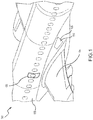
FIG. 1 illustrates a perspective view of an evacuation assembly of an aircraft, in accordance with various embodiments; -
FIGS. 2A, 2B, 2C, and 2D illustrate schematic cross-sectional views of an evacuation slide, in accordance with various embodiments; -
FIGS. 3A and 3B illustrate schematic cross-sectional views of an evacuation slide, in accordance with various embodiments; -
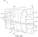
FIG. 4A illustrates a bottom perspective view of an evacuation slide, in accordance with various embodiments; -
FIG. 4B illustrates a side perspective view of the evacuation slide ofFIG. 4A , in accordance with various embodiments; -
FIGS. 5 and6 illustrate schematic perspective views of an evacuation slide having a plurality of cells, in accordance with various embodiments; and -
FIG. 7 is a schematic flow chart diagram of a method of manufacturing an evacuation slide of an evacuation assembly, in accordance with various embodiments. - The subject matter of the present disclosure is particularly pointed out and distinctly claimed in the concluding portion of the specification. A more complete understanding of the present disclosure, however, may best be obtained by referring to the detailed description and claims when considered in connection with the drawing figures, wherein like numerals denote like elements.
- The detailed description of exemplary embodiments herein makes reference to the accompanying drawings, which show exemplary embodiments by way of illustration. While these exemplary embodiments are described in sufficient detail to enable those skilled in the art to practice the disclosures, it should be understood that other embodiments may be realized and that logical changes and adaptations in design and construction may be made in accordance with this disclosure and the teachings herein. Thus, the detailed description herein is presented for purposes of illustration only and not of limitation. Throughout the present disclosure, like reference numbers denote like elements. Accordingly, elements with like element numbering may be shown in the figures but may not be necessarily be repeated herein for the sake of clarity.
- A first component that is "axially outward" of a second component means that a first component is positioned at a greater distance in either longitudinal direction away from the longitudinal center of the composite component along its longitudinal axis than the second component. A first component that is "axially inward" of a second component means that the first component is positioned closer to the longitudinal center of the composite component along its longitudinal axis than the second component.
- As used herein, "aft" refers to the direction associated with the tail (e.g., the back end) of an aircraft, or generally, to the direction of exhaust of the gas turbine. As used herein, "forward" refers to the direction associated with the nose (e.g., the front end) of an aircraft, or generally, to the direction of flight or motion.
- Referring to
FIG. 1 , anexemplary aircraft 100 is shown, in accordance with various embodiments.Aircraft 100 may comprise afuselage 102 withwings 104 fixed tofuselage 102.Emergency exit door 106 may be disposed on fuselage overwing 104 such that passengers exitingemergency exit door 106 would exit ontowing 104. Anevacuation slide assembly 108 may be disposed aft ofemergency exit door 106.Blowout panel 110 may coverevacuation slide assembly 108 when installed on theaircraft 100. In various embodiments, theevacuation slide assembly 108 may include and/or be housed within a packboard mounted to theaircraft 100. - The
evacuation slide assembly 108 may jettison theblowout panel 110 and deploy an evacuation slide, such as an inflatable evacuation slide, in response toemergency exit door 106 opening or in response to another evacuation event. As noted above, conventional evacuation slides are often subject to "kiting" under high wind conditions, rendering such slides less usable. - Accordingly, the present disclosure provides an evacuation slide of an aircraft evacuation assembly that has a top surface that has a top perimetrical length that is less than a bottom perimetrical length of a bottom surface of the evacuation slide. In other words, and according to various embodiments, the top flow path (i.e., the top perimetrical length) of wind across the top surface of the evacuation slide in a width direction, which is generally perpendicular to the longitudinal axis of the evacuation slide, is shorter than the bottom flow path (i.e., the bottom perimetrical length) of wind across the bottom surface. Said differently, the term '"perimetrical length" refers to the length of the air flow path across either a top or a bottom surface of the evacuation slide. Accordingly, the velocity of the wind flowing across the top surface (e.g., along the top perimetrical length) is less than the velocity of the wind flowing across the bottom surface (e.g., along the bottom perimetrical length), and such a velocity difference creates a pressure differential, per Bernoulli's principle, that produces a downward force on the evacuation slide. Thus, the inverted airfoil-like shape/geometry of the evacuation slide in a deployed state generally creates negative lift in windy conditions, thereby mitigating the "kiting" effect described above. As used herein, the term "airfoil-like" generally refers to a shape that has a leading edge, a trailing edge, a pressure surface extending between the leading edge and the trailing edge, and a suction surface extending between the leading edge and the trailing edge, wherein the arc length of the pressure surface (e.g., the top perimetrical length) is less than the arc length of the suction surface (e.g., the bottom perimetrical length).
- In various embodiments, and with momentary reference to
FIGS. 4A and4B , theevacuation slide 420 has ahead portion 421 that is configured to be coupled or mounted to theaircraft 100 and atoe portion 422 that is configured to engage the ground in a deployed state. In various embodiments, theevacuation slide 420 has the inverted airfoil-like configuration at least at thetoe portion 422 of theslide 420, but theevacuation slide 420 may have the inverted airfoil-like configuration along the entire longitudinal length of the evacuation slide 420 (e.g., from thehead portion 421 to the toe portion 422). - In various embodiments, and with reference to
FIGS. 2A, 2B, 2C, and 2D , the evacuation slide may be aninflatable evacuation slide support tube inflatable evacuation slide inflatable evacuation slide support tube chord surface support tube inflatable evacuation slide arc surface support tube inflatable evacuation slide - In various embodiments, the longitudinally extending
support tube pressure surface support tube inflatable evacuation slide suction surface support tube inflatable evacuation slide FIGS. 2C and 2D , the longitudinally extendingsupport tube more ties more ties support tube pressure surface 233D and thesuction surface 234D. - In various embodiments, and with reference to
FIGS. 5 and6 , the longitudinally extendingsupport tube inflatable evacuation slide inflatable evacuation slide cells support tube FIG. 5 , the plurality ofcells 536 may extend parallel to the longitudinal axis of the inflatable evacuation slide 520 (e.g., the plurality ofcells 536 may extend from the head portion to thetoe portion 522 of the inflatable evacuation slide 520). In various embodiments, and with reference toFIG. 6 , the plurality ofcells 636 may extend in the width direction (e.g., perpendicular to the longitudinal axis of the inflatable evacuation slide 620). - In various embodiments, and with reference to
FIGS. 3A and 3B , theinflatable evacuation slide border support tubes inflatable evacuation slide surface border support tubes surface top surface inflatable evacuation slide - The longitudinally extending
support tube surface FIG. 3A , the longitudinally extendingsupport tube 330A may be coupled to a lower side of the slidingsurface 327A, which may impart the airfoil-like shape/geometry to theinflatable evacuation slide 320A. In various embodiments, and with reference toFIG. 3B , the longitudinally extendingsupport tube 330B may form a middle divider disposed between the two longitudinally extendingborder support tubes 340B and thus may iviede the slidingsurface 327B into two passenger sliding lanes. In various embodiments, the longitudinally extendingsupport tube 330B has a larger diameter than the two longitudinally extendingborder support tubes 340B, which may impart the airfoil-like shape/geometry to theinflatable evacuation slide 320B. - In various embodiments, the
inflatable evacuation slide sheet support tube border support tubes sheet bottom surface inflatable evacuation slide sheet bottom surface inflatable evacuation slide inflatable evacuation slide - In various embodiments, and with reference to
FIGS. 4A and4B , theinflatable evacuation slide 420 includes one or moretransverse support tubes 439 that extend in the width direction and that form at least a portion of thebottom surface 424 of theinflatable evacuation slide 420.FIG. 4B shows the sheet removed in order to show the relative size between the longitudinally extendingsupport tube 430 and the two longitudinally extendingborder support tubes 440. Thesheet 428 may be coupled to and/or may extend over/across thetransverse support tubes 439. In various embodiments, theinflatable evacuation slide 420 may include various other features, such asauxiliary strap 429 which may extend along the longitudinally extendingsupport tube 430 to provide further stabilization to theinflatable evacuation slide 420. The slidingsurface 427 of theinflatable evacuation slide 420 may form at least a portion of thetop surface 423 of theinflatable evacuation slide 420. - In various embodiments, and with reference to
FIG. 7 , amethod 790 of manufacturing an evacuation slide of an aircraft evacuation assembly is provided. Themethod 790 may include coupling a sliding surface between two longitudinally extending border support tubes atstep 792 and coupling a longitudinally extending support tube to the sliding surface between the two longitudinally extending border support tubes atstep 794. Step 792 may form at least a portion of a top surface of the evacuation slide. Also, the longitudinally extending support tube disposed between the two longitudinally extending border support tubes may have a larger cross-sectional diameter than the two longitudinally extending border support tubes. Themethod 790 may further include coupling a sheet to the two longitudinally extending border support tubes and to the longitudinally extending support tube atstep 796. Step 796 form at least a portion of a bottom surface of the evacuation slide. In various embodiments, a top perimetrical length of the top surface of at least a toe portion of the evacuation slide in a width direction perpendicular to a longitudinal axis of the evacuation slide is less than a bottom perimetrical length of the bottom surface of the toe portion of the evacuation slide in the width direction. - Benefits, other advantages, and solutions to problems have been described herein with regard to specific embodiments. Furthermore, the connecting lines shown in the various figures contained herein are intended to represent exemplary functional relationships and/or physical couplings between the various elements. It should be noted that many alternative or additional functional relationships or physical connections may be present in a practical system. However, the benefits, advantages, solutions to problems, and any elements that may cause any benefit, advantage, or solution to occur or become more pronounced are not to be construed as critical, required, or essential features or elements of the disclosure.
- The scope of the disclosure is accordingly to be limited by nothing other than the appended claims, in which reference to an element in the singular is not intended to mean "one and only one" unless explicitly so stated, but rather "one or more." It is to be understood that unless specifically stated otherwise, references to "a," "an," and/or "the" may include one or more than one and that reference to an item in the singular may also include the item in the plural. All ranges and ratio limits disclosed herein may be combined.
- Moreover, where a phrase similar to "at least one of A, B, and C" is used in the claims, it is intended that the phrase be interpreted to mean that A alone may be present in an embodiment, B alone may be present in an embodiment, C alone may be present in an embodiment, or that any combination of the elements A, B and C may be present in a single embodiment; for example, A and B, A and C, B and C, or A and B and C. Different cross-hatching is used throughout the figures to denote different parts but not necessarily to denote the same or different materials.
- The steps recited in any of the method or process descriptions may be executed in any order and are not necessarily limited to the order presented. Furthermore, any reference to singular includes plural embodiments, and any reference to more than one component or step may include a singular embodiment or step. Elements and steps in the figures are illustrated for simplicity and clarity and have not necessarily been rendered according to any particular sequence. For example, steps that may be performed concurrently or in different order are illustrated in the figures to help to improve understanding of embodiments of the present disclosure.
- Any reference to attached, fixed, connected or the like may include permanent, removable, temporary, partial, full and/or any other possible attachment option. Additionally, any reference to without contact (or similar phrases) may also include reduced contact or minimal contact. Surface shading lines may be used throughout the figures to denote different parts or areas but not necessarily to denote the same or different materials. In some cases, reference coordinates may be specific to each figure.
- Systems, methods and apparatus are provided herein. In the detailed description herein, references to "one embodiment", "an embodiment", "various embodiments", etc., indicate that the embodiment described may include a particular feature, structure, or characteristic, but every embodiment may not necessarily include the particular feature, structure, or characteristic. Moreover, such phrases are not necessarily referring to the same embodiment. Further, when a particular feature, structure, or characteristic is described in connection with an embodiment, it is submitted that it is within the knowledge of one skilled in the art to affect such feature, structure, or characteristic in connection with other embodiments whether or not explicitly described. After reading the description, it will be apparent to one skilled in the relevant art(s) how to implement the disclosure in alternative embodiments.
Claims (15)
- An evacuation assembly of an aircraft, the evacuation assembly comprising:an evacuation slide being shaped and configured to produce negative lift in response to air flowing across the evacuation slide in a width direction, wherein the width direction is perpendicular to a longitudinal axis of the evacuation slide.
- The evacuation assembly of claim 1, wherein the evacuation slide comprises a head portion (421), a toe portion (422), a top surface (323), and a bottom surface (324), wherein the longitudinal axis extends centrally along a length of the evacuation slide from the head portion to the toe portion, wherein a top perimetrical length of the top surface of the toe portion of the evacuation slide in the width direction is less than a bottom perimetrical length of the bottom surface of the toe portion of the evacuation slide in the width direction.
- The evacuation assembly of claim 2, wherein the inflatable evacuation slide comprises a longitudinally extending support tube (230A, 230C) having a hemi-circular cross-sectional shape, wherein a chord surface (233C, 233D of the longitudinally extending support tube forms at least a portion of the top surface of the inflatable evacuation slide and an arc surface of the longitudinally extending support tube forms at least a portion of the bottom surface of the inflatable evacuation slide; or wherein the inflatable evacuation slide comprises a longitudinally extending support tube (230B, 230D) having an airfoil cross-sectional shape, wherein the airfoil cross-sectional shape has a leading edge, a trailing edge, a pressure surface extending between the leading edge and the trailing edge, and a suction surface extending between the leading edge and the trailing edge, wherein the pressure surface forms at least a portion of the top surface of the inflatable evacuation slide and the suction surface forms at least a portion of the bottom surface of the inflatable evacuation slide.
- The evacuation assembly of claim 3, wherein the longitudinally extending support tube comprises ties (235C, 235D) that impart the airfoil cross-sectional shape, and preferably wherein the ties are disposed internally within the longitudinally extending support tube and extend between the pressure surface and the suction surface; or wherein the longitudinally extending support tube comprises a plurality of cells (536) that impart the airfoil cross-sectional shape, and preferably wherein the plurality of cells extend in the width direction, or wherein the plurality of cells extend parallel to the longitudinal axis of the evacuation slide.
- The evacuation assembly of claim 2, wherein the inflatable evacuation slide comprises a sliding surface (327A, 327B) that forms at least a portion of the top surface of the inflatable evacuation slide.
- The evacuation assembly of claim 5, wherein the inflatable evacuation slide comprises a longitudinally extending support tube that is configured to support the sliding surface.
- The evacuation assembly of claim 6, wherein the inflatable evacuation slide comprises two longitudinally extending border support tubes (440) that extend parallel to the longitudinal axis, wherein the sliding surface is laterally bordered by and disposed between the two longitudinally extending border support tubes.
- The evacuation assembly of claim 7, wherein the longitudinally extending support tube is coupled to a lower side of the sliding surface.
- The evacuation assembly of claim 8, wherein the longitudinally extending support tube has a larger diameter than the two longitudinally extending border support tubes.
- The evacuation assembly of claim 8, wherein the evacuation assembly further comprises a sheet coupled to and extending between lower portions of the longitudinally extending support tube and the two longitudinally extending border support tubes, wherein the sheet forms at least a portion of the bottom surface of the inflatable evacuation slide.
- The evacuation assembly of claim 7, wherein the longitudinally extending support tube forms a middle divider between the two longitudinally extending border support tubes and divides the sliding surface into two lanes.
- The evacuation assembly of claim 11, wherein the evacuation assembly further comprises a sheet coupled to and extending between lower portions of the longitudinally extending support tube and the two longitudinally extending border support tubes, wherein the sheet forms at least a portion of the bottom surface of the inflatable evacuation slide.
- The evacuation assembly of claim 7, wherein the inflatable evacuation slide further comprises a transverse support tube that extends in the width direction and that forms at least a portion of the bottom surface of the inflatable evacuation slide.
- An evacuation assembly of an aircraft, the evacuation assembly comprising:an inflatable evacuation slide comprising a longitudinally extending support tube, two longitudinally extending border support tubes, a head portion, a toe portion, a longitudinal axis, a top surface, and a bottom surface, wherein the longitudinal axis extends centrally along a length of the evacuation slide from the head portion to the toe portion, wherein a top perimetrical length of the top surface of the toe portion of the inflatable evacuation slide in a width direction that is perpendicular to the longitudinal axis is less than a bottom perimetrical length of the bottom surface of the toe portion of the inflatable evacuation slide in the width direction;a sliding surface coupled to the longitudinally extending support tube and the two longitudinally extending border support tubes, wherein the two longitudinally extending border support tubes extend parallel to the longitudinal axis and wherein the sliding surface forms at least a portion of the top surface of at least the toe portion of the inflatable evacuation slide; anda sheet coupled to the longitudinally extending support tube and the two longitudinally extending border support tubes, wherein the sheet forms at least a portion of the bottom surface of at least the toe portion of the inflatable evacuation slide.
- A method of manufacturing an evacuation slide of an evacuation assembly of an aircraft, the method comprising:coupling a sliding surface between two longitudinally extending border support tubes to form at least a portion of a top surface of the evacuation slide;coupling a longitudinally extending support tube to the sliding surface between the two longitudinally extending border support tubes, wherein the longitudinally extending support tube has a larger cross-sectional diameter than the two longitudinally extending border support tubes; andcoupling a sheet to the two longitudinally extending border support tubes and to the longitudinally extending support tube to form at least a portion of a bottom surface of the evacuation slide;wherein a top perimetrical length of the top surface of at least a toe portion of the evacuation slide in a width direction perpendicular to a longitudinal axis of the evacuation slide is less than a bottom perimetrical length of the bottom surface of the toe portion of the evacuation slide in the width direction.
Applications Claiming Priority (1)
| Application Number | Priority Date | Filing Date | Title |
|---|---|---|---|
| US15/400,757 US10464682B2 (en) | 2017-01-06 | 2017-01-06 | Negative lift evacuation slide |
Publications (2)
| Publication Number | Publication Date |
|---|---|
| EP3345836A1 true EP3345836A1 (en) | 2018-07-11 |
| EP3345836B1 EP3345836B1 (en) | 2019-11-13 |
Family
ID=60935744
Family Applications (1)
| Application Number | Title | Priority Date | Filing Date |
|---|---|---|---|
| EP18150454.9A Active EP3345836B1 (en) | 2017-01-06 | 2018-01-05 | Negative lift evacuation slide |
Country Status (2)
| Country | Link |
|---|---|
| US (1) | US10464682B2 (en) |
| EP (1) | EP3345836B1 (en) |
Families Citing this family (3)
| Publication number | Priority date | Publication date | Assignee | Title |
|---|---|---|---|---|
| US10654574B2 (en) * | 2017-03-03 | 2020-05-19 | Goodrich Corporation | Airfoil for steadying an evacuation slide |
| US10647437B2 (en) | 2017-09-25 | 2020-05-12 | Goodrich Corporation | Continuously tensioned truss strap |
| US10640220B2 (en) * | 2017-10-24 | 2020-05-05 | Goodrich Corporation | Anti-kiting device |
Citations (4)
| Publication number | Priority date | Publication date | Assignee | Title |
|---|---|---|---|---|
| US3370684A (en) * | 1966-09-08 | 1968-02-27 | Ind Covers Inc | Inflatable escape slide |
| US4434870A (en) * | 1982-11-22 | 1984-03-06 | The B. F. Goodrich Company | Evacuation slide device |
| EP0383033A1 (en) * | 1989-02-16 | 1990-08-22 | PIRELLI S.p.A. | Emergency device to allow a number of people to be transferred between two areas far apart from each other |
| EP1431178A1 (en) * | 2002-12-19 | 2004-06-23 | Goodrich Corporation | Evacuation slide with leading edge spoiler |
Family Cites Families (6)
| Publication number | Priority date | Publication date | Assignee | Title |
|---|---|---|---|---|
| US3860984A (en) * | 1973-06-25 | 1975-01-21 | Goodrich Co B F | Inflatable life raft escape slide |
| US4332049A (en) * | 1980-02-19 | 1982-06-01 | The B. F. Goodrich Company | Escape slide and protective shield |
| US6471001B1 (en) * | 1999-10-06 | 2002-10-29 | The B.F. Goodrich Corporation | Escape slide |
| US6298970B1 (en) * | 2000-05-17 | 2001-10-09 | Air Cruisers Company | Inflatable evacuation slide with adjustable decelerator |
| US6799741B2 (en) * | 2002-06-21 | 2004-10-05 | Goodrich Corporation | Evacuation slide having trapezoidal outline |
| US9162735B2 (en) * | 2008-08-28 | 2015-10-20 | Michael Grainger | Inflatable evacuation slide |
-
2017
- 2017-01-06 US US15/400,757 patent/US10464682B2/en active Active
-
2018
- 2018-01-05 EP EP18150454.9A patent/EP3345836B1/en active Active
Patent Citations (4)
| Publication number | Priority date | Publication date | Assignee | Title |
|---|---|---|---|---|
| US3370684A (en) * | 1966-09-08 | 1968-02-27 | Ind Covers Inc | Inflatable escape slide |
| US4434870A (en) * | 1982-11-22 | 1984-03-06 | The B. F. Goodrich Company | Evacuation slide device |
| EP0383033A1 (en) * | 1989-02-16 | 1990-08-22 | PIRELLI S.p.A. | Emergency device to allow a number of people to be transferred between two areas far apart from each other |
| EP1431178A1 (en) * | 2002-12-19 | 2004-06-23 | Goodrich Corporation | Evacuation slide with leading edge spoiler |
Also Published As
| Publication number | Publication date |
|---|---|
| US10464682B2 (en) | 2019-11-05 |
| BR102017023541A2 (en) | 2018-07-24 |
| EP3345836B1 (en) | 2019-11-13 |
| US20180194482A1 (en) | 2018-07-12 |
Similar Documents
| Publication | Publication Date | Title |
|---|---|---|
| US20110260008A1 (en) | Fluid flow control device for an aerofoil | |
| US9555895B2 (en) | Motor pylons for a kite and airborne power generation system using same | |
| US10144499B2 (en) | Aerofoil accessories and method for modifying the geometry of a wing element | |
| US20150191244A1 (en) | Aircraft wing with system establishing a laminar boundary layer flow | |
| EP3345836B1 (en) | Negative lift evacuation slide | |
| US10730605B2 (en) | Aircraft joint | |
| US10196129B2 (en) | Aerofoil and wings for air vehicles | |
| US6905092B2 (en) | Laminar-flow airfoil | |
| US20170327202A1 (en) | Aircraft joint | |
| US7614588B2 (en) | Apparatus system and method for drag reduction | |
| CN111137434B (en) | Wings and related methods, aircraft, and aerodynamic structures and devices | |
| US8573542B2 (en) | Aerofoil slot blowing | |
| EP0052360B1 (en) | Air aspiration device of aircraft-mounted gas-turbine engine | |
| EP3378777B1 (en) | Dual configuration evacuation assembly | |
| EP3750796A1 (en) | Wing assembly with slats and aircraft | |
| US12371192B2 (en) | Method for mounting a vortex generator on a curved aerodynamic panel of an aircraft and aircraft comprising at least one vortex generator mounted in this way | |
| BR102017023541B1 (en) | ASSEMBLY FOR EVACUATION OF AN AIRCRAFT, AND METHOD FOR PRODUCING AN EVACUATION SLIDER | |
| EP4644234A1 (en) | Leading edge movable device of an aircraft wing | |
| US20240109648A1 (en) | Aircraft portion with a reduced drag | |
| IL226119A (en) | Aerofoil, wings and air vehicles | |
| Keener | Professional Measurements Obtained in Flight at Transonic Speeds for a Conically Cambered Delta Wing | |
| IL194156A (en) | Aerofoil accessories |
Legal Events
| Date | Code | Title | Description |
|---|---|---|---|
| PUAI | Public reference made under article 153(3) epc to a published international application that has entered the european phase |
Free format text: ORIGINAL CODE: 0009012 |
|
| STAA | Information on the status of an ep patent application or granted ep patent |
Free format text: STATUS: THE APPLICATION HAS BEEN PUBLISHED |
|
| AK | Designated contracting states |
Kind code of ref document: A1 Designated state(s): AL AT BE BG CH CY CZ DE DK EE ES FI FR GB GR HR HU IE IS IT LI LT LU LV MC MK MT NL NO PL PT RO RS SE SI SK SM TR |
|
| AX | Request for extension of the european patent |
Extension state: BA ME |
|
| STAA | Information on the status of an ep patent application or granted ep patent |
Free format text: STATUS: REQUEST FOR EXAMINATION WAS MADE |
|
| 17P | Request for examination filed |
Effective date: 20190111 |
|
| RBV | Designated contracting states (corrected) |
Designated state(s): AL AT BE BG CH CY CZ DE DK EE ES FI FR GB GR HR HU IE IS IT LI LT LU LV MC MK MT NL NO PL PT RO RS SE SI SK SM TR |
|
| GRAP | Despatch of communication of intention to grant a patent |
Free format text: ORIGINAL CODE: EPIDOSNIGR1 |
|
| STAA | Information on the status of an ep patent application or granted ep patent |
Free format text: STATUS: GRANT OF PATENT IS INTENDED |
|
| INTG | Intention to grant announced |
Effective date: 20190612 |
|
| GRAS | Grant fee paid |
Free format text: ORIGINAL CODE: EPIDOSNIGR3 |
|
| GRAA | (expected) grant |
Free format text: ORIGINAL CODE: 0009210 |
|
| STAA | Information on the status of an ep patent application or granted ep patent |
Free format text: STATUS: THE PATENT HAS BEEN GRANTED |
|
| AK | Designated contracting states |
Kind code of ref document: B1 Designated state(s): AL AT BE BG CH CY CZ DE DK EE ES FI FR GB GR HR HU IE IS IT LI LT LU LV MC MK MT NL NO PL PT RO RS SE SI SK SM TR |
|
| REG | Reference to a national code |
Ref country code: CH Ref legal event code: EP Ref country code: AT Ref legal event code: REF Ref document number: 1201414 Country of ref document: AT Kind code of ref document: T Effective date: 20191115 |
|
| REG | Reference to a national code |
Ref country code: DE Ref legal event code: R096 Ref document number: 602018001112 Country of ref document: DE |
|
| REG | Reference to a national code |
Ref country code: IE Ref legal event code: FG4D |
|
| REG | Reference to a national code |
Ref country code: NL Ref legal event code: MP Effective date: 20191113 |
|
| REG | Reference to a national code |
Ref country code: LT Ref legal event code: MG4D |
|
| PG25 | Lapsed in a contracting state [announced via postgrant information from national office to epo] |
Ref country code: BG Free format text: LAPSE BECAUSE OF FAILURE TO SUBMIT A TRANSLATION OF THE DESCRIPTION OR TO PAY THE FEE WITHIN THE PRESCRIBED TIME-LIMIT Effective date: 20200213 Ref country code: LT Free format text: LAPSE BECAUSE OF FAILURE TO SUBMIT A TRANSLATION OF THE DESCRIPTION OR TO PAY THE FEE WITHIN THE PRESCRIBED TIME-LIMIT Effective date: 20191113 Ref country code: FI Free format text: LAPSE BECAUSE OF FAILURE TO SUBMIT A TRANSLATION OF THE DESCRIPTION OR TO PAY THE FEE WITHIN THE PRESCRIBED TIME-LIMIT Effective date: 20191113 Ref country code: SE Free format text: LAPSE BECAUSE OF FAILURE TO SUBMIT A TRANSLATION OF THE DESCRIPTION OR TO PAY THE FEE WITHIN THE PRESCRIBED TIME-LIMIT Effective date: 20191113 Ref country code: LV Free format text: LAPSE BECAUSE OF FAILURE TO SUBMIT A TRANSLATION OF THE DESCRIPTION OR TO PAY THE FEE WITHIN THE PRESCRIBED TIME-LIMIT Effective date: 20191113 Ref country code: NO Free format text: LAPSE BECAUSE OF FAILURE TO SUBMIT A TRANSLATION OF THE DESCRIPTION OR TO PAY THE FEE WITHIN THE PRESCRIBED TIME-LIMIT Effective date: 20200213 Ref country code: GR Free format text: LAPSE BECAUSE OF FAILURE TO SUBMIT A TRANSLATION OF THE DESCRIPTION OR TO PAY THE FEE WITHIN THE PRESCRIBED TIME-LIMIT Effective date: 20200214 Ref country code: PL Free format text: LAPSE BECAUSE OF FAILURE TO SUBMIT A TRANSLATION OF THE DESCRIPTION OR TO PAY THE FEE WITHIN THE PRESCRIBED TIME-LIMIT Effective date: 20191113 Ref country code: PT Free format text: LAPSE BECAUSE OF FAILURE TO SUBMIT A TRANSLATION OF THE DESCRIPTION OR TO PAY THE FEE WITHIN THE PRESCRIBED TIME-LIMIT Effective date: 20200313 Ref country code: NL Free format text: LAPSE BECAUSE OF FAILURE TO SUBMIT A TRANSLATION OF THE DESCRIPTION OR TO PAY THE FEE WITHIN THE PRESCRIBED TIME-LIMIT Effective date: 20191113 |
|
| PG25 | Lapsed in a contracting state [announced via postgrant information from national office to epo] |
Ref country code: IS Free format text: LAPSE BECAUSE OF FAILURE TO SUBMIT A TRANSLATION OF THE DESCRIPTION OR TO PAY THE FEE WITHIN THE PRESCRIBED TIME-LIMIT Effective date: 20200313 Ref country code: RS Free format text: LAPSE BECAUSE OF FAILURE TO SUBMIT A TRANSLATION OF THE DESCRIPTION OR TO PAY THE FEE WITHIN THE PRESCRIBED TIME-LIMIT Effective date: 20191113 Ref country code: HR Free format text: LAPSE BECAUSE OF FAILURE TO SUBMIT A TRANSLATION OF THE DESCRIPTION OR TO PAY THE FEE WITHIN THE PRESCRIBED TIME-LIMIT Effective date: 20191113 |
|
| PG25 | Lapsed in a contracting state [announced via postgrant information from national office to epo] |
Ref country code: AL Free format text: LAPSE BECAUSE OF FAILURE TO SUBMIT A TRANSLATION OF THE DESCRIPTION OR TO PAY THE FEE WITHIN THE PRESCRIBED TIME-LIMIT Effective date: 20191113 |
|
| PG25 | Lapsed in a contracting state [announced via postgrant information from national office to epo] |
Ref country code: ES Free format text: LAPSE BECAUSE OF FAILURE TO SUBMIT A TRANSLATION OF THE DESCRIPTION OR TO PAY THE FEE WITHIN THE PRESCRIBED TIME-LIMIT Effective date: 20191113 Ref country code: EE Free format text: LAPSE BECAUSE OF FAILURE TO SUBMIT A TRANSLATION OF THE DESCRIPTION OR TO PAY THE FEE WITHIN THE PRESCRIBED TIME-LIMIT Effective date: 20191113 Ref country code: DK Free format text: LAPSE BECAUSE OF FAILURE TO SUBMIT A TRANSLATION OF THE DESCRIPTION OR TO PAY THE FEE WITHIN THE PRESCRIBED TIME-LIMIT Effective date: 20191113 Ref country code: RO Free format text: LAPSE BECAUSE OF FAILURE TO SUBMIT A TRANSLATION OF THE DESCRIPTION OR TO PAY THE FEE WITHIN THE PRESCRIBED TIME-LIMIT Effective date: 20191113 Ref country code: CZ Free format text: LAPSE BECAUSE OF FAILURE TO SUBMIT A TRANSLATION OF THE DESCRIPTION OR TO PAY THE FEE WITHIN THE PRESCRIBED TIME-LIMIT Effective date: 20191113 |
|
| REG | Reference to a national code |
Ref country code: DE Ref legal event code: R097 Ref document number: 602018001112 Country of ref document: DE |
|
| REG | Reference to a national code |
Ref country code: AT Ref legal event code: MK05 Ref document number: 1201414 Country of ref document: AT Kind code of ref document: T Effective date: 20191113 |
|
| PG25 | Lapsed in a contracting state [announced via postgrant information from national office to epo] |
Ref country code: MC Free format text: LAPSE BECAUSE OF FAILURE TO SUBMIT A TRANSLATION OF THE DESCRIPTION OR TO PAY THE FEE WITHIN THE PRESCRIBED TIME-LIMIT Effective date: 20191113 Ref country code: SM Free format text: LAPSE BECAUSE OF FAILURE TO SUBMIT A TRANSLATION OF THE DESCRIPTION OR TO PAY THE FEE WITHIN THE PRESCRIBED TIME-LIMIT Effective date: 20191113 Ref country code: SK Free format text: LAPSE BECAUSE OF FAILURE TO SUBMIT A TRANSLATION OF THE DESCRIPTION OR TO PAY THE FEE WITHIN THE PRESCRIBED TIME-LIMIT Effective date: 20191113 |
|
| PLBE | No opposition filed within time limit |
Free format text: ORIGINAL CODE: 0009261 |
|
| STAA | Information on the status of an ep patent application or granted ep patent |
Free format text: STATUS: NO OPPOSITION FILED WITHIN TIME LIMIT |
|
| REG | Reference to a national code |
Ref country code: BE Ref legal event code: MM Effective date: 20200131 |
|
| 26N | No opposition filed |
Effective date: 20200814 |
|
| PG25 | Lapsed in a contracting state [announced via postgrant information from national office to epo] |
Ref country code: LU Free format text: LAPSE BECAUSE OF NON-PAYMENT OF DUE FEES Effective date: 20200105 |
|
| PG25 | Lapsed in a contracting state [announced via postgrant information from national office to epo] |
Ref country code: AT Free format text: LAPSE BECAUSE OF FAILURE TO SUBMIT A TRANSLATION OF THE DESCRIPTION OR TO PAY THE FEE WITHIN THE PRESCRIBED TIME-LIMIT Effective date: 20191113 Ref country code: BE Free format text: LAPSE BECAUSE OF NON-PAYMENT OF DUE FEES Effective date: 20200131 Ref country code: SI Free format text: LAPSE BECAUSE OF FAILURE TO SUBMIT A TRANSLATION OF THE DESCRIPTION OR TO PAY THE FEE WITHIN THE PRESCRIBED TIME-LIMIT Effective date: 20191113 |
|
| PG25 | Lapsed in a contracting state [announced via postgrant information from national office to epo] |
Ref country code: IE Free format text: LAPSE BECAUSE OF NON-PAYMENT OF DUE FEES Effective date: 20200105 Ref country code: IT Free format text: LAPSE BECAUSE OF FAILURE TO SUBMIT A TRANSLATION OF THE DESCRIPTION OR TO PAY THE FEE WITHIN THE PRESCRIBED TIME-LIMIT Effective date: 20191113 |
|
| REG | Reference to a national code |
Ref country code: CH Ref legal event code: PL |
|
| PG25 | Lapsed in a contracting state [announced via postgrant information from national office to epo] |
Ref country code: CH Free format text: LAPSE BECAUSE OF NON-PAYMENT OF DUE FEES Effective date: 20210131 Ref country code: LI Free format text: LAPSE BECAUSE OF NON-PAYMENT OF DUE FEES Effective date: 20210131 |
|
| PG25 | Lapsed in a contracting state [announced via postgrant information from national office to epo] |
Ref country code: TR Free format text: LAPSE BECAUSE OF FAILURE TO SUBMIT A TRANSLATION OF THE DESCRIPTION OR TO PAY THE FEE WITHIN THE PRESCRIBED TIME-LIMIT Effective date: 20191113 Ref country code: MT Free format text: LAPSE BECAUSE OF FAILURE TO SUBMIT A TRANSLATION OF THE DESCRIPTION OR TO PAY THE FEE WITHIN THE PRESCRIBED TIME-LIMIT Effective date: 20191113 Ref country code: CY Free format text: LAPSE BECAUSE OF FAILURE TO SUBMIT A TRANSLATION OF THE DESCRIPTION OR TO PAY THE FEE WITHIN THE PRESCRIBED TIME-LIMIT Effective date: 20191113 |
|
| PG25 | Lapsed in a contracting state [announced via postgrant information from national office to epo] |
Ref country code: MK Free format text: LAPSE BECAUSE OF FAILURE TO SUBMIT A TRANSLATION OF THE DESCRIPTION OR TO PAY THE FEE WITHIN THE PRESCRIBED TIME-LIMIT Effective date: 20191113 |
|
| P01 | Opt-out of the competence of the unified patent court (upc) registered |
Effective date: 20230522 |
|
| PGFP | Annual fee paid to national office [announced via postgrant information from national office to epo] |
Ref country code: GB Payment date: 20251219 Year of fee payment: 9 |
|
| PGFP | Annual fee paid to national office [announced via postgrant information from national office to epo] |
Ref country code: FR Payment date: 20251217 Year of fee payment: 9 |
|
| PGFP | Annual fee paid to national office [announced via postgrant information from national office to epo] |
Ref country code: DE Payment date: 20251217 Year of fee payment: 9 |