EP3345825A1 - Latch system with position hold - Google Patents
Latch system with position hold Download PDFInfo
- Publication number
- EP3345825A1 EP3345825A1 EP17154653.4A EP17154653A EP3345825A1 EP 3345825 A1 EP3345825 A1 EP 3345825A1 EP 17154653 A EP17154653 A EP 17154653A EP 3345825 A1 EP3345825 A1 EP 3345825A1
- Authority
- EP
- European Patent Office
- Prior art keywords
- control
- pin
- latch system
- hole
- wall
- Prior art date
- Legal status (The legal status is an assumption and is not a legal conclusion. Google has not performed a legal analysis and makes no representation as to the accuracy of the status listed.)
- Granted
Links
Images



Classifications
-
- B—PERFORMING OPERATIONS; TRANSPORTING
- B64—AIRCRAFT; AVIATION; COSMONAUTICS
- B64C—AEROPLANES; HELICOPTERS
- B64C1/00—Fuselages; Constructional features common to fuselages, wings, stabilising surfaces or the like
- B64C1/14—Windows; Doors; Hatch covers or access panels; Surrounding frame structures; Canopies; Windscreens accessories therefor, e.g. pressure sensors, water deflectors, hinges, seals, handles, latches, windscreen wipers
- B64C1/1407—Doors; surrounding frames
- B64C1/1423—Passenger doors
- B64C1/1438—Passenger doors of the sliding type
-
- E—FIXED CONSTRUCTIONS
- E05—LOCKS; KEYS; WINDOW OR DOOR FITTINGS; SAFES
- E05C—BOLTS OR FASTENING DEVICES FOR WINGS, SPECIALLY FOR DOORS OR WINDOWS
- E05C9/00—Arrangements of simultaneously actuated bolts or other securing devices at well-separated positions on the same wing
- E05C9/18—Details of fastening means or of fixed retaining means for the ends of bars
- E05C9/1825—Fastening means
- E05C9/1833—Fastening means performing sliding movements
- E05C9/1841—Fastening means performing sliding movements perpendicular to actuating bar
-
- B—PERFORMING OPERATIONS; TRANSPORTING
- B64—AIRCRAFT; AVIATION; COSMONAUTICS
- B64C—AEROPLANES; HELICOPTERS
- B64C1/00—Fuselages; Constructional features common to fuselages, wings, stabilising surfaces or the like
- B64C1/14—Windows; Doors; Hatch covers or access panels; Surrounding frame structures; Canopies; Windscreens accessories therefor, e.g. pressure sensors, water deflectors, hinges, seals, handles, latches, windscreen wipers
- B64C1/1407—Doors; surrounding frames
-
- B—PERFORMING OPERATIONS; TRANSPORTING
- B64—AIRCRAFT; AVIATION; COSMONAUTICS
- B64C—AEROPLANES; HELICOPTERS
- B64C27/00—Rotorcraft; Rotors peculiar thereto
- B64C27/04—Helicopters
-
- E—FIXED CONSTRUCTIONS
- E05—LOCKS; KEYS; WINDOW OR DOOR FITTINGS; SAFES
- E05B—LOCKS; ACCESSORIES THEREFOR; HANDCUFFS
- E05B17/00—Accessories in connection with locks
- E05B17/20—Means independent of the locking mechanism for preventing unauthorised opening, e.g. for securing the bolt in the fastening position
- E05B17/2007—Securing, deadlocking or "dogging" the bolt in the fastening position
-
- E—FIXED CONSTRUCTIONS
- E05—LOCKS; KEYS; WINDOW OR DOOR FITTINGS; SAFES
- E05B—LOCKS; ACCESSORIES THEREFOR; HANDCUFFS
- E05B17/00—Accessories in connection with locks
- E05B17/20—Means independent of the locking mechanism for preventing unauthorised opening, e.g. for securing the bolt in the fastening position
- E05B17/2007—Securing, deadlocking or "dogging" the bolt in the fastening position
- E05B17/2049—Securing, deadlocking or "dogging" the bolt in the fastening position following the movement of the bolt
- E05B17/2057—Securing, deadlocking or "dogging" the bolt in the fastening position following the movement of the bolt moving rectilinearly relating to the bolt
-
- E—FIXED CONSTRUCTIONS
- E05—LOCKS; KEYS; WINDOW OR DOOR FITTINGS; SAFES
- E05B—LOCKS; ACCESSORIES THEREFOR; HANDCUFFS
- E05B77/00—Vehicle locks characterised by special functions or purposes
- E05B77/14—Specially controlled locking actions in case of open doors or in case of doors moved from an open to a closed position, e.g. lock-out prevention or self-cancelling
- E05B77/16—Preventing locking with the bolt in the unlatched position, i.e. when the door is open
-
- E—FIXED CONSTRUCTIONS
- E05—LOCKS; KEYS; WINDOW OR DOOR FITTINGS; SAFES
- E05B—LOCKS; ACCESSORIES THEREFOR; HANDCUFFS
- E05B83/00—Vehicle locks specially adapted for particular types of wing or vehicle
- E05B83/36—Locks for passenger or like doors
- E05B83/38—Locks for passenger or like doors for pillar-less vehicles, i.e. vehicles where a front and a back door engage each other in the closed position
-
- E—FIXED CONSTRUCTIONS
- E05—LOCKS; KEYS; WINDOW OR DOOR FITTINGS; SAFES
- E05C—BOLTS OR FASTENING DEVICES FOR WINGS, SPECIALLY FOR DOORS OR WINDOWS
- E05C1/00—Fastening devices with bolts moving rectilinearly
- E05C1/02—Fastening devices with bolts moving rectilinearly without latching action
- E05C1/04—Fastening devices with bolts moving rectilinearly without latching action with operating handle or equivalent member rigid with the bolt
-
- E—FIXED CONSTRUCTIONS
- E05—LOCKS; KEYS; WINDOW OR DOOR FITTINGS; SAFES
- E05C—BOLTS OR FASTENING DEVICES FOR WINGS, SPECIALLY FOR DOORS OR WINDOWS
- E05C7/00—Fastening devices specially adapted for two wings
- E05C7/04—Fastening devices specially adapted for two wings for wings which abut when closed
- E05C7/045—Sliding bolts mounted on or in the edge of a normally closed wing of a double-door or -window
-
- E—FIXED CONSTRUCTIONS
- E05—LOCKS; KEYS; WINDOW OR DOOR FITTINGS; SAFES
- E05C—BOLTS OR FASTENING DEVICES FOR WINGS, SPECIALLY FOR DOORS OR WINDOWS
- E05C9/00—Arrangements of simultaneously actuated bolts or other securing devices at well-separated positions on the same wing
- E05C9/04—Arrangements of simultaneously actuated bolts or other securing devices at well-separated positions on the same wing with two sliding bars moved in opposite directions when fastening or unfastening
- E05C9/042—Arrangements of simultaneously actuated bolts or other securing devices at well-separated positions on the same wing with two sliding bars moved in opposite directions when fastening or unfastening with pins engaging slots
Definitions
- Vehicle door latch systems such as, but not limited to, door latch systems for helicopters and other aircraft comprise features configured to positively hold a latch in either a locked position or an unlocked position. It can be particularly important that door latch systems used with helicopters and other aircraft do not accidentally become unlatched so that doors do not open during flight unless intended to be opened. Some doors remaining closed is a safety of flight issue which requires latches that are fail-safe from inadvertently opening in flight. While some door latch systems utilize an overcenter feature to maintain a door latch in an open position or a closed position, some overcenter features require utilization of complicated, expensive, and/or heavy components or can inadvertently unlatch.
- Helicopter 100 can include a fuselage 102, a landing gear 104, a tail member 106, a main rotor system 108 comprising main rotor blades 110, and a tail rotor system 112 comprising tail rotor blades 114.
- the main rotor blades 110 and the tail rotor blades 114 can be rotated and selectively controlled in order to selectively control direction, thrust, and lift of helicopter 100.
- the helicopter 100 further comprises a fore right door 116, an aft right door 118, a fore left door 120, and an aft left door 122.
- the fore right door 116 and the fore left door 120 are attached to the fuselage 102 via fore hinges 124 which allow an aft portion of the fore right door 116 and an aft portion of the fore left door 120 to rotate away from the fuselage 102.
- the aft right door 118 and the aft left door 122 are attached to the fuselage 102 via aft hinges 126 which allow a fore portion of the aft right door 118 and a fore portion of the aft left door 122 to rotate away from the fuselage 102.
- each of the aft right door 118 and the aft left door 122 comprise a lip 128 against which an aft portion of the fore right door 116 and an aft portion of the fore left door 120 are configured to overlap.
- the helicopter 100 further comprises four latch systems 200.
- Each of the aft right door 118 and the aft left door 122 comprise door channels 130 adjacent the lip 128 and latch systems 200 are disposed in an upper portion of each door channel 130 and disposed in a lower portion of each door channel 130.
- the aft right door 118 and the aft left door 122 are substantially symmetrical or mirror images of each other. Although in this embodiment the aft right door 118 and the aft left door 122 are not identical, in some embodiments, the latch systems 200 carried by the aft right door 118 and the aft left door 122 are substantially the same, identical, and/or interchangeable.
- each latch system 200 comprises a housing 202 and a pin 204 that is carried by the housing 202 and movable relative to the housing 202.
- the housing 202 comprises a mount wall 206 connected to a control wall 208 that is substantially orthogonal relative to the mount wall 206.
- the housing 202 further comprises an inner wall 210 that is substantially orthogonal to each of the mount wall 206 and the control wall 208.
- the housing 202 comprises an outer wall 212 that is substantially parallel to the inner wall 210 and offset from the inner wall 210.
- Each of the mount wall 206 and the control wall 208 comprises apertures configured to receive fasteners 214 that are used to connect the housing 202 to the door channel 130.
- Each of the inner wall 210 and the outer wall 212 comprise coaxial apertures configured to receive an inner bushing 216 and an outer bushing 218, respectively.
- the inner bushing 216 and the outer bushing 218 comprise apertures configured to receive the pin 204 therethrough and configured to allow movement of the pin 204 along a pin axis 220 of the latch system 200.
- the pin 204 comprises an enlarged receiver 222 comprising an aperture through the receiver 222 and the aperture extends along a receiver axis 224.
- the mount wall 206 comprises a control aperture 226 through which a control rod 228 extends and is received within the aperture of the receiver 222 of the pin 204.
- an end portion of the control rod 228 may be threaded to complement threads of the aperture of the receiver 222.
- the control rod 228 further comprises a shelf 230 sized and configured to not be able to pass through the control aperture 226.
- the control rod 228 further carries a cap 232 comprising a larger outer diameter than the outer diameter of the control rod 228 that extends through the control aperture 226.
- the cap 232 can comprise an a threaded hole configured to receive a threaded end of the control rod 228.
- the latch system 200 comprises a control knob 236.
- the control knob 236 is a tubular member comprising several differentiated internal and external diameters so as to provide a cap space 238 through which the cap 232 can translate along the receiver axis 224, an intermediate space 240 that is too small in internal diameter to allow entry of the cap 232, and a rod space 242 that comprises an internal diameter substantially complementary to an outside diameter of the control rod 228.
- the spring 234 is wound around the control rod 228 and is compressed between the cap 232 and an interior wall 244 of the control knob 236 so that the control knob 236 is biased toward the pin 204.
- the control aperture 226 generally comprises a dog bone shaped channel comprising a lock hole 246 comprising an inner diameter substantially complementary to a lock tip 248 of the control knob 236.
- the control aperture 226 further comprises an unlock hole 250 comprising an inner diameter substantially complementary to the lock tip 248.
- the lock hole 246 and the unlock hole 250 are joined by a rod channel 252 that provides a gap distance large enough for the control rod 228 to extend through but too small for the lock tip 248 to fit into.
- the control aperture 226 can be countersunk using a recess 254 so that the lock tip 248 can be maintained within the recess 254 even while the lock tip 248 is not received within either of the lock hole 246 or the unlock hole 250.
- the latch system 200 can be checked to ensure that the latch system 200 pin 204 is in a locked position.
- the pin 204 is in a locked position when the lock tip 248 is received through the lock hole 246 until an end of the lock tip 248 abuts the shelf 230 of the control rod 228.
- the latch system 200 can be operated to move the pin 204 from the locked position to an unlocked position.
- the control knob 236 can be pulled away from the pin 204 along the receiver axis 224 and against the biasing force of the spring 234 until the lock tip 248 is fully removed from the lock hole 246.
- the control knob 236 can be moved closer to the inner wall 210 by sliding the control rod 228 through the rod channel 252 until the lock tip 248 is aligned with the unlock hole 250. During this movement of the control rod 228, the pin 204 will also move in the same direction along the pin axis 220, thereby retracting the pin 204 from the relatively more extended locked position. Once the lock tip 248 is aligned with the unlock hole 250, the control knob 236 can be released to allow the biasing of the spring 234 to move the lock tip 248 into the unlock hole 250. Once the end of the lock tip 248 abuts the shelf 230, the pin 204 is secured in the unlocked position. Of course, the pin 204 can be returned to the locked position by reversing the above-described steps.
- the latch system 200 can prevent accidental movement of the pin 204 from a locked position as well as from an unlocked position. In some cases, it is important to ensure the pin 204 remains in an unlocked position so that the aft left door 122 is not accidentally urged toward a closed position with the pin 204 protruding since doing so can cause damage to the helicopter 100 and/or the latch system 200. In other cases, it is important to ensure the pin 204 remains in a locked position so that the aft left door 122 does not undesirably open.
- the latch system 200 is primarily described above as being used with a helicopter 100, in alternative embodiments, the latch system 200 can be utilized in conjunction with any other device. Specifically, the latch system 200 can be incorporated into left doors, right doors, fore doors, aft doors, and doors of airplanes and/or any other vehicle. Still further, the latch system 200 can be utilized in other non-vehicle application while still providing the same ability to selectively secure a pin 204 in a desired position. While not shown, it will be appreciated that the helicopter 100 and/or any other system into which the latch system 200 is incorporated, can comprise a strike plate comprising a hole or any other suitable structure for receiving the pin 204 and securing a door relative to the structure.
- the latch system 200 is shown as being located in particular locations relative to a door, in alternative embodiments, the latch system 200 can be located at different locations. Still further, while the helicopter 100 is shown comprising four doors, an alternative embodiment of a helicopter comprising the latch system 200 can comprise a fore left door, an aft left door, and a fore right door without including an aft right door. In other alternative embodiments of a helicopter comprising the latch system 200, a helicopter can comprise only one door or two doors, such as, but not limited to comprising only a fore left door and a fore right door or only a fore left door or a fore right door. In other embodiments, the latch system 200 can be used on any one or more of an aft right door, aft left door, fore right door, and fore left door, and/or any other door carried by the helicopter.
- R l a numerical range with a lower limit, R l , and an upper limit, R u .
- R l any number falling within the range is specifically disclosed.
- any numerical range defined by two R numbers as defined in the above is also specifically disclosed.
Landscapes
- Engineering & Computer Science (AREA)
- Mechanical Engineering (AREA)
- Aviation & Aerospace Engineering (AREA)
- Lock And Its Accessories (AREA)
Abstract
Description
- Vehicle door latch systems, such as, but not limited to, door latch systems for helicopters and other aircraft comprise features configured to positively hold a latch in either a locked position or an unlocked position. It can be particularly important that door latch systems used with helicopters and other aircraft do not accidentally become unlatched so that doors do not open during flight unless intended to be opened. Some doors remaining closed is a safety of flight issue which requires latches that are fail-safe from inadvertently opening in flight. While some door latch systems utilize an overcenter feature to maintain a door latch in an open position or a closed position, some overcenter features require utilization of complicated, expensive, and/or heavy components or can inadvertently unlatch.
-
-
Figure 1 is an orthogonal left side view of a helicopter according to an embodiment of this disclosure. -
Figure 2 is an orthogonal top view of the aircraft ofFigure 1 . -
Figure 3 is a partial oblique left side view of the aircraft ofFigure 1 showing doors of the aircraft ofFigure 1 in greater detail. -
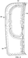
Figure 4 is an orthogonal right side view of an aft left door ofFigure 3 . -
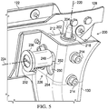
Figure 5 is an oblique rear-right view of a upper located latch system of the aft left door ofFigure 3 . -
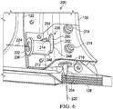
Figure 6 is an oblique rear-right view a lower located latch system of the aft left door ofFigure 3 . -
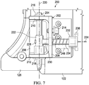
Figure 7 is an orthogonal side view of the lower located latch system ofFigure 6 . -
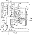
Figure 8 is an oblique cutaway view of the lower located latch system ofFigure 6 . -
Figure 9 is a rear-right oblique view of the lower located latch system ofFigure 6 . -
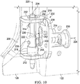
Figure 10 is a front-left oblique view of the lower located latch system ofFigure 6 . - In the specification, reference may be made to the spatial relationships between various components and to the spatial orientation of various aspects of components as the devices are depicted in the attached drawings. However, as will be recognized by those skilled in the art after a complete reading of the present disclosure, the devices, members, apparatuses, etc. described herein may be positioned in any desired orientation. Thus, the use of terms such as "above," "below," "upper," "lower," or other like terms to describe a spatial relationship between various components or to describe the spatial orientation of aspects of such components should be understood to describe a relative relationship between the components or a spatial orientation of aspects of such components, respectively, as the device described herein may be oriented in any desired direction.
- Referring to
Figures 1-3 in the drawings, ahelicopter 100 is illustrated.Helicopter 100 can include afuselage 102, alanding gear 104, atail member 106, amain rotor system 108 comprisingmain rotor blades 110, and atail rotor system 112 comprisingtail rotor blades 114. Themain rotor blades 110 and thetail rotor blades 114 can be rotated and selectively controlled in order to selectively control direction, thrust, and lift ofhelicopter 100. Thehelicopter 100 further comprises a foreright door 116, an aftright door 118, a foreleft door 120, and an aft leftdoor 122. In this embodiment, the foreright door 116 and the foreleft door 120 are attached to thefuselage 102 viafore hinges 124 which allow an aft portion of the foreright door 116 and an aft portion of the foreleft door 120 to rotate away from thefuselage 102. Also, the aftright door 118 and the aftleft door 122 are attached to thefuselage 102 viaaft hinges 126 which allow a fore portion of the aftright door 118 and a fore portion of the aftleft door 122 to rotate away from thefuselage 102. In this embodiment, each of the aftright door 118 and the aftleft door 122 comprise alip 128 against which an aft portion of the foreright door 116 and an aft portion of the foreleft door 120 are configured to overlap. - In other words, the aft
right door 118 and the aftleft door 122 must be in closed positions against thefuselage 102 before proper closure of the foreright door 116 and the foreleft door 120 can be accomplished. Further, when starting from completely closed positions, the foreright door 116 must be at least partially opened before the aftright door 118 can be opened and the foreleft door 120 must be at least partially opened before the aftleft door 122 can be opened. In this embodiment, thehelicopter 100 further comprises fourlatch systems 200. Each of the aftright door 118 and the aftleft door 122 comprisedoor channels 130 adjacent thelip 128 andlatch systems 200 are disposed in an upper portion of eachdoor channel 130 and disposed in a lower portion of eachdoor channel 130. In this embodiment, the aftright door 118 and the aftleft door 122 are substantially symmetrical or mirror images of each other. Although in this embodiment the aftright door 118 and the aftleft door 122 are not identical, in some embodiments, thelatch systems 200 carried by the aftright door 118 and the aftleft door 122 are substantially the same, identical, and/or interchangeable. - Referring now to
Figures 5-10 , eachlatch system 200 comprises ahousing 202 and apin 204 that is carried by thehousing 202 and movable relative to thehousing 202. Thehousing 202 comprises amount wall 206 connected to acontrol wall 208 that is substantially orthogonal relative to themount wall 206. Thehousing 202 further comprises aninner wall 210 that is substantially orthogonal to each of themount wall 206 and thecontrol wall 208. Still further, thehousing 202 comprises anouter wall 212 that is substantially parallel to theinner wall 210 and offset from theinner wall 210. Each of themount wall 206 and thecontrol wall 208 comprises apertures configured to receivefasteners 214 that are used to connect thehousing 202 to thedoor channel 130. Each of theinner wall 210 and theouter wall 212 comprise coaxial apertures configured to receive aninner bushing 216 and anouter bushing 218, respectively. Theinner bushing 216 and theouter bushing 218 comprise apertures configured to receive thepin 204 therethrough and configured to allow movement of thepin 204 along apin axis 220 of thelatch system 200. Thepin 204 comprises an enlargedreceiver 222 comprising an aperture through thereceiver 222 and the aperture extends along areceiver axis 224. - The
mount wall 206 comprises acontrol aperture 226 through which acontrol rod 228 extends and is received within the aperture of thereceiver 222 of thepin 204. In some embodiments, an end portion of thecontrol rod 228 may be threaded to complement threads of the aperture of thereceiver 222. Thecontrol rod 228 further comprises ashelf 230 sized and configured to not be able to pass through thecontrol aperture 226. Thecontrol rod 228 further carries acap 232 comprising a larger outer diameter than the outer diameter of thecontrol rod 228 that extends through thecontrol aperture 226. Thecap 232 can comprise an a threaded hole configured to receive a threaded end of thecontrol rod 228. - Still further, the
latch system 200 comprises acontrol knob 236. Thecontrol knob 236 is a tubular member comprising several differentiated internal and external diameters so as to provide acap space 238 through which thecap 232 can translate along thereceiver axis 224, anintermediate space 240 that is too small in internal diameter to allow entry of thecap 232, and arod space 242 that comprises an internal diameter substantially complementary to an outside diameter of thecontrol rod 228. In this embodiment, thespring 234 is wound around thecontrol rod 228 and is compressed between thecap 232 and aninterior wall 244 of thecontrol knob 236 so that thecontrol knob 236 is biased toward thepin 204. - The
control aperture 226 generally comprises a dog bone shaped channel comprising alock hole 246 comprising an inner diameter substantially complementary to alock tip 248 of thecontrol knob 236. Thecontrol aperture 226 further comprises anunlock hole 250 comprising an inner diameter substantially complementary to thelock tip 248. Thelock hole 246 and theunlock hole 250 are joined by arod channel 252 that provides a gap distance large enough for thecontrol rod 228 to extend through but too small for thelock tip 248 to fit into. In some embodiments, thecontrol aperture 226 can be countersunk using arecess 254 so that thelock tip 248 can be maintained within therecess 254 even while thelock tip 248 is not received within either of thelock hole 246 or theunlock hole 250. - In operation, when the aft
left door 122 is completely closed, thelatch system 200 can be checked to ensure that thelatch system 200pin 204 is in a locked position. Thepin 204 is in a locked position when thelock tip 248 is received through thelock hole 246 until an end of thelock tip 248 abuts theshelf 230 of thecontrol rod 228. When thepin 204 is in the above-described locked position, thelatch system 200 can be operated to move thepin 204 from the locked position to an unlocked position. To move thepin 204 from the locked position to an unlocked position, thecontrol knob 236 can be pulled away from thepin 204 along thereceiver axis 224 and against the biasing force of thespring 234 until thelock tip 248 is fully removed from thelock hole 246. Once thelock tip 248 is removed from thelock hole 246, thecontrol knob 236 can be moved closer to theinner wall 210 by sliding thecontrol rod 228 through therod channel 252 until thelock tip 248 is aligned with theunlock hole 250. During this movement of thecontrol rod 228, thepin 204 will also move in the same direction along thepin axis 220, thereby retracting thepin 204 from the relatively more extended locked position. Once thelock tip 248 is aligned with theunlock hole 250, thecontrol knob 236 can be released to allow the biasing of thespring 234 to move thelock tip 248 into theunlock hole 250. Once the end of thelock tip 248 abuts theshelf 230, thepin 204 is secured in the unlocked position. Of course, thepin 204 can be returned to the locked position by reversing the above-described steps. - As a function of the above-described operation, the
latch system 200 can prevent accidental movement of thepin 204 from a locked position as well as from an unlocked position. In some cases, it is important to ensure thepin 204 remains in an unlocked position so that the aftleft door 122 is not accidentally urged toward a closed position with thepin 204 protruding since doing so can cause damage to thehelicopter 100 and/or thelatch system 200. In other cases, it is important to ensure thepin 204 remains in a locked position so that the aftleft door 122 does not undesirably open. - While the
latch system 200 is primarily described above as being used with ahelicopter 100, in alternative embodiments, thelatch system 200 can be utilized in conjunction with any other device. Specifically, thelatch system 200 can be incorporated into left doors, right doors, fore doors, aft doors, and doors of airplanes and/or any other vehicle. Still further, thelatch system 200 can be utilized in other non-vehicle application while still providing the same ability to selectively secure apin 204 in a desired position. While not shown, it will be appreciated that thehelicopter 100 and/or any other system into which thelatch system 200 is incorporated, can comprise a strike plate comprising a hole or any other suitable structure for receiving thepin 204 and securing a door relative to the structure. While thelatch system 200 is shown as being located in particular locations relative to a door, in alternative embodiments, thelatch system 200 can be located at different locations. Still further, while thehelicopter 100 is shown comprising four doors, an alternative embodiment of a helicopter comprising thelatch system 200 can comprise a fore left door, an aft left door, and a fore right door without including an aft right door. In other alternative embodiments of a helicopter comprising thelatch system 200, a helicopter can comprise only one door or two doors, such as, but not limited to comprising only a fore left door and a fore right door or only a fore left door or a fore right door. In other embodiments, thelatch system 200 can be used on any one or more of an aft right door, aft left door, fore right door, and fore left door, and/or any other door carried by the helicopter. - At least one embodiment is disclosed and variations, combinations, and/or modifications of the embodiment(s) and/or features of the embodiment(s) made by a person having ordinary skill in the art are within the scope of the disclosure. Alternative embodiments that result from combining, integrating, and/or omitting features of the embodiment(s) are also within the scope of the disclosure. Where numerical ranges or limitations are expressly stated, such express ranges or limitations should be understood to include iterative ranges or limitations of like magnitude falling within the expressly stated ranges or limitations (e.g., from about 1 to about 10 includes, 2, 3, 4, etc.; greater than 0.10 includes 0.11, 0.12, 0.13, etc.). For example, whenever a numerical range with a lower limit, Rl, and an upper limit, Ru, is disclosed, any number falling within the range is specifically disclosed. In particular, the following numbers within the range are specifically disclosed: R=Rl +k * (Ru-Rl), wherein k is a variable ranging from 1 percent to 100 percent with a 1 percent increment, i.e., k is 1 percent, 2 percent, 3 percent, 4 percent, 5 percent,...50 percent, 51 percent, 52 percent,..., 95 percent, 96 percent, 97 percent, 98 percent, 99 percent, or 100 percent. Moreover, any numerical range defined by two R numbers as defined in the above is also specifically disclosed. Use of the term "optionally" with respect to any element of a claim means that the element is required, or alternatively, the element is not required, both alternatives being within the scope of the claim. Use of broader terms such as comprises, includes, and having should be understood to provide support for narrower terms such as consisting of, consisting essentially of, and comprised substantially of. Accordingly, the scope of protection is not limited by the description set out above but is defined by the claims that follow, that scope including all equivalents of the subject matter of the claims. Each and every claim is incorporated as further disclosure into the specification and the claims are embodiment(s) of the present invention.
Claims (15)
- A latch system, comprising:a pin movable along a pin axis;a control rod connected to the pin;a control wall comprising a control aperture comprising a lock hole joined to an unlock hole by a rod channel; anda control knob biased toward the pin, wherein the control knob comprises a lock tip sized to fit within each of the lock hole and the unlock hole.
- The latch system of claim 1, wherein the control rod extends through the control aperture.
- The latch system of claim 1 or claim 2, wherein the control rod is sized to be able to extend through each of the lock hole, the unlock hole, and the rod channel.
- The latch system of any preceding claim, wherein when the lock tip is received within the lock hole, the pin is restricted from movement along the pin axis.
- The latch system of any preceding claim, wherein when the lock tip is received within the unlock hole, the pin is restricted from movement along the pin axis.
- The latch system of any preceding claim, wherein when the control aperture is substantially dog bone shaped.
- The latch system of any preceding claim, wherein the lock tip comprises an outer diameter complementary to an inner diameter of the unlock hole and complementary to an inner diameter of the lock hole.
- The latch system of any preceding claim, wherein the pin comprises an aperture configured to receive the control rod.
- The latch system of any preceding claim, wherein the control rod comprises a shelf and wherein the control knob can remain biased toward the pin against the shelf only when the control tip is received within one of the lock hole and the unlock hole.
- The latch system of any preceding claim, further comprising:a inner wall substantially orthogonally connected to the control wall; andan outer wall substantially orthogonally connected to the control wall;wherein each of the inner wall and the outer wall comprise apertures for movably receiving the pin.
- The latch system of claim 10, wherein the inner wall carries an inner bushing and wherein the inner bushing is configured to receive the pin, and/or
wherein the outer wall carries an outer bushing and wherein the outer bushing is configured to receive the pin. - The latch system of any preceding claim, further comprising a cap connected to the control rod, and optionally one or both of:(a) the latch system further comprises a spring compressed between the cap and the control knob; and(b) wherein the control knob comprises a cap space configured to slidably receive the cap therein and wherein the control knob comprises an intermediate space adjacent the cap space, the intermediate space being sized so that the cap cannot fit within the intermediate space.
- The latch system of any preceding claim, wherein the control aperture is countersunk.
- An aircraft, comprising:a fuselage;a door movably connected to the fuselage; anda latch system carried by the door, the latch system comprising:a pin movable along a pin axis;a control rod connected to the pin;a control wall comprising a control aperture comprising a lock hole joined to an unlock hole by a rod channel; anda control knob biased toward the pin, wherein the control knob comprises a lock tip sized to fit within each of the lock hole and the unlock hole.
- The aircraft of claim 14, wherein any one or more of:(a) the aircraft comprises a helicopter;(b) the control rod extends through the control aperture; and(c) the control rod is sized to be able to extend through each of the lock hole, the unlock hole, and the rod channel.
Applications Claiming Priority (1)
| Application Number | Priority Date | Filing Date | Title |
|---|---|---|---|
| US15/401,968 US10533356B2 (en) | 2017-01-09 | 2017-01-09 | Latch system with position hold |
Publications (2)
| Publication Number | Publication Date |
|---|---|
| EP3345825A1 true EP3345825A1 (en) | 2018-07-11 |
| EP3345825B1 EP3345825B1 (en) | 2019-06-12 |
Family
ID=57965788
Family Applications (1)
| Application Number | Title | Priority Date | Filing Date |
|---|---|---|---|
| EP17154653.4A Active EP3345825B1 (en) | 2017-01-09 | 2017-02-03 | Latch system with position hold |
Country Status (2)
| Country | Link |
|---|---|
| US (1) | US10533356B2 (en) |
| EP (1) | EP3345825B1 (en) |
Cited By (2)
| Publication number | Priority date | Publication date | Assignee | Title |
|---|---|---|---|---|
| US11384575B2 (en) * | 2017-07-13 | 2022-07-12 | Lisi Aerospace | Keeper and aircraft with such keeper |
| US20240328204A1 (en) * | 2023-03-30 | 2024-10-03 | William Davis | Door Lock Assembly |
Families Citing this family (7)
| Publication number | Priority date | Publication date | Assignee | Title |
|---|---|---|---|---|
| USD1009696S1 (en) | 2020-02-18 | 2024-01-02 | Aurora Flight Sciences Corporation, a subsidiary of The Boeing Company | Aircraft |
| US11472546B2 (en) * | 2020-02-24 | 2022-10-18 | Aurora Flight Sciences Corporation | Fixed-wing short-takeoff-and-landing aircraft and related methods |
| FR3119158B1 (en) * | 2021-01-28 | 2025-01-03 | Latecoere | Aircraft door equipped with a position adjustment system and method of installing such a door. |
| EP4299436B1 (en) * | 2022-06-30 | 2024-09-04 | AIRBUS HELICOPTERS DEUTSCHLAND GmbH | A door locking assembly for an aircraft |
| CN115911976A (en) * | 2022-11-23 | 2023-04-04 | 中航光电科技股份有限公司 | a locking mechanism |
| US12535097B2 (en) * | 2023-04-25 | 2026-01-27 | The Boeing Company | Self-adjusting hook assembly and method |
| US12480331B1 (en) * | 2025-01-21 | 2025-11-25 | American Honda Motor Co., Inc. | Shear pin latch receptacle assembly for aircraft doors |
Citations (7)
| Publication number | Priority date | Publication date | Assignee | Title |
|---|---|---|---|---|
| FR350285A (en) * | 1904-10-31 | 1905-12-18 | Arthur Lucien Ledoux | Flat bolt and dovetail safety bolt |
| US1508029A (en) * | 1920-01-29 | 1924-09-09 | Segal Samuel | Bolt |
| FR1349341A (en) * | 1962-12-03 | 1964-01-17 | Device for locking a sliding part that can occupy several positions | |
| US3131892A (en) * | 1962-06-11 | 1964-05-05 | Eltra Corp | Door latch assembly |
| EP0428225A1 (en) * | 1989-11-16 | 1991-05-22 | Alprokon Promotie En Ontwikkeling B.V. | Door, window or panel section |
| US20050133667A1 (en) * | 2003-12-22 | 2005-06-23 | Airbus Deutschland Gmbh | Aircraft door |
| FR3005981A1 (en) * | 2013-05-22 | 2014-11-28 | Financ Tirard Sas | LATCH FOR A SLIDING PANEL |
Family Cites Families (1)
| Publication number | Priority date | Publication date | Assignee | Title |
|---|---|---|---|---|
| US3004303A (en) * | 1958-07-04 | 1961-10-17 | Vickers Armstrongs Aircraft | Doors for the fuselages of pressurized aircraft |
-
2017
- 2017-01-09 US US15/401,968 patent/US10533356B2/en active Active
- 2017-02-03 EP EP17154653.4A patent/EP3345825B1/en active Active
Patent Citations (7)
| Publication number | Priority date | Publication date | Assignee | Title |
|---|---|---|---|---|
| FR350285A (en) * | 1904-10-31 | 1905-12-18 | Arthur Lucien Ledoux | Flat bolt and dovetail safety bolt |
| US1508029A (en) * | 1920-01-29 | 1924-09-09 | Segal Samuel | Bolt |
| US3131892A (en) * | 1962-06-11 | 1964-05-05 | Eltra Corp | Door latch assembly |
| FR1349341A (en) * | 1962-12-03 | 1964-01-17 | Device for locking a sliding part that can occupy several positions | |
| EP0428225A1 (en) * | 1989-11-16 | 1991-05-22 | Alprokon Promotie En Ontwikkeling B.V. | Door, window or panel section |
| US20050133667A1 (en) * | 2003-12-22 | 2005-06-23 | Airbus Deutschland Gmbh | Aircraft door |
| FR3005981A1 (en) * | 2013-05-22 | 2014-11-28 | Financ Tirard Sas | LATCH FOR A SLIDING PANEL |
Cited By (2)
| Publication number | Priority date | Publication date | Assignee | Title |
|---|---|---|---|---|
| US11384575B2 (en) * | 2017-07-13 | 2022-07-12 | Lisi Aerospace | Keeper and aircraft with such keeper |
| US20240328204A1 (en) * | 2023-03-30 | 2024-10-03 | William Davis | Door Lock Assembly |
Also Published As
| Publication number | Publication date |
|---|---|
| US20180195325A1 (en) | 2018-07-12 |
| US10533356B2 (en) | 2020-01-14 |
| EP3345825B1 (en) | 2019-06-12 |
Similar Documents
| Publication | Publication Date | Title |
|---|---|---|
| US10533356B2 (en) | Latch system with position hold | |
| US10982471B2 (en) | Independent internal and external door latch actuation mechanisms | |
| US10968665B2 (en) | Independent internal and external door latch actuation mechanisms | |
| US4522359A (en) | Door anti-hijacking latch/lock mechanism with pneumatic decompression override | |
| JP2021512002A (en) | Unmanned aerial vehicle | |
| US10240373B2 (en) | Modular latch system | |
| EP2781451A1 (en) | Aircraft with integrated jettison mechanism | |
| US20160230433A1 (en) | Device for operating at least one aircraft door comprising a control handle | |
| US11603684B2 (en) | Aircraft door handle assembly | |
| US11433985B2 (en) | Door for cargo airplane | |
| US20060102788A1 (en) | Increased security flight deck door strike apparatus and method | |
| US20230407685A1 (en) | Door Latch Positioning Mechanism | |
| US11091278B2 (en) | Hook system | |
| US11697488B2 (en) | Radome cover shell and opening kinematic | |
| EP3254049B1 (en) | Window mounting adapter for m134 minigun type guns | |
| US12428870B2 (en) | Handle assembly for escape hatch | |
| US12607049B2 (en) | Door locking assembly for an aircraft | |
| CN115892441B (en) | Fully-opened aircraft tail cabin door structure | |
| US11414907B2 (en) | Door assembly and method for making the same, and aircraft including a door assembly | |
| US2335090A (en) | Parachute jumper's hatch for airplanes | |
| US20250092902A1 (en) | Ball lock pin with fail-safe locking mechanism | |
| KR102011842B1 (en) | Apparatus for locking canopy of aircraft | |
| US12007211B2 (en) | Manually resettable missile fin lock assembly | |
| US12534933B2 (en) | Door latch direct visual indication | |
| WO2019166280A1 (en) | Housing for an ejectable flight recorder |
Legal Events
| Date | Code | Title | Description |
|---|---|---|---|
| STAA | Information on the status of an ep patent application or granted ep patent |
Free format text: STATUS: EXAMINATION IS IN PROGRESS |
|
| PUAI | Public reference made under article 153(3) epc to a published international application that has entered the european phase |
Free format text: ORIGINAL CODE: 0009012 |
|
| 17P | Request for examination filed |
Effective date: 20170203 |
|
| AK | Designated contracting states |
Kind code of ref document: A1 Designated state(s): AL AT BE BG CH CY CZ DE DK EE ES FI FR GB GR HR HU IE IS IT LI LT LU LV MC MK MT NL NO PL PT RO RS SE SI SK SM TR |
|
| AX | Request for extension of the european patent |
Extension state: BA ME |
|
| GRAP | Despatch of communication of intention to grant a patent |
Free format text: ORIGINAL CODE: EPIDOSNIGR1 |
|
| STAA | Information on the status of an ep patent application or granted ep patent |
Free format text: STATUS: GRANT OF PATENT IS INTENDED |
|
| INTG | Intention to grant announced |
Effective date: 20180912 |
|
| GRAS | Grant fee paid |
Free format text: ORIGINAL CODE: EPIDOSNIGR3 |
|
| GRAJ | Information related to disapproval of communication of intention to grant by the applicant or resumption of examination proceedings by the epo deleted |
Free format text: ORIGINAL CODE: EPIDOSDIGR1 |
|
| GRAL | Information related to payment of fee for publishing/printing deleted |
Free format text: ORIGINAL CODE: EPIDOSDIGR3 |
|
| STAA | Information on the status of an ep patent application or granted ep patent |
Free format text: STATUS: EXAMINATION IS IN PROGRESS |
|
| GRAR | Information related to intention to grant a patent recorded |
Free format text: ORIGINAL CODE: EPIDOSNIGR71 |
|
| STAA | Information on the status of an ep patent application or granted ep patent |
Free format text: STATUS: GRANT OF PATENT IS INTENDED |
|
| INTC | Intention to grant announced (deleted) | ||
| INTG | Intention to grant announced |
Effective date: 20190222 |
|
| GRAA | (expected) grant |
Free format text: ORIGINAL CODE: 0009210 |
|
| STAA | Information on the status of an ep patent application or granted ep patent |
Free format text: STATUS: THE PATENT HAS BEEN GRANTED |
|
| AK | Designated contracting states |
Kind code of ref document: B1 Designated state(s): AL AT BE BG CH CY CZ DE DK EE ES FI FR GB GR HR HU IE IS IT LI LT LU LV MC MK MT NL NO PL PT RO RS SE SI SK SM TR |
|
| REG | Reference to a national code |
Ref country code: GB Ref legal event code: FG4D |
|
| REG | Reference to a national code |
Ref country code: CH Ref legal event code: EP |
|
| REG | Reference to a national code |
Ref country code: AT Ref legal event code: REF Ref document number: 1142212 Country of ref document: AT Kind code of ref document: T Effective date: 20190615 |
|
| REG | Reference to a national code |
Ref country code: IE Ref legal event code: FG4D |
|
| REG | Reference to a national code |
Ref country code: DE Ref legal event code: R096 Ref document number: 602017004362 Country of ref document: DE |
|
| REG | Reference to a national code |
Ref country code: NL Ref legal event code: MP Effective date: 20190612 |
|
| REG | Reference to a national code |
Ref country code: LT Ref legal event code: MG4D |
|
| PG25 | Lapsed in a contracting state [announced via postgrant information from national office to epo] |
Ref country code: SE Free format text: LAPSE BECAUSE OF FAILURE TO SUBMIT A TRANSLATION OF THE DESCRIPTION OR TO PAY THE FEE WITHIN THE PRESCRIBED TIME-LIMIT Effective date: 20190612 Ref country code: HR Free format text: LAPSE BECAUSE OF FAILURE TO SUBMIT A TRANSLATION OF THE DESCRIPTION OR TO PAY THE FEE WITHIN THE PRESCRIBED TIME-LIMIT Effective date: 20190612 Ref country code: NO Free format text: LAPSE BECAUSE OF FAILURE TO SUBMIT A TRANSLATION OF THE DESCRIPTION OR TO PAY THE FEE WITHIN THE PRESCRIBED TIME-LIMIT Effective date: 20190912 Ref country code: AL Free format text: LAPSE BECAUSE OF FAILURE TO SUBMIT A TRANSLATION OF THE DESCRIPTION OR TO PAY THE FEE WITHIN THE PRESCRIBED TIME-LIMIT Effective date: 20190612 Ref country code: FI Free format text: LAPSE BECAUSE OF FAILURE TO SUBMIT A TRANSLATION OF THE DESCRIPTION OR TO PAY THE FEE WITHIN THE PRESCRIBED TIME-LIMIT Effective date: 20190612 Ref country code: LT Free format text: LAPSE BECAUSE OF FAILURE TO SUBMIT A TRANSLATION OF THE DESCRIPTION OR TO PAY THE FEE WITHIN THE PRESCRIBED TIME-LIMIT Effective date: 20190612 |
|
| PG25 | Lapsed in a contracting state [announced via postgrant information from national office to epo] |
Ref country code: BG Free format text: LAPSE BECAUSE OF FAILURE TO SUBMIT A TRANSLATION OF THE DESCRIPTION OR TO PAY THE FEE WITHIN THE PRESCRIBED TIME-LIMIT Effective date: 20190912 Ref country code: RS Free format text: LAPSE BECAUSE OF FAILURE TO SUBMIT A TRANSLATION OF THE DESCRIPTION OR TO PAY THE FEE WITHIN THE PRESCRIBED TIME-LIMIT Effective date: 20190612 Ref country code: LV Free format text: LAPSE BECAUSE OF FAILURE TO SUBMIT A TRANSLATION OF THE DESCRIPTION OR TO PAY THE FEE WITHIN THE PRESCRIBED TIME-LIMIT Effective date: 20190612 Ref country code: GR Free format text: LAPSE BECAUSE OF FAILURE TO SUBMIT A TRANSLATION OF THE DESCRIPTION OR TO PAY THE FEE WITHIN THE PRESCRIBED TIME-LIMIT Effective date: 20190913 |
|
| REG | Reference to a national code |
Ref country code: AT Ref legal event code: MK05 Ref document number: 1142212 Country of ref document: AT Kind code of ref document: T Effective date: 20190612 |
|
| PG25 | Lapsed in a contracting state [announced via postgrant information from national office to epo] |
Ref country code: EE Free format text: LAPSE BECAUSE OF FAILURE TO SUBMIT A TRANSLATION OF THE DESCRIPTION OR TO PAY THE FEE WITHIN THE PRESCRIBED TIME-LIMIT Effective date: 20190612 Ref country code: NL Free format text: LAPSE BECAUSE OF FAILURE TO SUBMIT A TRANSLATION OF THE DESCRIPTION OR TO PAY THE FEE WITHIN THE PRESCRIBED TIME-LIMIT Effective date: 20190612 Ref country code: AT Free format text: LAPSE BECAUSE OF FAILURE TO SUBMIT A TRANSLATION OF THE DESCRIPTION OR TO PAY THE FEE WITHIN THE PRESCRIBED TIME-LIMIT Effective date: 20190612 Ref country code: RO Free format text: LAPSE BECAUSE OF FAILURE TO SUBMIT A TRANSLATION OF THE DESCRIPTION OR TO PAY THE FEE WITHIN THE PRESCRIBED TIME-LIMIT Effective date: 20190612 Ref country code: CZ Free format text: LAPSE BECAUSE OF FAILURE TO SUBMIT A TRANSLATION OF THE DESCRIPTION OR TO PAY THE FEE WITHIN THE PRESCRIBED TIME-LIMIT Effective date: 20190612 Ref country code: SK Free format text: LAPSE BECAUSE OF FAILURE TO SUBMIT A TRANSLATION OF THE DESCRIPTION OR TO PAY THE FEE WITHIN THE PRESCRIBED TIME-LIMIT Effective date: 20190612 Ref country code: PT Free format text: LAPSE BECAUSE OF FAILURE TO SUBMIT A TRANSLATION OF THE DESCRIPTION OR TO PAY THE FEE WITHIN THE PRESCRIBED TIME-LIMIT Effective date: 20191014 |
|
| PG25 | Lapsed in a contracting state [announced via postgrant information from national office to epo] |
Ref country code: IS Free format text: LAPSE BECAUSE OF FAILURE TO SUBMIT A TRANSLATION OF THE DESCRIPTION OR TO PAY THE FEE WITHIN THE PRESCRIBED TIME-LIMIT Effective date: 20191012 Ref country code: SM Free format text: LAPSE BECAUSE OF FAILURE TO SUBMIT A TRANSLATION OF THE DESCRIPTION OR TO PAY THE FEE WITHIN THE PRESCRIBED TIME-LIMIT Effective date: 20190612 Ref country code: ES Free format text: LAPSE BECAUSE OF FAILURE TO SUBMIT A TRANSLATION OF THE DESCRIPTION OR TO PAY THE FEE WITHIN THE PRESCRIBED TIME-LIMIT Effective date: 20190612 |
|
| REG | Reference to a national code |
Ref country code: DE Ref legal event code: R097 Ref document number: 602017004362 Country of ref document: DE |
|
| PG25 | Lapsed in a contracting state [announced via postgrant information from national office to epo] |
Ref country code: TR Free format text: LAPSE BECAUSE OF FAILURE TO SUBMIT A TRANSLATION OF THE DESCRIPTION OR TO PAY THE FEE WITHIN THE PRESCRIBED TIME-LIMIT Effective date: 20190612 |
|
| PLBE | No opposition filed within time limit |
Free format text: ORIGINAL CODE: 0009261 |
|
| STAA | Information on the status of an ep patent application or granted ep patent |
Free format text: STATUS: NO OPPOSITION FILED WITHIN TIME LIMIT |
|
| PG25 | Lapsed in a contracting state [announced via postgrant information from national office to epo] |
Ref country code: PL Free format text: LAPSE BECAUSE OF FAILURE TO SUBMIT A TRANSLATION OF THE DESCRIPTION OR TO PAY THE FEE WITHIN THE PRESCRIBED TIME-LIMIT Effective date: 20190612 Ref country code: DK Free format text: LAPSE BECAUSE OF FAILURE TO SUBMIT A TRANSLATION OF THE DESCRIPTION OR TO PAY THE FEE WITHIN THE PRESCRIBED TIME-LIMIT Effective date: 20190612 |
|
| 26N | No opposition filed |
Effective date: 20200313 |
|
| PG25 | Lapsed in a contracting state [announced via postgrant information from national office to epo] |
Ref country code: IS Free format text: LAPSE BECAUSE OF FAILURE TO SUBMIT A TRANSLATION OF THE DESCRIPTION OR TO PAY THE FEE WITHIN THE PRESCRIBED TIME-LIMIT Effective date: 20200224 |
|
| PG2D | Information on lapse in contracting state deleted |
Ref country code: IS |
|
| REG | Reference to a national code |
Ref country code: CH Ref legal event code: PL |
|
| REG | Reference to a national code |
Ref country code: BE Ref legal event code: MM Effective date: 20200229 |
|
| PG25 | Lapsed in a contracting state [announced via postgrant information from national office to epo] |
Ref country code: LU Free format text: LAPSE BECAUSE OF NON-PAYMENT OF DUE FEES Effective date: 20200203 Ref country code: MC Free format text: LAPSE BECAUSE OF FAILURE TO SUBMIT A TRANSLATION OF THE DESCRIPTION OR TO PAY THE FEE WITHIN THE PRESCRIBED TIME-LIMIT Effective date: 20190612 |
|
| PG25 | Lapsed in a contracting state [announced via postgrant information from national office to epo] |
Ref country code: CH Free format text: LAPSE BECAUSE OF NON-PAYMENT OF DUE FEES Effective date: 20200229 Ref country code: LI Free format text: LAPSE BECAUSE OF NON-PAYMENT OF DUE FEES Effective date: 20200229 |
|
| PG25 | Lapsed in a contracting state [announced via postgrant information from national office to epo] |
Ref country code: IE Free format text: LAPSE BECAUSE OF NON-PAYMENT OF DUE FEES Effective date: 20200203 |
|
| PG25 | Lapsed in a contracting state [announced via postgrant information from national office to epo] |
Ref country code: BE Free format text: LAPSE BECAUSE OF NON-PAYMENT OF DUE FEES Effective date: 20200229 |
|
| PG25 | Lapsed in a contracting state [announced via postgrant information from national office to epo] |
Ref country code: MT Free format text: LAPSE BECAUSE OF FAILURE TO SUBMIT A TRANSLATION OF THE DESCRIPTION OR TO PAY THE FEE WITHIN THE PRESCRIBED TIME-LIMIT Effective date: 20190612 Ref country code: CY Free format text: LAPSE BECAUSE OF FAILURE TO SUBMIT A TRANSLATION OF THE DESCRIPTION OR TO PAY THE FEE WITHIN THE PRESCRIBED TIME-LIMIT Effective date: 20190612 |
|
| PG25 | Lapsed in a contracting state [announced via postgrant information from national office to epo] |
Ref country code: MK Free format text: LAPSE BECAUSE OF FAILURE TO SUBMIT A TRANSLATION OF THE DESCRIPTION OR TO PAY THE FEE WITHIN THE PRESCRIBED TIME-LIMIT Effective date: 20190612 |
|
| P01 | Opt-out of the competence of the unified patent court (upc) registered |
Effective date: 20230602 |
|
| PG25 | Lapsed in a contracting state [announced via postgrant information from national office to epo] |
Ref country code: SI Free format text: LAPSE BECAUSE OF FAILURE TO SUBMIT A TRANSLATION OF THE DESCRIPTION OR TO PAY THE FEE WITHIN THE PRESCRIBED TIME-LIMIT Effective date: 20190612 |
|
| PGFP | Annual fee paid to national office [announced via postgrant information from national office to epo] |
Ref country code: GB Payment date: 20260227 Year of fee payment: 10 |
|
| PGFP | Annual fee paid to national office [announced via postgrant information from national office to epo] |
Ref country code: DE Payment date: 20260227 Year of fee payment: 10 |
|
| PGFP | Annual fee paid to national office [announced via postgrant information from national office to epo] |
Ref country code: IT Payment date: 20260219 Year of fee payment: 10 |
|
| PGFP | Annual fee paid to national office [announced via postgrant information from national office to epo] |
Ref country code: FR Payment date: 20260225 Year of fee payment: 10 |