EP3345718A1 - Structure braze repair of hard-to-weld superalloy components using diffusion alloy insert - Google Patents
Structure braze repair of hard-to-weld superalloy components using diffusion alloy insert Download PDFInfo
- Publication number
- EP3345718A1 EP3345718A1 EP17205952.9A EP17205952A EP3345718A1 EP 3345718 A1 EP3345718 A1 EP 3345718A1 EP 17205952 A EP17205952 A EP 17205952A EP 3345718 A1 EP3345718 A1 EP 3345718A1
- Authority
- EP
- European Patent Office
- Prior art keywords
- insert
- component
- braze
- tapered slot
- superalloy
- Prior art date
- Legal status (The legal status is an assumption and is not a legal conclusion. Google has not performed a legal analysis and makes no representation as to the accuracy of the status listed.)
- Granted
Links
Images


Classifications
-
- C—CHEMISTRY; METALLURGY
- C25—ELECTROLYTIC OR ELECTROPHORETIC PROCESSES; APPARATUS THEREFOR
- C25D—PROCESSES FOR THE ELECTROLYTIC OR ELECTROPHORETIC PRODUCTION OF COATINGS; ELECTROFORMING; APPARATUS THEREFOR
- C25D7/00—Electroplating characterised by the article coated
-
- F—MECHANICAL ENGINEERING; LIGHTING; HEATING; WEAPONS; BLASTING
- F01—MACHINES OR ENGINES IN GENERAL; ENGINE PLANTS IN GENERAL; STEAM ENGINES
- F01D—NON-POSITIVE DISPLACEMENT MACHINES OR ENGINES, e.g. STEAM TURBINES
- F01D9/00—Stators
- F01D9/02—Nozzles; Nozzle boxes; Stator blades; Guide conduits, e.g. individual nozzles
- F01D9/04—Nozzles; Nozzle boxes; Stator blades; Guide conduits, e.g. individual nozzles forming ring or sector
- F01D9/042—Nozzles; Nozzle boxes; Stator blades; Guide conduits, e.g. individual nozzles forming ring or sector fixing blades to stators
-
- B—PERFORMING OPERATIONS; TRANSPORTING
- B23—MACHINE TOOLS; METAL-WORKING NOT OTHERWISE PROVIDED FOR
- B23K—SOLDERING OR UNSOLDERING; WELDING; CLADDING OR PLATING BY SOLDERING OR WELDING; CUTTING BY APPLYING HEAT LOCALLY, e.g. FLAME CUTTING; WORKING BY LASER BEAM
- B23K1/00—Soldering, e.g. brazing, or unsoldering
- B23K1/0008—Soldering, e.g. brazing, or unsoldering specially adapted for particular articles or work
- B23K1/0018—Brazing of turbine parts
-
- B—PERFORMING OPERATIONS; TRANSPORTING
- B23—MACHINE TOOLS; METAL-WORKING NOT OTHERWISE PROVIDED FOR
- B23K—SOLDERING OR UNSOLDERING; WELDING; CLADDING OR PLATING BY SOLDERING OR WELDING; CUTTING BY APPLYING HEAT LOCALLY, e.g. FLAME CUTTING; WORKING BY LASER BEAM
- B23K1/00—Soldering, e.g. brazing, or unsoldering
- B23K1/20—Preliminary treatment of work or areas to be soldered, e.g. in respect of a galvanic coating
-
- B—PERFORMING OPERATIONS; TRANSPORTING
- B23—MACHINE TOOLS; METAL-WORKING NOT OTHERWISE PROVIDED FOR
- B23K—SOLDERING OR UNSOLDERING; WELDING; CLADDING OR PLATING BY SOLDERING OR WELDING; CUTTING BY APPLYING HEAT LOCALLY, e.g. FLAME CUTTING; WORKING BY LASER BEAM
- B23K20/00—Non-electric welding by applying impact or other pressure, with or without the application of heat, e.g. cladding or plating
- B23K20/02—Non-electric welding by applying impact or other pressure, with or without the application of heat, e.g. cladding or plating by means of a press ; Diffusion bonding
- B23K20/023—Thermo-compression bonding
- B23K20/026—Thermo-compression bonding with diffusion of soldering material
-
- B—PERFORMING OPERATIONS; TRANSPORTING
- B23—MACHINE TOOLS; METAL-WORKING NOT OTHERWISE PROVIDED FOR
- B23K—SOLDERING OR UNSOLDERING; WELDING; CLADDING OR PLATING BY SOLDERING OR WELDING; CUTTING BY APPLYING HEAT LOCALLY, e.g. FLAME CUTTING; WORKING BY LASER BEAM
- B23K20/00—Non-electric welding by applying impact or other pressure, with or without the application of heat, e.g. cladding or plating
- B23K20/16—Non-electric welding by applying impact or other pressure, with or without the application of heat, e.g. cladding or plating with interposition of special material to facilitate connection of the parts, e.g. material for absorbing or producing gas
-
- B—PERFORMING OPERATIONS; TRANSPORTING
- B23—MACHINE TOOLS; METAL-WORKING NOT OTHERWISE PROVIDED FOR
- B23K—SOLDERING OR UNSOLDERING; WELDING; CLADDING OR PLATING BY SOLDERING OR WELDING; CUTTING BY APPLYING HEAT LOCALLY, e.g. FLAME CUTTING; WORKING BY LASER BEAM
- B23K35/00—Rods, electrodes, materials, or media, for use in soldering, welding, or cutting
- B23K35/02—Rods, electrodes, materials, or media, for use in soldering, welding, or cutting characterised by mechanical features, e.g. shape
- B23K35/0222—Rods, electrodes, materials, or media, for use in soldering, welding, or cutting characterised by mechanical features, e.g. shape for use in soldering or brazing
- B23K35/0233—Sheets or foils
- B23K35/0238—Sheets or foils layered
-
- B—PERFORMING OPERATIONS; TRANSPORTING
- B23—MACHINE TOOLS; METAL-WORKING NOT OTHERWISE PROVIDED FOR
- B23K—SOLDERING OR UNSOLDERING; WELDING; CLADDING OR PLATING BY SOLDERING OR WELDING; CUTTING BY APPLYING HEAT LOCALLY, e.g. FLAME CUTTING; WORKING BY LASER BEAM
- B23K35/00—Rods, electrodes, materials, or media, for use in soldering, welding, or cutting
- B23K35/02—Rods, electrodes, materials, or media, for use in soldering, welding, or cutting characterised by mechanical features, e.g. shape
- B23K35/0222—Rods, electrodes, materials, or media, for use in soldering, welding, or cutting characterised by mechanical features, e.g. shape for use in soldering or brazing
- B23K35/0244—Powders, particles or spheres; Preforms made therefrom
-
- B—PERFORMING OPERATIONS; TRANSPORTING
- B23—MACHINE TOOLS; METAL-WORKING NOT OTHERWISE PROVIDED FOR
- B23K—SOLDERING OR UNSOLDERING; WELDING; CLADDING OR PLATING BY SOLDERING OR WELDING; CUTTING BY APPLYING HEAT LOCALLY, e.g. FLAME CUTTING; WORKING BY LASER BEAM
- B23K35/00—Rods, electrodes, materials, or media, for use in soldering, welding, or cutting
- B23K35/22—Rods, electrodes, materials, or media, for use in soldering, welding, or cutting characterised by the composition or nature of the material
-
- B—PERFORMING OPERATIONS; TRANSPORTING
- B23—MACHINE TOOLS; METAL-WORKING NOT OTHERWISE PROVIDED FOR
- B23K—SOLDERING OR UNSOLDERING; WELDING; CLADDING OR PLATING BY SOLDERING OR WELDING; CUTTING BY APPLYING HEAT LOCALLY, e.g. FLAME CUTTING; WORKING BY LASER BEAM
- B23K35/00—Rods, electrodes, materials, or media, for use in soldering, welding, or cutting
- B23K35/22—Rods, electrodes, materials, or media, for use in soldering, welding, or cutting characterised by the composition or nature of the material
- B23K35/24—Selection of soldering or welding materials proper
- B23K35/30—Selection of soldering or welding materials proper with the principal constituent melting at less than 1550°C
-
- B—PERFORMING OPERATIONS; TRANSPORTING
- B23—MACHINE TOOLS; METAL-WORKING NOT OTHERWISE PROVIDED FOR
- B23K—SOLDERING OR UNSOLDERING; WELDING; CLADDING OR PLATING BY SOLDERING OR WELDING; CUTTING BY APPLYING HEAT LOCALLY, e.g. FLAME CUTTING; WORKING BY LASER BEAM
- B23K35/00—Rods, electrodes, materials, or media, for use in soldering, welding, or cutting
- B23K35/22—Rods, electrodes, materials, or media, for use in soldering, welding, or cutting characterised by the composition or nature of the material
- B23K35/24—Selection of soldering or welding materials proper
- B23K35/30—Selection of soldering or welding materials proper with the principal constituent melting at less than 1550°C
- B23K35/3006—Ag as the principal constituent
-
- B—PERFORMING OPERATIONS; TRANSPORTING
- B23—MACHINE TOOLS; METAL-WORKING NOT OTHERWISE PROVIDED FOR
- B23K—SOLDERING OR UNSOLDERING; WELDING; CLADDING OR PLATING BY SOLDERING OR WELDING; CUTTING BY APPLYING HEAT LOCALLY, e.g. FLAME CUTTING; WORKING BY LASER BEAM
- B23K35/00—Rods, electrodes, materials, or media, for use in soldering, welding, or cutting
- B23K35/22—Rods, electrodes, materials, or media, for use in soldering, welding, or cutting characterised by the composition or nature of the material
- B23K35/24—Selection of soldering or welding materials proper
- B23K35/30—Selection of soldering or welding materials proper with the principal constituent melting at less than 1550°C
- B23K35/3013—Au as the principal constituent
-
- B—PERFORMING OPERATIONS; TRANSPORTING
- B23—MACHINE TOOLS; METAL-WORKING NOT OTHERWISE PROVIDED FOR
- B23K—SOLDERING OR UNSOLDERING; WELDING; CLADDING OR PLATING BY SOLDERING OR WELDING; CUTTING BY APPLYING HEAT LOCALLY, e.g. FLAME CUTTING; WORKING BY LASER BEAM
- B23K35/00—Rods, electrodes, materials, or media, for use in soldering, welding, or cutting
- B23K35/22—Rods, electrodes, materials, or media, for use in soldering, welding, or cutting characterised by the composition or nature of the material
- B23K35/24—Selection of soldering or welding materials proper
- B23K35/30—Selection of soldering or welding materials proper with the principal constituent melting at less than 1550°C
- B23K35/302—Cu as the principal constituent
-
- B—PERFORMING OPERATIONS; TRANSPORTING
- B23—MACHINE TOOLS; METAL-WORKING NOT OTHERWISE PROVIDED FOR
- B23K—SOLDERING OR UNSOLDERING; WELDING; CLADDING OR PLATING BY SOLDERING OR WELDING; CUTTING BY APPLYING HEAT LOCALLY, e.g. FLAME CUTTING; WORKING BY LASER BEAM
- B23K35/00—Rods, electrodes, materials, or media, for use in soldering, welding, or cutting
- B23K35/22—Rods, electrodes, materials, or media, for use in soldering, welding, or cutting characterised by the composition or nature of the material
- B23K35/24—Selection of soldering or welding materials proper
- B23K35/30—Selection of soldering or welding materials proper with the principal constituent melting at less than 1550°C
- B23K35/3033—Ni as the principal constituent
-
- B—PERFORMING OPERATIONS; TRANSPORTING
- B23—MACHINE TOOLS; METAL-WORKING NOT OTHERWISE PROVIDED FOR
- B23K—SOLDERING OR UNSOLDERING; WELDING; CLADDING OR PLATING BY SOLDERING OR WELDING; CUTTING BY APPLYING HEAT LOCALLY, e.g. FLAME CUTTING; WORKING BY LASER BEAM
- B23K35/00—Rods, electrodes, materials, or media, for use in soldering, welding, or cutting
- B23K35/22—Rods, electrodes, materials, or media, for use in soldering, welding, or cutting characterised by the composition or nature of the material
- B23K35/24—Selection of soldering or welding materials proper
- B23K35/30—Selection of soldering or welding materials proper with the principal constituent melting at less than 1550°C
- B23K35/3046—Co as the principal constituent
-
- B—PERFORMING OPERATIONS; TRANSPORTING
- B23—MACHINE TOOLS; METAL-WORKING NOT OTHERWISE PROVIDED FOR
- B23K—SOLDERING OR UNSOLDERING; WELDING; CLADDING OR PLATING BY SOLDERING OR WELDING; CUTTING BY APPLYING HEAT LOCALLY, e.g. FLAME CUTTING; WORKING BY LASER BEAM
- B23K35/00—Rods, electrodes, materials, or media, for use in soldering, welding, or cutting
- B23K35/22—Rods, electrodes, materials, or media, for use in soldering, welding, or cutting characterised by the composition or nature of the material
- B23K35/24—Selection of soldering or welding materials proper
- B23K35/32—Selection of soldering or welding materials proper with the principal constituent melting at more than 1550°C
- B23K35/322—Selection of soldering or welding materials proper with the principal constituent melting at more than 1550°C a Pt-group metal as principal constituent
-
- B—PERFORMING OPERATIONS; TRANSPORTING
- B23—MACHINE TOOLS; METAL-WORKING NOT OTHERWISE PROVIDED FOR
- B23K—SOLDERING OR UNSOLDERING; WELDING; CLADDING OR PLATING BY SOLDERING OR WELDING; CUTTING BY APPLYING HEAT LOCALLY, e.g. FLAME CUTTING; WORKING BY LASER BEAM
- B23K35/00—Rods, electrodes, materials, or media, for use in soldering, welding, or cutting
- B23K35/22—Rods, electrodes, materials, or media, for use in soldering, welding, or cutting characterised by the composition or nature of the material
- B23K35/24—Selection of soldering or welding materials proper
- B23K35/32—Selection of soldering or welding materials proper with the principal constituent melting at more than 1550°C
- B23K35/325—Ti as the principal constituent
-
- B—PERFORMING OPERATIONS; TRANSPORTING
- B23—MACHINE TOOLS; METAL-WORKING NOT OTHERWISE PROVIDED FOR
- B23P—METAL-WORKING NOT OTHERWISE PROVIDED FOR; COMBINED OPERATIONS; UNIVERSAL MACHINE TOOLS
- B23P6/00—Restoring or reconditioning objects
- B23P6/002—Repairing turbine components, e.g. moving or stationary blades, rotors
-
- C—CHEMISTRY; METALLURGY
- C23—COATING METALLIC MATERIAL; COATING MATERIAL WITH METALLIC MATERIAL; CHEMICAL SURFACE TREATMENT; DIFFUSION TREATMENT OF METALLIC MATERIAL; COATING BY VACUUM EVAPORATION, BY SPUTTERING, BY ION IMPLANTATION OR BY CHEMICAL VAPOUR DEPOSITION, IN GENERAL; INHIBITING CORROSION OF METALLIC MATERIAL OR INCRUSTATION IN GENERAL
- C23C—COATING METALLIC MATERIAL; COATING MATERIAL WITH METALLIC MATERIAL; SURFACE TREATMENT OF METALLIC MATERIAL BY DIFFUSION INTO THE SURFACE, BY CHEMICAL CONVERSION OR SUBSTITUTION; COATING BY VACUUM EVAPORATION, BY SPUTTERING, BY ION IMPLANTATION OR BY CHEMICAL VAPOUR DEPOSITION, IN GENERAL
- C23C2/00—Hot-dipping or immersion processes for applying the coating material in the molten state without affecting the shape; Apparatus therefor
- C23C2/26—After-treatment
-
- C—CHEMISTRY; METALLURGY
- C23—COATING METALLIC MATERIAL; COATING MATERIAL WITH METALLIC MATERIAL; CHEMICAL SURFACE TREATMENT; DIFFUSION TREATMENT OF METALLIC MATERIAL; COATING BY VACUUM EVAPORATION, BY SPUTTERING, BY ION IMPLANTATION OR BY CHEMICAL VAPOUR DEPOSITION, IN GENERAL; INHIBITING CORROSION OF METALLIC MATERIAL OR INCRUSTATION IN GENERAL
- C23C—COATING METALLIC MATERIAL; COATING MATERIAL WITH METALLIC MATERIAL; SURFACE TREATMENT OF METALLIC MATERIAL BY DIFFUSION INTO THE SURFACE, BY CHEMICAL CONVERSION OR SUBSTITUTION; COATING BY VACUUM EVAPORATION, BY SPUTTERING, BY ION IMPLANTATION OR BY CHEMICAL VAPOUR DEPOSITION, IN GENERAL
- C23C2/00—Hot-dipping or immersion processes for applying the coating material in the molten state without affecting the shape; Apparatus therefor
- C23C2/26—After-treatment
- C23C2/28—Thermal after-treatment, e.g. treatment in oil bath
-
- C—CHEMISTRY; METALLURGY
- C23—COATING METALLIC MATERIAL; COATING MATERIAL WITH METALLIC MATERIAL; CHEMICAL SURFACE TREATMENT; DIFFUSION TREATMENT OF METALLIC MATERIAL; COATING BY VACUUM EVAPORATION, BY SPUTTERING, BY ION IMPLANTATION OR BY CHEMICAL VAPOUR DEPOSITION, IN GENERAL; INHIBITING CORROSION OF METALLIC MATERIAL OR INCRUSTATION IN GENERAL
- C23C—COATING METALLIC MATERIAL; COATING MATERIAL WITH METALLIC MATERIAL; SURFACE TREATMENT OF METALLIC MATERIAL BY DIFFUSION INTO THE SURFACE, BY CHEMICAL CONVERSION OR SUBSTITUTION; COATING BY VACUUM EVAPORATION, BY SPUTTERING, BY ION IMPLANTATION OR BY CHEMICAL VAPOUR DEPOSITION, IN GENERAL
- C23C4/00—Coating by spraying the coating material in the molten state, e.g. by flame, plasma or electric discharge
- C23C4/02—Pretreatment of the material to be coated, e.g. for coating on selected surface areas
-
- C—CHEMISTRY; METALLURGY
- C23—COATING METALLIC MATERIAL; COATING MATERIAL WITH METALLIC MATERIAL; CHEMICAL SURFACE TREATMENT; DIFFUSION TREATMENT OF METALLIC MATERIAL; COATING BY VACUUM EVAPORATION, BY SPUTTERING, BY ION IMPLANTATION OR BY CHEMICAL VAPOUR DEPOSITION, IN GENERAL; INHIBITING CORROSION OF METALLIC MATERIAL OR INCRUSTATION IN GENERAL
- C23C—COATING METALLIC MATERIAL; COATING MATERIAL WITH METALLIC MATERIAL; SURFACE TREATMENT OF METALLIC MATERIAL BY DIFFUSION INTO THE SURFACE, BY CHEMICAL CONVERSION OR SUBSTITUTION; COATING BY VACUUM EVAPORATION, BY SPUTTERING, BY ION IMPLANTATION OR BY CHEMICAL VAPOUR DEPOSITION, IN GENERAL
- C23C4/00—Coating by spraying the coating material in the molten state, e.g. by flame, plasma or electric discharge
- C23C4/18—After-treatment
-
- F—MECHANICAL ENGINEERING; LIGHTING; HEATING; WEAPONS; BLASTING
- F01—MACHINES OR ENGINES IN GENERAL; ENGINE PLANTS IN GENERAL; STEAM ENGINES
- F01D—NON-POSITIVE DISPLACEMENT MACHINES OR ENGINES, e.g. STEAM TURBINES
- F01D5/00—Blades; Blade-carrying members; Heating, heat-insulating, cooling or antivibration means on the blades or the members
- F01D5/005—Repairing methods or devices
-
- F—MECHANICAL ENGINEERING; LIGHTING; HEATING; WEAPONS; BLASTING
- F01—MACHINES OR ENGINES IN GENERAL; ENGINE PLANTS IN GENERAL; STEAM ENGINES
- F01D—NON-POSITIVE DISPLACEMENT MACHINES OR ENGINES, e.g. STEAM TURBINES
- F01D5/00—Blades; Blade-carrying members; Heating, heat-insulating, cooling or antivibration means on the blades or the members
- F01D5/30—Fixing blades to rotors; Blade roots ; Blade spacers
- F01D5/3061—Fixing blades to rotors; Blade roots ; Blade spacers by welding, brazing
-
- G—PHYSICS
- G01—MEASURING; TESTING
- G01B—MEASURING LENGTH, THICKNESS OR SIMILAR LINEAR DIMENSIONS; MEASURING ANGLES; MEASURING AREAS; MEASURING IRREGULARITIES OF SURFACES OR CONTOURS
- G01B11/00—Measuring arrangements characterised by the use of optical techniques
- G01B11/02—Measuring arrangements characterised by the use of optical techniques for measuring length, width or thickness
- G01B11/03—Measuring arrangements characterised by the use of optical techniques for measuring length, width or thickness by measuring coordinates of points
-
- B—PERFORMING OPERATIONS; TRANSPORTING
- B23—MACHINE TOOLS; METAL-WORKING NOT OTHERWISE PROVIDED FOR
- B23H—WORKING OF METAL BY THE ACTION OF A HIGH CONCENTRATION OF ELECTRIC CURRENT ON A WORKPIECE USING AN ELECTRODE WHICH TAKES THE PLACE OF A TOOL; SUCH WORKING COMBINED WITH OTHER FORMS OF WORKING OF METAL
- B23H9/00—Machining specially adapted for treating particular metal objects or for obtaining special effects or results on metal objects
- B23H9/12—Forming parts of complementary shape, e.g. punch-and-die
-
- B—PERFORMING OPERATIONS; TRANSPORTING
- B23—MACHINE TOOLS; METAL-WORKING NOT OTHERWISE PROVIDED FOR
- B23K—SOLDERING OR UNSOLDERING; WELDING; CLADDING OR PLATING BY SOLDERING OR WELDING; CUTTING BY APPLYING HEAT LOCALLY, e.g. FLAME CUTTING; WORKING BY LASER BEAM
- B23K2101/00—Articles made by soldering, welding or cutting
- B23K2101/001—Turbines
-
- B—PERFORMING OPERATIONS; TRANSPORTING
- B23—MACHINE TOOLS; METAL-WORKING NOT OTHERWISE PROVIDED FOR
- B23K—SOLDERING OR UNSOLDERING; WELDING; CLADDING OR PLATING BY SOLDERING OR WELDING; CUTTING BY APPLYING HEAT LOCALLY, e.g. FLAME CUTTING; WORKING BY LASER BEAM
- B23K2103/00—Materials to be soldered, welded or cut
- B23K2103/18—Dissimilar materials
- B23K2103/26—Alloys of Nickel and Cobalt and Chromium
-
- B—PERFORMING OPERATIONS; TRANSPORTING
- B23—MACHINE TOOLS; METAL-WORKING NOT OTHERWISE PROVIDED FOR
- B23K—SOLDERING OR UNSOLDERING; WELDING; CLADDING OR PLATING BY SOLDERING OR WELDING; CUTTING BY APPLYING HEAT LOCALLY, e.g. FLAME CUTTING; WORKING BY LASER BEAM
- B23K26/00—Working by laser beam, e.g. welding, cutting or boring
- B23K26/34—Laser welding for purposes other than joining
-
- B—PERFORMING OPERATIONS; TRANSPORTING
- B23—MACHINE TOOLS; METAL-WORKING NOT OTHERWISE PROVIDED FOR
- B23K—SOLDERING OR UNSOLDERING; WELDING; CLADDING OR PLATING BY SOLDERING OR WELDING; CUTTING BY APPLYING HEAT LOCALLY, e.g. FLAME CUTTING; WORKING BY LASER BEAM
- B23K26/00—Working by laser beam, e.g. welding, cutting or boring
- B23K26/36—Removing material
- B23K26/38—Removing material by boring or cutting
- B23K26/382—Removing material by boring or cutting by boring
-
- B—PERFORMING OPERATIONS; TRANSPORTING
- B23—MACHINE TOOLS; METAL-WORKING NOT OTHERWISE PROVIDED FOR
- B23K—SOLDERING OR UNSOLDERING; WELDING; CLADDING OR PLATING BY SOLDERING OR WELDING; CUTTING BY APPLYING HEAT LOCALLY, e.g. FLAME CUTTING; WORKING BY LASER BEAM
- B23K31/00—Processes relevant to this subclass, specially adapted for particular articles or purposes, but not covered by any single one of main groups B23K1/00 - B23K28/00
- B23K31/02—Processes relevant to this subclass, specially adapted for particular articles or purposes, but not covered by any single one of main groups B23K1/00 - B23K28/00 relating to soldering or welding
-
- B—PERFORMING OPERATIONS; TRANSPORTING
- B33—ADDITIVE MANUFACTURING TECHNOLOGY
- B33Y—ADDITIVE MANUFACTURING, i.e. MANUFACTURING OF THREE-DIMENSIONAL [3D] OBJECTS BY ADDITIVE DEPOSITION, ADDITIVE AGGLOMERATION OR ADDITIVE LAYERING, e.g. BY 3D PRINTING, STEREOLITHOGRAPHY OR SELECTIVE LASER SINTERING
- B33Y10/00—Processes of additive manufacturing
-
- B—PERFORMING OPERATIONS; TRANSPORTING
- B33—ADDITIVE MANUFACTURING TECHNOLOGY
- B33Y—ADDITIVE MANUFACTURING, i.e. MANUFACTURING OF THREE-DIMENSIONAL [3D] OBJECTS BY ADDITIVE DEPOSITION, ADDITIVE AGGLOMERATION OR ADDITIVE LAYERING, e.g. BY 3D PRINTING, STEREOLITHOGRAPHY OR SELECTIVE LASER SINTERING
- B33Y80/00—Products made by additive manufacturing
-
- C—CHEMISTRY; METALLURGY
- C23—COATING METALLIC MATERIAL; COATING MATERIAL WITH METALLIC MATERIAL; CHEMICAL SURFACE TREATMENT; DIFFUSION TREATMENT OF METALLIC MATERIAL; COATING BY VACUUM EVAPORATION, BY SPUTTERING, BY ION IMPLANTATION OR BY CHEMICAL VAPOUR DEPOSITION, IN GENERAL; INHIBITING CORROSION OF METALLIC MATERIAL OR INCRUSTATION IN GENERAL
- C23C—COATING METALLIC MATERIAL; COATING MATERIAL WITH METALLIC MATERIAL; SURFACE TREATMENT OF METALLIC MATERIAL BY DIFFUSION INTO THE SURFACE, BY CHEMICAL CONVERSION OR SUBSTITUTION; COATING BY VACUUM EVAPORATION, BY SPUTTERING, BY ION IMPLANTATION OR BY CHEMICAL VAPOUR DEPOSITION, IN GENERAL
- C23C14/00—Coating by vacuum evaporation, by sputtering or by ion implantation of the coating forming material
- C23C14/06—Coating by vacuum evaporation, by sputtering or by ion implantation of the coating forming material characterised by the coating material
- C23C14/14—Metallic material, boron or silicon
- C23C14/16—Metallic material, boron or silicon on metallic substrates or on substrates of boron or silicon
-
- C—CHEMISTRY; METALLURGY
- C23—COATING METALLIC MATERIAL; COATING MATERIAL WITH METALLIC MATERIAL; CHEMICAL SURFACE TREATMENT; DIFFUSION TREATMENT OF METALLIC MATERIAL; COATING BY VACUUM EVAPORATION, BY SPUTTERING, BY ION IMPLANTATION OR BY CHEMICAL VAPOUR DEPOSITION, IN GENERAL; INHIBITING CORROSION OF METALLIC MATERIAL OR INCRUSTATION IN GENERAL
- C23C—COATING METALLIC MATERIAL; COATING MATERIAL WITH METALLIC MATERIAL; SURFACE TREATMENT OF METALLIC MATERIAL BY DIFFUSION INTO THE SURFACE, BY CHEMICAL CONVERSION OR SUBSTITUTION; COATING BY VACUUM EVAPORATION, BY SPUTTERING, BY ION IMPLANTATION OR BY CHEMICAL VAPOUR DEPOSITION, IN GENERAL
- C23C16/00—Chemical coating by decomposition of gaseous compounds, without leaving reaction products of surface material in the coating, i.e. chemical vapour deposition [CVD] processes
- C23C16/06—Chemical coating by decomposition of gaseous compounds, without leaving reaction products of surface material in the coating, i.e. chemical vapour deposition [CVD] processes characterised by the deposition of metallic material
-
- C—CHEMISTRY; METALLURGY
- C23—COATING METALLIC MATERIAL; COATING MATERIAL WITH METALLIC MATERIAL; CHEMICAL SURFACE TREATMENT; DIFFUSION TREATMENT OF METALLIC MATERIAL; COATING BY VACUUM EVAPORATION, BY SPUTTERING, BY ION IMPLANTATION OR BY CHEMICAL VAPOUR DEPOSITION, IN GENERAL; INHIBITING CORROSION OF METALLIC MATERIAL OR INCRUSTATION IN GENERAL
- C23C—COATING METALLIC MATERIAL; COATING MATERIAL WITH METALLIC MATERIAL; SURFACE TREATMENT OF METALLIC MATERIAL BY DIFFUSION INTO THE SURFACE, BY CHEMICAL CONVERSION OR SUBSTITUTION; COATING BY VACUUM EVAPORATION, BY SPUTTERING, BY ION IMPLANTATION OR BY CHEMICAL VAPOUR DEPOSITION, IN GENERAL
- C23C2/00—Hot-dipping or immersion processes for applying the coating material in the molten state without affecting the shape; Apparatus therefor
- C23C2/04—Hot-dipping or immersion processes for applying the coating material in the molten state without affecting the shape; Apparatus therefor characterised by the coating material
-
- C—CHEMISTRY; METALLURGY
- C23—COATING METALLIC MATERIAL; COATING MATERIAL WITH METALLIC MATERIAL; CHEMICAL SURFACE TREATMENT; DIFFUSION TREATMENT OF METALLIC MATERIAL; COATING BY VACUUM EVAPORATION, BY SPUTTERING, BY ION IMPLANTATION OR BY CHEMICAL VAPOUR DEPOSITION, IN GENERAL; INHIBITING CORROSION OF METALLIC MATERIAL OR INCRUSTATION IN GENERAL
- C23C—COATING METALLIC MATERIAL; COATING MATERIAL WITH METALLIC MATERIAL; SURFACE TREATMENT OF METALLIC MATERIAL BY DIFFUSION INTO THE SURFACE, BY CHEMICAL CONVERSION OR SUBSTITUTION; COATING BY VACUUM EVAPORATION, BY SPUTTERING, BY ION IMPLANTATION OR BY CHEMICAL VAPOUR DEPOSITION, IN GENERAL
- C23C2/00—Hot-dipping or immersion processes for applying the coating material in the molten state without affecting the shape; Apparatus therefor
- C23C2/34—Hot-dipping or immersion processes for applying the coating material in the molten state without affecting the shape; Apparatus therefor characterised by the shape of the material to be treated
-
- C—CHEMISTRY; METALLURGY
- C23—COATING METALLIC MATERIAL; COATING MATERIAL WITH METALLIC MATERIAL; CHEMICAL SURFACE TREATMENT; DIFFUSION TREATMENT OF METALLIC MATERIAL; COATING BY VACUUM EVAPORATION, BY SPUTTERING, BY ION IMPLANTATION OR BY CHEMICAL VAPOUR DEPOSITION, IN GENERAL; INHIBITING CORROSION OF METALLIC MATERIAL OR INCRUSTATION IN GENERAL
- C23C—COATING METALLIC MATERIAL; COATING MATERIAL WITH METALLIC MATERIAL; SURFACE TREATMENT OF METALLIC MATERIAL BY DIFFUSION INTO THE SURFACE, BY CHEMICAL CONVERSION OR SUBSTITUTION; COATING BY VACUUM EVAPORATION, BY SPUTTERING, BY ION IMPLANTATION OR BY CHEMICAL VAPOUR DEPOSITION, IN GENERAL
- C23C26/00—Coating not provided for in groups C23C2/00 - C23C24/00
-
- C—CHEMISTRY; METALLURGY
- C23—COATING METALLIC MATERIAL; COATING MATERIAL WITH METALLIC MATERIAL; CHEMICAL SURFACE TREATMENT; DIFFUSION TREATMENT OF METALLIC MATERIAL; COATING BY VACUUM EVAPORATION, BY SPUTTERING, BY ION IMPLANTATION OR BY CHEMICAL VAPOUR DEPOSITION, IN GENERAL; INHIBITING CORROSION OF METALLIC MATERIAL OR INCRUSTATION IN GENERAL
- C23C—COATING METALLIC MATERIAL; COATING MATERIAL WITH METALLIC MATERIAL; SURFACE TREATMENT OF METALLIC MATERIAL BY DIFFUSION INTO THE SURFACE, BY CHEMICAL CONVERSION OR SUBSTITUTION; COATING BY VACUUM EVAPORATION, BY SPUTTERING, BY ION IMPLANTATION OR BY CHEMICAL VAPOUR DEPOSITION, IN GENERAL
- C23C4/00—Coating by spraying the coating material in the molten state, e.g. by flame, plasma or electric discharge
- C23C4/04—Coating by spraying the coating material in the molten state, e.g. by flame, plasma or electric discharge characterised by the coating material
- C23C4/06—Metallic material
-
- C—CHEMISTRY; METALLURGY
- C23—COATING METALLIC MATERIAL; COATING MATERIAL WITH METALLIC MATERIAL; CHEMICAL SURFACE TREATMENT; DIFFUSION TREATMENT OF METALLIC MATERIAL; COATING BY VACUUM EVAPORATION, BY SPUTTERING, BY ION IMPLANTATION OR BY CHEMICAL VAPOUR DEPOSITION, IN GENERAL; INHIBITING CORROSION OF METALLIC MATERIAL OR INCRUSTATION IN GENERAL
- C23C—COATING METALLIC MATERIAL; COATING MATERIAL WITH METALLIC MATERIAL; SURFACE TREATMENT OF METALLIC MATERIAL BY DIFFUSION INTO THE SURFACE, BY CHEMICAL CONVERSION OR SUBSTITUTION; COATING BY VACUUM EVAPORATION, BY SPUTTERING, BY ION IMPLANTATION OR BY CHEMICAL VAPOUR DEPOSITION, IN GENERAL
- C23C4/00—Coating by spraying the coating material in the molten state, e.g. by flame, plasma or electric discharge
- C23C4/12—Coating by spraying the coating material in the molten state, e.g. by flame, plasma or electric discharge characterised by the method of spraying
-
- C—CHEMISTRY; METALLURGY
- C25—ELECTROLYTIC OR ELECTROPHORETIC PROCESSES; APPARATUS THEREFOR
- C25D—PROCESSES FOR THE ELECTROLYTIC OR ELECTROPHORETIC PRODUCTION OF COATINGS; ELECTROFORMING; APPARATUS THEREFOR
- C25D3/00—Electroplating: Baths therefor
- C25D3/02—Electroplating: Baths therefor from solutions
-
- F—MECHANICAL ENGINEERING; LIGHTING; HEATING; WEAPONS; BLASTING
- F05—INDEXING SCHEMES RELATING TO ENGINES OR PUMPS IN VARIOUS SUBCLASSES OF CLASSES F01-F04
- F05D—INDEXING SCHEME FOR ASPECTS RELATING TO NON-POSITIVE-DISPLACEMENT MACHINES OR ENGINES, GAS-TURBINES OR JET-PROPULSION PLANTS
- F05D2230/00—Manufacture
- F05D2230/20—Manufacture essentially without removing material
- F05D2230/22—Manufacture essentially without removing material by sintering
-
- F—MECHANICAL ENGINEERING; LIGHTING; HEATING; WEAPONS; BLASTING
- F05—INDEXING SCHEMES RELATING TO ENGINES OR PUMPS IN VARIOUS SUBCLASSES OF CLASSES F01-F04
- F05D—INDEXING SCHEME FOR ASPECTS RELATING TO NON-POSITIVE-DISPLACEMENT MACHINES OR ENGINES, GAS-TURBINES OR JET-PROPULSION PLANTS
- F05D2230/00—Manufacture
- F05D2230/20—Manufacture essentially without removing material
- F05D2230/23—Manufacture essentially without removing material by permanently joining parts together
- F05D2230/232—Manufacture essentially without removing material by permanently joining parts together by welding
- F05D2230/236—Diffusion bonding
-
- F—MECHANICAL ENGINEERING; LIGHTING; HEATING; WEAPONS; BLASTING
- F05—INDEXING SCHEMES RELATING TO ENGINES OR PUMPS IN VARIOUS SUBCLASSES OF CLASSES F01-F04
- F05D—INDEXING SCHEME FOR ASPECTS RELATING TO NON-POSITIVE-DISPLACEMENT MACHINES OR ENGINES, GAS-TURBINES OR JET-PROPULSION PLANTS
- F05D2230/00—Manufacture
- F05D2230/20—Manufacture essentially without removing material
- F05D2230/23—Manufacture essentially without removing material by permanently joining parts together
- F05D2230/232—Manufacture essentially without removing material by permanently joining parts together by welding
- F05D2230/237—Brazing
-
- F—MECHANICAL ENGINEERING; LIGHTING; HEATING; WEAPONS; BLASTING
- F05—INDEXING SCHEMES RELATING TO ENGINES OR PUMPS IN VARIOUS SUBCLASSES OF CLASSES F01-F04
- F05D—INDEXING SCHEME FOR ASPECTS RELATING TO NON-POSITIVE-DISPLACEMENT MACHINES OR ENGINES, GAS-TURBINES OR JET-PROPULSION PLANTS
- F05D2230/00—Manufacture
- F05D2230/20—Manufacture essentially without removing material
- F05D2230/23—Manufacture essentially without removing material by permanently joining parts together
- F05D2230/232—Manufacture essentially without removing material by permanently joining parts together by welding
- F05D2230/238—Soldering
-
- F—MECHANICAL ENGINEERING; LIGHTING; HEATING; WEAPONS; BLASTING
- F05—INDEXING SCHEMES RELATING TO ENGINES OR PUMPS IN VARIOUS SUBCLASSES OF CLASSES F01-F04
- F05D—INDEXING SCHEME FOR ASPECTS RELATING TO NON-POSITIVE-DISPLACEMENT MACHINES OR ENGINES, GAS-TURBINES OR JET-PROPULSION PLANTS
- F05D2230/00—Manufacture
- F05D2230/80—Repairing, retrofitting or upgrading methods
-
- F—MECHANICAL ENGINEERING; LIGHTING; HEATING; WEAPONS; BLASTING
- F05—INDEXING SCHEMES RELATING TO ENGINES OR PUMPS IN VARIOUS SUBCLASSES OF CLASSES F01-F04
- F05D—INDEXING SCHEME FOR ASPECTS RELATING TO NON-POSITIVE-DISPLACEMENT MACHINES OR ENGINES, GAS-TURBINES OR JET-PROPULSION PLANTS
- F05D2250/00—Geometry
- F05D2250/20—Three-dimensional
- F05D2250/29—Three-dimensional machined; miscellaneous
- F05D2250/292—Three-dimensional machined; miscellaneous tapered
-
- F—MECHANICAL ENGINEERING; LIGHTING; HEATING; WEAPONS; BLASTING
- F05—INDEXING SCHEMES RELATING TO ENGINES OR PUMPS IN VARIOUS SUBCLASSES OF CLASSES F01-F04
- F05D—INDEXING SCHEME FOR ASPECTS RELATING TO NON-POSITIVE-DISPLACEMENT MACHINES OR ENGINES, GAS-TURBINES OR JET-PROPULSION PLANTS
- F05D2300/00—Materials; Properties thereof
- F05D2300/10—Metals, alloys or intermetallic compounds
- F05D2300/17—Alloys
- F05D2300/175—Superalloys
Definitions
- the present invention is directed to a repair of hard-to-weld superalloy components, and more specifically to a structural braze repair of hard-to-weld superalloy components using diffusion alloy insert.
- Gas turbine machines typically use high strength and oxidation resistant hard-to-weld (HTW) alloys to fabricate hot gas path components, such as airfoils, buckets, blades, nozzles, vanes, shrouds, rotating turbine components, wheels, seals, combustor liners, 3D-manufactured components and transition ducts.
- Hard-to-weld (HTW) alloys typically show desirable mechanical properties for turbine operating temperatures and conditions.
- HMW hard-to-weld
- Brazing has been largely used to rejuvenate service-run parts. Brazing shows a great mechanical strength only if the brazing gap size is very narrow in the brazing joint. Otherwise, brazing does not provide service-run parts with a sufficiently high mechanical strength for operation. However, in the production, it is hard to control the gap size to the desired dimension.
- a method for treating a component includes the steps of machining a tapered slot in the component to remove a defect-containing portion of the component.
- the tapered slot is measured to determine the dimension.
- An insert is formed to have a corresponding geometry to the tapered slot with a braze gap between an outer surface of the insert and an inner surface of the tapered slot.
- a layer of a braze material is deposited on the outer surface of the insert, where a thickness of the layer corresponds to the braze gap.
- the layer of the braze material is sintered on the outer surface of the insert to fabricate a diffusion layer.
- the insert is positioned into the tapered slot.
- the component is brazed to join the insert to the component.
- a method for treating a superalloy turbine component includes the step of machining a tapered slot in the superalloy turbine component to remove a defect-containing portion of the superalloy turbine component.
- the tapered slot is measured to determine the tapered slot dimensions.
- An insert is formed to have a corresponding geometry to the tapered slot with a braze gap ranging from about 0.0005 to about 0.01 inches between an outer surface of the insert and an inner surface of the tapered slot.
- a layer of a braze material is deposited on the outer surface of the insert.
- the layer of the braze material is sintered on the outer surface of the insert to fabricate a diffusion layer at a temperature between about 1800 and about 2300° F.
- the insert is positioned into the tapered slot and the superalloy turbine component is brazed to join the insert to the superalloy turbine component at a temperature between about 1800 and about 2350 ° F.
- a treated superalloy turbine component in another exemplary embodiment, includes a surface having a tapered slot. An insert is positioned within the tapered slot. A braze gap ranging from 0.0005 to 0.01 inches is present between an outer surface of the insert and an inner surface of the tapered slot.
- the component also includes a braze joint.
- the braze joint includes a braze material positioned in the braze gap. The braze material is a sintered material on the outer surface of the insert.
- the superalloy turbine component includes a diffusion layer between the insert and the superalloy turbine component.
- tapered refers to any shape diminishing, reducing, or causing to diminish or reduce in thickness toward one end.
- the cross section of "tapered" shape may include, but not be limited to, a V-shape and a U-shape.
- non-tapered refers to any shape being constant in thickness toward one end.
- the cross-section of "non-tapered” shape may include, but not be limited to, a -shape.
- machining refers to any process that is capable of controllably removing material from a component.
- Examples of machining include, but are not limited to post-fabrication drilling, electrical discharge machining (EDM), laser drilling, mechanical drilling, vibrational drilling, milling, computer numerical control milling, water jet cutting, abrasive jet cutting, punching, formation by an additive manufacturing technique, 3D printing, or combinations thereof.
- EDM electrical discharge machining
- the present invention may comprise an embodiment including a method for treating a component with a controlled narrow brazing gap size to provide the component with a great mechanical strength.
- the component herein illustrated may comprise a metal or an alloy.
- the alloy may comprise a superalloy.
- superalloy is used herein as it is commonly used in the art; i.e., a highly corrosion and oxidation resistant alloy that exhibits excellent mechanical strength and resistance to creep at high temperatures.
- the component may include, but not be limited to, a single crystal (SX) material, a directionally solidified (DS) material, an equiaxed crystal (EX) material, and combinations thereof.
- SX single crystal
- DS directionally solidified
- EX equiaxed crystal
- the superalloy may include nickel-based superalloy, cobalt-based superalloy, iron-based superalloy, titanium-based superalloy, or combinations thereof.
- the superalloy may include, but not be limited to, a material selected from the group consisting of Hastelloy, Inconel alloys, Waspaloy, Rene alloys, such as GTD111, GTD222, GTD444, GTD262, Mar M247, IN100, IN 738, René 80, IN 939, René N2, René N4, René N5, René N6, René 65, René 77 (Udimet 700), René 80, René 88DT, René 104, René 108, René 125, René 142, René 195, René N500, René N515, IN 706, Nimonic 263, CM247, MarM247, CMSX-4, MGA1400, MGA2400, INCONEL 700, INCONEL 738, INCONEL
- ASTROLOY refers to an alloy including a composition, by weight, of about 15% chromium, about 17% cobalt, about 5.3% molybdenum, about 4% aluminum, about 3.5% titanium, and a balance of nickel.
- DS Siemet refers to an alloy including a composition, by weight, of about 9% cobalt, about 12.1% chromium, about 3.6% aluminum, about 4% titanium, about 5.2% tantalum, about 3.7% tungsten, about 1.8% molybdenum, and a balance of nickel.
- GTD111 refers to an alloy including a composition, by weight, of about 14% chromium, about 9.5% cobalt, about 3.8% tungsten, about 4.9% titanium, about 3% aluminum, about 0.1% iron, about 2.8% tantalum, about 1.6% molybdenum, about 0.1% carbon, and a balance of nickel.
- GTD262 refers to an alloy including a composition, by weight, of about 22.5% chromium, about 19% cobalt, about 2% tungsten, about 1.35% niobium, about 2.3% titanium, about 1.7% aluminum, about 0.1% carbon, and a balance of nickel.
- GTD444" refers to an alloy including a composition, by weight, of about 7.5% cobalt, about 0.2% iron, about 9.75% chromium, about 4.2% aluminum, about 3.5% titanium, about 4.8% tantalum, about 6% tungsten, about 1.5% molybdenum, about 0.5% niobium, about 0.2% silicon, about 0.15% hafnium, and a balance of nickel.
- MMA1400 refers to an alloy including a composition, by weight, of about 10% cobalt, about 14% chromium, about 4% aluminum, about 2.7% titanium, about 4.7% tantalum, about 4.3% tungsten, about 1.5% molybdenum, about 0.1% carbon, and a balance of nickel.
- MMA2400 refers to an alloy including a composition, by weight, of about 19% cobalt, about 19% chromium, about 1.9% aluminum, about 3.7% titanium, about 1.4% tantalum, about 6% tungsten, about 1% niobium, about 0.1% carbon, and a balance of nickel.
- PMA 1480 refers to an alloy including a composition, by weight, of about 10% chromium, about 5% cobalt, about 5% aluminum, about 1.5% titanium, about 12% tantalum, about 4% tungsten, and a balance of nickel.
- PWA1483 refers to an alloy including a composition, by weight, of about 9% cobalt, about 12.2% chromium, about 3.6% aluminum, about 4.1% titanium, about 5% tantalum, about 3.8% tungsten, about 1.9% molybdenum, and a balance of nickel.
- PMA 1484" refers to an alloy including a composition, by weight, of about 5% chromium, about 10% cobalt, about 2% molybdenum, about 5.6% aluminum, about 9% tantalum, about 6% tungsten, and a balance of nickel.
- Raé N2 refers to an alloy including a composition, by weight, of about 7.5% cobalt, about 13% chromium, about 6.6% aluminum, about 5% tantalum, about 3.8% tungsten, about 1.6% rhenium, about 0.15% hafnium, and a balance of nickel.
- René N4 refers to an alloy including a composition, by weight, of about 9.75% chromium, about 7.5% cobalt, about 4.2% aluminum, about 3.5% titanium, about 1.5% molybdenum, about 6.0% tungsten, about 4.8% tantalum, about 0.5% niobium, about 0.15% hafnium, and a balance of nickel.
- Raé N5 refers to an alloy including a composition, by weight, of about 7.5% cobalt, about 7.0% chromium, about 6.5% tantalum, about 6.2% aluminum, about 5.0% tungsten, about 3.0% rhenium, about 1.5% molybdenum, about 0.15% hafnium, and a balance of nickel.
- Raé N6 refers to an alloy including a composition, by weight, of about 12.5% cobalt, about 4.2% chromium, about 7.2% tantalum, about 5.75% aluminum, about 6% tungsten, about 5.4% rhenium, about 1.4% molybdenum, about 0.15% hafnium, and a balance of nickel.
- René 65 refers to an alloy including a composition, by weight, of about 13% cobalt, up to about 1.2% iron, about 16% chromium, about 2.1% aluminum, about 3.75% titanium, about 4% tungsten, about 4% molybdenum, about 0.7% niobium, up to about 0.15% manganese, and a balance of nickel.
- Rambo 77 (Udimet 700) refers to an alloy including a composition, by weight, of about 15% chromium, about 17% cobalt, about 5.3% molybdenum, about 3.35% titanium, about 4.2% aluminum, and a balance of nickel.
- Raster 80 refers to an alloy including a composition, by weight, of about 14% chromium, about 9.5% cobalt, about 4% molybdenum, about 3% aluminum, about 5% titanium, about 4% tungsten, about 0.17% carbon, and a balance of nickel.
- René 88DT refers to an alloy including a composition, by weight, of about 16% chromium, about 13% cobalt, about 4% molybdenum, about 0.7% niobium, about 2.1% aluminum, about 3.7% titanium, about 4% tungsten, about 0.1% rhenium, a maximum of about 4.3% rhenium and tungsten, and a balance of nickel.
- René 104" refers to an alloy including a composition, by weight, of about 13.1% chromium, about 18.2% cobalt, about 3.8% molybdenum, about 1.9% tungsten, about 1.4% niobium, about 3.5% aluminum, about 3.5% titanium, about 2.7% tantalum, and a balance of nickel.
- René 108 refers to an alloy including a composition, by weight, of about 8.4% chromium, about 9.5% cobalt, about 5.5% aluminum, about 0.7% titanium, about 9.5% tungsten, about 0.5% molybdenum, about 3% tantalum, about 1.5% hafnium, and a balance of nickel.
- René 125 refers to an alloy including a composition, by weight, of about 8.5% chromium, about 10% cobalt, about 4.8% aluminum, up to about 2.5% titanium, about 8% tungsten, up to about 2% molybdenum, about 3.8% tantalum, about 1.4% hafnium, about 0.11% carbon, and a balance of nickel.
- René 142 refers to an alloy including a composition, by weight, of about 6.8% chromium, about 12% cobalt, about 6.1% aluminum, about 4.9% tungsten, about 1.5% molybdenum, about 2.8% rhenium, about 6.4% tantalum, about 1.5% hafnium, and a balance of nickel.
- René 195" refers to an alloy including a composition, by weight, of about 7.6% chromium, about 3.1% cobalt, about 7.8% aluminum, about 5.5% tantalum, about 0.1% molybdenum, about 3.9% tungsten, about 1.7% rhenium, about 0.15% hafnium, and a balance of nickel.
- Raé N500 refers to an alloy including a composition, by weight, of about 7.5% cobalt, about 0.2% iron, about 6% chromium, about 6.25% aluminum, about 6.5% tantalum, about 6.25% tungsten, about 1.5% molybdenum, about 0.15% hafnium, and a balance of nickel.
- Raster N515" refers to an alloy including a composition, by weight, of about 7.5% cobalt, about 0.2% iron, about 6% chromium, about 6.25% aluminum, about 6.5% tantalum, about 6.25% tungsten, about 2% molybdenum, about 0.1% niobium, about 1.5% rhenium, about 0.6% hafnium, and a balance of nickel.
- MarM247 and CM247 refer to an alloy including a composition, by weight, of about 5.5% aluminum, about 0.15% carbon, about 8.25% chromium, about 10% cobalt, about 10% tungsten, about 0.7% molybdenum, about 0.5% iron, about 1% titanium, about 3% tantalum, about 1.5% hafnium, and a balance of nickel.
- I100 refers to an alloy including a composition, by weight, of about 10% chromium, about 15% cobalt, about 3% molybdenum, about 4.7% titanium, about 5.5% aluminum, about 0.18% carbon, and a balance of nickel.
- INCONEL 700 refers to an alloy including a composition, by weight, of up to about 0.12% carbon, about 15% chromium, about 28.5% cobalt, about 3.75% molybdenum, about 2.2% titanium, about 3% aluminum, about 0.7% iron, up to about 0.3% silicon, up to about 0.1% manganese, and a balance of nickel.
- INCONEL 738 refers to an alloy including a composition, by weight, of about 0.17% carbon, about 16% chromium, about 8.5% cobalt, about 1.75% molybdenum, about 2.6% tungsten, about 3.4% titanium, about 3.4% aluminum, about 0.1% zirconium, about 2% niobium, and a balance of nickel.
- INCONEL 792 refers to an alloy including a composition, by weight, of about 12.4% chromium, about 9% cobalt, about 1.9% molybdenum, about 3.8% tungsten, about 3.9% tantalum, about 3.1% aluminum, about 4.5% titanium, about 0.12% carbon, about 0.1% zirconium, and a balance of nickel.
- UIMET 500 refers to an alloy including a composition, by weight, of about 18.5% chromium, about 18.5% cobalt, about 4% molybdenum, about 3% titanium, about 3% aluminum, and a balance of nickel.
- Mar-M-200 refers to an alloy including a composition, by weight, of about 9% chromium, about 10% cobalt, about 12.5% tungsten, about 1% niobium, about 5% aluminum, about 2% titanium, about 10.14% carbon, about 1.8% hafnium, and a balance of nickel.
- TMS-75 refers to an alloy including a composition, by weight, of about 3% chromium, about 12% cobalt, about 2% molybdenum, about 6% tungsten, about 6% aluminum, about 6% tantalum, about 5% rhenium, about 0.1% hafnium, and a balance of nickel.
- TMS-82 refers to an alloy including a composition, by weight, of about 4.9% chromium, about 7.8% cobalt, about 1.9% molybdenum, about 2.4% rhenium, about 8.7% tungsten, about 5.3% aluminum, about 0.5% titanium, about 6% tantalum, about 0.1% hafnium, and a balance of nickel.
- CMSX-4" refers to an alloy including a composition, by weight, of about 6.4% chromium, about 9.6% cobalt, about 0.6% molybdenum, about 6.4% tungsten, about 5.6% aluminum, about 1.0% titanium, about 6.5% tantalum, about 3% rhenium, about 0.1% hafnium, and a balance of nickel.
- CMSX-10 refers to an alloy including a composition, by weight, of about 2% chromium, about 3% cobalt, about 0.4% molybdenum, about 5% tungsten, about 5.7% aluminum, about 0.2% titanium, about 8% tantalum, about 6% rhenium, and a balance of nickel.
- alloy compositions described herein may include incidental impurities.
- One embodiment according to the present disclosure includes a method to fabricate a diffusion alloy insert utilized for brazing structural joints with a controlled narrow gap size.
- the method according to the present disclosure may effectively conduct structural repair of hard-to-weld superalloy. This method may be also utilized for any geometry of insert, and minimize the amount of damaged and/or cracked casting base metal to be removed.
- the method for treating a component includes a step 101 of machining a tapered slot in the component to remove a defect-containing portion of the component.
- the tapered slot is measured to determine the tapered slot dimension.
- an insert is formed to have a corresponding geometry to the tapered slot with a braze gap between an outer surface of the insert and an inner surface of the tapered slot.
- a layer of a braze material is deposited on the outer surface of the insert, where a thickness of the layer corresponds to the braze gap.
- a step 105 the layer of the braze material is sintered on the outer surface of the insert to fabricate a diffusion layer.
- the insert is positioned into the tapered slot.
- the component is brazed to join the insert to the taper slot of the component.
- a component 201 of a treatment system 200 includes a treatment region 202.
- the component 201 may be fabricated from any suitable metal or alloy.
- suitable metals for use as component 201 include but are not limited to superalloys.
- component 201 may include nickel cobalt iron-based or titanium based superalloys.
- the metal alloys may comprise superalloys.
- the treatment region 202 includes a damaged and/or cracked portion 203.
- Enlarged portion 205 shows a magnified view of treatment region 202.
- the damaged and/or cracked portion 203 may include, but not be limited to, a leading edge, or trailing edge cracks.
- the method for treating a component 201 includes machining a tapered slot 204 in the component 201 to remove a defect-containing portion of the component 201 (step 101).
- step 101 includes a step of machining a non-tapered slot in the component to remove a portion of the component 201.
- the machining may include post-fabrication drilling, electrical discharge machining (EDM), laser drilling, mechanical drilling, vibrational drilling, milling, computer numerical control milling, water jet cutting, abrasive jet cutting, punching, formation by an additive manufacturing technique, 3D printing, or combinations thereof.
- the method further includes measuring tapered slot 204 to determine the tapered slot dimensions (step 102).
- the measuring may further include measuring techniques, such as, but not be limited to, utilizing a white light 3D measurement system, a blue light 3D measurement system, a laser based measuring system, or combinations thereof.
- the method further includes forming an insert 301 of an insert system 300 to have a corresponding geometry to the tapered slot 204 (step 103). Insert 301 is formed with a geometry that provides a braze gap 303 between an outer surface of the insert 301 and an inner surface of the tapered slot 204, when insert 301 is inserted in tapered slot 204.
- the tapered slot dimensions may be determined, for example, by a blue light 3D measurement system.
- the forming 103 may include, but not be limited to post-fabrication drilling, electrical discharge machining (EDM), laser drilling, mechanical drilling, vibrational drilling, milling, computer numerical control milling, water jet cutting, abrasive jet cutting, punching, formation by an additive manufacturing technique, 3D printing, or combinations thereof.
- EDM electrical discharge machining
- the forming includes machining a material to the designed geometry.
- the braze gap 303 may be formed between the insert 301 and the inner surface of tapered slot 204 sufficiently small to provide a tensile strength greater than about 500 MPa at room temperature.
- the braze gap may be sufficiently small to provide a tensile strength greater than 600 MPa, greater than 700 MPa, and greater than 800 MPa, greater than 900 MPa, and greater than 1000 MPa at room temperature.
- the braze gap may be between about 0.0005 inches and 0.01 inches.
- the braze gap may be from about 0.0005 to about 0.010 inches, from about 0.0010 to about 0.0095 inches, from about 0.0015 to about 0.0090 inches, from about 0.0020 to about 0.0085 inches, from about 0.0025 to about 0.0080 inches, from about 0.0030 to about 0.0075 inches, from about 0.0035 to about 0.0065 inches, from about 0.0040 to about 0.0060 inches, or from about 0.0045 to about 0.0055 inches, including increments and intervals therein.
- the insert 301 may include, but not be limited to, a single crystal (SX) material, a directionally solidified (DS) material, an equiaxed crystal (EX) material, and combinations thereof.
- insert 301 includes a material that is the same as a material of component 201.
- insert 301 includes a material that is dissimilar from a material of component 201.
- the method includes depositing a layer of braze material on the outer surface of the insert (step 104).
- the thickness of the layer may correspond to the braze gap 303 between the outer surface of the insert 301 and the inner surface of tapered slot 204.
- the depositing may include, but not be limited to, powder spray, tape or foil deposition, physical vapor deposition (PVD), chemical vapor deposition (CVD), thermal spray, electrodeposition, hot dipping, cold dipping, laser based deposition, welding based deposition, and combinations thereof.
- Braze material may include, but not be limited to, gold, copper, silver, platinum, palladium, nickel, titanium, vanadium, zirconium, cobalt, and combinations thereof.
- the method includes sintering the layer of braze material on the outer surface of the insert 301 to fabricate diffusion layer 302 (step 105).
- Sintering may be conducted at a temperature between about 1800 and about 2300° F.
- the sintering may be conducted at a temperature from about 1800 to about 2300° F, from about 1850 to about 2250° F, from about 1900 to about 2200° F, from about 1950 to about 2150° F, or from about 2000 to about 2100° F, preferably from about 1900 to about 2175° F, including increments and intervals therein.
- the sintering may be conducted in inert gas environment.
- the sintering for example, may be conducted in either a vacuum or hydrogen furnace.
- the sintering temperature may be sufficient to transform the layer of braze material into diffusion layer 302.
- the method further includes positioning the insert 301 with the diffusion layer 302 into the tapered slot 204 (step 106).
- the insert 301 may be positioned into the tapered slot 204 with tight/press fit.
- the method further includes brazing diffusion layer 302 to join insert 301 to the component 201 (step 107).
- the brazing may be conducted at a temperature sufficient to melt at least a portion of diffusion layer 302 but not the component 201.
- the melt portion of diffusion layer 302 may bond the insert 301 to the component 201 with a narrow braze gap size.
- the brazing may be conducted at a temperature from about 1800 to about 2350° F, from about 1850 to about 2300 ° F, from about 1900 to about 2250° F, from about 1950 to about 2200 ° F, from about 2000 to about 2150° F, or from about 2050 to about 2100° F, including increments and intervals therein.
- the brazing may be conducted at a temperature between about 1800 and about 2350° F, preferably from about 2050 to about 2225° F.
- the brazing may be conducted along with a thermal cycle.
Landscapes
- Engineering & Computer Science (AREA)
- Mechanical Engineering (AREA)
- Chemical & Material Sciences (AREA)
- Metallurgy (AREA)
- Chemical Kinetics & Catalysis (AREA)
- Materials Engineering (AREA)
- Organic Chemistry (AREA)
- Physics & Mathematics (AREA)
- General Engineering & Computer Science (AREA)
- Plasma & Fusion (AREA)
- Electrochemistry (AREA)
- Oil, Petroleum & Natural Gas (AREA)
- Thermal Sciences (AREA)
- General Physics & Mathematics (AREA)
- Turbine Rotor Nozzle Sealing (AREA)
- Electrical Discharge Machining, Electrochemical Machining, And Combined Machining (AREA)
- Laser Beam Processing (AREA)
Abstract
Description
- The present invention is directed to a repair of hard-to-weld superalloy components, and more specifically to a structural braze repair of hard-to-weld superalloy components using diffusion alloy insert.
- Gas turbine machines typically use high strength and oxidation resistant hard-to-weld (HTW) alloys to fabricate hot gas path components, such as airfoils, buckets, blades, nozzles, vanes, shrouds, rotating turbine components, wheels, seals, combustor liners, 3D-manufactured components and transition ducts. Hard-to-weld (HTW) alloys typically show desirable mechanical properties for turbine operating temperatures and conditions.
- However, during operation, components formed from hard-to-weld (HTW) alloys experience severe working environment, and material degradation will occur due to fatigue, creep, corrosion or oxidization.
- Brazing has been largely used to rejuvenate service-run parts. Brazing shows a great mechanical strength only if the brazing gap size is very narrow in the brazing joint. Otherwise, brazing does not provide service-run parts with a sufficiently high mechanical strength for operation. However, in the production, it is hard to control the gap size to the desired dimension.
- Yet, no engineering practice has been reported to disclose a method to provide the service-run parts with a great mechanical strength with a controlled narrow brazing gap size.
- In an exemplary embodiment, a method for treating a component is provided. The method for treating a component includes the steps of machining a tapered slot in the component to remove a defect-containing portion of the component. The tapered slot is measured to determine the dimension. An insert is formed to have a corresponding geometry to the tapered slot with a braze gap between an outer surface of the insert and an inner surface of the tapered slot. A layer of a braze material is deposited on the outer surface of the insert, where a thickness of the layer corresponds to the braze gap. The layer of the braze material is sintered on the outer surface of the insert to fabricate a diffusion layer. The insert is positioned into the tapered slot. The component is brazed to join the insert to the component.
- In another exemplary embodiment, a method for treating a superalloy turbine component is provided. The method for treating a superalloy turbine component includes the step of machining a tapered slot in the superalloy turbine component to remove a defect-containing portion of the superalloy turbine component. The tapered slot is measured to determine the tapered slot dimensions. An insert is formed to have a corresponding geometry to the tapered slot with a braze gap ranging from about 0.0005 to about 0.01 inches between an outer surface of the insert and an inner surface of the tapered slot. A layer of a braze material is deposited on the outer surface of the insert. The layer of the braze material is sintered on the outer surface of the insert to fabricate a diffusion layer at a temperature between about 1800 and about 2300° F. The insert is positioned into the tapered slot and the superalloy turbine component is brazed to join the insert to the superalloy turbine component at a temperature between about 1800 and about 2350 ° F.
- In another exemplary embodiment, a treated superalloy turbine component is provided. The treated superalloy turbine component includes a surface having a tapered slot. An insert is positioned within the tapered slot. A braze gap ranging from 0.0005 to 0.01 inches is present between an outer surface of the insert and an inner surface of the tapered slot. The component also includes a braze joint. The braze joint includes a braze material positioned in the braze gap. The braze material is a sintered material on the outer surface of the insert. The superalloy turbine component includes a diffusion layer between the insert and the superalloy turbine component.
- Other features and advantages of the present invention will be apparent from the following more detailed description, taken in conjunction with the accompanying drawings which illustrate, by way of example, the principles of the invention.
-
-
FIG. 1 is a flow chart illustrating one embodiment of a method of treating a component. -
FIG. 2 is a perspective view of a component including a treatment region, according to an embodiment of the present disclosure. -
FIG. 3 shows a schematic view of a method according to the present disclosure. -
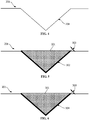
FIG. 4 is a cross-section view taken along line 4-4 inFIG. 3 . -
FIG. 5 is a cross-section view taken along line 5-5 inFIG. 3 . -
FIG. 6 is a cross-section view taken along line 6-6 inFIG. 3 . - Wherever possible, the same reference numbers will be used throughout the drawings to represent the same parts.
- The detailed description set forth below in connection with the appended drawings where like numerals reference like elements is intended as a description of various embodiments of the disclosed subject matter and is not intended to represent the only embodiments. Each embodiment described in this disclosure is provided merely as an example or illustration and should not be construed as preferred or advantageous over other embodiments. The illustrative examples provided herein are not intended to be exhaustive or to limit the claimed subject matter to the precise forms disclosed.
- All numbers expressing quantities of ingredients and/or reaction conditions are to be understood as being modified in all instances by the term "about", unless otherwise indicated.
- The articles "a" and "an," as used herein, mean one or more when applied to any feature in embodiments of the present invention described in the specification and claims. The use of "a" and "an" does not limit the meaning to a single feature unless such a limit is specifically stated. The article "the" preceding singular or plural nouns or noun terms denotes a particular specified feature or particular specified features and may have a singular or plural connotation depending upon the context in which it is used. The adjective "any" means one, some, or all indiscriminately of whatever quantity.
- All percentages and ratios are calculated by weight unless otherwise indicated. All percentages are calculated based on the total weight of a composition unless otherwise indicated. All component or composition levels are in reference to the active level of that component or composition, and are exclusive of impurities, for example, residual solvents or by-products, which may be present in commercially available sources.
- The term "tapered", as used herein, and variations of this term, refer to any shape diminishing, reducing, or causing to diminish or reduce in thickness toward one end. In some embodiments, the cross section of "tapered" shape may include, but not be limited to, a V-shape and a U-shape.
- The term "non-tapered", as used herein, and variations of this term, refer to any shape being constant in thickness toward one end. In some embodiments, the cross-section of "non-tapered" shape may include, but not be limited to, a-shape.

- The term "machining", as used herein, and variations of this term, refer to any process that is capable of controllably removing material from a component. Examples of machining include, but are not limited to post-fabrication drilling, electrical discharge machining (EDM), laser drilling, mechanical drilling, vibrational drilling, milling, computer numerical control milling, water jet cutting, abrasive jet cutting, punching, formation by an additive manufacturing technique, 3D printing, or combinations thereof.
- The present invention may comprise an embodiment including a method for treating a component with a controlled narrow brazing gap size to provide the component with a great mechanical strength. The component herein illustrated may comprise a metal or an alloy. The alloy may comprise a superalloy. The term "superalloy" is used herein as it is commonly used in the art; i.e., a highly corrosion and oxidation resistant alloy that exhibits excellent mechanical strength and resistance to creep at high temperatures.
- In some embodiments, the component may include, but not be limited to, a single crystal (SX) material, a directionally solidified (DS) material, an equiaxed crystal (EX) material, and combinations thereof.
- In some embodiments, the superalloy may include nickel-based superalloy, cobalt-based superalloy, iron-based superalloy, titanium-based superalloy, or combinations thereof. The superalloy may include, but not be limited to, a material selected from the group consisting of Hastelloy, Inconel alloys, Waspaloy, Rene alloys, such as GTD111, GTD222, GTD444, GTD262, Mar M247, IN100, IN 738, René 80, IN 939, René N2, René N4, René N5, René N6, René 65, René 77 (Udimet 700), René 80, René 88DT,
René 104, René 108, René 125, René 142, René 195, René N500, René N515, IN 706, Nimonic 263, CM247, MarM247, CMSX-4, MGA1400, MGA2400, INCONEL 700, INCONEL 738, INCONEL 792, DS Siemet, CMSX10, PWA1480, PWA1483, PWA1484, TMS-75, TMS-82, Mar-M-200, UDIMET 500, ASTROLOY, and combinations thereof. - As used herein, "ASTROLOY" refers to an alloy including a composition, by weight, of about 15% chromium, about 17% cobalt, about 5.3% molybdenum, about 4% aluminum, about 3.5% titanium, and a balance of nickel.
- As used herein, "DS Siemet" refers to an alloy including a composition, by weight, of about 9% cobalt, about 12.1% chromium, about 3.6% aluminum, about 4% titanium, about 5.2% tantalum, about 3.7% tungsten, about 1.8% molybdenum, and a balance of nickel.
- As used herein, "GTD111" refers to an alloy including a composition, by weight, of about 14% chromium, about 9.5% cobalt, about 3.8% tungsten, about 4.9% titanium, about 3% aluminum, about 0.1% iron, about 2.8% tantalum, about 1.6% molybdenum, about 0.1% carbon, and a balance of nickel.
- As used herein, "GTD262" refers to an alloy including a composition, by weight, of about 22.5% chromium, about 19% cobalt, about 2% tungsten, about 1.35% niobium, about 2.3% titanium, about 1.7% aluminum, about 0.1% carbon, and a balance of nickel.
- As used herein, "GTD444" refers to an alloy including a composition, by weight, of about 7.5% cobalt, about 0.2% iron, about 9.75% chromium, about 4.2% aluminum, about 3.5% titanium, about 4.8% tantalum, about 6% tungsten, about 1.5% molybdenum, about 0.5% niobium, about 0.2% silicon, about 0.15% hafnium, and a balance of nickel.
- As used herein, "MGA1400" refers to an alloy including a composition, by weight, of about 10% cobalt, about 14% chromium, about 4% aluminum, about 2.7% titanium, about 4.7% tantalum, about 4.3% tungsten, about 1.5% molybdenum, about 0.1% carbon, and a balance of nickel.
- As used herein, "MGA2400" refers to an alloy including a composition, by weight, of about 19% cobalt, about 19% chromium, about 1.9% aluminum, about 3.7% titanium, about 1.4% tantalum, about 6% tungsten, about 1% niobium, about 0.1% carbon, and a balance of nickel.
- As used herein, "PMA 1480" refers to an alloy including a composition, by weight, of about 10% chromium, about 5% cobalt, about 5% aluminum, about 1.5% titanium, about 12% tantalum, about 4% tungsten, and a balance of nickel.
- As used herein, "PWA1483" refers to an alloy including a composition, by weight, of about 9% cobalt, about 12.2% chromium, about 3.6% aluminum, about 4.1% titanium, about 5% tantalum, about 3.8% tungsten, about 1.9% molybdenum, and a balance of nickel.
- As used herein, "PMA 1484" refers to an alloy including a composition, by weight, of about 5% chromium, about 10% cobalt, about 2% molybdenum, about 5.6% aluminum, about 9% tantalum, about 6% tungsten, and a balance of nickel.
- As used herein, "René N2" refers to an alloy including a composition, by weight, of about 7.5% cobalt, about 13% chromium, about 6.6% aluminum, about 5% tantalum, about 3.8% tungsten, about 1.6% rhenium, about 0.15% hafnium, and a balance of nickel.
- As used herein, "René N4" refers to an alloy including a composition, by weight, of about 9.75% chromium, about 7.5% cobalt, about 4.2% aluminum, about 3.5% titanium, about 1.5% molybdenum, about 6.0% tungsten, about 4.8% tantalum, about 0.5% niobium, about 0.15% hafnium, and a balance of nickel.
- As used herein, "René N5" refers to an alloy including a composition, by weight, of about 7.5% cobalt, about 7.0% chromium, about 6.5% tantalum, about 6.2% aluminum, about 5.0% tungsten, about 3.0% rhenium, about 1.5% molybdenum, about 0.15% hafnium, and a balance of nickel.
- As used herein, "René N6" refers to an alloy including a composition, by weight, of about 12.5% cobalt, about 4.2% chromium, about 7.2% tantalum, about 5.75% aluminum, about 6% tungsten, about 5.4% rhenium, about 1.4% molybdenum, about 0.15% hafnium, and a balance of nickel.
- As used herein, "René 65" refers to an alloy including a composition, by weight, of about 13% cobalt, up to about 1.2% iron, about 16% chromium, about 2.1% aluminum, about 3.75% titanium, about 4% tungsten, about 4% molybdenum, about 0.7% niobium, up to about 0.15% manganese, and a balance of nickel.
- As used herein, "René 77 (Udimet 700)" refers to an alloy including a composition, by weight, of about 15% chromium, about 17% cobalt, about 5.3% molybdenum, about 3.35% titanium, about 4.2% aluminum, and a balance of nickel.
- As used herein, "René 80" refers to an alloy including a composition, by weight, of about 14% chromium, about 9.5% cobalt, about 4% molybdenum, about 3% aluminum, about 5% titanium, about 4% tungsten, about 0.17% carbon, and a balance of nickel.
- As used herein, "René 88DT" refers to an alloy including a composition, by weight, of about 16% chromium, about 13% cobalt, about 4% molybdenum, about 0.7% niobium, about 2.1% aluminum, about 3.7% titanium, about 4% tungsten, about 0.1% rhenium, a maximum of about 4.3% rhenium and tungsten, and a balance of nickel.
- As used herein, "
René 104" refers to an alloy including a composition, by weight, of about 13.1% chromium, about 18.2% cobalt, about 3.8% molybdenum, about 1.9% tungsten, about 1.4% niobium, about 3.5% aluminum, about 3.5% titanium, about 2.7% tantalum, and a balance of nickel. - As used herein, "René 108" refers to an alloy including a composition, by weight, of about 8.4% chromium, about 9.5% cobalt, about 5.5% aluminum, about 0.7% titanium, about 9.5% tungsten, about 0.5% molybdenum, about 3% tantalum, about 1.5% hafnium, and a balance of nickel.
- As used herein, "René 125" refers to an alloy including a composition, by weight, of about 8.5% chromium, about 10% cobalt, about 4.8% aluminum, up to about 2.5% titanium, about 8% tungsten, up to about 2% molybdenum, about 3.8% tantalum, about 1.4% hafnium, about 0.11% carbon, and a balance of nickel.
- As used herein, "René 142" refers to an alloy including a composition, by weight, of about 6.8% chromium, about 12% cobalt, about 6.1% aluminum, about 4.9% tungsten, about 1.5% molybdenum, about 2.8% rhenium, about 6.4% tantalum, about 1.5% hafnium, and a balance of nickel.
- As used herein, "René 195" refers to an alloy including a composition, by weight, of about 7.6% chromium, about 3.1% cobalt, about 7.8% aluminum, about 5.5% tantalum, about 0.1% molybdenum, about 3.9% tungsten, about 1.7% rhenium, about 0.15% hafnium, and a balance of nickel.
- As used herein, "René N500" refers to an alloy including a composition, by weight, of about 7.5% cobalt, about 0.2% iron, about 6% chromium, about 6.25% aluminum, about 6.5% tantalum, about 6.25% tungsten, about 1.5% molybdenum, about 0.15% hafnium, and a balance of nickel.
- As used herein, "René N515" refers to an alloy including a composition, by weight, of about 7.5% cobalt, about 0.2% iron, about 6% chromium, about 6.25% aluminum, about 6.5% tantalum, about 6.25% tungsten, about 2% molybdenum, about 0.1% niobium, about 1.5% rhenium, about 0.6% hafnium, and a balance of nickel.
- As used herein, "MarM247" and "CM247" refer to an alloy including a composition, by weight, of about 5.5% aluminum, about 0.15% carbon, about 8.25% chromium, about 10% cobalt, about 10% tungsten, about 0.7% molybdenum, about 0.5% iron, about 1% titanium, about 3% tantalum, about 1.5% hafnium, and a balance of nickel.
- As used herein, "IN100" refers to an alloy including a composition, by weight, of about 10% chromium, about 15% cobalt, about 3% molybdenum, about 4.7% titanium, about 5.5% aluminum, about 0.18% carbon, and a balance of nickel.
- As used herein, "INCONEL 700" refers to an alloy including a composition, by weight, of up to about 0.12% carbon, about 15% chromium, about 28.5% cobalt, about 3.75% molybdenum, about 2.2% titanium, about 3% aluminum, about 0.7% iron, up to about 0.3% silicon, up to about 0.1% manganese, and a balance of nickel.
- As used herein, "INCONEL 738" refers to an alloy including a composition, by weight, of about 0.17% carbon, about 16% chromium, about 8.5% cobalt, about 1.75% molybdenum, about 2.6% tungsten, about 3.4% titanium, about 3.4% aluminum, about 0.1% zirconium, about 2% niobium, and a balance of nickel.
- As used herein, "INCONEL 792" refers to an alloy including a composition, by weight, of about 12.4% chromium, about 9% cobalt, about 1.9% molybdenum, about 3.8% tungsten, about 3.9% tantalum, about 3.1% aluminum, about 4.5% titanium, about 0.12% carbon, about 0.1% zirconium, and a balance of nickel.
- As used herein, "UDIMET 500" refers to an alloy including a composition, by weight, of about 18.5% chromium, about 18.5% cobalt, about 4% molybdenum, about 3% titanium, about 3% aluminum, and a balance of nickel.
- As used herein, "Mar-M-200" refers to an alloy including a composition, by weight, of about 9% chromium, about 10% cobalt, about 12.5% tungsten, about 1% niobium, about 5% aluminum, about 2% titanium, about 10.14% carbon, about 1.8% hafnium, and a balance of nickel.
- As used herein, "TMS-75" refers to an alloy including a composition, by weight, of about 3% chromium, about 12% cobalt, about 2% molybdenum, about 6% tungsten, about 6% aluminum, about 6% tantalum, about 5% rhenium, about 0.1% hafnium, and a balance of nickel.
- As used herein, "TMS-82" refers to an alloy including a composition, by weight, of about 4.9% chromium, about 7.8% cobalt, about 1.9% molybdenum, about 2.4% rhenium, about 8.7% tungsten, about 5.3% aluminum, about 0.5% titanium, about 6% tantalum, about 0.1% hafnium, and a balance of nickel.
- As used herein, "CMSX-4" refers to an alloy including a composition, by weight, of about 6.4% chromium, about 9.6% cobalt, about 0.6% molybdenum, about 6.4% tungsten, about 5.6% aluminum, about 1.0% titanium, about 6.5% tantalum, about 3% rhenium, about 0.1% hafnium, and a balance of nickel.
- As used herein, "CMSX-10" refers to an alloy including a composition, by weight, of about 2% chromium, about 3% cobalt, about 0.4% molybdenum, about 5% tungsten, about 5.7% aluminum, about 0.2% titanium, about 8% tantalum, about 6% rhenium, and a balance of nickel.
- Any of the alloy compositions described herein may include incidental impurities.
- One embodiment according to the present disclosure includes a method to fabricate a diffusion alloy insert utilized for brazing structural joints with a controlled narrow gap size. The method according to the present disclosure may effectively conduct structural repair of hard-to-weld superalloy. This method may be also utilized for any geometry of insert, and minimize the amount of damaged and/or cracked casting base metal to be removed.
- With reference to
FIG. 1 , a flow chart illustrating a method for treating a component is provided. The method for treating a component includes astep 101 of machining a tapered slot in the component to remove a defect-containing portion of the component. In astep 102, the tapered slot is measured to determine the tapered slot dimension. In astep 103, an insert is formed to have a corresponding geometry to the tapered slot with a braze gap between an outer surface of the insert and an inner surface of the tapered slot. In astep 104, a layer of a braze material is deposited on the outer surface of the insert, where a thickness of the layer corresponds to the braze gap. In astep 105, the layer of the braze material is sintered on the outer surface of the insert to fabricate a diffusion layer. In astep 106, the insert is positioned into the tapered slot. In astep 107, the component is brazed to join the insert to the taper slot of the component. - With reference to
FIG. 2 , acomponent 201 of atreatment system 200 includes atreatment region 202. Thecomponent 201 may be fabricated from any suitable metal or alloy. For example, suitable metals for use ascomponent 201 include but are not limited to superalloys. In particular,component 201 may include nickel cobalt iron-based or titanium based superalloys. The metal alloys may comprise superalloys. Thetreatment region 202 includes a damaged and/or crackedportion 203.Enlarged portion 205 shows a magnified view oftreatment region 202. In some embodiments, the damaged and/or crackedportion 203 may include, but not be limited to, a leading edge, or trailing edge cracks. - With reference to
FIGs. 1 and3 , the method for treating acomponent 201 includes machining a taperedslot 204 in thecomponent 201 to remove a defect-containing portion of the component 201 (step 101). In some embodiments,step 101 includes a step of machining a non-tapered slot in the component to remove a portion of thecomponent 201. For example, the machining may include post-fabrication drilling, electrical discharge machining (EDM), laser drilling, mechanical drilling, vibrational drilling, milling, computer numerical control milling, water jet cutting, abrasive jet cutting, punching, formation by an additive manufacturing technique, 3D printing, or combinations thereof. - The method further includes measuring tapered
slot 204 to determine the tapered slot dimensions (step 102). In certain embodiments, the measuring may further include measuring techniques, such as, but not be limited to, utilizing a white light 3D measurement system, a blue light 3D measurement system, a laser based measuring system, or combinations thereof. The method further includes forming aninsert 301 of aninsert system 300 to have a corresponding geometry to the tapered slot 204 (step 103).Insert 301 is formed with a geometry that provides abraze gap 303 between an outer surface of theinsert 301 and an inner surface of the taperedslot 204, wheninsert 301 is inserted in taperedslot 204. In one embodiment, the tapered slot dimensions may be determined, for example, by a blue light 3D measurement system. - The forming 103 may include, but not be limited to post-fabrication drilling, electrical discharge machining (EDM), laser drilling, mechanical drilling, vibrational drilling, milling, computer numerical control milling, water jet cutting, abrasive jet cutting, punching, formation by an additive manufacturing technique, 3D printing, or combinations thereof. In one embodiment, the forming includes machining a material to the designed geometry.
- The
braze gap 303 may be formed between theinsert 301 and the inner surface of taperedslot 204 sufficiently small to provide a tensile strength greater than about 500 MPa at room temperature. Thus, in various embodiments, the braze gap may be sufficiently small to provide a tensile strength greater than 600 MPa, greater than 700 MPa, and greater than 800 MPa, greater than 900 MPa, and greater than 1000 MPa at room temperature. In one embodiment, the braze gap may be between about 0.0005 inches and 0.01 inches. Thus, in various embodiments, the braze gap may be from about 0.0005 to about 0.010 inches, from about 0.0010 to about 0.0095 inches, from about 0.0015 to about 0.0090 inches, from about 0.0020 to about 0.0085 inches, from about 0.0025 to about 0.0080 inches, from about 0.0030 to about 0.0075 inches, from about 0.0035 to about 0.0065 inches, from about 0.0040 to about 0.0060 inches, or from about 0.0045 to about 0.0055 inches, including increments and intervals therein. - The
insert 301 may include, but not be limited to, a single crystal (SX) material, a directionally solidified (DS) material, an equiaxed crystal (EX) material, and combinations thereof. In one embodiment, insert 301 includes a material that is the same as a material ofcomponent 201. In another embodiment, insert 301 includes a material that is dissimilar from a material ofcomponent 201. - Also with to
FIG. 3 , the method includes depositing a layer of braze material on the outer surface of the insert (step 104). In one embodiment, the thickness of the layer may correspond to thebraze gap 303 between the outer surface of theinsert 301 and the inner surface of taperedslot 204. The depositing may include, but not be limited to, powder spray, tape or foil deposition, physical vapor deposition (PVD), chemical vapor deposition (CVD), thermal spray, electrodeposition, hot dipping, cold dipping, laser based deposition, welding based deposition, and combinations thereof. Braze material may include, but not be limited to, gold, copper, silver, platinum, palladium, nickel, titanium, vanadium, zirconium, cobalt, and combinations thereof. The method includes sintering the layer of braze material on the outer surface of theinsert 301 to fabricate diffusion layer 302 (step 105). - Sintering may be conducted at a temperature between about 1800 and about 2300° F. Thus, in various embodiments, the sintering may be conducted at a temperature from about 1800 to about 2300° F, from about 1850 to about 2250° F, from about 1900 to about 2200° F, from about 1950 to about 2150° F, or from about 2000 to about 2100° F, preferably from about 1900 to about 2175° F, including increments and intervals therein. The sintering may be conducted in inert gas environment. The sintering, for example, may be conducted in either a vacuum or hydrogen furnace. The sintering temperature may be sufficient to transform the layer of braze material into
diffusion layer 302. - The method further includes positioning the
insert 301 with thediffusion layer 302 into the tapered slot 204 (step 106). Theinsert 301 may be positioned into the taperedslot 204 with tight/press fit. - The method further includes
brazing diffusion layer 302 to joininsert 301 to the component 201 (step 107). The brazing may be conducted at a temperature sufficient to melt at least a portion ofdiffusion layer 302 but not thecomponent 201. The melt portion ofdiffusion layer 302 may bond theinsert 301 to thecomponent 201 with a narrow braze gap size. Thus, in various embodiments, the brazing may be conducted at a temperature from about 1800 to about 2350° F, from about 1850 to about 2300 ° F, from about 1900 to about 2250° F, from about 1950 to about 2200 ° F, from about 2000 to about 2150° F, or from about 2050 to about 2100° F, including increments and intervals therein. In one embodiment, the brazing may be conducted at a temperature between about 1800 and about 2350° F, preferably from about 2050 to about 2225° F. The brazing may be conducted along with a thermal cycle. - While the invention has been described with reference to a preferred embodiment, it will be understood by those skilled in the art that various changes may be made and equivalents may be substituted for elements thereof without departing from the scope of the invention. In addition, many modifications may be made to adapt a particular situation or material to the teachings of the invention without departing from the essential scope thereof. Therefore, it is intended that the invention not be limited to the particular embodiment disclosed as the best mode contemplated for carrying out this invention, but that the invention will include all embodiments falling within the scope of the appended claims.
- Various aspects and embodiments of the present invention are defined by the following clauses:
- 1. A method for treating a component comprising the steps of:
- machining a tapered slot in the component to remove a portion of the component;
- measuring the tapered slot to determine the tapered slot dimensions;
- forming an insert to have a corresponding geometry to the tapered slot with a braze gap between an outer surface of the insert and an inner surface of the tapered slot;
- depositing a layer of a braze material on the outer surface of the insert;
- sintering the layer of the braze material on the outer surface of the insert to fabricate a diffusion layer;
- positioning the insert into the tapered slot; and
- brazing the component to join the insert to the component.
- 2. The method of clause 1, wherein the measuring comprises utilizing a measurement system selected from the group consisting of white light 3D measurement system, a blue light 3D measurement system, a laser based measuring system, and combinations thereof.
- 3. The method of clause 1, wherein the forming the insert comprises machining.
- 4. The method of clause 1, wherein the forming the insert comprises a process selected from the group consisting of post-fabrication drilling, electrical discharge machining (EDM), laser drilling, mechanical drilling, vibrational drilling, milling, computer numerical control milling, water jet cutting, abrasive jet cutting, punching, formation by an additive manufacturing technique, 3D printing, and combinations thereof.
- 5. The method of clause 1, wherein the depositing comprises a process selected from the group consisting of powder spray, tape or foil deposition, physical vapor deposition (PVD), chemical vapor deposition (CVD), thermal spray, electrodeposition, hot dipping, cold dipping, laser based deposition, welding based deposition, and combinations thereof.
- 6. The method of clause 1, wherein a thickness of the layer is the same as the braze gap spaced between the outer surface of the insert and the inner surface of the tapered slot.
- 7. The method of clause 1, wherein the component comprises an alloy.
- 8. The method of clause 7, wherein the alloy comprises a superalloy material selected from the group consisting of nickel-based superalloy, cobalt-based superalloy, iron-based superalloy, titanium-based superalloy, and combinations thereof.
- 9. The method of clause 1, wherein the component comprises a material selected from the group consisting of a single crystal (SX) material, a directionally solidified (DS) material, an equiaxed crystal (EX) material, and combinations thereof.
- 10. The method of clause 1, wherein the insert comprises a material selected from the group consisting of a single crystal (SX) material, a directionally solidified (DS) material, an equiaxed crystal (EX) material, and combinations thereof.
- 11. The method of clause 1, wherein the insert includes a material that is the same as a material of the component.
- 12. The method of clause 1, wherein the insert includes a material that is dissimilar from a material of the component.
- 13. The method of clause 1, wherein the braze gap is sufficiently small to provide a tensile strength of greater than about 500 MPa at room temperature.
- 14. The method of clause 1, wherein the braze gap is between about 0.0005 and about 0.01 inches.
- 15. The method of clause 1, wherein the braze material comprises a material selected from the group consisting of gold, copper, silver, platinum, palladium, nickel, titanium, vanadium, zirconium, cobalt, and combinations thereof.
- 16. The method of clause 1, wherein the sintering is conducted at a temperature between about 1800 and about 2300° F.
- 17. The method of clause 1, wherein the brazing is conducted at a temperature between about 1800 and about 2350° F.
- 18. The method of clause 1, wherein the component is a turbine component selected from the group consisting of at least one of blades (buckets), vanes (nozzles), shrouds, combustor liners, and transition ducts.
- 19. A method for treating a superalloy turbine component comprising the steps of:
- machining a tapered slot in the superalloy turbine component to remove a defect-containing portion of the superalloy turbine component;
- measuring the tapered slot to determine the tapered slot dimensions;
- forming an insert to have a corresponding geometry to the tapered slot with a braze gap ranging from about 0.0005 to about 0.01 inches between an outer surface of the insert and an inner surface of the tapered slot;
- depositing a layer of a braze material on the outer surface of the insert;
- sintering the layer of the braze material on the outer surface of the insert to fabricate a diffusion layer at a temperature between about 1800 and about 2300° F;
- positioning the insert into the tapered slot; and
- brazing the superalloy turbine component to join the insert to the superalloy turbine component at a temperature between about 1800 and about 2350 ° F.
- 20. A treated superalloy turbine component comprising:
- a surface having a tapered slot;
- an insert positioned to the tapered slot with a braze gap ranging from 0.0005 to 0.01 inches between an outer surface of the insert and an inner surface of the tapered slot; and
- a braze joint comprising a braze material positioned in the braze gap, the braze material having been sintered on the outer surface of the insert, the superalloy turbine component having a diffusion layer between the insert and the superalloy turbine component.
Claims (15)
- A method (100) for treating a component (201) comprising the steps of:machining (101) a tapered slot (204) in the component (201) to remove a portion (203) of the component (201);measuring (102) the tapered slot (204) to determine the tapered slot (204) dimensions;forming (103) an insert (301) to have a corresponding geometry to the tapered slot (204) with a braze gap (303) between an outer surface of the insert (301) and an inner surface of the tapered slot (204);depositing (104) a layer of a braze material on the outer surface of the insert (301);sintering (105) the layer of the braze material on the outer surface of the insert (301) to fabricate a diffusion layer (302);positioning (106) the insert (301) into the tapered slot (204); andbrazing (107) the component (201) to join the insert (301) to the component (201).
- The method (100) of claim 1, wherein the measuring (102) comprises utilizing a measurement system selected from the group consisting of white light 3D measurement system, a blue light 3D measurement system, a laser based measuring system, and combinations thereof.
- The method (100) of claim 1 or 2, wherein the forming (103) the insert (301) comprises a process selected from the group consisting of post-fabrication drilling, electrical discharge machining (EDM), laser drilling, mechanical drilling, vibrational drilling, milling, computer numerical control milling, water jet cutting, abrasive jet cutting, punching, formation by an additive manufacturing technique, 3D printing, and combinations thereof.
- The method (100) of any one of claims 1 to 3, wherein the depositing (104) comprises a process selected from the group consisting of powder spray, tape or foil deposition, physical vapor deposition (PVD), chemical vapor deposition (CVD), thermal spray, electrodeposition, hot dipping, cold dipping, laser based deposition, welding based deposition, and combinations thereof.
- The method (100) of any one of claims 1 to 4, wherein a thickness of the layer is the same as the braze gap (303) spaced between the outer surface of the insert (301) and the inner surface of the tapered slot (204).
- The method (100) of any one of claims 1 to 5, wherein the component (201) comprises an alloy or superalloy material selected from the group consisting of nickel-based superalloy, cobalt-based superalloy, iron-based superalloy, titanium-based superalloy, and combinations thereof.
- The method (100) of any one of claims 1 to 6, wherein the component (201) comprises a material selected from the group consisting of a single crystal (SX) material, a directionally solidified (DS) material, an equiaxed crystal (EX) material, and combinations thereof.
- The method (100) of any one of claims 1 to 7, wherein the insert (301) comprises a material selected from the group consisting of a single crystal (SX) material, a directionally solidified (DS) material, an equiaxed crystal (EX) material, and combinations thereof.
- The method (100) of any one of claims 1 to 8, wherein the braze gap (303) is sufficiently small to provide a tensile strength of greater than 500 MPa at room temperature.
- The method (100) of any one of claims 1 to 9, wherein the braze gap (303) is between 0.0005 and 0.01 inches.
- The method (100) of any one of claims 1 to 10, wherein the braze material comprises a material selected from the group consisting of gold, copper, silver, platinum, palladium, nickel, titanium, vanadium, zirconium, cobalt, and combinations thereof.
- The method (100) of any one of claims 1 to 11, wherein the sintering (105) is conducted at a temperature between 1800 and 2300° F.
- The method (100) of any one of claims 1 to 12, wherein the brazing (107) is conducted at a temperature between 1800 and 2350° F.
- The method (100) of any one of claims 1 to 13, wherein the component (201) is a turbine component (201) selected from the group consisting of at least one of blades (buckets), vanes (nozzles), shrouds, combustor liners, and transition ducts.
- A treated superalloy turbine component (201) comprising:a surface having a tapered slot (204);an insert (301) positioned to the tapered slot (204) with a braze gap (303) ranging from 0.0005 to 0.01 inches between an outer surface of the insert (301) and an inner surface of the tapered slot (204); anda braze joint comprising a braze material positioned in the braze gap (303), the braze material having been sintered on the outer surface of the insert (301), the superalloy turbine component (201) having a diffusion layer (302) between the insert (301) and the superalloy turbine component (201).
Applications Claiming Priority (1)
| Application Number | Priority Date | Filing Date | Title |
|---|---|---|---|
| US15/397,840 US20180187564A1 (en) | 2017-01-04 | 2017-01-04 | Structure braze of hard-to-weld superalloy components using diffusion alloy insert |
Publications (2)
| Publication Number | Publication Date |
|---|---|
| EP3345718A1 true EP3345718A1 (en) | 2018-07-11 |
| EP3345718B1 EP3345718B1 (en) | 2022-03-23 |
Family
ID=60654729
Family Applications (1)
| Application Number | Title | Priority Date | Filing Date |
|---|---|---|---|
| EP17205952.9A Active EP3345718B1 (en) | 2017-01-04 | 2017-12-07 | Structure braze repair of hard-to-weld superalloy components using diffusion alloy insert |
Country Status (3)
| Country | Link |
|---|---|
| US (1) | US20180187564A1 (en) |
| EP (1) | EP3345718B1 (en) |
| JP (1) | JP7038545B2 (en) |
Cited By (2)
| Publication number | Priority date | Publication date | Assignee | Title |
|---|---|---|---|---|
| CN110253207A (en) * | 2019-07-17 | 2019-09-20 | 孙京钢 | A kind of curling furnace drum crack restorative procedure |
| GB2624020A (en) * | 2022-11-04 | 2024-05-08 | Gkn Aerospace Sweden Ab | IBR blade repair |
Families Citing this family (9)
| Publication number | Priority date | Publication date | Assignee | Title |
|---|---|---|---|---|
| CN110405319A (en) * | 2019-08-15 | 2019-11-05 | 江苏京成机械制造有限公司 | The process for welding repair of heat resisting cast steel ZG40Cr24Ni9Si2NRe |
| US11612947B2 (en) | 2020-01-06 | 2023-03-28 | Rolls-Royce Corporation | Method of diffusion bonding utilizing vapor deposition |
| US20230347434A1 (en) * | 2022-04-28 | 2023-11-02 | Rolls-Royce Corporation | Pulsed electrochemical machining of turbine components |
| US12544845B2 (en) * | 2023-10-27 | 2026-02-10 | Ge Infrastructure Technology Llc | Porous metal coupon with braze material infiltration barrier for repairing component, component with same and related method |
| US20250135588A1 (en) * | 2023-10-27 | 2025-05-01 | Ge Infrastructure Technology Llc | Braze repair using metal coupon with porous region |
| US12576614B2 (en) | 2023-10-27 | 2026-03-17 | Ge Infrastructure Technology Llc | Porous metal coupon with thermal transfer structure for component and related component |
| US12502713B2 (en) | 2023-10-27 | 2025-12-23 | Ge Infrastructure Technology Llc | Porous metal coupon with sealed cavity for repairing component, component with same and related method |
| US12605768B2 (en) | 2023-10-27 | 2026-04-21 | Ge Infrastructure Technology Llc | Porous metal coupon with low porosity region for repairing component, component with same and related method |
| US12528133B2 (en) | 2024-01-19 | 2026-01-20 | Ge Infrastructure Technology Llc | Metal coupon with braze reservoir for component, component with same and related method |
Citations (4)
| Publication number | Priority date | Publication date | Assignee | Title |
|---|---|---|---|---|
| US20030034379A1 (en) * | 2001-08-16 | 2003-02-20 | Jackson Melvin Robert | Method of repairing superalloy directional castings |
| EP2078579A1 (en) * | 2008-01-10 | 2009-07-15 | Siemens Aktiengesellschaft | Method for soldering one component and component with soldering and welding points |
| US20150047168A1 (en) * | 2013-08-13 | 2015-02-19 | Allister William James | Repair chain for turbomachinery components using additive manufacturing technology |
| DE102013224103A1 (en) * | 2013-11-26 | 2015-06-11 | Siemens Aktiengesellschaft | Safe plug closure by diffusion coating and process |
Family Cites Families (6)
| Publication number | Priority date | Publication date | Assignee | Title |
|---|---|---|---|---|
| US6508000B2 (en) | 2001-02-08 | 2003-01-21 | Siemens Westinghouse Power Corporation | Transient liquid phase bonding repair for advanced turbine blades and vanes |
| US6883700B2 (en) * | 2002-09-26 | 2005-04-26 | Siemens Westinghouse Power Corporation | Turbine blade closure system |
| US7322396B2 (en) * | 2005-10-14 | 2008-01-29 | General Electric Company | Weld closure of through-holes in a nickel-base superalloy hollow airfoil |
| US7784668B2 (en) * | 2005-12-16 | 2010-08-31 | United Technologies Corporation | Repair method for propagating epitaxial crystalline structures by heating to within 0-100° f of the solidus |
| ATE482774T1 (en) * | 2008-01-10 | 2010-10-15 | Mettler Toledo Ag | WORK CABIN WITH EXTERNAL PRINTER |
| ES2402257T3 (en) | 2009-10-30 | 2013-04-30 | Alstom Technology Ltd | Method to repair a component of a gas turbine |
-
2017
- 2017-01-04 US US15/397,840 patent/US20180187564A1/en not_active Abandoned
- 2017-12-07 EP EP17205952.9A patent/EP3345718B1/en active Active
- 2017-12-22 JP JP2017245718A patent/JP7038545B2/en active Active
Patent Citations (4)
| Publication number | Priority date | Publication date | Assignee | Title |
|---|---|---|---|---|
| US20030034379A1 (en) * | 2001-08-16 | 2003-02-20 | Jackson Melvin Robert | Method of repairing superalloy directional castings |
| EP2078579A1 (en) * | 2008-01-10 | 2009-07-15 | Siemens Aktiengesellschaft | Method for soldering one component and component with soldering and welding points |
| US20150047168A1 (en) * | 2013-08-13 | 2015-02-19 | Allister William James | Repair chain for turbomachinery components using additive manufacturing technology |
| DE102013224103A1 (en) * | 2013-11-26 | 2015-06-11 | Siemens Aktiengesellschaft | Safe plug closure by diffusion coating and process |
Cited By (3)
| Publication number | Priority date | Publication date | Assignee | Title |
|---|---|---|---|---|
| CN110253207A (en) * | 2019-07-17 | 2019-09-20 | 孙京钢 | A kind of curling furnace drum crack restorative procedure |
| GB2624020A (en) * | 2022-11-04 | 2024-05-08 | Gkn Aerospace Sweden Ab | IBR blade repair |
| GB2624020B (en) * | 2022-11-04 | 2025-07-02 | Gkn Aerospace Sweden Ab | IBR blade repair |
Also Published As
| Publication number | Publication date |
|---|---|
| US20180187564A1 (en) | 2018-07-05 |
| JP7038545B2 (en) | 2022-03-18 |
| JP2018168851A (en) | 2018-11-01 |
| EP3345718B1 (en) | 2022-03-23 |
Similar Documents
| Publication | Publication Date | Title |
|---|---|---|
| EP3345718B1 (en) | Structure braze repair of hard-to-weld superalloy components using diffusion alloy insert | |
| US11731206B2 (en) | Repair of through-hole damage using braze sintered preform | |
| CN112760525B (en) | High gamma prime nickel-based superalloy, use thereof and method of manufacturing a turbine engine component | |
| EP1721697B2 (en) | Superalloy repair methods and inserts | |
| JP2018168851A5 (en) | ||
| KR101613152B1 (en) | Braze alloy for high-temperature brazing and methods for repairing or producing components using said braze alloy | |
| US6742698B2 (en) | Refractory metal backing material for weld repair | |
| EP3412784B1 (en) | Method of treating superalloy articles | |
| EP2684981B1 (en) | A coating/repairing process using electrospark with PSP rod | |
| EP3351730A1 (en) | Component and method for forming a component | |
| JP2006188760A (en) | Method of repairing nickel-base superalloy, preform for repair, and component repaired thereby | |
| CN104923956A (en) | Weld filler for nickel-base superalloys | |
| JP2011062749A (en) | Superalloy composition and method of forming turbine engine component | |
| WO2019014445A1 (en) | Method of repairing an article and associated article | |
| EP3385019B1 (en) | Clad article and method for forming clad article | |
| US20180209288A1 (en) | Braze system, brazed article, and method for forming a brazed article | |
| JP7076948B2 (en) | Articles, components, and methods of making components | |
| HK40050043A (en) | High gamma prime nickel based superalloy, its use, turbine components and method of manufacturing thereof | |
| HK40050043B (en) | High gamma prime nickel based superalloy, its use, turbine components and method of manufacturing thereof | |
| HK40048693B (en) | High gamma prime nickel based superalloy, its use, and method of manufacturing of turbine engine components | |
| HK40048693A (en) | High gamma prime nickel based superalloy, its use, and method of manufacturing of turbine engine components | |
| KR20250153295A (en) | Oxidation-resistant nickel-based alloy and method | |
| Sparling et al. | Liburdi Power Metallurgy: New Compositions for High Strength Repairs of Turbine Components |
Legal Events
| Date | Code | Title | Description |
|---|---|---|---|
| PUAI | Public reference made under article 153(3) epc to a published international application that has entered the european phase |
Free format text: ORIGINAL CODE: 0009012 |
|
| STAA | Information on the status of an ep patent application or granted ep patent |
Free format text: STATUS: THE APPLICATION HAS BEEN PUBLISHED |
|
| AK | Designated contracting states |
Kind code of ref document: A1 Designated state(s): AL AT BE BG CH CY CZ DE DK EE ES FI FR GB GR HR HU IE IS IT LI LT LU LV MC MK MT NL NO PL PT RO RS SE SI SK SM TR |
|
| AX | Request for extension of the european patent |
Extension state: BA ME |
|
| STAA | Information on the status of an ep patent application or granted ep patent |
Free format text: STATUS: REQUEST FOR EXAMINATION WAS MADE |
|
| 17P | Request for examination filed |
Effective date: 20190111 |
|
| RBV | Designated contracting states (corrected) |
Designated state(s): AL AT BE BG CH CY CZ DE DK EE ES FI FR GB GR HR HU IE IS IT LI LT LU LV MC MK MT NL NO PL PT RO RS SE SI SK SM TR |
|
| GRAP | Despatch of communication of intention to grant a patent |
Free format text: ORIGINAL CODE: EPIDOSNIGR1 |
|
| STAA | Information on the status of an ep patent application or granted ep patent |
Free format text: STATUS: GRANT OF PATENT IS INTENDED |
|
| RIC1 | Information provided on ipc code assigned before grant |
Ipc: B23K 103/18 20060101ALN20211012BHEP Ipc: B23K 101/00 20060101ALN20211012BHEP Ipc: C23C 4/02 20060101ALI20211012BHEP Ipc: B23K 35/32 20060101ALI20211012BHEP Ipc: F01D 5/00 20060101ALI20211012BHEP Ipc: C23C 4/18 20060101ALI20211012BHEP Ipc: C23C 2/28 20060101ALI20211012BHEP Ipc: C23C 2/26 20060101ALI20211012BHEP Ipc: B23K 35/30 20060101ALI20211012BHEP Ipc: B23K 35/22 20060101ALI20211012BHEP Ipc: B23K 35/02 20060101ALI20211012BHEP Ipc: B23K 20/16 20060101ALI20211012BHEP Ipc: B23K 20/02 20060101ALI20211012BHEP Ipc: B23K 1/20 20060101ALI20211012BHEP Ipc: B23K 1/00 20060101ALI20211012BHEP Ipc: B23P 6/00 20060101AFI20211012BHEP |
|
| INTG | Intention to grant announced |
Effective date: 20211029 |
|
| GRAS | Grant fee paid |
Free format text: ORIGINAL CODE: EPIDOSNIGR3 |
|
| GRAA | (expected) grant |
Free format text: ORIGINAL CODE: 0009210 |
|
| STAA | Information on the status of an ep patent application or granted ep patent |
Free format text: STATUS: THE PATENT HAS BEEN GRANTED |
|
| AK | Designated contracting states |
Kind code of ref document: B1 Designated state(s): AL AT BE BG CH CY CZ DE DK EE ES FI FR GB GR HR HU IE IS IT LI LT LU LV MC MK MT NL NO PL PT RO RS SE SI SK SM TR |
|
| REG | Reference to a national code |
Ref country code: GB Ref legal event code: FG4D |
|
| REG | Reference to a national code |
Ref country code: CH Ref legal event code: EP |
|
| REG | Reference to a national code |
Ref country code: DE Ref legal event code: R096 Ref document number: 602017054871 Country of ref document: DE |
|
| REG | Reference to a national code |
Ref country code: IE Ref legal event code: FG4D |
|
| REG | Reference to a national code |
Ref country code: AT Ref legal event code: REF Ref document number: 1477115 Country of ref document: AT Kind code of ref document: T Effective date: 20220415 |
|
| REG | Reference to a national code |
Ref country code: NL Ref legal event code: FP |
|
| REG | Reference to a national code |
Ref country code: LT Ref legal event code: MG9D |
|
| PG25 | Lapsed in a contracting state [announced via postgrant information from national office to epo] |
Ref country code: SE Free format text: LAPSE BECAUSE OF FAILURE TO SUBMIT A TRANSLATION OF THE DESCRIPTION OR TO PAY THE FEE WITHIN THE PRESCRIBED TIME-LIMIT Effective date: 20220323 Ref country code: RS Free format text: LAPSE BECAUSE OF FAILURE TO SUBMIT A TRANSLATION OF THE DESCRIPTION OR TO PAY THE FEE WITHIN THE PRESCRIBED TIME-LIMIT Effective date: 20220323 Ref country code: NO Free format text: LAPSE BECAUSE OF FAILURE TO SUBMIT A TRANSLATION OF THE DESCRIPTION OR TO PAY THE FEE WITHIN THE PRESCRIBED TIME-LIMIT Effective date: 20220623 Ref country code: LT Free format text: LAPSE BECAUSE OF FAILURE TO SUBMIT A TRANSLATION OF THE DESCRIPTION OR TO PAY THE FEE WITHIN THE PRESCRIBED TIME-LIMIT Effective date: 20220323 Ref country code: HR Free format text: LAPSE BECAUSE OF FAILURE TO SUBMIT A TRANSLATION OF THE DESCRIPTION OR TO PAY THE FEE WITHIN THE PRESCRIBED TIME-LIMIT Effective date: 20220323 Ref country code: BG Free format text: LAPSE BECAUSE OF FAILURE TO SUBMIT A TRANSLATION OF THE DESCRIPTION OR TO PAY THE FEE WITHIN THE PRESCRIBED TIME-LIMIT Effective date: 20220623 |
|
| REG | Reference to a national code |
Ref country code: AT Ref legal event code: MK05 Ref document number: 1477115 Country of ref document: AT Kind code of ref document: T Effective date: 20220323 |
|
| PG25 | Lapsed in a contracting state [announced via postgrant information from national office to epo] |
Ref country code: LV Free format text: LAPSE BECAUSE OF FAILURE TO SUBMIT A TRANSLATION OF THE DESCRIPTION OR TO PAY THE FEE WITHIN THE PRESCRIBED TIME-LIMIT Effective date: 20220323 Ref country code: GR Free format text: LAPSE BECAUSE OF FAILURE TO SUBMIT A TRANSLATION OF THE DESCRIPTION OR TO PAY THE FEE WITHIN THE PRESCRIBED TIME-LIMIT Effective date: 20220624 Ref country code: FI Free format text: LAPSE BECAUSE OF FAILURE TO SUBMIT A TRANSLATION OF THE DESCRIPTION OR TO PAY THE FEE WITHIN THE PRESCRIBED TIME-LIMIT Effective date: 20220323 |
|
| PG25 | Lapsed in a contracting state [announced via postgrant information from national office to epo] |
Ref country code: SM Free format text: LAPSE BECAUSE OF FAILURE TO SUBMIT A TRANSLATION OF THE DESCRIPTION OR TO PAY THE FEE WITHIN THE PRESCRIBED TIME-LIMIT Effective date: 20220323 Ref country code: SK Free format text: LAPSE BECAUSE OF FAILURE TO SUBMIT A TRANSLATION OF THE DESCRIPTION OR TO PAY THE FEE WITHIN THE PRESCRIBED TIME-LIMIT Effective date: 20220323 Ref country code: RO Free format text: LAPSE BECAUSE OF FAILURE TO SUBMIT A TRANSLATION OF THE DESCRIPTION OR TO PAY THE FEE WITHIN THE PRESCRIBED TIME-LIMIT Effective date: 20220323 Ref country code: PT Free format text: LAPSE BECAUSE OF FAILURE TO SUBMIT A TRANSLATION OF THE DESCRIPTION OR TO PAY THE FEE WITHIN THE PRESCRIBED TIME-LIMIT Effective date: 20220725 Ref country code: ES Free format text: LAPSE BECAUSE OF FAILURE TO SUBMIT A TRANSLATION OF THE DESCRIPTION OR TO PAY THE FEE WITHIN THE PRESCRIBED TIME-LIMIT Effective date: 20220323 Ref country code: EE Free format text: LAPSE BECAUSE OF FAILURE TO SUBMIT A TRANSLATION OF THE DESCRIPTION OR TO PAY THE FEE WITHIN THE PRESCRIBED TIME-LIMIT Effective date: 20220323 Ref country code: CZ Free format text: LAPSE BECAUSE OF FAILURE TO SUBMIT A TRANSLATION OF THE DESCRIPTION OR TO PAY THE FEE WITHIN THE PRESCRIBED TIME-LIMIT Effective date: 20220323 Ref country code: AT Free format text: LAPSE BECAUSE OF FAILURE TO SUBMIT A TRANSLATION OF THE DESCRIPTION OR TO PAY THE FEE WITHIN THE PRESCRIBED TIME-LIMIT Effective date: 20220323 |
|
| PG25 | Lapsed in a contracting state [announced via postgrant information from national office to epo] |
Ref country code: PL Free format text: LAPSE BECAUSE OF FAILURE TO SUBMIT A TRANSLATION OF THE DESCRIPTION OR TO PAY THE FEE WITHIN THE PRESCRIBED TIME-LIMIT Effective date: 20220323 Ref country code: IS Free format text: LAPSE BECAUSE OF FAILURE TO SUBMIT A TRANSLATION OF THE DESCRIPTION OR TO PAY THE FEE WITHIN THE PRESCRIBED TIME-LIMIT Effective date: 20220723 Ref country code: AL Free format text: LAPSE BECAUSE OF FAILURE TO SUBMIT A TRANSLATION OF THE DESCRIPTION OR TO PAY THE FEE WITHIN THE PRESCRIBED TIME-LIMIT Effective date: 20220323 |
|
| REG | Reference to a national code |
Ref country code: DE Ref legal event code: R097 Ref document number: 602017054871 Country of ref document: DE |
|
| PLBE | No opposition filed within time limit |
Free format text: ORIGINAL CODE: 0009261 |
|
| STAA | Information on the status of an ep patent application or granted ep patent |
Free format text: STATUS: NO OPPOSITION FILED WITHIN TIME LIMIT |
|
| PG25 | Lapsed in a contracting state [announced via postgrant information from national office to epo] |
Ref country code: DK Free format text: LAPSE BECAUSE OF FAILURE TO SUBMIT A TRANSLATION OF THE DESCRIPTION OR TO PAY THE FEE WITHIN THE PRESCRIBED TIME-LIMIT Effective date: 20220323 |
|
| 26N | No opposition filed |
Effective date: 20230102 |
|
| PG25 | Lapsed in a contracting state [announced via postgrant information from national office to epo] |
Ref country code: SI Free format text: LAPSE BECAUSE OF FAILURE TO SUBMIT A TRANSLATION OF THE DESCRIPTION OR TO PAY THE FEE WITHIN THE PRESCRIBED TIME-LIMIT Effective date: 20220323 |
|
| REG | Reference to a national code |
Ref country code: CH Ref legal event code: PL |
|
| GBPC | Gb: european patent ceased through non-payment of renewal fee |
Effective date: 20221207 |
|
| REG | Reference to a national code |
Ref country code: BE Ref legal event code: MM Effective date: 20221231 |
|
| PG25 | Lapsed in a contracting state [announced via postgrant information from national office to epo] |
Ref country code: LU Free format text: LAPSE BECAUSE OF NON-PAYMENT OF DUE FEES Effective date: 20221207 |
|
| PG25 | Lapsed in a contracting state [announced via postgrant information from national office to epo] |
Ref country code: LI Free format text: LAPSE BECAUSE OF NON-PAYMENT OF DUE FEES Effective date: 20221231 Ref country code: IE Free format text: LAPSE BECAUSE OF NON-PAYMENT OF DUE FEES Effective date: 20221207 Ref country code: GB Free format text: LAPSE BECAUSE OF NON-PAYMENT OF DUE FEES Effective date: 20221207 Ref country code: CH Free format text: LAPSE BECAUSE OF NON-PAYMENT OF DUE FEES Effective date: 20221231 |
|
| REG | Reference to a national code |
Ref country code: DE Ref legal event code: R081 Ref document number: 602017054871 Country of ref document: DE Owner name: GENERAL ELECTRIC TECHNOLOGY GMBH, CH Free format text: FORMER OWNER: GENERAL ELECTRIC COMPANY, SCHENECTADY, NY, US |
|
| PG25 | Lapsed in a contracting state [announced via postgrant information from national office to epo] |
Ref country code: FR Free format text: LAPSE BECAUSE OF NON-PAYMENT OF DUE FEES Effective date: 20221231 Ref country code: BE Free format text: LAPSE BECAUSE OF NON-PAYMENT OF DUE FEES Effective date: 20221231 |
|
| PG25 | Lapsed in a contracting state [announced via postgrant information from national office to epo] |
Ref country code: HU Free format text: LAPSE BECAUSE OF FAILURE TO SUBMIT A TRANSLATION OF THE DESCRIPTION OR TO PAY THE FEE WITHIN THE PRESCRIBED TIME-LIMIT; INVALID AB INITIO Effective date: 20171207 |
|
| REG | Reference to a national code |
Ref country code: NL Ref legal event code: PD Owner name: GENERAL ELECTRIC TECHNOLOGY GMBH; CH Free format text: DETAILS ASSIGNMENT: CHANGE OF OWNER(S), ASSIGNMENT; FORMER OWNER NAME: GENERAL ELECTRIC COMPANY Effective date: 20240410 |
|
| PG25 | Lapsed in a contracting state [announced via postgrant information from national office to epo] |
Ref country code: CY Free format text: LAPSE BECAUSE OF FAILURE TO SUBMIT A TRANSLATION OF THE DESCRIPTION OR TO PAY THE FEE WITHIN THE PRESCRIBED TIME-LIMIT Effective date: 20220323 |
|
| PG25 | Lapsed in a contracting state [announced via postgrant information from national office to epo] |
Ref country code: MK Free format text: LAPSE BECAUSE OF FAILURE TO SUBMIT A TRANSLATION OF THE DESCRIPTION OR TO PAY THE FEE WITHIN THE PRESCRIBED TIME-LIMIT Effective date: 20220323 |
|
| PG25 | Lapsed in a contracting state [announced via postgrant information from national office to epo] |
Ref country code: MC Free format text: LAPSE BECAUSE OF FAILURE TO SUBMIT A TRANSLATION OF THE DESCRIPTION OR TO PAY THE FEE WITHIN THE PRESCRIBED TIME-LIMIT Effective date: 20220323 |
|
| PG25 | Lapsed in a contracting state [announced via postgrant information from national office to epo] |
Ref country code: TR Free format text: LAPSE BECAUSE OF FAILURE TO SUBMIT A TRANSLATION OF THE DESCRIPTION OR TO PAY THE FEE WITHIN THE PRESCRIBED TIME-LIMIT Effective date: 20220323 Ref country code: MC Free format text: LAPSE BECAUSE OF FAILURE TO SUBMIT A TRANSLATION OF THE DESCRIPTION OR TO PAY THE FEE WITHIN THE PRESCRIBED TIME-LIMIT Effective date: 20220323 |
|
| PG25 | Lapsed in a contracting state [announced via postgrant information from national office to epo] |
Ref country code: MT Free format text: LAPSE BECAUSE OF FAILURE TO SUBMIT A TRANSLATION OF THE DESCRIPTION OR TO PAY THE FEE WITHIN THE PRESCRIBED TIME-LIMIT Effective date: 20220323 |
|
| PGFP | Annual fee paid to national office [announced via postgrant information from national office to epo] |
Ref country code: NL Payment date: 20251119 Year of fee payment: 9 |
|
| PGFP | Annual fee paid to national office [announced via postgrant information from national office to epo] |
Ref country code: DE Payment date: 20251126 Year of fee payment: 9 |
|
| PGFP | Annual fee paid to national office [announced via postgrant information from national office to epo] |
Ref country code: IT Payment date: 20251119 Year of fee payment: 9 |