EP3345671B1 - Systems for decontamination by means of a biofilter for retaining and recycling pollutants of particulate material from combustion fumes, and method thereof - Google Patents
Systems for decontamination by means of a biofilter for retaining and recycling pollutants of particulate material from combustion fumes, and method thereof Download PDFInfo
- Publication number
- EP3345671B1 EP3345671B1 EP16840490.3A EP16840490A EP3345671B1 EP 3345671 B1 EP3345671 B1 EP 3345671B1 EP 16840490 A EP16840490 A EP 16840490A EP 3345671 B1 EP3345671 B1 EP 3345671B1
- Authority
- EP
- European Patent Office
- Prior art keywords
- fumes
- fume
- biofilter
- cooler
- plenum
- Prior art date
- Legal status (The legal status is an assumption and is not a legal conclusion. Google has not performed a legal analysis and makes no representation as to the accuracy of the status listed.)
- Active
Links
Images






Classifications
-
- A—HUMAN NECESSITIES
- A01—AGRICULTURE; FORESTRY; ANIMAL HUSBANDRY; HUNTING; TRAPPING; FISHING
- A01G—HORTICULTURE; CULTIVATION OF VEGETABLES, FLOWERS, RICE, FRUIT, VINES, HOPS OR SEAWEED; FORESTRY; WATERING
- A01G7/00—Botany in general
- A01G7/02—Treatment of plants with carbon dioxide
-
- B—PERFORMING OPERATIONS; TRANSPORTING
- B01—PHYSICAL OR CHEMICAL PROCESSES OR APPARATUS IN GENERAL
- B01D—SEPARATION
- B01D53/00—Separation of gases or vapours; Recovering vapours of volatile solvents from gases; Chemical or biological purification of waste gases, e.g. engine exhaust gases, smoke, fumes, flue gases, aerosols
- B01D53/34—Chemical or biological purification of waste gases
- B01D53/74—General processes for purification of waste gases; Apparatus or devices specially adapted therefor
- B01D53/84—Biological processes
- B01D53/85—Biological processes with gas-solid contact
-
- A—HUMAN NECESSITIES
- A01—AGRICULTURE; FORESTRY; ANIMAL HUSBANDRY; HUNTING; TRAPPING; FISHING
- A01G—HORTICULTURE; CULTIVATION OF VEGETABLES, FLOWERS, RICE, FRUIT, VINES, HOPS OR SEAWEED; FORESTRY; WATERING
- A01G7/00—Botany in general
-
- B—PERFORMING OPERATIONS; TRANSPORTING
- B01—PHYSICAL OR CHEMICAL PROCESSES OR APPARATUS IN GENERAL
- B01D—SEPARATION
- B01D45/00—Separating dispersed particles from gases or vapours by gravity, inertia, or centrifugal forces
-
- B—PERFORMING OPERATIONS; TRANSPORTING
- B01—PHYSICAL OR CHEMICAL PROCESSES OR APPARATUS IN GENERAL
- B01D—SEPARATION
- B01D45/00—Separating dispersed particles from gases or vapours by gravity, inertia, or centrifugal forces
- B01D45/18—Cleaning-out devices
-
- B—PERFORMING OPERATIONS; TRANSPORTING
- B01—PHYSICAL OR CHEMICAL PROCESSES OR APPARATUS IN GENERAL
- B01D—SEPARATION
- B01D53/00—Separation of gases or vapours; Recovering vapours of volatile solvents from gases; Chemical or biological purification of waste gases, e.g. engine exhaust gases, smoke, fumes, flue gases, aerosols
-
- B—PERFORMING OPERATIONS; TRANSPORTING
- B01—PHYSICAL OR CHEMICAL PROCESSES OR APPARATUS IN GENERAL
- B01D—SEPARATION
- B01D53/00—Separation of gases or vapours; Recovering vapours of volatile solvents from gases; Chemical or biological purification of waste gases, e.g. engine exhaust gases, smoke, fumes, flue gases, aerosols
- B01D53/34—Chemical or biological purification of waste gases
-
- B—PERFORMING OPERATIONS; TRANSPORTING
- B01—PHYSICAL OR CHEMICAL PROCESSES OR APPARATUS IN GENERAL
- B01D—SEPARATION
- B01D53/00—Separation of gases or vapours; Recovering vapours of volatile solvents from gases; Chemical or biological purification of waste gases, e.g. engine exhaust gases, smoke, fumes, flue gases, aerosols
- B01D53/34—Chemical or biological purification of waste gases
- B01D53/74—General processes for purification of waste gases; Apparatus or devices specially adapted therefor
-
- B—PERFORMING OPERATIONS; TRANSPORTING
- B01—PHYSICAL OR CHEMICAL PROCESSES OR APPARATUS IN GENERAL
- B01D—SEPARATION
- B01D53/00—Separation of gases or vapours; Recovering vapours of volatile solvents from gases; Chemical or biological purification of waste gases, e.g. engine exhaust gases, smoke, fumes, flue gases, aerosols
- B01D53/34—Chemical or biological purification of waste gases
- B01D53/74—General processes for purification of waste gases; Apparatus or devices specially adapted therefor
- B01D53/84—Biological processes
-
- B—PERFORMING OPERATIONS; TRANSPORTING
- B08—CLEANING
- B08B—CLEANING IN GENERAL; PREVENTION OF FOULING IN GENERAL
- B08B15/00—Preventing escape of dirt or fumes from the area where they are produced; Collecting or removing dirt or fumes from that area
-
- B—PERFORMING OPERATIONS; TRANSPORTING
- B08—CLEANING
- B08B—CLEANING IN GENERAL; PREVENTION OF FOULING IN GENERAL
- B08B15/00—Preventing escape of dirt or fumes from the area where they are produced; Collecting or removing dirt or fumes from that area
- B08B15/002—Preventing escape of dirt or fumes from the area where they are produced; Collecting or removing dirt or fumes from that area using a central suction system, e.g. for collecting exhaust gases in workshops
-
- F—MECHANICAL ENGINEERING; LIGHTING; HEATING; WEAPONS; BLASTING
- F01—MACHINES OR ENGINES IN GENERAL; ENGINE PLANTS IN GENERAL; STEAM ENGINES
- F01N—GAS-FLOW SILENCERS OR EXHAUST APPARATUS FOR MACHINES OR ENGINES IN GENERAL; GAS-FLOW SILENCERS OR EXHAUST APPARATUS FOR INTERNAL-COMBUSTION ENGINES
- F01N3/00—Exhaust or silencing apparatus having means for purifying, rendering innocuous, or otherwise treating exhaust
-
- F—MECHANICAL ENGINEERING; LIGHTING; HEATING; WEAPONS; BLASTING
- F01—MACHINES OR ENGINES IN GENERAL; ENGINE PLANTS IN GENERAL; STEAM ENGINES
- F01N—GAS-FLOW SILENCERS OR EXHAUST APPARATUS FOR MACHINES OR ENGINES IN GENERAL; GAS-FLOW SILENCERS OR EXHAUST APPARATUS FOR INTERNAL-COMBUSTION ENGINES
- F01N3/00—Exhaust or silencing apparatus having means for purifying, rendering innocuous, or otherwise treating exhaust
- F01N3/02—Exhaust or silencing apparatus having means for purifying, rendering innocuous, or otherwise treating exhaust for cooling, or for removing solid constituents of, exhaust
- F01N3/021—Exhaust or silencing apparatus having means for purifying, rendering innocuous, or otherwise treating exhaust for cooling, or for removing solid constituents of, exhaust by means of filters
-
- Y—GENERAL TAGGING OF NEW TECHNOLOGICAL DEVELOPMENTS; GENERAL TAGGING OF CROSS-SECTIONAL TECHNOLOGIES SPANNING OVER SEVERAL SECTIONS OF THE IPC; TECHNICAL SUBJECTS COVERED BY FORMER USPC CROSS-REFERENCE ART COLLECTIONS [XRACs] AND DIGESTS
- Y02—TECHNOLOGIES OR APPLICATIONS FOR MITIGATION OR ADAPTATION AGAINST CLIMATE CHANGE
- Y02A—TECHNOLOGIES FOR ADAPTATION TO CLIMATE CHANGE
- Y02A50/00—TECHNOLOGIES FOR ADAPTATION TO CLIMATE CHANGE in human health protection, e.g. against extreme weather
- Y02A50/20—Air quality improvement or preservation, e.g. vehicle emission control or emission reduction by using catalytic converters
Definitions
- Decontamination system by extraction, cooling and filtering of fumes, adaptable to any combustion system of biomass and coal, that reduces the amount of particulate matter issued into the atmosphere.
- the first biofilter to mention is a decontamination system for ambient air; when the air is guided through a substrate populated by microorganisms the pollutants present in the contaminated air become fixed and are degraded by the microorganisms inside the substrate layer.
- This invention ( GB 2 297 097 A ) can be implemented in different ways, provided the concept is the passage of contaminated air through a substrate layer in which the microorganisms handle degrading the contaminating components found in the air.
- each one of these inventions is to decontaminate the air found in the atmosphere, guiding it through a plant biofilter through a ventilation system.
- the purpose of this innovative development is to filter contaminated air generated by wood-burning stoves and fireplaces, without restricting it to these fumes only, connecting the ventilation system directly to the duct thereof. Therefore, the ventilation system must be able to move a volume of contaminated air that is greater, and has more pressure and flow than the above-described systems. Moreover, in the case of hot fumes, the device must contain a fume cooling system to be able to reach the plant biofilter at an adequate temperature and thus permit the growth of the plants and facilitate an optimum action of the microorganisms.
- the system proposed is based on a derivation of the Patent ( WO2012085439 ) GREEN WALL HAVING INTERNAL AIR CIRCULATION.
- the green wall consists of a structure made up of juxtaposed and/or superposed boxes; each box has a frame that supports a textile fabric or rigid plates.
- the boxes are filled with a planting substrate for the plants that grow on their front faces, at least.
- An air distribution network connected to a pump supplies air through the thickness of the boxes, and therefore, in the interior of the planting substrate.
- This network placed vertically within each box, consists of an air distribution chamber connected to a forced-air supply duct, the impelling or plenum chamber has an air diffusion window or grid.
- the invention is applied to the production of a green wall for the decontamination of atmospheric air.
- the vegetated walls in which the decontaminating system has been incorporated refer to the European Patent EP 1 771 062 B1 STRUCTURE FOR VEGETATED WALL.
- This invention is about a light, self-supporting wall with vegetation composed mainly of prismatic shaped boxes designed to be mounted juxtaposed and/or stacked. Each box includes lattice or mesh surfaces aligned internally and they are filled with a planting substrate. A network of water pipes and air outlets can be incorporated into the thickness of the structure, those networks pass through the separation lines between the boxes.
- the structure is designed for urban improvements, and to produce acoustic screens, partitions, billboards and the like.
- a vegetated wall structure of this type is its modular nature that makes it easier to transport and install, while at the same time permitting its adaptation to each case of application and that it does not need to be fixed to a support wall. Moreover, it can easily be equipped with an internal irrigation network that can pass through the connection surfaces between adjacent compartments whether the faces are latticed or perforated in another way.
- WO 2012/085439 A1 and GB 2 297 087 A explicitly disclose the use of plant substrate for the filtering particles from polluted air.
- combustion fumes as the fumes generated by the combustion of biomass, coal, petroleum derivatives, pellets, among others.
- combustion sources that use fuels of plant origin wood 25% humidity, pellets and the like
- the system functions by receiving and filtering fumes by means of fume ducts, cooler, extractor and impeller to an injection plenum (*), and then through a vegetated wall substrate, to retain and filter the particulate matter and the pollutants.
- the injection plenum is a closed space where air or other gases are stored at low speeds.
- the result of the design of this chamber is that the pressure of the gas introduced is distributed equally throughout the system's entire inner surface.
- This system includes : (A) The connection (4) of the fume extraction device to the combustion system, Then, following the direction of the system, we have the conduction device (B) that contains tubular section ducts, which conduct the hot air over the cover. These elements, separated from the cover, are anchored to the cover structure and they are sealed in each one of the unions to avoid seepages through the interstices and thus reduce the loss of flow on the way. This device also has registration elements.
- the cooling device (C) where the fumes emitted by the wood combustion system travel via circular section ducts to enter the cooler, formed by tubular elements having a rectangular section smaller than that of the extraction tubes, so that the sum of the surface of its sides will be greater than the sum of the surfaces of the conveyance ducts, thus managing to reduce the temperature of the fumes by increasing the dissipation surface.
- the number of ducts, length and area of each section of the cooler is related in direct proportion with the distance to the capture point of the fumes.
- the suction device (D) After cooling the gases, comes the suction device (D) that collects the fumes, which are at a low temperature due to the action of the coolant, suctioning them via an electro-mechanical system that increases their pressure and flow.
- the extractor of the suction device is regulable and is in direct proportion to the distance to the capture point of the fumes, height, diameter of the ducts and distance from the cooler (9).
- the gases coming from the cooler are received and conveyed in induction device (E) that corresponds to a box that includes circular ducts of a smaller diameter to increase the speed of the gases towards the injection plenum and thus to the plant biofilter.
- the process of transferring from the drive box is executed by means of ducts that have a section 1/10 of the path's duct (5, 8 and 10) which increases the injection speed into the plenum in 140%.
- the plenum (F) corresponds to a closed space where the fumes concentrate to be distributed uniformly in the plant biofilter.
- the pressure of the fumes introduced is stored in its entire internal surface and are incorporated constantly into the plant biofilter.
- G plant biofilter
- the plenum (F) applied for the system has three possible configurations: When the biofilter is self-sustaining, the configuration used is a lower plenum ( figure 11 /13).
- the side plenum and the lower plenum ( figure 9 /13).
- biofilter For the biofilter to be able to respond to the offer of highly concentrated and contaminated material, a minimum surface (biofilter) and flow (fumes) relationship is required that is not described in the patent where the base structure for the treatment of atmospheric air (with highly diluted atmospheric contamination in comparison with that produced in a fireplace) is developed. This relationship of 390 m 3 /hour for every m 3 of biofilter in the system was obtained in tests described later in the specification.
- the plant filtration stage (v) does not produce waste, it absorbs and recycles the pollutants. This because part of the gases like carbon monoxide and dioxide acidify the irrigation water producing carbonic acid, which in turn improves the plants' capacity to absorb nutrients. Waste with products derived from sulfur and nitrogen are absorbed rapidly by the biofilter's roots improving plant growth, without an increase in water consumption. This is clearly visualized in figure 13/13.
- the variables of gas temperature, flow and fuel used are relevant for the design and efficiency of the device.
- the result is a high efficacy in the fume filtering process with a greater percentage of retention of the polluting agents.
- this figure also presents the fundamental parts of the different devices that make up the system and some necessary parts, outside the system, for an understanding of the system as a whole:
- This figure presents the elements that are components of the suction device, clearly showing the movement of the flow of gases.
- This figure presents the elements that are components of the induction device where the movement of the flow of gases can be seen clearly.
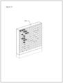
- This figure presents the component elements of the plant biological filtering device in a configuration sustained on an existing wall or support, clearly showing the movement of the flow of gases.
- the figure on the right presents the configuration of the plant biological filter when it is selfsustained showing the tubes that distribute the gas internally and that are part of the inferior plenum.
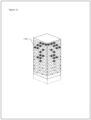
- This figure presents the component elements of the plant biological filtering device, in a self-sustained configuration in the same structure of the biological filter, where the moment of the flow of gases can be seen clearly.
- This figure presents two photographs, the upper photograph presents the decontamination system operating for three months and the growth of the plants associated to the biofilter.
- the lower photograph presents the biofilter alone, filtering environmental air, not connected to the decontamination system.
- the device was connected using an extraction coupling (4) at the gas outlet (2) from a double combustion Heater (1) of 8.8 kW, the measurement in kW refers to the original source of fume emissions, a product of biomass combustion among others.
- Wood with a humidity equal to or of less than 17% was used for executing the tests, although this invention is not limited with regard to the humidity of the fuel.
- the total journey of the fumes via the ducts is 14m.
Landscapes
- Engineering & Computer Science (AREA)
- Chemical & Material Sciences (AREA)
- Chemical Kinetics & Catalysis (AREA)
- Environmental & Geological Engineering (AREA)
- Health & Medical Sciences (AREA)
- Biomedical Technology (AREA)
- Life Sciences & Earth Sciences (AREA)
- Analytical Chemistry (AREA)
- General Chemical & Material Sciences (AREA)
- Oil, Petroleum & Natural Gas (AREA)
- Molecular Biology (AREA)
- Biodiversity & Conservation Biology (AREA)
- Ecology (AREA)
- Forests & Forestry (AREA)
- Environmental Sciences (AREA)
- Combustion & Propulsion (AREA)
- Mechanical Engineering (AREA)
- General Engineering & Computer Science (AREA)
- Botany (AREA)
- Filtering Of Dispersed Particles In Gases (AREA)
- Separation Using Semi-Permeable Membranes (AREA)
- Medicines Containing Plant Substances (AREA)
Description
- Decontamination system by extraction, cooling and filtering of fumes, adaptable to any combustion system of biomass and coal, that reduces the amount of particulate matter issued into the atmosphere.
- This development refers to the use of a plant Biofilter to retain and treat the particulate matter contained in the gases coming from coal and biomass combustion devices, hereinafter "fumes". It consists mainly of a support structure, ducts, fume impulsion and extraction mechanisms, cooling system, plant material and organic elements used for the retention of particulate matter.
- At present there are plant biofilter systems for the decontamination of the air.
- The first biofilter to mention is a decontamination system for ambient air; when the air is guided through a substrate populated by microorganisms the pollutants present in the contaminated air become fixed and are degraded by the microorganisms inside the substrate layer.
- This is a purification method for contaminated air, with a layer of soil that permits the passage of the air and with the possibility of cultivating plants in this substrate layer.
- This invention (
GB 2 297 097 A - There is another patent of plant walls with internal circulation of air (
WO 2012/085439 A1 ). This system is made up of superposed metal structures, obtaining a continuous substrate between these cells with networks of irrigation ducts and of air ducts within the plantation substrate. The air distribution network permits the circulation of the contaminated air, interior or exterior, driven by a ventilator to decontaminate this air once it encounters the substrate by a filtering effect to which the bacterial action is added according to the principle of the biofilter. This air distribution network, placed vertically within each cell consists, at least, of an air distribution plenum connected to a forced-air supply duct. This plenum must have an air diffusion window or grille in one of its two faces. - In both cases, the purpose or technical problem is filtering ambient air charged in atmospheric pollution. The end purpose of each one of these inventions is to decontaminate the air found in the atmosphere, guiding it through a plant biofilter through a ventilation system.
- The purpose of this innovative development is to filter contaminated air generated by wood-burning stoves and fireplaces, without restricting it to these fumes only, connecting the ventilation system directly to the duct thereof. Therefore, the ventilation system must be able to move a volume of contaminated air that is greater, and has more pressure and flow than the above-described systems. Moreover, in the case of hot fumes, the device must contain a fume cooling system to be able to reach the plant biofilter at an adequate temperature and thus permit the growth of the plants and facilitate an optimum action of the microorganisms.
- The system proposed is based on a derivation of the Patent (
WO2012085439 ) GREEN WALL HAVING INTERNAL AIR CIRCULATION. The green wall consists of a structure made up of juxtaposed and/or superposed boxes; each box has a frame that supports a textile fabric or rigid plates. The boxes are filled with a planting substrate for the plants that grow on their front faces, at least. An air distribution network connected to a pump supplies air through the thickness of the boxes, and therefore, in the interior of the planting substrate. This network, placed vertically within each box, consists of an air distribution chamber connected to a forced-air supply duct, the impelling or plenum chamber has an air diffusion window or grid. The invention is applied to the production of a green wall for the decontamination of atmospheric air. - The vegetated walls in which the decontaminating system has been incorporated refer to the
European Patent EP 1 771 062 B1 STRUCTURE FOR VEGETATED WALL. This invention is about a light, self-supporting wall with vegetation composed mainly of prismatic shaped boxes designed to be mounted juxtaposed and/or stacked. Each box includes lattice or mesh surfaces aligned internally and they are filled with a planting substrate. A network of water pipes and air outlets can be incorporated into the thickness of the structure, those networks pass through the separation lines between the boxes. The structure is designed for urban improvements, and to produce acoustic screens, partitions, billboards and the like. The advantage of a vegetated wall structure of this type is its modular nature that makes it easier to transport and install, while at the same time permitting its adaptation to each case of application and that it does not need to be fixed to a support wall. Moreover, it can easily be equipped with an internal irrigation network that can pass through the connection surfaces between adjacent compartments whether the faces are latticed or perforated in another way.WO 2012/085439 A1 andGB 2 297 087 A - The issue then raised is the possible utilization of the Vegetated Wall (
European Patent EP 1 771 062 B1 ) as a plant Biofilter (WO2012085439 ) adapted to filter combustion fumes. We shall define combustion fumes as the fumes generated by the combustion of biomass, coal, petroleum derivatives, pellets, among others. Specifically, the combustion sources that use fuels of plant origin (wood 25% humidity, pellets and the like) are of particular interest. The system functions by receiving and filtering fumes by means of fume ducts, cooler, extractor and impeller to an injection plenum (*), and then through a vegetated wall substrate, to retain and filter the particulate matter and the pollutants. - (*) The injection plenum is a closed space where air or other gases are stored at low speeds. The result of the design of this chamber is that the pressure of the gas introduced is distributed equally throughout the system's entire inner surface.
- The essential features of the invention are explicitly defined in the wordings of
independent system claim 1 andindependent process claim 15 on file. Additional embodiments of the invention are explicitly defined in the wordings of dependent claims 2-14 and 16-20 on file. This system is defined in that it consists of seven devices (A to G) interconnected sequentially for its operation. The process whereby it operates is also defined within the system. - This system includes : (A) The connection (4) of the fume extraction device to the combustion system, Then, following the direction of the system, we have the conduction device (B) that contains tubular section ducts, which conduct the hot air over the cover. These elements, separated from the cover, are anchored to the cover structure and they are sealed in each one of the unions to avoid seepages through the interstices and thus reduce the loss of flow on the way. This device also has registration elements. Following the path of the gases is the cooling device (C) where the fumes emitted by the wood combustion system travel via circular section ducts to enter the cooler, formed by tubular elements having a rectangular section smaller than that of the extraction tubes, so that the sum of the surface of its sides will be greater than the sum of the surfaces of the conveyance ducts, thus managing to reduce the temperature of the fumes by increasing the dissipation surface. On the other hand, the number of ducts, length and area of each section of the cooler is related in direct proportion with the distance to the capture point of the fumes. After cooling the gases, comes the suction device (D) that collects the fumes, which are at a low temperature due to the action of the coolant, suctioning them via an electro-mechanical system that increases their pressure and flow. The extractor of the suction device is regulable and is in direct proportion to the distance to the capture point of the fumes, height, diameter of the ducts and distance from the cooler (9). Subsequently the gases coming from the cooler are received and conveyed in induction device (E) that corresponds to a box that includes circular ducts of a smaller diameter to increase the speed of the gases towards the injection plenum and thus to the plant biofilter. The process of transferring from the drive box is executed by means of ducts that have a
section 1/10 of the path's duct (5, 8 and 10) which increases the injection speed into the plenum in 140%. The plenum (F) corresponds to a closed space where the fumes concentrate to be distributed uniformly in the plant biofilter. The pressure of the fumes introduced is stored in its entire internal surface and are incorporated constantly into the plant biofilter. Finally, in this circuit we find the plant biofilter (G) where the fumes, when distributed uniformly in the substrate, are filtered and freed of suspended particles. All this sequence of devices can be seen clearly infigure 1 /13. - The plenum (F) applied for the system has three possible configurations:
When the biofilter is self-sustaining, the configuration used is a lower plenum (figure 11 /13). - When the biofilter is supported by a wall or another surface, there are two configurations, the side plenum and the lower plenum (
figure 9 /13). - For the biofilter to be able to respond to the offer of highly concentrated and contaminated material, a minimum surface (biofilter) and flow (fumes) relationship is required that is not described in the patent where the base structure for the treatment of atmospheric air (with highly diluted atmospheric contamination in comparison with that produced in a fireplace) is developed. This relationship of 390 m3/hour for every m3 of biofilter in the system was obtained in tests described later in the specification.
- On the other hand, the filtering of the fumes requires reaching a biologically acceptable temperature. The fumes leave the duct at a temperature between 160 °C and 250 °C and reaches the biofilter at a temperature between 10 °C and 40 °C.
- On the other hand, this development seeks to protect the fume purification process itself. To do this, the process is divided into various stages:
- i) Capture process;
- ii) Conveyance;
- iii) Cooling;
- iv) Momentum and injection; and
- v) Plant filtration.
- The fume capturing stage (i) is executed via a coupling (4), that, because of its design, splits the fumes and does not interfere in the normal operating process of the artefact that executes the combustion. In the second stage, conveyance (ii), the fumes travel and are conveyed at a constant speed, staying in ducts with regular sections (5, 8 and 10), respectively with direction breaks by means of T-registers (6) and register covers (7). The third stage, cooling (iii), takes place via a cooler (9). Here the fumes are distributed in as many sections as may be required to lower the temperature from 250°C to 10°C (so that the fumes are biologically suitable). The sum of the smaller sections is greater than that of the duct (5, 8 and 10); therefore, the travel speed is reduced in each section and as a result the time the fumes remain in an area of greater dissipation increases and, therefore, the temperature of the fumes drops without varying the flow per hour of the route. The number of ducts, longitude and area of each section of the cooler (9) is related in direct proportion to the distance to the point of capture (4) of the fumes. Because in this process the regulable (15) extractor (14) is in direct proportion to the distance to the point of capture (4), altitude, diameter of the ducts and distance from the cooler (9), the process it carries out is to balance, compensate and maintain the natural flow of the combustion system installed. At the same time, we have the fourth stage of the process, momentum and injection (iv), where the extractor (14) drives the gases to an injection box (16) that has a volume equivalent to one fourth of the cooler (9), and feeding at a constant speed increases the density of the air confined. The transfer process from the drive box (16) is carried out by means of ducts that have a
section 1/10 of the travel duct (5; 8 and 10), which increases the injection speed into the plenum (19) in 140%. Finally, there is the fifth stage (v) of plant filtration where the use of a plant wall such as the one described inEuropean patent EP 1 771 062 B1 is preferable. It should be noted that this development is not limited by the only forms of execution of this vegetated wall structure that have been described previously as an example; on the contrary, this one includes all the implementation and application variants that respect the same principle. - The plant filtration stage (v) does not produce waste, it absorbs and recycles the pollutants. This because part of the gases like carbon monoxide and dioxide acidify the irrigation water producing carbonic acid, which in turn improves the plants' capacity to absorb nutrients. Waste with products derived from sulfur and nitrogen are absorbed rapidly by the biofilter's roots improving plant growth, without an increase in water consumption. This is clearly visualized in figure 13/13.
- Some specifications for the optimum operation of the system are:
Between points (4) and (14), with the purpose of maintaining efficiency, the tube distances range between 8 and 25 meters. - Between points (14) and (19), with the purpose of maintaining efficiency, the tube distances range between 0.2 and 7 meters.
- On the other hand, the whole system works integrating the devices through a process linked to the previous and posterior element, that is, the interactions of the different devices are necessary so that the result of the total process takes place.
- In general, the variables of gas temperature, flow and fuel used are relevant for the design and efficiency of the device. The result is a high efficacy in the fume filtering process with a greater percentage of retention of the polluting agents.
- Particularly, they will not deviate from the scope of the invention, modifying details of its elements or resorting to other connection means and attachment of its elements, or employing other materials, or even adding particular accessories or provisions.
- The technical problems that it is hoped this system will resolve are:
- Achieve the reduction of the polluting particles originating from the fumes using a plant biofilter.
- Achieve the dissipation of the fume temperature to be able to come into contact with a plant biofilter without destroying it.
- Obtain a fume flow plant biofilter surface ratio that is efficient in the retention of fume particles.
- Improve the growth of the plants of the biofilter by the concentrated entry of carbon-based nutrients (fumes).
- Acidify the biofilter's substrate to better release nutrients from the plants it is made up of.
- Filter the fumes produced with this system, with a minimum operative maintenance of same.
- Obtain a process whereby the particles of the fumes can be removed with a minimum maintenance and in a manner that is environmentally friendly.
- This figure represents a sketch of the system of this invention composed of seven devices according to
figure 1 /13. - A: extraction device
- B: Conveyance device
- C: Cooling device
- D: Suction device
- E. Induction device
- F: Injection plenum and
- G: Biological plant filtering device for the gases
- This figure presents a gas flow chart and its operation in the complete system. Also, the biofilter presented is one of the forms of execution of the vegetated wall structure without restricting it only to this.
- In general, this figure also presents the fundamental parts of the different devices that make up the system and some necessary parts, outside the system, for an understanding of the system as a whole:
- (1) Heater: refers to the original source of fume emissions, produced by the combustion of wood, pellets or the like.
- (2) Gas outlet duct: refers to the outlet duct for the heater (1) that conveys the fumes towards the exterior of the premises and in its final section will be intervened by the extraction joint (4) so as to generate an alternative fume conveyance path towards the plant biofilter.
- (3) Protection of the outlet duct: allows the correct exit of the fumes towards the exterior and protects the entire system (1 and 2) from the entry of water and other harmful elements.
- The system itself consists of the following elements:
- (4) Extraction connection: It is a T-shaped connector that creates a bifurcation to permit a flow of fumes, alternative to the original one. It consists of two intersected cylindrical ducts. The first duct maintains the continuity of the fume outlet duct (2), and must have the same diameter and be coupled correctly without seepages; the second duct conveys the fumes towards the plant biofilter. The extraction connection (4) can have a smoke sensor that activates the extractor (14) to start the system automatically.
- (5) Conveyance Element: consists of a cylinder that conveys the fumes towards the T-register (6) (gas derivation element) before the cooler, wherein there is a register cover (7) before the cooler: The T-register and the register cover, together, allow a change in direction of the conveyance of fumes in (5) and (8) and also the inspecting and cleaning of the section.
- (8) The conveyance element prior to the cooler: conveys the gases from the T-register (6) towards the cooler (9).
- (9) The cooler: refers to a sealed element with only one input opening and another outlet for the gases. It consists of a connection to the duct (8) and a derivation to a series of ducts having a rectangular section that separate and divide the flow of fumes with the purpose of reducing their temperature. In the final section of the element, regarding the direction in which the fumes advance, this group of ducts comes together again in a single rectangular-shaped chamber to become coupled, at a single point, to the duct (10).
- Duct (10) after the cooler: conveys the gases from the cooler (9) towards the T-register (11). The T-register (11) after the cooler consists of two intersected ducts. Combined with the register cover (12) after the cooler, they permit a change of direction in the conveyance of fumes (10) towards the flange (13) and also inspect and clean the section.
- (12) Register cover after the cooler.
- (13) The flange is the element that joins the T-register (11) with the extractor (14), allowing the dismantling of the latter without destructive operations, thanks to a circumference of perforations through which the stitch bolts are mounted.
- (14) The extractor is an electro-mechanical equipment that suctions the gases coming from the heater (1) to drive them towards the plant Biofilter (18). Its action is controlled by means of a flow regulating electronic device (15). The extractor (14) is connected directly to the drive box (16).
- (15) Electronic device that regulates flow.
- (16) The drive box: consists of a sealed box with only one entry opening and a gas exit, it receives fumes and conveys them to the injection plenum (19) by means of conveyance elements (17).
- (17) Conveyance elements: these are ducts that maintain the adequate pressure and flow for the entry of the fumes into the injection plenum (19), they are regulated manually by injection regulators (18).
- (18) Injection regulators: these regulators control the flow that enters the injection plenum.
- (19) The injection plenum: refers to a sealed chamber with an opening for the gas to enter and open on the side that connects with the plant Biofilter (20). The pressure of the gases that are introduced is spread equally throughout its internal surface and is integrated to the substrate in a constant manner.
- (20) Plant Biofilter: this is a green wall that acts as a biological filter like the one described in
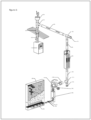
European patent EP 1 771 062 B1 . This does not limit the existence of other spatial arrangements, for example, self-supported, without leaning against a wall where they could be applied as a biofilter. What is substantial is to maintain a certain verticality of the biofilter so that the fumes will travel over a greater area of it. - This figure presents the component elements of the extraction device where the movement of the flow of gases can be seen very clearly.
- The numbers indicated in the figure are presented below:
- (2) gas outlet duct
- (3) protection of the outlet duct
- (4) extraction coupling
- (5) duct
- This figure presents the component elements of the conveyance device where the movement of the flow of gases can be seen very clearly.
- The numbers indicated in the figure are presented below:
- (5) duct
- (6) T-register before the cooler
- (7) register cover before the cooler
- (8) duct before the cooler
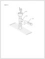
- This figure presents the elements that are components of the cooling device where the movement of the flow of gases can be seen clearly.
- The numbers indicated in the figure are presented below:
- (8) The duct to the cooler
- (9) The cooler
- (10) duct after the cooler.
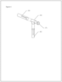
- This figure presents the elements that are components of the suction device, clearly showing the movement of the flow of gases.
- The numbers indicated in the figure are presented below:
- (10) duct after the cooler.
- (11) The T-register after the cooler.
- (12) Register cover after the cooler
- (13) The flange
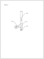
- This figure presents other elements that are components of the suction device, clearly showing the movement of the flow of gases.
- The numbers indicated in the figure are presented below:
- (13) The flange
- (14) The extractor
- (15) Electronic device that regulates the flow.
- This figure presents the elements that are components of the induction device where the movement of the flow of gases can be seen clearly.
- The numbers indicated in the figure are presented below:
- (16) The drive box
- (17) Conveyance elements
- (18) Injection regulators
- The figure on the upper left presents the component elements of the injection plenum, clearly showing the movement of the flow of gases.
- The figure on the upper right presents the configuration of the biofilter supported on a structure that already exists; therefore, the plenum also presents a lower injection configuration, where the gases are distributed in the biofilter through the plenum's inner channels.
- The inferior figure shows the second configuration of the plenum when the biofilter is sustained on an existing structure, where the position of the plenum is lateral and distributes the gases through a fabric especially suitable for these purposes.
- The numbers indicated in the figure are presented below:
- (19) The injection plenum
- (21) Inner channels of the plenum
- (22) Gas distribution fabric
- This figure presents the component elements of the plant biological filtering device in a configuration sustained on an existing wall or support, clearly showing the movement of the flow of gases.
- The number indicated in the figure is presented below:
(20) Plant biofilter - This figure presents, on the left, the component elements of the injection plenum, when the configuration of the plant biological filter is selfsustained with an inferior plenum, where the movement of the flow of gases can be seen very clearly.
- On the other hand, the figure on the right presents the configuration of the plant biological filter when it is selfsustained showing the tubes that distribute the gas internally and that are part of the inferior plenum.
- The number indicated in the figure is presented below:
- (19) injection plenum
- (21) Inner channels of the plenum
- This figure presents the component elements of the plant biological filtering device, in a self-sustained configuration in the same structure of the biological filter, where the moment of the flow of gases can be seen clearly.
- The number indicated in the figure is presented below:
(20) Plant biofilter - This figure presents two photographs, the upper photograph presents the decontamination system operating for three months and the growth of the plants associated to the biofilter.
- The lower photograph presents the biofilter alone, filtering environmental air, not connected to the decontamination system.
- To prove the efficiency of the device, five pilot plants with similar characteristics and different measurements were installed. One of these pilot plants was taken as a reference, according to the following characteristics: the device was connected using an extraction coupling (4) at the gas outlet (2) from a double combustion Heater (1) of 8.8 kW, the measurement in kW refers to the original source of fume emissions, a product of biomass combustion among others.
- Wood with a humidity equal to or of less than 17% was used for executing the tests, although this invention is not limited with regard to the humidity of the fuel.
- The total journey of the fumes via the ducts is 14m.
- The system employed consists of:
- An extraction coupling (4) that branches the fumes, installed at 6.00m between the end of the gas outlet duct (2) and the outlet duct protection element (3).
- It is conveyed above the 6 meters of duct (5) from the T coupling or bifurcation to the T register of section (6) and from this element by conveyance (8) five meters to the entry of the cooler (9), of 3m2 of dissipation surface and three routes.
- The suction of the cooler's fumes (9) was executed by a medium pressure and simple aspiration centrifugal fan with housing and turbine with maximum flow of 1691 m3/h (14) and compressed in the drive box (16) of 0.04 m3 volume. The flow of the regime registered during the tests was 311 m3/h.
- From the drive box (16), the fumes were injected into the 0.8 m3 plenum, whose function is to distribute homogeneously the entry of the fumes into the biofilter, in this case a 4 m2 and 20 cm thick green wall.
- Acidification of the substrate of the biofilter helping the liberation of nutrients towards the plants of the biofilter.
- Improvements in the growth of the biofilter' s plants maintaining the same amount of irrigation water.
-
Table I: System MFB 01 Type E20 Location: Nahuelbuta Street 2047, Temuco Dimension: Biofilter 2.00 x 2.00 0.20 m Volume: Biofilter 0.8 m3 Extraction length: 14.00 m Diameter of ducts: Galvanized Ø 15.24 cm Radiator: Galvanized 3.2 m2 area of dissipation Heater model: without brand, double chamber type. Slow combustion. Extractor model: Medium pressure and simple aspiration centrifugal fan with housing and turbine. Maximum flow: 1691 m3/h Flow regime: 311 m3/h Sampling speed: 1.2 m/s Injection to plenum: Independent, one per c/m2 Total volume plenum: 0.8 m3 Screen: Stainless steel mesh 300 micras Biofilter: inert plant fiber Fuel: Wood % Humidity: 17% - The experimental results observed during this test, according to the CH5 method (method used under Chilean rules to make measurements in fixed sources of gases) for determining the emissions of particles from stationary sources, were the following:
-
PARAMETER C3 C4 C average D DATE 13-07-15 13-07-15 TIME 13:40 15:00 14:53 16:14 Conc. of Particulate Matter (mg/m3N) 652.40 432.48 542.44 155.51 Corrected Conc. Particulate Matter (mg/m3N) 652.40 432.48 542.44 155.51 Hourly issuance 0.20 0.14 0.17 0.05 Standardized gas flow (m3N/h) 314 314 314 0 Excess of air (%) % O2 19.0 17.8 18.4 0.9 % CO2 1.7 1.7 1.7 0.0 ppm CO 3379.0 6000.0 4689.5 1853.3 Isokinetism (%) 96.9 97.8 97.4 0.6 Humidity of the gases (%) 1.2 1.3 1.3 0.1 Speed of the gases (m/s) 1.19 1.19 1.19 0.00 Temperature of the bases (°C) 9.3 9.6 9.5 0.2 -
PARAMETER C1 C2 C average D DATE 13-07-15 13-07-15 TIME 10:40 12:05 11.54 13:19 Conc. of Particulate Matter (mg/m3N) 53.95 16.94 35.44 26.18 Corrected Conc. Particulate Matter (mg/m3N) 53.95 16.94 35.44 26.18 Hourly issuance 0.02 0.01 0.01 0.01 Standardized gas flow (m3N/h) 314 313 313 1 Excess of air (%) % O2 20.0 19.0 19.5 0.7 % CO2 0.0 1.7 0.9 1.2 ppm CO 6000.0 4000.0 5000.0 1414.2 Isokinetism (%) 99.6 96.9 98.3 1.9 Humidity of the gases (%) 1.3 1.1 1.2 0.1 Speed of the gases (m/s) 1.20 1.20 1.20 0.00 Temperature of the bases (°C) 10.9 11.8 11.3 0.6 Performance Biofilter N° 1 = 93.47%
Date: 13 July 2015
Address: Nahuelbuta 2047
(*) Final results - The results of these tests clearly indicate a performance greater than 90%, preferably 93.47%, where the reduction of different emissions was achieved and especially the particulate material.
- In general, the results of five of the experiments gave a range of efficiency in particulate material retention of between 72 to 95%.
- The flow of filtered fumes operative in the different tests goes from 300 m3/h to 500 m3/h; these flow values do not restrict the current development.
- An interesting result is the relationship that each 390 m3/h flow in regime of fumes requires 1 m3 of biofilter and was confirmed for the range between 216 to 512 m3/h of flow in regime of smoke with an equivalent range of biofilter volume between 0.55 to 1.32 m3 to achieve a filtering with an efficiency above 90%. These values are not restrictive to other flows in which the system could be applied.
- A second experiment demonstrated the efficiency in the growth of the biofilter depending on the injection of the fumes from the combustion devices (figure 13/13).
- The fumes coming out of the chimney had a flow of 390 m3/h in regime. On the other hand, the experiment was carried out for three winter months.
- In this experiment, a biofilter was used, mounted on a wall with a volume of the same m3, with a lateral injection plenum. On the other hand, the amount of water used was one m3.
- One of the phenomenon detected in this test was the rapid acidification of the soil by the generation of carbonic acid when the carbon monoxide of the products derived from the combustion came into contact with the irrigation water. This phenomenon causes the roots to be more exposed to the absorption of nutrients necessary for their growth.
Claims (20)
- A fume decontamination system connectable to any combustion system, characterized in that it includes seven devices (A to G) interconnected sequentially as follows:- (A) The connection (4) of the fume extraction device to the combustion system,- (B) A conducting device comprising ducts (5,8),- (C) A cooling device comprising a cooler (9), the cooled fume is conducted to a suction device (D) through ducts (10,11)- (D) The suction device, which includes an extractor (14) and an electronic device (15) for regulating the flow thereof, the suction device drives the pressurized fumes to an induction device (E),- (E) the induction device (E) comprises a drive box (16), conveyance elements (17 ) and injection regulators (18) , the induction device concentrates and directs the fumes to a plenum unit, (F),- The plenum unit (F) comprises an injection plenum (19) and injection channels (21), and- (G) A biological plant filtering device comprising a biofilter substrate, WHEREIN: The injection plenum channels (21) uniformly distribute the fume in the plant biofilter substrate at different levels of the biofilter substrate to homogenize the entry of fumes to the biofilter substrate and ensure that the fume travels evenly through the biofilter substrate.
- A fume decontamination system according to claim 1, in combination with a combustion system, CHARACTERIZED in that the fumes are generated with any biomass material, regardless of its level of humidity.
- A fume decontamination system according to claim 1, in combination with a combustion system CHARACTERIZED in that the fumes are generated with coal.
- A fume decontamination system according to claim 1, in combination with a combustion system CHARACTERIZED in that there is no need to intervene the operation of the combustion system installed, because the fumes are taken at the point of exit to the atmosphere.
- A fume decontamination system according to claim 1, CHARACTERIZED in that it adjusts for automatic regulation according to the flow of fumes thus avoiding an increase of fuel consumption due to more suction.
- A fume decontamination system according to claim 1, in combination with a combustion system CHARACTERIZED in that the ratio between the flow of fumes generated in regime versus the amount of biofilter necessary to achieve filtering between 72 to 95% of contaminant particles comprises a range of 216 to 512 m3/h of fumes generated in regime for a range of 0.55 to 1.32 m3 of biofilter volume, preferably every 390 m3/h flow rate of fumes requires 1 m3 of biofilter to achieve a filtering with an efficiency over 90%.
- A fume decontamination system according to claim 1, in combination with a combustion system CHARACTERIZED in that the extraction device (A) comprises:(2) gas outlet duct;(3) protection of the outlet duct;(4) extraction splice; anda duct (5), which is as a guide element,where elements (2) and (3) are part of the combustion system and elements (4) and (5) are the connection of the fumes to the decontamination system wherein the element (4) branches the fumes thus achieving non-interference in the normal process of operation of the artifact that performs the combustion.
- A fume decontamination system according to claim 1, CHARACTERIZED in that the conducting device (B) is connected via the duct (5) and comprises:a T-register (6) before the cooler;a T-register cover (7) before the cooler,
anda duct (8) before the cooler, where the elements that are separated from the roof are anchored to the roof structure and sealed in each of the joints to prevent leakage through the gaps, thereby reducing flow losses along the way. - A fume decontamination system according to claim 8, CHARACTERIZED in that the T-register (6) before the cooler (9) J can be open or closed for the cleaning and monitorization of the duct.
- A fume decontamination system according to claim 1, CHARACTERIZED in that that cooling device (C) is connected 5 through duct (8) before the cooler (9)
and consists of:The cooler (9);and the duct (10) following the cooler (9),wherein the cooler (9)is formed by tubular elements of rectangular section of smaller section than the extraction elements, so that the sum of the surface of its sides is greater than the sum of the surfaces of the conveyance ducts thus managing to decrease the temperature of the fumes by increasing the dissipation surface. - A fume decontamination system according to claim 1, CHARACTERIZED in that the suction device (D) is connected through the conducting member behind the cooler (10) and consists of:a post-cooler T register (11),a post-cooler register cover (12);a flange (13) ;the extractor (14) andan electronic flow control device (15),wherein the fumes at low temperature are collected and are suctioned by the extractor (14) which is an electro-mechanical equipment which increases the pressure and flow rate thereof, on the other hand, the extractor (14 ) is adjustable and controlled by the electronic flow control device (15) and is in direct proportion to the distance to the point of capture of the fumes, height, diameter of the ducts and distance from the cooler (9).
- A fume decontamination system according to claim 1, CHARACTERIZED in that the induction device (E) is connected through the extractor (14) and consists of:(16) a drive box;(17) conveyance elements; and(18) injection regulators, wherein the drive box (16), for its part, consists of ducts of circular section of smaller diameter than the housing to thus increase the speed of the gases towards the plenum (F) and thus to the plant biofilter (G), where the transfer process from the drive box is performed by means of ducts that have section 1/10 of the duct of the route covered in the elements (5, 8 and 10), which increases the injection speed to the plenum (F) by 140%.
- A fume decontamination system according to claim 1, CHARACTERIZED in that the plenum (F) consists of at least three configurations, the first with a lower plenum disposed below the biofilter that is based on an existing support, such as a wall, the second with the same type of biofilter supported on a surface such as a wall, but with a plenum placed laterally to the biofilter, where a fabric is placed that distributes the fumes evenly (22), and the third where the biofilter is self-supporting only using the injection plenum as a basis, like a totem, where in the first and third cases the injection plenum comprises perforated channels (21) inside the biofilter.
- A fume decontamination system according to claim 1, CHARACTERIZED in that the biological plant filter device (G) is connected via the injection plenum (F) and comprises:(20) plant biofilter,wherein the biofilter comprises at least two configurations, the first where the biofilter is supported on an existing support, such as a wall and the second where the biofilter is self-sustaining, as a totem, without excluding other forms of support of the biofilter.
- A fume decontamination procedure using the fume decontamination system according to claim 1 connected to any combustion system, CHARACTERIZED in that it consists of
the steps of:i) capturing the fumes via a branching (4), whose design causes the bifurcation of the fumes and does not interfere in the normal operating process of the artifact that performs the combustion;ii) guiding the fume, where the fume travels and is driven at a constant speed and stays in ducts with a regular section (5, 8 and 10), in breaks of direction (6) and through registration elements (7);(iii) cooling the fumes, where the fumes are distributed over as many sections as required in the cooler (9), where the temperature is lowered in a range from 250 °C to 10 °C, where the flow of fumes decelerates because the sum of the lower sections of the cooler is greater than that of the inlet duct (5, 8 and 10); due to the above, the travel speed is decreased in each section and consequently there is an increase in the time the fumes remain in a larger dissipation area and therefore, the temperature of the fumes drops, without varying the flow per hour of travel; on the other hand, the electronic regulating device (15) for regulating the flow of the extractor (14) balances, compensates and maintains the natural flow of the combustion system installed;iv) drive and injection, wherein the extractor (14) drives the fumes to the drive box (16) and feeds at a constant speed, thereby increasing the density of the confined air, where the transfer from the drive box (16) is performed through ducts having a 1/10 section of the travel duct (5, 8 and 10), which increases the injection speed into the plenum (19) in 140% and the latter injects the fumes in the last stage of the process; andv) plant filtration, where the particulate material of the fumes is filtered, preferably using a vertical wall of vegetation substrate, supported or self-supported, where what matters is that the fumes travel the larger contact surface with the plant filter substrate. - A fume decontamination procedure
according to claim 15, CARACTERIZED in that the stages of guiding (ii) and driving and injection (iv) are monitored and cleaned through their respective registers and register covers. - A fume decontamination procedure according to claim 15, CARACTERIZED in that the plant filtration stage (v) has a particle filtration capacity in the range below 2.5 parts per million up to 10 parts per million as final filtering.
- A fume decontamination procedure according to claim 15, CHARACTERIZED in that the drive and injection stage (iv) regulates the flow of fumes through the extractor (14) that receives flow orders from the electronic flow regulator device (15).
- A fume decontamination procedure according to claim 15, CHARACTERIZED in that the fume cooling stage (iii) manages to reduce the temperature of the fumes so that they can be used by the biofilter, from temperatures close to 250 °C to temperatures close to 10 °C.
- A fume decontamination procedure according to claim 15, CHARACTERIZED in that the plant filtration stage (v) does not produce waste, absorbing and recycling the pollutants.
Applications Claiming Priority (2)
| Application Number | Priority Date | Filing Date | Title |
|---|---|---|---|
| CL2015002478A CL2015002478A1 (en) | 2015-09-04 | 2015-09-04 | Decontamination system through a biofilter to retain and recycle contaminants of particulate material from combustion fumes; and its procedure. |
| PCT/CL2016/000052 WO2017035678A1 (en) | 2015-09-04 | 2016-09-09 | Systems for decontamination by means of a biofilter for retaining and recycling pollutants of particulate material from combustion fumes, and method thereof |
Publications (4)
| Publication Number | Publication Date |
|---|---|
| EP3345671A1 EP3345671A1 (en) | 2018-07-11 |
| EP3345671A4 EP3345671A4 (en) | 2019-05-29 |
| EP3345671C0 EP3345671C0 (en) | 2023-07-19 |
| EP3345671B1 true EP3345671B1 (en) | 2023-07-19 |
Family
ID=56081052
Family Applications (1)
| Application Number | Title | Priority Date | Filing Date |
|---|---|---|---|
| EP16840490.3A Active EP3345671B1 (en) | 2015-09-04 | 2016-09-09 | Systems for decontamination by means of a biofilter for retaining and recycling pollutants of particulate material from combustion fumes, and method thereof |
Country Status (6)
| Country | Link |
|---|---|
| US (1) | US11202990B2 (en) |
| EP (1) | EP3345671B1 (en) |
| CL (1) | CL2015002478A1 (en) |
| ES (1) | ES2957218T3 (en) |
| MX (1) | MX2018002582A (en) |
| WO (1) | WO2017035678A1 (en) |
Families Citing this family (2)
| Publication number | Priority date | Publication date | Assignee | Title |
|---|---|---|---|---|
| CN110369440A (en) * | 2019-06-26 | 2019-10-25 | 安徽安江环保科技有限公司 | A kind of combustion refuse flying dust recovery process |
| CN113090358B (en) * | 2021-05-25 | 2022-08-05 | 福建恒冠机电设备有限公司 | Environment-friendly diesel generating set |
Family Cites Families (19)
| Publication number | Priority date | Publication date | Assignee | Title |
|---|---|---|---|---|
| US4070300A (en) * | 1973-06-09 | 1978-01-24 | Collo Gmbh | Pourable solid filter material, particularly for the removal of unpleasant odors from the air, and a process for its manufacture |
| SE406425B (en) * | 1974-05-17 | 1979-02-12 | Smit Nijmegen Bv | PROCEDURE AND ARRANGEMENT FOR PRODUCING INERT GAS |
| US4163430A (en) | 1978-02-08 | 1979-08-07 | Neumann Siegmar R | Heat recovery and filter system and process for furnace exhaust gases |
| CA1241524A (en) * | 1985-01-21 | 1988-09-06 | Hyman D. Gesser | Abatement of indoor formaldehyde vapour and other indoor gaseous pollutants |
| US5397382A (en) * | 1993-10-18 | 1995-03-14 | Alliance Research And Manufacturing Corporation | Bio regenerating air filter |
| JP3419939B2 (en) * | 1995-01-19 | 2003-06-23 | 株式会社フジタ | Air purification soil unit and method for purifying contaminated air using air purification soil unit |
| US6006471A (en) * | 1998-05-07 | 1999-12-28 | Sun; En-Jang | Air-cleaning ecosystem apparatus |
| US6117672A (en) * | 1998-12-22 | 2000-09-12 | Breckenridge; Leon | Moving bed biofilter and condenser for flue gas pollutant removal and collection |
| WO2002053977A1 (en) * | 2000-12-29 | 2002-07-11 | Transform Af 1994 Aps | A biological filter system and a housing for a biological filter system |
| JP4124584B2 (en) * | 2001-10-01 | 2008-07-23 | 新日鉄エンジニアリング株式会社 | Removal method of dioxins in exhaust gas from waste treatment furnace |
| WO2004085032A2 (en) * | 2003-03-24 | 2004-10-07 | Valerio Abate | Method and device for pollution reduction from exhausts emissions |
| US7587858B2 (en) * | 2005-08-11 | 2009-09-15 | Roy E. Hock | Method and apparatus for cultivation of subaquatic vegetation |
| EA014126B1 (en) * | 2006-06-15 | 2010-10-29 | Экокат Ой | COATING FOR FILTER FOR COLLATING PARTICLES |
| WO2012067356A2 (en) * | 2010-11-17 | 2012-05-24 | 그린인프라 주식회사 | Pot for vertical wall, and multi-filter and port support frame used therefor |
| FR2968891B1 (en) * | 2010-12-20 | 2012-12-28 | Canevaflor | VEGETABLE WALL WITH INTERNAL CIRCULATION OF AIR |
| US8945248B2 (en) * | 2011-06-09 | 2015-02-03 | General Electric Company | Biofilter assemblies for biomass gasification systems |
| JP6331248B2 (en) * | 2012-01-16 | 2018-05-30 | パナソニックIpマネジメント株式会社 | Plant growing device |
| CL2012000396A1 (en) * | 2012-02-15 | 2012-08-31 | Albornoz Victor Aldo Romero | Gas purifier system, traps and recycler of particles coming from internal combustion engines, which is composed of three individual bodies, the first body "a" is a cooling chamber, body "b" is a recycler silencer, and the body "c" is a gas purifying tank. |
| TWM481375U (en) * | 2014-02-19 | 2014-07-01 | zhen-xin Lin | Air cleaning device |
-
2015
- 2015-09-04 CL CL2015002478A patent/CL2015002478A1/en unknown
-
2016
- 2016-09-09 MX MX2018002582A patent/MX2018002582A/en unknown
- 2016-09-09 EP EP16840490.3A patent/EP3345671B1/en active Active
- 2016-09-09 US US15/760,112 patent/US11202990B2/en active Active
- 2016-09-09 WO PCT/CL2016/000052 patent/WO2017035678A1/en not_active Ceased
- 2016-09-09 ES ES16840490T patent/ES2957218T3/en active Active
Non-Patent Citations (2)
| Title |
|---|
| LUCY WANG: "7-STORY INDOOR GREEN WALL IS AN ENORMOUS AIR FILTER FOR SOLAR-POWERED SEOUL CITY HALL", INHABITAT, 17 November 2014 (2014-11-17), pages 1/6 - 6/6, XP055770447, Retrieved from the Internet <URL:https://inhabitat.com/7-story-indoor-green-wall-is-as-an-enormous-air-filter-for-solar-powered-seoul-city-hall/> [retrieved on 20210201] * |
| SAMAR SHEWEKA ET AL: "The Living walls as an Approach for a Healthy Urban Environment", ENERGY PROCEDIA, vol. 6, 1 January 2011 (2011-01-01), NL, pages 592 - 599, XP055770425, ISSN: 1876-6102, DOI: 10.1016/j.egypro.2011.05.068 * |
Also Published As
| Publication number | Publication date |
|---|---|
| EP3345671A1 (en) | 2018-07-11 |
| ES2957218T3 (en) | 2024-01-15 |
| EP3345671C0 (en) | 2023-07-19 |
| WO2017035678A1 (en) | 2017-03-09 |
| EP3345671A4 (en) | 2019-05-29 |
| US20190009212A1 (en) | 2019-01-10 |
| CL2015002478A1 (en) | 2016-04-01 |
| US11202990B2 (en) | 2021-12-21 |
| MX2018002582A (en) | 2019-12-16 |
Similar Documents
| Publication | Publication Date | Title |
|---|---|---|
| US10477779B2 (en) | Botanical air filtration system and method | |
| US10674680B2 (en) | Fan coil for greenhouse | |
| US11077402B2 (en) | System for the capture and monitoring of atmospheric polluting agents | |
| EP3345671B1 (en) | Systems for decontamination by means of a biofilter for retaining and recycling pollutants of particulate material from combustion fumes, and method thereof | |
| CN202682996U (en) | Spraying box for water curtain dust collector | |
| KR100709605B1 (en) | Barn ventilation air conditioning system | |
| CN106524383A (en) | Facility vegetable cleaning production intelligent equipment system | |
| Smith et al. | Portable botanical biofilters to address internal combustion engine exhaust exposure | |
| JP2011527627A (en) | Combustion smoke carbon dioxide reduction device | |
| KR101347218B1 (en) | Energy neutral system for a greenhouse integrated with an underground swine house | |
| ES2688654T3 (en) | Equipment and procedure to eliminate co2, as well as its applications | |
| JP3706544B2 (en) | Box-frame unit assembly type biological deodorization device | |
| US7604988B2 (en) | Closed loop work station bioremediation using mini-reactor cartridges | |
| CN205965499U (en) | Biological enzyme device and have VOC gas handling system of this biological enzyme device | |
| KR100729180B1 (en) | Gas exhaust device and barn ventilation air conditioning system using the same | |
| CN205598957U (en) | A VOC collecting and processing system for producing in line space | |
| KR20180047979A (en) | A ventilative device of a pig farm | |
| CN106693687B (en) | Deodorization system for organic fertilizer production | |
| CN205598966U (en) | Air treatment case and be used for air treatment equipment system of production line | |
| CN101466821A (en) | Method and device for CO2 sequestration | |
| CN118647261A (en) | System for capturing carbon emissions and redirecting them to greenhouses | |
| CN205965503U (en) | Air treatment equipment system who handles table and be used for production line is collected to air | |
| CN205965498U (en) | A air treatment pipe and VOC gas handling system for VOC gas handling system | |
| CN205965462U (en) | VOC gas handling system | |
| CN218221851U (en) | Ternary purification module for gas deodorization |
Legal Events
| Date | Code | Title | Description |
|---|---|---|---|
| STAA | Information on the status of an ep patent application or granted ep patent |
Free format text: STATUS: THE INTERNATIONAL PUBLICATION HAS BEEN MADE |
|
| PUAI | Public reference made under article 153(3) epc to a published international application that has entered the european phase |
Free format text: ORIGINAL CODE: 0009012 |
|
| STAA | Information on the status of an ep patent application or granted ep patent |
Free format text: STATUS: REQUEST FOR EXAMINATION WAS MADE |
|
| 17P | Request for examination filed |
Effective date: 20180330 |
|
| AK | Designated contracting states |
Kind code of ref document: A1 Designated state(s): AL AT BE BG CH CY CZ DE DK EE ES FI FR GB GR HR HU IE IS IT LI LT LU LV MC MK MT NL NO PL PT RO RS SE SI SK SM TR |
|
| AX | Request for extension of the european patent |
Extension state: BA ME |
|
| DAV | Request for validation of the european patent (deleted) | ||
| DAX | Request for extension of the european patent (deleted) | ||
| REG | Reference to a national code |
Ref country code: DE Ref legal event code: R079 Free format text: PREVIOUS MAIN CLASS: B01D0053000000 Ref country code: DE Ref legal event code: R079 Ref document number: 602016081220 Country of ref document: DE Free format text: PREVIOUS MAIN CLASS: B01D0053000000 Ipc: A01G0007020000 |
|
| A4 | Supplementary search report drawn up and despatched |
Effective date: 20190429 |
|
| RIC1 | Information provided on ipc code assigned before grant |
Ipc: F01N 3/00 20060101ALI20190423BHEP Ipc: B08B 15/00 20060101ALI20190423BHEP Ipc: B01D 53/74 20060101ALI20190423BHEP Ipc: B01D 45/18 20060101ALI20190423BHEP Ipc: B01D 45/00 20060101ALI20190423BHEP Ipc: B01D 53/34 20060101ALI20190423BHEP Ipc: A01G 7/02 20060101AFI20190423BHEP Ipc: B01D 53/85 20060101ALI20190423BHEP |
|
| STAA | Information on the status of an ep patent application or granted ep patent |
Free format text: STATUS: EXAMINATION IS IN PROGRESS |
|
| 17Q | First examination report despatched |
Effective date: 20210205 |
|
| RIN1 | Information on inventor provided before grant (corrected) |
Inventor name: FERNANDEZ DONOSO, MIGUEL ANGEL Inventor name: MONTALVA RODRIGUEZ, ANIBAL |
|
| GRAP | Despatch of communication of intention to grant a patent |
Free format text: ORIGINAL CODE: EPIDOSNIGR1 |
|
| STAA | Information on the status of an ep patent application or granted ep patent |
Free format text: STATUS: GRANT OF PATENT IS INTENDED |
|
| INTG | Intention to grant announced |
Effective date: 20220726 |
|
| GRAJ | Information related to disapproval of communication of intention to grant by the applicant or resumption of examination proceedings by the epo deleted |
Free format text: ORIGINAL CODE: EPIDOSDIGR1 |
|
| STAA | Information on the status of an ep patent application or granted ep patent |
Free format text: STATUS: EXAMINATION IS IN PROGRESS |
|
| INTC | Intention to grant announced (deleted) | ||
| GRAP | Despatch of communication of intention to grant a patent |
Free format text: ORIGINAL CODE: EPIDOSNIGR1 |
|
| STAA | Information on the status of an ep patent application or granted ep patent |
Free format text: STATUS: GRANT OF PATENT IS INTENDED |
|
| INTG | Intention to grant announced |
Effective date: 20230310 |
|
| GRAS | Grant fee paid |
Free format text: ORIGINAL CODE: EPIDOSNIGR3 |
|
| GRAA | (expected) grant |
Free format text: ORIGINAL CODE: 0009210 |
|
| STAA | Information on the status of an ep patent application or granted ep patent |
Free format text: STATUS: THE PATENT HAS BEEN GRANTED |
|
| RAP1 | Party data changed (applicant data changed or rights of an application transferred) |
Owner name: FILTRO VIVO S.P.A. |
|
| AK | Designated contracting states |
Kind code of ref document: B1 Designated state(s): AL AT BE BG CH CY CZ DE DK EE ES FI FR GB GR HR HU IE IS IT LI LT LU LV MC MK MT NL NO PL PT RO RS SE SI SK SM TR |
|
| REG | Reference to a national code |
Ref country code: GB Ref legal event code: FG4D |
|
| REG | Reference to a national code |
Ref country code: CH Ref legal event code: EP |
|
| REG | Reference to a national code |
Ref country code: DE Ref legal event code: R096 Ref document number: 602016081220 Country of ref document: DE |
|
| REG | Reference to a national code |
Ref country code: IE Ref legal event code: FG4D |
|
| U01 | Request for unitary effect filed |
Effective date: 20230804 |
|
| U07 | Unitary effect registered |
Designated state(s): AT BE BG DE DK EE FI FR IT LT LU LV MT NL PT SE SI Effective date: 20230810 |
|
| U20 | Renewal fee for the european patent with unitary effect paid |
Year of fee payment: 8 Effective date: 20230818 |
|
| REG | Reference to a national code |
Ref country code: NO Ref legal event code: T2 Effective date: 20230719 |
|
| REG | Reference to a national code |
Ref country code: LT Ref legal event code: MG9D |
|
| REG | Reference to a national code |
Ref country code: ES Ref legal event code: FG2A Ref document number: 2957218 Country of ref document: ES Kind code of ref document: T3 Effective date: 20240115 |
|
| PG25 | Lapsed in a contracting state [announced via postgrant information from national office to epo] |
Ref country code: GR Free format text: LAPSE BECAUSE OF FAILURE TO SUBMIT A TRANSLATION OF THE DESCRIPTION OR TO PAY THE FEE WITHIN THE PRESCRIBED TIME-LIMIT Effective date: 20231020 |
|
| PG25 | Lapsed in a contracting state [announced via postgrant information from national office to epo] |
Ref country code: IS Free format text: LAPSE BECAUSE OF FAILURE TO SUBMIT A TRANSLATION OF THE DESCRIPTION OR TO PAY THE FEE WITHIN THE PRESCRIBED TIME-LIMIT Effective date: 20231119 |
|
| PG25 | Lapsed in a contracting state [announced via postgrant information from national office to epo] |
Ref country code: RS Free format text: LAPSE BECAUSE OF FAILURE TO SUBMIT A TRANSLATION OF THE DESCRIPTION OR TO PAY THE FEE WITHIN THE PRESCRIBED TIME-LIMIT Effective date: 20230719 Ref country code: IS Free format text: LAPSE BECAUSE OF FAILURE TO SUBMIT A TRANSLATION OF THE DESCRIPTION OR TO PAY THE FEE WITHIN THE PRESCRIBED TIME-LIMIT Effective date: 20231119 Ref country code: HR Free format text: LAPSE BECAUSE OF FAILURE TO SUBMIT A TRANSLATION OF THE DESCRIPTION OR TO PAY THE FEE WITHIN THE PRESCRIBED TIME-LIMIT Effective date: 20230719 Ref country code: GR Free format text: LAPSE BECAUSE OF FAILURE TO SUBMIT A TRANSLATION OF THE DESCRIPTION OR TO PAY THE FEE WITHIN THE PRESCRIBED TIME-LIMIT Effective date: 20231020 |
|
| PG25 | Lapsed in a contracting state [announced via postgrant information from national office to epo] |
Ref country code: PL Free format text: LAPSE BECAUSE OF FAILURE TO SUBMIT A TRANSLATION OF THE DESCRIPTION OR TO PAY THE FEE WITHIN THE PRESCRIBED TIME-LIMIT Effective date: 20230719 |
|
| REG | Reference to a national code |
Ref country code: DE Ref legal event code: R097 Ref document number: 602016081220 Country of ref document: DE |
|
| PG25 | Lapsed in a contracting state [announced via postgrant information from national office to epo] |
Ref country code: SM Free format text: LAPSE BECAUSE OF FAILURE TO SUBMIT A TRANSLATION OF THE DESCRIPTION OR TO PAY THE FEE WITHIN THE PRESCRIBED TIME-LIMIT Effective date: 20230719 Ref country code: RO Free format text: LAPSE BECAUSE OF FAILURE TO SUBMIT A TRANSLATION OF THE DESCRIPTION OR TO PAY THE FEE WITHIN THE PRESCRIBED TIME-LIMIT Effective date: 20230719 Ref country code: CZ Free format text: LAPSE BECAUSE OF FAILURE TO SUBMIT A TRANSLATION OF THE DESCRIPTION OR TO PAY THE FEE WITHIN THE PRESCRIBED TIME-LIMIT Effective date: 20230719 Ref country code: SK Free format text: LAPSE BECAUSE OF FAILURE TO SUBMIT A TRANSLATION OF THE DESCRIPTION OR TO PAY THE FEE WITHIN THE PRESCRIBED TIME-LIMIT Effective date: 20230719 |
|
| PLBE | No opposition filed within time limit |
Free format text: ORIGINAL CODE: 0009261 |
|
| STAA | Information on the status of an ep patent application or granted ep patent |
Free format text: STATUS: NO OPPOSITION FILED WITHIN TIME LIMIT |
|
| PG25 | Lapsed in a contracting state [announced via postgrant information from national office to epo] |
Ref country code: MC Free format text: LAPSE BECAUSE OF FAILURE TO SUBMIT A TRANSLATION OF THE DESCRIPTION OR TO PAY THE FEE WITHIN THE PRESCRIBED TIME-LIMIT Effective date: 20230719 |
|
| 26N | No opposition filed |
Effective date: 20240422 |
|
| U20 | Renewal fee for the european patent with unitary effect paid |
Year of fee payment: 9 Effective date: 20240814 |
|
| PG25 | Lapsed in a contracting state [announced via postgrant information from national office to epo] |
Ref country code: CY Free format text: LAPSE BECAUSE OF FAILURE TO SUBMIT A TRANSLATION OF THE DESCRIPTION OR TO PAY THE FEE WITHIN THE PRESCRIBED TIME-LIMIT; INVALID AB INITIO Effective date: 20160909 |
|
| PG25 | Lapsed in a contracting state [announced via postgrant information from national office to epo] |
Ref country code: HU Free format text: LAPSE BECAUSE OF FAILURE TO SUBMIT A TRANSLATION OF THE DESCRIPTION OR TO PAY THE FEE WITHIN THE PRESCRIBED TIME-LIMIT; INVALID AB INITIO Effective date: 20160909 |
|
| REG | Reference to a national code |
Ref country code: CH Ref legal event code: U11 Free format text: ST27 STATUS EVENT CODE: U-0-0-U10-U11 (AS PROVIDED BY THE NATIONAL OFFICE) Effective date: 20251001 |
|
| U20 | Renewal fee for the european patent with unitary effect paid |
Year of fee payment: 10 Effective date: 20250829 |
|
| PGFP | Annual fee paid to national office [announced via postgrant information from national office to epo] |
Ref country code: NO Payment date: 20250723 Year of fee payment: 10 |
|
| PGFP | Annual fee paid to national office [announced via postgrant information from national office to epo] |
Ref country code: GB Payment date: 20250926 Year of fee payment: 10 |
|
| PGFP | Annual fee paid to national office [announced via postgrant information from national office to epo] |
Ref country code: IE Payment date: 20250806 Year of fee payment: 10 |
|
| PG25 | Lapsed in a contracting state [announced via postgrant information from national office to epo] |
Ref country code: TR Free format text: LAPSE BECAUSE OF FAILURE TO SUBMIT A TRANSLATION OF THE DESCRIPTION OR TO PAY THE FEE WITHIN THE PRESCRIBED TIME-LIMIT Effective date: 20230719 |
|
| PGFP | Annual fee paid to national office [announced via postgrant information from national office to epo] |
Ref country code: CH Payment date: 20251001 Year of fee payment: 10 |
|
| PGFP | Annual fee paid to national office [announced via postgrant information from national office to epo] |
Ref country code: ES Payment date: 20251007 Year of fee payment: 10 |