EP3345628A1 - Hydrogen peroxide sterilizer with multiple uv sensors - Google Patents
Hydrogen peroxide sterilizer with multiple uv sensors Download PDFInfo
- Publication number
- EP3345628A1 EP3345628A1 EP18150366.5A EP18150366A EP3345628A1 EP 3345628 A1 EP3345628 A1 EP 3345628A1 EP 18150366 A EP18150366 A EP 18150366A EP 3345628 A1 EP3345628 A1 EP 3345628A1
- Authority
- EP
- European Patent Office
- Prior art keywords
- ultraviolet light
- chamber
- sterilant fluid
- wavelength
- light
- Prior art date
- Legal status (The legal status is an assumption and is not a legal conclusion. Google has not performed a legal analysis and makes no representation as to the accuracy of the status listed.)
- Withdrawn
Links
Images
Classifications
-
- A—HUMAN NECESSITIES
- A61—MEDICAL OR VETERINARY SCIENCE; HYGIENE
- A61L—METHODS OR APPARATUS FOR STERILISING MATERIALS OR OBJECTS IN GENERAL; DISINFECTION, STERILISATION OR DEODORISATION OF AIR; CHEMICAL ASPECTS OF BANDAGES, DRESSINGS, ABSORBENT PADS OR SURGICAL ARTICLES; MATERIALS FOR BANDAGES, DRESSINGS, ABSORBENT PADS OR SURGICAL ARTICLES
- A61L2/00—Disinfection or sterilisation of materials or objects, in general; Accessories therefor
- A61L2/24—Apparatus using programmed or automatic operation
-
- G—PHYSICS
- G01—MEASURING; TESTING
- G01N—INVESTIGATING OR ANALYSING MATERIALS BY DETERMINING THEIR CHEMICAL OR PHYSICAL PROPERTIES
- G01N21/00—Investigating or analysing materials by the use of optical means, i.e. using sub-millimetre waves, infrared, visible or ultraviolet light
- G01N21/17—Systems in which incident light is modified in accordance with the properties of the material investigated
- G01N21/25—Colour; Spectral properties, i.e. comparison of effect of material on the light at two or more different wavelengths or wavelength bands
- G01N21/31—Investigating relative effect of material at wavelengths characteristic of specific elements or molecules, e.g. atomic absorption spectrometry
- G01N21/33—Investigating relative effect of material at wavelengths characteristic of specific elements or molecules, e.g. atomic absorption spectrometry using ultraviolet light
-
- A—HUMAN NECESSITIES
- A61—MEDICAL OR VETERINARY SCIENCE; HYGIENE
- A61L—METHODS OR APPARATUS FOR STERILISING MATERIALS OR OBJECTS IN GENERAL; DISINFECTION, STERILISATION OR DEODORISATION OF AIR; CHEMICAL ASPECTS OF BANDAGES, DRESSINGS, ABSORBENT PADS OR SURGICAL ARTICLES; MATERIALS FOR BANDAGES, DRESSINGS, ABSORBENT PADS OR SURGICAL ARTICLES
- A61L2/00—Disinfection or sterilisation of materials or objects, in general; Accessories therefor
- A61L2/16—Disinfection or sterilisation of materials or objects, in general; Accessories therefor using chemical substances
-
- A—HUMAN NECESSITIES
- A61—MEDICAL OR VETERINARY SCIENCE; HYGIENE
- A61L—METHODS OR APPARATUS FOR STERILISING MATERIALS OR OBJECTS IN GENERAL; DISINFECTION, STERILISATION OR DEODORISATION OF AIR; CHEMICAL ASPECTS OF BANDAGES, DRESSINGS, ABSORBENT PADS OR SURGICAL ARTICLES; MATERIALS FOR BANDAGES, DRESSINGS, ABSORBENT PADS OR SURGICAL ARTICLES
- A61L2/00—Disinfection or sterilisation of materials or objects, in general; Accessories therefor
- A61L2/16—Disinfection or sterilisation of materials or objects, in general; Accessories therefor using chemical substances
- A61L2/20—Gaseous substances, e.g. vapours
- A61L2/208—Hydrogen peroxide
-
- A—HUMAN NECESSITIES
- A61—MEDICAL OR VETERINARY SCIENCE; HYGIENE
- A61L—METHODS OR APPARATUS FOR STERILISING MATERIALS OR OBJECTS IN GENERAL; DISINFECTION, STERILISATION OR DEODORISATION OF AIR; CHEMICAL ASPECTS OF BANDAGES, DRESSINGS, ABSORBENT PADS OR SURGICAL ARTICLES; MATERIALS FOR BANDAGES, DRESSINGS, ABSORBENT PADS OR SURGICAL ARTICLES
- A61L2202/00—Aspects relating to methods or apparatus for disinfecting or sterilising materials or objects
- A61L2202/10—Apparatus features
- A61L2202/12—Apparatus for isolating biocidal substances from the environment
- A61L2202/122—Chambers for sterilisation
-
- A—HUMAN NECESSITIES
- A61—MEDICAL OR VETERINARY SCIENCE; HYGIENE
- A61L—METHODS OR APPARATUS FOR STERILISING MATERIALS OR OBJECTS IN GENERAL; DISINFECTION, STERILISATION OR DEODORISATION OF AIR; CHEMICAL ASPECTS OF BANDAGES, DRESSINGS, ABSORBENT PADS OR SURGICAL ARTICLES; MATERIALS FOR BANDAGES, DRESSINGS, ABSORBENT PADS OR SURGICAL ARTICLES
- A61L2202/00—Aspects relating to methods or apparatus for disinfecting or sterilising materials or objects
- A61L2202/10—Apparatus features
- A61L2202/14—Means for controlling sterilisation processes, data processing, presentation and storage means, e.g. sensors, controllers, programs
Definitions
- This invention relates to systems that analyze fluids by determining their chemical or physical properties. More particularly, this invention relates to determining the concentration of a gas in a sterilization chamber.
- One of the standard methods for low temperature sterilization of medical equipment is to use a combination of hydrogen peroxide (hydrogen peroxide) vapor with a low temperature plasma in a sterilization chamber.
- hydrogen peroxide hydrogen peroxide
- a present method for measuring the hydrogen peroxide concentration uses an ultraviolet light source transmitting through the chamber, and the received ultraviolet light is measured with a single ultraviolet light detector that is located far from the source. The level of the received ultraviolet light is used to calculate a gross hydrogen peroxide concentration reading.
- concentration of a sterilant such as hydrogen peroxide may vary within the chamber, especially when sterilizing equipment with narrow lumens, such as catheters restricts diffusion of sterilant vapor. There may be areas of the chamber, which are exposed to higher or lower concentrations of hydrogen peroxide due to such flow restrictions. Thus the gross reading referred to above may not give an accurate picture of the concentration distribution over the chamber.
- U.S. Patent No. 6,269,680 to Prieve et al. proposes includes a movable gas cell, which can be moved around the sterilization chamber so that measurements of the concentration of hydrogen peroxide can be done at various locations inside the sterilization chamber.
- the ends of the movable gas cell are connected to an ultraviolet lamp and a detector with optical fibers.
- Embodiments of the invention use multiple ultraviolet (UV) detectors distributed over a sterilization chamber.
- the detectors may be relatively small (of the size of a coin), and may be configured to transmit their readings wirelessly to a central processor.
- a double wavelength source is used to exploit differential absorption.
- the source may be pulsed, which improves the signal-to-noise ratio.
- a sterilization chamber having an inlet for admitting a flow of sterilant fluid into the chamber, an ultraviolet light emitter arranged to direct ultraviolet light into the chamber, a plurality of ultraviolet light detectors disposed at respective locations for receiving the ultraviolet light, and a controller for regulating the flow of the sterilant fluid responsively to signals from the detectors to achieve a desired level of the sterilant fluid in the chamber.
- the emitter emits light at a first wavelength that is absorbed by the sterilant fluid and at a second wavelength that is less well absorbed by the sterilant fluid.
- the sterilant fluid is hydrogen peroxide
- the first wavelength is 280 nm
- the second wavelength is 370 nm.
- the emitter includes a plurality of emitters having optics arranged to direct light emissions to respective detectors.
- the chamber is maintained at lower than atmospheric pressure.
- the emitter includes a plurality of light emitting diodes that are configured to emit at respective frequencies.
- the emitter includes a plurality of light emitting diodes that are configured to emit at identical frequencies at different time intervals.
- a method which is carried out by admitting a flow of sterilant fluid into a sterilization chamber through an inlet, emitting ultraviolet light into the chamber, receiving the ultraviolet light in a plurality of ultraviolet light detectors disposed at respective locations, and regulating the flow of the sterilant fluid responsively to signals from the detectors to achieve a desired level of the sterilant fluid in the chamber.
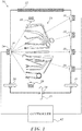
- FIG. 1 is a schematic diagram of a sterilization chamber 10 in accordance with an embodiment of the invention.
- the chamber 10 has a sealed portal 12 for passage of objects 14, which can be assorted surgical instruments and the like.
- Hydrogen peroxide is admitted into the chamber 10 via an inlet 16 having a regulator or valve 18.
- a portal 20 is provided for admission of air, and gas exits from the chamber through a portal 22.
- the chamber 10 is maintained at lower than atmospheric pressure, typically 0.5 torr, and features an ultraviolet light source 24 that transmits ultraviolet light through the chamber, which is received in multiple mural ultraviolet light detectors 26 and interior ultraviolet light detectors 28.
- Optics 30 having appropriate UV (ultraviolet) lenses that are associated with the ultraviolet source 24 are configured to illuminate all the detectors 26, 28.
- the distribution of the detectors 26, 28 in Fig. 1 is by way of example and not of limitation.
- the detectors 26, 28 may be distributed in the chamber such that the measurements optimally reflect the concentrations of hydrogen peroxide at the objects being sterilized.
- the detectors need not be distributed in any particular order, and may even be widely scattered about and within the chamber, facing in different directions.
- the ultraviolet source 24 receives command signals from a controller 42 and readouts from the detectors 26, 28.
- the valve 18 is adjusted by the controller 42 responsively to the readouts.
- the valve 18 regulates the inflow of hydrogen peroxide so as to achieve a desired optimum level (typically 95% concentration) of hydrogen peroxide within the chamber 10. Once the optimum level is achieved, in some embodiments the inflow may be discontinued and the chamber maintained in a static condition.
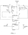
- Ultraviolet source 24 is realized as two light emitting diodes 32, 34 in parallel, both supplied by a controller 36.
- the diodes 32, 34 are in series with resistors 38, 40 and emit at 280 nm and 370 nm respectively.
- the diodes may emit simultaneously at respective frequencies, or at different time intervals at the same frequency.
- the Goertzel algorithm may be used in detecting the signals from the diodes 32, 34. Techniques of dual wavelength ultraviolet spectroscopy are known, for example, from U.S. Patent No. 6,269,680 , which is herein incorporated by reference.
- diode 34 acts as a reference to compensate for internal variations in the circuitry, while diode 32 emits at a wavelength that is strongly absorbed by hydrogen peroxide vapor.
- ultraviolet emitters known in the art could be used for the ultraviolet source 24, for example, cylindrical low pressure mercury UV emitters with a spectral peak at about 254 nm. Such emitters are proposed in U.S. Patent Application Publication No. 2006/0222576 , which is herein incorporated by reference.
- Other examples of such light sources include low pressure mercury vapor lamps, deuterium lamps, xenon lamps, light-emitting diodes and laser diodes. In general all of these are less convenient or more expensive than the dual light emitting diode configuration described above.
- the detectors 26, 28 are realized as a charge-coupled detector 44 across a resistor 46. Signals from the detector 44 are received in the controller 36 and conveyed to a remote site, such as a processor (not shown) by transceiver 48, where signal processing techniques are applied, including analog-to-digital conversion, and Fourier analysis, including the above-noted Goertzel algorithm.
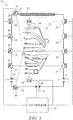
- FIG. 3 is a schematic diagram of a sterilization chamber 10 in accordance with an alternate embodiment of the invention in accordance with an embodiment of the invention.
- there are multiple ultraviolet sources 50 having optics 52 that direct the ultraviolet light toward respective detectors 26, 28.
- the optics of the detectors 26, 28 may include a convex lens.
- the light paths between the sources 50 and the detectors 26, 28 are indicated by broken lines.
Landscapes
- Health & Medical Sciences (AREA)
- Life Sciences & Earth Sciences (AREA)
- General Health & Medical Sciences (AREA)
- Animal Behavior & Ethology (AREA)
- Veterinary Medicine (AREA)
- Public Health (AREA)
- Epidemiology (AREA)
- Chemical & Material Sciences (AREA)
- General Chemical & Material Sciences (AREA)
- Chemical Kinetics & Catalysis (AREA)
- Physics & Mathematics (AREA)
- Spectroscopy & Molecular Physics (AREA)
- Analytical Chemistry (AREA)
- Pathology (AREA)
- Immunology (AREA)
- General Physics & Mathematics (AREA)
- Biochemistry (AREA)
- Apparatus For Disinfection Or Sterilisation (AREA)
- Investigating Or Analysing Materials By Optical Means (AREA)
- Physical Water Treatments (AREA)
Abstract
Description
- A portion of the disclosure of this patent document contains material that is subject to copyright protection. The copyright owner has no objection to the facsimile reproduction by anyone of the patent document or the patent disclosure, as it appears in the Patent and Trademark Office patent file or records, but otherwise reserves all copyright rights whatsoever.
- This invention relates to systems that analyze fluids by determining their chemical or physical properties. More particularly, this invention relates to determining the concentration of a gas in a sterilization chamber.
- One of the standard methods for low temperature sterilization of medical equipment is to use a combination of hydrogen peroxide (hydrogen peroxide) vapor with a low temperature plasma in a sterilization chamber. During the course of the sterilization process the hydrogen peroxide concentration is measured as it is consumed, and as necessary hydrogen peroxide is added to the chamber to maintain the concentration at a satisfactory level. A present method for measuring the hydrogen peroxide concentration uses an ultraviolet light source transmitting through the chamber, and the received ultraviolet light is measured with a single ultraviolet light detector that is located far from the source. The level of the received ultraviolet light is used to calculate a gross hydrogen peroxide concentration reading.
- One arrangement for measuring concentration of a sterilant is proposed in
U.S. Patent No. 7,880,887 to Olson et al. Measurements of the concentration of the sterilant in a sterilization chamber are provided through the use of a light source, a first detector that receives light from the light source that has not passed through the sterilization chamber and a detector that receives light from the light source that has passed through the sterilization chamber. The light contains wavelengths known to be absorbed by the sterilant. A controller receives and processes signals received from the two detectors to cancel changes in the output of the light source and then apply a modified Beer-Lambert law to determine the concentration of the sterilant gas. - In practice, concentration of a sterilant such as hydrogen peroxide may vary within the chamber, especially when sterilizing equipment with narrow lumens, such as catheters restricts diffusion of sterilant vapor. There may be areas of the chamber, which are exposed to higher or lower concentrations of hydrogen peroxide due to such flow restrictions. Thus the gross reading referred to above may not give an accurate picture of the concentration distribution over the chamber.
- The art has recognized that measurements in different areas of the sterilization chamber may improve the reliability of the readings of sterilant gas concentration. For example,
U.S. Patent No. 6,269,680 to Prieve et al. proposes includes a movable gas cell, which can be moved around the sterilization chamber so that measurements of the concentration of hydrogen peroxide can be done at various locations inside the sterilization chamber. The ends of the movable gas cell are connected to an ultraviolet lamp and a detector with optical fibers. - Embodiments of the invention use multiple ultraviolet (UV) detectors distributed over a sterilization chamber. The detectors may be relatively small (of the size of a coin), and may be configured to transmit their readings wirelessly to a central processor. In addition, rather than a single UV source, a double wavelength source is used to exploit differential absorption. To further improve the accuracy of the concentration readings, the source may be pulsed, which improves the signal-to-noise ratio.
- There is provided according to embodiments of the invention a sterilization chamber having an inlet for admitting a flow of sterilant fluid into the chamber, an ultraviolet light emitter arranged to direct ultraviolet light into the chamber, a plurality of ultraviolet light detectors disposed at respective locations for receiving the ultraviolet light, and a controller for regulating the flow of the sterilant fluid responsively to signals from the detectors to achieve a desired level of the sterilant fluid in the chamber.
- According to one aspect of the apparatus, the emitter emits light at a first wavelength that is absorbed by the sterilant fluid and at a second wavelength that is less well absorbed by the sterilant fluid.
- According to a further aspect of the apparatus, the sterilant fluid is hydrogen peroxide, the first wavelength is 280 nm and the second wavelength is 370 nm.
- According to yet another aspect of the apparatus, the emitter includes a plurality of emitters having optics arranged to direct light emissions to respective detectors.
- According to still another aspect of the apparatus, the chamber is maintained at lower than atmospheric pressure.
- According to an additional aspect of the apparatus, the emitter includes a plurality of light emitting diodes that are configured to emit at respective frequencies.
- According to another aspect of the apparatus, the emitter includes a plurality of light emitting diodes that are configured to emit at identical frequencies at different time intervals.
- There is further provided according to embodiments of the invention a method, which is carried out by admitting a flow of sterilant fluid into a sterilization chamber through an inlet, emitting ultraviolet light into the chamber, receiving the ultraviolet light in a plurality of ultraviolet light detectors disposed at respective locations, and regulating the flow of the sterilant fluid responsively to signals from the detectors to achieve a desired level of the sterilant fluid in the chamber.
- For a better understanding of the present invention, reference is made to the detailed description of the invention, by way of example, which is to be read in conjunction with the following drawings, wherein like elements are given like reference numerals, and wherein:
-
Fig. 1 is a schematic diagram of a sterilization chamber in accordance with an embodiment of the invention; -
Fig. 2 is an electrical schematic of components of the chamber shown inFig. 1 in accordance with an embodiment of the invention; and -
Fig. 3 is a schematic diagram of a sterilization chamber in accordance with an alternate embodiment of the invention. - In the following description, numerous specific details are set forth in order to provide a thorough understanding of the various principles of the present invention. It will be apparent to one skilled in the art, however, that not all these details are necessarily needed for practicing the present invention. In this instance, well-known circuits, control logic, and the details of computer program instructions for conventional algorithms and processes have not been shown in detail in order not to obscure the general concepts unnecessarily.
- Documents incorporated by reference herein are to be considered an integral part of the application except that, to the extent that any terms are defined in these incorporated documents in a manner that conflicts with definitions made explicitly or implicitly in the present specification, only the definitions in the present specification should be considered.
- Turning now to the drawings, Reference is made to
Fig. 1 , which is a schematic diagram of asterilization chamber 10 in accordance with an embodiment of the invention. Thechamber 10 has a sealedportal 12 for passage ofobjects 14, which can be assorted surgical instruments and the like. Hydrogen peroxide is admitted into thechamber 10 via aninlet 16 having a regulator orvalve 18. Aportal 20 is provided for admission of air, and gas exits from the chamber through aportal 22. Thechamber 10 is maintained at lower than atmospheric pressure, typically 0.5 torr, and features anultraviolet light source 24 that transmits ultraviolet light through the chamber, which is received in multiple muralultraviolet light detectors 26 and interiorultraviolet light detectors 28. Optics 30 having appropriate UV (ultraviolet) lenses that are associated with theultraviolet source 24 are configured to illuminate all thedetectors detectors Fig. 1 is by way of example and not of limitation. Thedetectors - The
ultraviolet source 24 receives command signals from acontroller 42 and readouts from thedetectors valve 18 is adjusted by thecontroller 42 responsively to the readouts. Thevalve 18 regulates the inflow of hydrogen peroxide so as to achieve a desired optimum level (typically 95% concentration) of hydrogen peroxide within thechamber 10. Once the optimum level is achieved, in some embodiments the inflow may be discontinued and the chamber maintained in a static condition. - Continued reference is made to
Fig. 1 and also toFig. 2 , which is an electrical schematic of components of thechamber 10 in accordance with an embodiment of the invention.Ultraviolet source 24 is realized as twolight emitting diodes controller 36. Thediodes resistors diodes U.S. Patent No. 6,269,680 , which is herein incorporated by reference. In the circuitry shown inFig. 2 diode 34 acts as a reference to compensate for internal variations in the circuitry, whilediode 32 emits at a wavelength that is strongly absorbed by hydrogen peroxide vapor. - A number of other ultraviolet emitters known in the art could be used for the
ultraviolet source 24, for example, cylindrical low pressure mercury UV emitters with a spectral peak at about 254 nm. Such emitters are proposed inU.S. Patent Application Publication No. 2006/0222576 , which is herein incorporated by reference. Other examples of such light sources include low pressure mercury vapor lamps, deuterium lamps, xenon lamps, light-emitting diodes and laser diodes. In general all of these are less convenient or more expensive than the dual light emitting diode configuration described above. - The
detectors detector 44 across aresistor 46. Signals from thedetector 44 are received in thecontroller 36 and conveyed to a remote site, such as a processor (not shown) bytransceiver 48, where signal processing techniques are applied, including analog-to-digital conversion, and Fourier analysis, including the above-noted Goertzel algorithm. - Reference is now made to
Fig. 3 , which is a schematic diagram of asterilization chamber 10 in accordance with an alternate embodiment of the invention in accordance with an embodiment of the invention. In this embodiment there are multipleultraviolet sources 50, havingoptics 52 that direct the ultraviolet light towardrespective detectors detectors sources 50 and thedetectors - It will be appreciated by persons skilled in the art that the present invention is not limited to what has been particularly shown and described hereinabove. Rather, the scope of the present invention includes both combinations and sub-combinations of the various features described hereinabove, as well as variations and modifications thereof that are not in the prior art, which would occur to persons skilled in the art upon reading the foregoing description.
Claims (15)
- An apparatus, comprising:a sterilization chamber having an inlet for admitting a flow of sterilant fluid into the chamber;an ultraviolet light emitter arranged to direct ultraviolet light into the chamber;a plurality of ultraviolet light detectors disposed at respective locations and receiving the ultraviolet light; anda controller for regulating the flow of the sterilant fluid responsively to signals from the detectors to achieve a desired level of the sterilant fluid in the chamber.
- The apparatus according to claim 1, wherein the emitter emits light at a first wavelength that is absorbed by the sterilant fluid and at a second wavelength that is less well absorbed by the sterilant fluid.
- The apparatus according to claim 2, wherein the sterilant fluid is hydrogen peroxide, the first wavelength is 280 nm and the second wavelength is 370 nm.
- The apparatus according to claim 1, wherein the emitter comprises a plurality of emitters having optics arranged to direct light emissions to respective detectors.
- The apparatus according to claim 1, wherein the chamber is maintained at lower than atmospheric pressure.
- The apparatus according to claim 1, wherein the emitter comprises a plurality of light emitting diodes that are configured to emit at respective frequencies.
- The apparatus according to claim 1, wherein the emitter comprises a plurality of light emitting diodes that are configured to emit at identical frequencies at different time intervals.
- A method, comprising the steps of:admitting a flow of sterilant fluid into a sterilization chamber through an inlet;emitting ultraviolet light into the chamber;receiving the ultraviolet light in a plurality of ultraviolet light detectors disposed at respective locations; andregulating the flow of the sterilant fluid responsively to signals from the detectors to achieve a desired level of the sterilant fluid in the chamber.
- The method according to claim 8, wherein emitting ultraviolet light comprises emitting the ultraviolet light at a first wavelength that is absorbed by the sterilant fluid and at a second wavelength that is less well absorbed by the sterilant fluid.
- The method according to claim 9, wherein the sterilant fluid is hydrogen peroxide, the first wavelength is 280 nm and the second wavelength is 370 nm.
- The method according to claim 8, wherein emitting ultraviolet light is performed with a plurality of emitters having optics arranged to direct light emissions to respective detectors.
- The method according to claim 8, further comprising maintaining the chamber at lower than atmospheric pressure.
- The method according to claim 8, wherein emitting ultraviolet light is performed by emitting the ultraviolet light using a plurality of light emitting diodes at respective frequencies.
- The method according to claim 8, wherein emitting ultraviolet light is performed by emitting the ultraviolet light using a plurality of light emitting diodes at identical frequencies at different time intervals.
- The method according to claim 8, wherein regulating comprises discontinuing the flow to maintain the chamber in a static condition.
Applications Claiming Priority (1)
| Application Number | Priority Date | Filing Date | Title |
|---|---|---|---|
| US15/399,671 US10610610B2 (en) | 2017-01-05 | 2017-01-05 | Hydrogen peroxide sterilizer with multiple UV sensors |
Publications (1)
| Publication Number | Publication Date |
|---|---|
| EP3345628A1 true EP3345628A1 (en) | 2018-07-11 |
Family
ID=60971995
Family Applications (1)
| Application Number | Title | Priority Date | Filing Date |
|---|---|---|---|
| EP18150366.5A Withdrawn EP3345628A1 (en) | 2017-01-05 | 2018-01-04 | Hydrogen peroxide sterilizer with multiple uv sensors |
Country Status (8)
| Country | Link |
|---|---|
| US (1) | US10610610B2 (en) |
| EP (1) | EP3345628A1 (en) |
| JP (1) | JP2018109630A (en) |
| CN (1) | CN108333133A (en) |
| AU (1) | AU2017279681A1 (en) |
| CA (1) | CA2990663A1 (en) |
| IL (1) | IL256422B (en) |
| RU (1) | RU2017145557A (en) |
Families Citing this family (1)
| Publication number | Priority date | Publication date | Assignee | Title |
|---|---|---|---|---|
| US20230060851A1 (en) * | 2021-09-01 | 2023-03-02 | Cardioquip, Llc | System and method for in-line optical sensing of hydrogen peroxide |
Citations (7)
| Publication number | Priority date | Publication date | Assignee | Title |
|---|---|---|---|---|
| US6269680B1 (en) | 1997-11-14 | 2001-08-07 | Ethicon, Inc. | Method and apparatus for measuring the concentration of hydrogen peroxide vapor |
| WO2003006963A1 (en) * | 2001-07-10 | 2003-01-23 | Steris Inc. | Monitor and control using mid-infrared spectroscopy for vapor hydrogen peroxide processing technics |
| US20060222576A1 (en) | 2003-08-13 | 2006-10-05 | Rudkowski Jan B | Device for the uv treatment of flowing fluids |
| EP2000156A2 (en) * | 2006-03-27 | 2008-12-10 | Sanyo Electric Co., Ltd. | Sterilization box |
| US7880887B2 (en) | 2008-08-29 | 2011-02-01 | Phygen, Inc. | Apparatus and method for measuring the concentration of gases in a sterilization chamber |
| WO2013143859A1 (en) * | 2012-03-27 | 2013-10-03 | Tetra Laval Holdings & Finance S.A. | A sensor arrangement for measuring the concentration of a substance |
| EP3056224A1 (en) * | 2009-09-30 | 2016-08-17 | TSO3 Inc. | Sterilization method |
Family Cites Families (14)
| Publication number | Priority date | Publication date | Assignee | Title |
|---|---|---|---|---|
| US4080076A (en) * | 1976-07-28 | 1978-03-21 | Optronix Inc. | Suspended solids analyzer using multiple light sources and photodetectors |
| US4172524A (en) * | 1977-05-04 | 1979-10-30 | The Upjohn Company | Inspection system |
| CA2217476C (en) * | 1995-04-06 | 2006-02-14 | Alfa Laval Agri Ab | Method and apparatus for quantitative particle determination in fluids |
| US5872359A (en) * | 1995-07-27 | 1999-02-16 | American Sterilizer Company | Real-time monitor and control system and method for hydrogen peroxide vapor decontamination |
| US6656424B1 (en) | 2000-02-18 | 2003-12-02 | Uvas, Llc | Ultraviolet area sterilizer and method of area sterilization using ultraviolet radiation |
| SE516643C2 (en) * | 2000-05-31 | 2002-02-05 | Tetra Laval Holdings & Finance | Process and apparatus for producing a gaseous medium |
| US6528016B1 (en) | 2000-06-27 | 2003-03-04 | Ethicon, Inc. | Method for rapidly determining the acceptability of loads to be sterilized |
| GB0816445D0 (en) * | 2008-09-09 | 2008-10-15 | Harley Phillip E | Instrument for determining ozone concentration |
| JP2010210565A (en) * | 2009-03-12 | 2010-09-24 | Noritsu Koki Co Ltd | Nitrogen dioxide concentration measuring apparatus and sterilizer |
| CA2681681A1 (en) * | 2009-10-06 | 2010-06-08 | Colin Irvin Wong | Mapping concentrations of airborne matter |
| BR112013026529A2 (en) | 2011-04-15 | 2016-09-20 | Samuel Richard Trapani | environment sterilization method and system |
| US9395246B2 (en) * | 2012-07-31 | 2016-07-19 | Alphasense Limited | Gas analyser |
| CN104755910B (en) * | 2012-09-04 | 2018-02-16 | Abb 技术有限公司 | Apparatus and method for monitoring the room equipped with high-tension apparatus |
| CN103453355B (en) * | 2013-04-09 | 2016-04-27 | 邓维增 | A kind of method and utensil realizing the compatible illumination of LED sterilization |
-
2017
- 2017-01-05 US US15/399,671 patent/US10610610B2/en not_active Expired - Fee Related
- 2017-12-19 IL IL256422A patent/IL256422B/en active IP Right Grant
- 2017-12-20 AU AU2017279681A patent/AU2017279681A1/en not_active Abandoned
- 2017-12-25 RU RU2017145557A patent/RU2017145557A/en not_active Application Discontinuation
-
2018
- 2018-01-03 CA CA2990663A patent/CA2990663A1/en not_active Abandoned
- 2018-01-04 EP EP18150366.5A patent/EP3345628A1/en not_active Withdrawn
- 2018-01-04 JP JP2018000093A patent/JP2018109630A/en active Pending
- 2018-01-05 CN CN201810010945.XA patent/CN108333133A/en active Pending
Patent Citations (8)
| Publication number | Priority date | Publication date | Assignee | Title |
|---|---|---|---|---|
| US6269680B1 (en) | 1997-11-14 | 2001-08-07 | Ethicon, Inc. | Method and apparatus for measuring the concentration of hydrogen peroxide vapor |
| WO2003006963A1 (en) * | 2001-07-10 | 2003-01-23 | Steris Inc. | Monitor and control using mid-infrared spectroscopy for vapor hydrogen peroxide processing technics |
| US20060222576A1 (en) | 2003-08-13 | 2006-10-05 | Rudkowski Jan B | Device for the uv treatment of flowing fluids |
| EP2000156A2 (en) * | 2006-03-27 | 2008-12-10 | Sanyo Electric Co., Ltd. | Sterilization box |
| US7880887B2 (en) | 2008-08-29 | 2011-02-01 | Phygen, Inc. | Apparatus and method for measuring the concentration of gases in a sterilization chamber |
| EP2337588B1 (en) * | 2008-08-29 | 2016-03-16 | Sterilucent, Inc. | Improved apparatus and method for measuring the conentration of gases in a sterilization chamber |
| EP3056224A1 (en) * | 2009-09-30 | 2016-08-17 | TSO3 Inc. | Sterilization method |
| WO2013143859A1 (en) * | 2012-03-27 | 2013-10-03 | Tetra Laval Holdings & Finance S.A. | A sensor arrangement for measuring the concentration of a substance |
Also Published As
| Publication number | Publication date |
|---|---|
| IL256422A (en) | 2018-01-31 |
| RU2017145557A (en) | 2019-06-25 |
| US20180185532A1 (en) | 2018-07-05 |
| JP2018109630A (en) | 2018-07-12 |
| CA2990663A1 (en) | 2018-07-05 |
| CN108333133A (en) | 2018-07-27 |
| IL256422B (en) | 2020-10-29 |
| AU2017279681A1 (en) | 2018-07-19 |
| US10610610B2 (en) | 2020-04-07 |
Similar Documents
| Publication | Publication Date | Title |
|---|---|---|
| US8085401B2 (en) | Ozone concentration sensor | |
| AU753047B2 (en) | Method for measuring the concentration of hydrogen peroxide vapor | |
| US7880887B2 (en) | Apparatus and method for measuring the concentration of gases in a sterilization chamber | |
| US10197545B2 (en) | Method and apparatus for measurement of a material in a liquid through absorption of light | |
| CN109827902A (en) | Water quality testing equipment and water quality testing method and device | |
| US10610610B2 (en) | Hydrogen peroxide sterilizer with multiple UV sensors | |
| TW202332897A (en) | Multi-wavelength ozone concentration sensor and method of use | |
| JP2010501833A (en) | System and method for compensating system delay in sample analysis | |
| US12209955B1 (en) | Device and method for gas concentration measurement | |
| KR20080067766A (en) | Optical measuring device of cell metabolism information | |
| US20200191713A1 (en) | Compact multi-wavelength tdlas system | |
| US10408755B2 (en) | Optical device and method for determining an optical property of specimen | |
| US8241563B2 (en) | Air sanitization system with fiber optic monitoring system | |
| US9970813B1 (en) | UV detection of sterilant concentration and dissipation in a volume of a chamber | |
| JP3245144U (en) | Gas concentration measuring device | |
| KR20230005519A (en) | Optic breath analysis apparatus | |
| JP7462859B1 (en) | Ozone concentration measuring device, ozone concentration measuring method, and ozone generation system | |
| CN118130406A (en) | A method, device and equipment for analyzing water quality | |
| JPH05132393A (en) | Chemical vapor deposition equipment | |
| CN118209505A (en) | Optical analysis device and composite analysis device | |
| Viallon et al. | Bureau International des Poids et Mesures |
Legal Events
| Date | Code | Title | Description |
|---|---|---|---|
| PUAI | Public reference made under article 153(3) epc to a published international application that has entered the european phase |
Free format text: ORIGINAL CODE: 0009012 |
|
| STAA | Information on the status of an ep patent application or granted ep patent |
Free format text: STATUS: THE APPLICATION HAS BEEN PUBLISHED |
|
| STAA | Information on the status of an ep patent application or granted ep patent |
Free format text: STATUS: REQUEST FOR EXAMINATION WAS MADE |
|
| AK | Designated contracting states |
Kind code of ref document: A1 Designated state(s): AL AT BE BG CH CY CZ DE DK EE ES FI FR GB GR HR HU IE IS IT LI LT LU LV MC MK MT NL NO PL PT RO RS SE SI SK SM TR |
|
| AX | Request for extension of the european patent |
Extension state: BA ME |
|
| 17P | Request for examination filed |
Effective date: 20180614 |
|
| RBV | Designated contracting states (corrected) |
Designated state(s): AL AT BE BG CH CY CZ DE DK EE ES FI FR GB GR HR HU IE IS IT LI LT LU LV MC MK MT NL NO PL PT RO RS SE SI SK SM TR |
|
| STAA | Information on the status of an ep patent application or granted ep patent |
Free format text: STATUS: EXAMINATION IS IN PROGRESS |
|
| 17Q | First examination report despatched |
Effective date: 20210527 |
|
| STAA | Information on the status of an ep patent application or granted ep patent |
Free format text: STATUS: THE APPLICATION HAS BEEN WITHDRAWN |
|
| 18W | Application withdrawn |
Effective date: 20210920 |