EP3345550A1 - Endoscope connector - Google Patents
Endoscope connector Download PDFInfo
- Publication number
- EP3345550A1 EP3345550A1 EP16841182.5A EP16841182A EP3345550A1 EP 3345550 A1 EP3345550 A1 EP 3345550A1 EP 16841182 A EP16841182 A EP 16841182A EP 3345550 A1 EP3345550 A1 EP 3345550A1
- Authority
- EP
- European Patent Office
- Prior art keywords
- endoscope
- connector
- ultrasound
- cable
- metal member
- Prior art date
- Legal status (The legal status is an assumption and is not a legal conclusion. Google has not performed a legal analysis and makes no representation as to the accuracy of the status listed.)
- Withdrawn
Links
Images






Classifications
-
- A—HUMAN NECESSITIES
- A61—MEDICAL OR VETERINARY SCIENCE; HYGIENE
- A61B—DIAGNOSIS; SURGERY; IDENTIFICATION
- A61B1/00—Instruments for performing medical examinations of the interior of cavities or tubes of the body by visual or photographical inspection, e.g. endoscopes; Illuminating arrangements therefor
- A61B1/00112—Connection or coupling means
- A61B1/00121—Connectors, fasteners and adapters, e.g. on the endoscope handle
- A61B1/00124—Connectors, fasteners and adapters, e.g. on the endoscope handle electrical, e.g. electrical plug-and-socket connection
-
- A—HUMAN NECESSITIES
- A61—MEDICAL OR VETERINARY SCIENCE; HYGIENE
- A61B—DIAGNOSIS; SURGERY; IDENTIFICATION
- A61B8/00—Diagnosis using ultrasonic, sonic or infrasonic waves
- A61B8/12—Diagnosis using ultrasonic, sonic or infrasonic waves in body cavities or body tracts, e.g. by using catheters
-
- A—HUMAN NECESSITIES
- A61—MEDICAL OR VETERINARY SCIENCE; HYGIENE
- A61B—DIAGNOSIS; SURGERY; IDENTIFICATION
- A61B8/00—Diagnosis using ultrasonic, sonic or infrasonic waves
- A61B8/44—Constructional features of the ultrasonic, sonic or infrasonic diagnostic device
- A61B8/4444—Constructional features of the ultrasonic, sonic or infrasonic diagnostic device related to the probe
-
- A—HUMAN NECESSITIES
- A61—MEDICAL OR VETERINARY SCIENCE; HYGIENE
- A61B—DIAGNOSIS; SURGERY; IDENTIFICATION
- A61B8/00—Diagnosis using ultrasonic, sonic or infrasonic waves
- A61B8/44—Constructional features of the ultrasonic, sonic or infrasonic diagnostic device
- A61B8/4444—Constructional features of the ultrasonic, sonic or infrasonic diagnostic device related to the probe
- A61B8/445—Details of catheter construction
-
- A—HUMAN NECESSITIES
- A61—MEDICAL OR VETERINARY SCIENCE; HYGIENE
- A61B—DIAGNOSIS; SURGERY; IDENTIFICATION
- A61B8/00—Diagnosis using ultrasonic, sonic or infrasonic waves
- A61B8/56—Details of data transmission or power supply
-
- A—HUMAN NECESSITIES
- A61—MEDICAL OR VETERINARY SCIENCE; HYGIENE
- A61B—DIAGNOSIS; SURGERY; IDENTIFICATION
- A61B1/00—Instruments for performing medical examinations of the interior of cavities or tubes of the body by visual or photographical inspection, e.g. endoscopes; Illuminating arrangements therefor
- A61B1/06—Instruments for performing medical examinations of the interior of cavities or tubes of the body by visual or photographical inspection, e.g. endoscopes; Illuminating arrangements therefor with illuminating arrangements
Definitions
- the present invention relates to an endoscope connector.
- the endoscope connector (connector portion) described in Patent Literature 1 includes an outer casing having an attachment hole, and an ultrasound connector attached to the attachment hole.
- a first metal member (connector portion main body) being a metal connected to a patient GND on the endoscope observation apparatus side
- the first and second metal members are electrically-isolated from each other, and electrically connected via a capacitor in a high-frequency manner, for causing an ultrasound image generated by the ultrasound observation apparatus, to be a good image with reduced noise, and assuring electrical safety.
- Patent Literature 1 JP 2007-185392 A
- the present invention has been contrived in view of the foregoing, and an object of the present invention is to provide an endoscope connector that can enhance assembling workability.
- an endoscope connector includes: an outer casing including an attachment hole configured to communicate between an inside and an outside of the outer casing; an electrical connector attached to the attachment hole; a first metal member disposed in the outer casing; a second metal member attached to the electrical connector; an insulating member placed between the first metal member and the second metal member in a state in which the electrical connector is attached to the attachment hole, the insulating member electrically insulating the first metal member and the second metal member from each other; a capacitor fixed to the insulating member; a first conduction member fixed to the insulating member and electrically connected to one leg of the capacitor, the first conduction member contacting the first metal member to be electrically connected to the first metal member in the state in which the electrical connector is attached to the attachment hole; and a second conduction member fixed to the insulating member and electrically connected to another leg of the capacitor, the second conduction member contacting the second metal member to be electrically connected to the second metal member in the
- the first conduction member is formed by a finger.
- the second conduction member is formed by a finger.
- the insulating member includes a coating portion configured to coat at least the one leg or the other leg of the capacitor.
- a thickness of the coating portion is 0.4 mm or more.
- the insulating member is formed in a container shape in which part of the electrical connector is accommodated, and the second conduction member contacts the second metal member fixed to the electrical connector and is electrically connected to the second metal member in a state in which the part of the electrical connector is accommodated in the insulating member.
- the first and second metal members are electrically insulated from each other by interposing the insulating member between the first and second metal members.
- the first and second metal members are electrically connected via the capacitor in a high-frequency manner.
- the endoscope connector according to the present invention brings about such an effect that the first and second metal members can be electrically connected via the capacitor in a high-frequency manner only by attaching the electrical connector to the attachment hole, and assembling workability can be enhanced.
- FIG. 1 is a diagram schematically illustrating an endoscope system 1 according to an embodiment of the present invention.
- the endoscope system 1 is a system for performing ultrasound diagnosis of the inside of a subject such as a human, using an ultrasound endoscope. As illustrated in FIG. 1 , the endoscope system 1 includes an endoscope 2, an ultrasound observation apparatus 3, an endoscope observation apparatus 4, and a display device 5.
- Part of the endoscope 2 can be inserted into a subject, and the endoscope 2 is an ultrasound endoscope having a function of transmitting an ultrasound pulse toward a body wall on the inside of the subject, receiving an ultrasound echo reflected by the subject, and outputting an echo signal, and a function of imaging the inside of the subject to output an image signal.
- the ultrasound observation apparatus 3 electrically-connects to the endoscope 2 via an ultrasound cable 31 ( FIG. 1 ), outputs a pulse signal to the endoscope 2 via the ultrasound cable 31, and inputs an echo signal from the endoscope 2. Then, the ultrasound observation apparatus 3 performs predetermined processing on the echo signal to generate an ultrasound image.
- An endoscope connector 6 (refer to FIG. 3 ) of the endoscope 2 that is to be described later is detachably connected to the endoscope observation apparatus 4.
- the endoscope observation apparatus 4 includes a video processor 41 and a light source device 42.
- the video processor 41 outputs a control signal to the endoscope 2 via the endoscope connector 6, and inputs an image signal from the endoscope 2 via the endoscope connector 6. Then, the video processor 41 performs predetermined processing on the image signal to generate an endoscope image.
- the light source device 42 supplies, via the endoscope connector 6, the endoscope 2 with illumination light for illuminating the inside of the subject.
- the display device 5 is formed by using a liquid crystal or an organic electro luminescence (EL), and displays the ultrasound image generated in the ultrasound observation apparatus 3, the endoscope image generated in the endoscope observation apparatus 4, and the like.
- EL organic electro luminescence
- the endoscope 2 includes an insertion portion 21, an operating unit 22, a universal cable 23, and the endoscope connector 6.
- a light guide for transmitting illumination light supplied from the light source device 42, a US cable for ultrasound observation (for the transmission of a pulse signal and an echo signal), an imaging cable C1 (refer to FIG. 2 ) for endoscope observation (for the transmission of a control signal, an image signal, and the like), and the like are laid in the endoscope 2 (in the insertion portion 21, the operating unit 22, the universal cable 23, and the endoscope connector 6), though these are not specifically illustrated in the drawing.
- the insertion portion 21 is a portion to be inserted into the subject. As illustrated in FIG. 1 , the insertion portion 21 includes an ultrasound probe 211 provided at a distal end, a rigid member 212 connected to a proximal end side (the operating unit 22 side) of the ultrasound probe 211, a curve portion 213 capable of curving that is connected to a proximal end side of the rigid member 212, and a flexible tube portion 214 having flexibility that is connected to a proximal end side of the curve portion 213.
- processing tool tubes into which various processing tools e.g., puncture needle, etc.
- processing tool tubes into which various processing tools are inserted, and the like are laid in the insertion portion 21 (the rigid member 212, the curve portion 213, and the flexible tube portion 214), though these are not specifically illustrated in the drawing.
- the ultrasound probe 211 is a convex-shaped ultrasound probe, and has a configuration in which a plurality of ultrasound transducers (not illustrated) are regularly-arrayed in such a manner as to form a convex-shaped arc.
- the ultrasound transducer includes an acoustic lens, a piezoelectric element, and a matching layer, and acquires an ultrasound echo contributing to an ultrasound tomographic image of the inside of the body wall on the inside of the subject.
- the ultrasound probe 211 converts a pulse signal input from the ultrasound observation apparatus 3 via the aforementioned US cable and the ultrasound cable 31, into an ultrasound pulse, and transmits the ultrasound pulse into the subject.
- the ultrasound probe 211 converts an ultrasound echo reflected inside the subject, into an electrical echo signal, and outputs the electrical echo signal to the ultrasound observation apparatus 3 via the above-described US cable and the ultrasound cable 31.
- the rigid member 212 is a hard member formed of resin material, and has a substantially-circular cylindrical shape.
- an observation window is formed in the rigid member 212, though these are not specifically illustrated in the drawing.
- the observation window, the illumination window, and the processing tool passage are holes penetrating through from the proximal end (end portion on the operating unit 22 side) of the rigid member 212 toward a distal end, and more specifically, have the following functions.
- the observation window is a hole for acquiring an optical image of the inside of the subject.
- an image sensor (not illustrated) that is connected to the aforementioned imaging cable C1 (refer to FIG. 2 ), and outputs an image signal according to the optical image of the inside of the subject, and an objective lens (not illustrated) are inserted into the observation window in a combined state.
- the image signal output from the image sensor is transmitted to the endoscope observation apparatus 4 (the video processor 41) via the aforementioned imaging cable C1 (refer to FIG. 2 ).
- the illumination window is a hole for emitting illumination light into the subject.
- an emission end side of the aforementioned light guide is inserted into the illumination window.
- the processing tool passage is a hole for causing the various processing tools to protrude outward.
- the aforementioned processing tool tube is connected to the processing tool passage.
- the operating unit 22 is a portion that is connected to a proximal end side of the insertion portion 21, and receives various operations from a doctor or the like. As illustrated in FIG. 1 , the operating unit 22 includes a curve knob 221 for performing a curving operation of the curve portion 213, and a plurality of operating members 222 for performing various operations.
- a processing tool insertion port 223 that is communicated with the aforementioned processing tool tube, and is provided for inserting the various processing tools into the processing tool tube is formed in the operating unit 22.
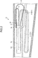
- FIG. 2 is a diagram illustrating a wiring state of the imaging cable C1 in the operating unit 22.
- the imaging cable C1 ( FIG. 2 ) is wired in the following manner.
- the imaging cable C1 includes a first imaging cable C11 and a second imaging cable C12.
- One end of the first imaging cable C11 is electrically connected to the aforementioned image sensor, and the other end thereof is electrically connected to a relay board Rb provided in the operating unit 22 while repeating meandering a plurality of times.
- the first imaging cable C11 performs transmission of an image signal and a control signal between the aforementioned image sensor and the relay board Rb.
- the relay board Rb is illustrated using a dashed-dotted line in FIG. 2 , and the relay board Rb has a box shape, and is provided in a shield member Sh1 connected to the same electric potential as a patient GND on the endoscope observation apparatus 4 side.
- One end of the second imaging cable C12 is electrically connected to the relay board Rb, and the other end thereof is electrically connected to a first circuit board Cb1 (refer to FIG. 5 ) to be described later that is provided in the endoscope connector 6.
- the second imaging cable C12 performs transmission of an image signal and a control signal between the relay board Rb and the first circuit board Cb1.
- respective one ends of jumper lines J1 and J2 are electrically connected to respective shields (e.g., braided shield, etc.) of the aforementioned first and second imaging cables C11 and C12. Then, the respective other ends of the jumper lines J1 and J2 are fastened together by a screw Sc onto the shield member Sh1 via lug terminals R1 and R2.
- shields e.g., braided shield, etc.
- the respective shields of the first and second imaging cables C11 and C12 are ensured at the same electric potential, and connected to the same electric potential as the patient GND.
- the universal cable 23 is a cable having one end connected to the operating unit 22, and is a cable in which a remote switch cable for transmitting an operation signal according to various operations performed on the operating unit 22 (e.g., operations for instructing freeze, release, and edge enhancement of an endoscope image, an operation for instructing light adjustment of the light source device 42, etc.) is laid in addition to the aforementioned light guide, the US cable, and the imaging cable (the second imaging cable C12).
- operations performed on the operating unit 22 e.g., operations for instructing freeze, release, and edge enhancement of an endoscope image, an operation for instructing light adjustment of the light source device 42, etc.
- the endoscope connector 6 is provided at the other end of the universal cable 23, and is a connector for connecting to the ultrasound cable 31 connected to the ultrasound observation apparatus 3, and the endoscope observation apparatus 4 (the video processor 41 and the light source device 42).
- an upper side in the posture is regarded as "up”
- a downside in the posture is regarded as “down”
- a side approaching the endoscope observation apparatus 4 is regarded as "front”
- a side separated from the endoscope observation apparatus 4 is regarded as "rear”
- a left side viewed from a front side in the posture is regarded as "left”
- a right side viewed from the front side in the posture is regarded as "right”.
- FIG. 3 is perspective view of the endoscope connector 6 viewed from the front side and an upper left side.
- FIG. 4 is a perspective view illustrating a state in which an ultrasound connector 63 is removed from the endoscope connector 6 illustrated in FIG. 3 .
- FIGS. 3 and 4 for identifying the aforementioned "up and down”, “front and rear”, and “left and right” of the endoscope connector 6, an XYZ orthogonal coordinate is illustrated.
- a +Z-axis direction is the “upper direction” of the endoscope connector 6.
- a +X-axis direction is the “left direction” of the endoscope connector 6.
- a +Y-axis direction is the "front direction” of the endoscope connector 6.
- the endoscope connector 6 includes an outer casing 61, a plug portion 62, the ultrasound connector 63 ( FIG. 3 ), a first metal member 64 ( FIG. 4 ), a second metal member 65 (refer to FIG. 8 ), and an insulating member 66 (refer to FIGS. 9 to 11 ).
- the outer casing 61 has a substantially-cylindrical shape extending in the front and rear direction (Y-axis direction).
- the universal cable 23 (the aforementioned light guide, the US cable, the imaging cable (the second imaging cable C12), the remote switch cable, etc.) is inserted into the outer casing 61.
- a bend protection member 611 is provided on the rear side of the outer casing 61.
- a protruding portion 612 protruding in the X-axis direction is formed on the side surface of the above-described outer casing 61.
- the protruding portion 612 is communicated with the inside of the outer casing 61, and has a hollow shape.
- an attachment hole 612A having an aperture surface positioned on a YZ plane, and communicating the inside and the outside of the outer casing 61 is formed in the protruding portion 612.
- the attachment hole 612A is a hole to which the ultrasound connector 63 is attached.
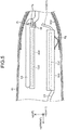
- FIGS. 5 and 6 are diagrams illustrating a wiring state of a US cable C2 in the outer casing 61. More specifically, FIG. 5 is a diagram illustrating the wiring state viewed from the right side illustrated in FIG. 3 or 4 . FIG. 6 is a diagram illustrating the wiring state viewed from the upper side illustrated in FIG. 3 or 4 .
- the first circuit board Cb1 ( FIG. 5 ), a second circuit board Cb2 ( FIG. 5 ), a shield casing Sh2 ( FIG. 5 ), and the like are provided in the outer casing 61.
- the first and second circuit boards Cb1 and Cb2 are supported by the first metal member 64 in the outer casing 61, in a posture substantially-parallel to an XY plane, and in a posture in which they face each other in the Z-axis direction.
- first metal member 64 for the convenience of explanation, only part of the first metal member 64 is illustrated, and the other parts are not illustrated in the drawings.
- the first circuit board Cb1 is electrically connected to first and second electrical contact points 621A and 622A of the plug portion 62 via a signal cable C3, and the other end of the second imaging cable C12 is connected thereto.
- the first circuit board Cb1 is illustrated using a dashed-dotted line in FIG. 5 , and the first circuit board Cb1 has a box shape, and is provided in a shield member Sh3 connected to the same electric potential as the patient GND on the endoscope observation apparatus 4 side.
- the second circuit board Cb2 is provided in the outer casing 61 in a posture parallel to the first circuit board Cb1.
- the second circuit board Cb2 is electrically connected to the first circuit board Cb1 so that signal transmission can be performed with the first circuit board Cb1 via a signal cable, and the aforementioned remote switch cable laid from the operating unit 22 to the inside of the outer casing 61 via the universal cable 23 is connected to the second circuit board Cb2, though these are not specifically illustrated in the drawing.
- the remote switch cable is connected to a flexible board Fp ( FIG. 5 , FIG. 6 ).
- the flexible board Fp is connected to a flexible printed circuits (FPC) connector (not illustrated) mounted on the second circuit board Cb2, from the rear side of the second circuit board Cb2.
- FPC flexible printed circuits
- the second circuit board Cb2 is illustrated using a dashed-dotted line in FIGS. 5 and 6 , and the second circuit board Cb2 has a box shape, and is provided in a shield member Sh4 connected to the same electric potential as the patient GND on the endoscope observation apparatus 4 side.
- the US cable C2 is provided in the outer casing 61 at a position distant from the first circuit board Cb1, that is, provided on a top surface of the second circuit board Cb2, and is laid toward the ultrasound connector 63 side while repeating meandering a plurality of times.
- the US cable C2 is laid at a position separated from a location where noise is easily generated from the first circuit board Cb1 electrically connected at a position closest to the endoscope observation apparatus 4 when the first and second circuit boards Cb1 and Cb2 are compared, that is, at a position separated from the first circuit board Cb1.
- the influence of noise exerted on the US cable C2 can be suppressed, and an ultrasound image can be a good image with a reduced noise.
- the aforementioned meandering portion that is, a portion bent at an angle equal to or smaller than at least 90° is coated with a heat shrinkable tube in a not-shrunk state, for preventing damages to the portion.
- the portion may be similarly coated with a heat shrinkable tube in a not-shrunk state.
- a fixing pin Pi is attached in a portion positioned on the rear side of the second circuit board Cb2.
- the fixing pin Pi is positioned between the flexible board Fp and the US cable C2.
- the fixing pin Pi can prevent mechanical interference between the flexible board Fp and the US cable C2, and prevent the flexible board Fp from being removed from the FPC connector mounted on the second circuit board Cb2.
- the shield casing Sh2 is a shield member having a substantially-cylindrical shape following the inner surface of the outer casing 61.
- the shield casing Sh2 is electrically connected to the shield member Sh3 via a finger Fg.
- the shield casing Sh2 is connected to the same electric potential as the patient GND on the endoscope observation apparatus 4 side, and reduces radiation noise generated from the first and second circuit boards Cb1 and Cb2.
- the plug portion 62 is a portion to be inserted into the endoscope observation apparatus 4, and connected to the video processor 41 and the light source device 42, and is attached to an aperture portion on the front side of the outer casing 61 as illustrated in FIG. 3 or 4 .
- the plug portion 62 includes first and second electrical connector portions 621 and 622, and a light guide cap 623.
- the first electrical connector portion 621 is positioned on the rearmost side of the plug portion 62, and has a circular cylindrical shape extending in the front and rear direction.
- first electrical contact points 621A is provided in a circumferential direction.
- the second electrical connector portion 622 is integrally formed on the front side of the first electrical connector portion 621, and has a circular cylindrical shape having an outer dimension smaller than an outer dimension of the first electrical connector portion 621.
- a plurality of second electrical connector portions 622A is provided in the circumferential direction.
- the above-described plurality of first and second electrical contact points 621A and 622A are electrically connected to the imaging cable C1 and the aforementioned remote switch cable via the signal cable C3 and the first and second circuit boards Cb1 and Cb2.
- the plurality of first and second electrical contact points 621A and 622A are electrically connected to the video processor 41 in a state in which the plug portion 62 is inserted into the endoscope observation apparatus 4.
- the plurality of first and second electrical contact points 621A and 622A are portions electrically-connecting the imaging cable C1 and the aforementioned remote switch cable, and the video processor 41.
- the light guide cap 623 is attached to an end surface on the front side of the second electrical connector portion 622, and protrudes from the end surface on the front side in the +Y-axis direction.
- an incidence end side of the aforementioned light guide is inserted into the light guide cap 623.
- the light guide cap 623 connects to the light source device 42 in a state in which the plug portion 62 is inserted into the endoscope observation apparatus 4.
- the light guide cap 623 is a portion optically-connecting the aforementioned light guide and the light source device 42.
- FIG. 7 is a perspective view of the ultrasound connector 63 removed from the endoscope connector 6, viewed from an outer casing 61 inner side.
- the ultrasound connector 63 is an electrical connector for electrically-connecting the US cable C2 and the ultrasound cable 31. As illustrated in FIG. 3 or 7 , the ultrasound connector 63 includes an ultrasound board 631 ( FIG. 7 ), a frame member 632, an electrical connection member 633 ( FIG. 7 ), and a spacer 634 ( FIG. 7 ).
- the ultrasound board 631 has a substantially-circular disc shape, and is a board having a surface (surface on the outer casing 61 inner side) on which a plurality of (12 in the present embodiment) FPC connectors 6311 ( FIG. 7 ) and a plurality of pin terminals 6312 ( FIG. 3 , FIG. 7 ) are mounted.
- one end of the US cable C2 laid toward the ultrasound connector 63 side is connected to a plurality of flexible boards (not illustrated).
- the plurality of flexible boards (the US cable C2) is connected to the plurality of FPC connectors 6311.
- the plurality of pin terminals 6312 are arrayed in a matrix in a substantially-center portion of the ultrasound board 631.
- the plurality of pin terminals 6312 are electrically connected to the US cable C2 via the FPC connectors 6311 and the aforementioned plurality of flexible boards, and electrically connected to the ultrasound cable 31 when the ultrasound cable 31 is connected to the ultrasound connector 63.
- the frame member 632 is formed by a cylindrical metal member, and is a portion mechanically-connected to a connector on the ultrasound cable 31 side.
- the frame member 632 supports the ultrasound board 631 in an aperture portion on one end side (the outer casing 61 inner side).
- the electrical connection member 633 is formed by a metal member having an L-shaped cross-section, and in a posture in which a portion 6331 on one end side of the L-shaped cross-section faces the surface of the ultrasound board 631 (surface on the outer casing 61 inner side), a portion 6332 on the other end side of the L-shaped cross-section is connected to the frame member 632.
- an insulating sheet 6333 is provided between the portion 6331 on one end side of the L-shaped cross-section in the electrical connection member 633, and the surface of the ultrasound board 631 (the plurality of pin terminals 6312).
- one end side of the US cable C2 is fixed to the portion 6331 on one end side of the L-shaped cross-section in the electrical connection member 633.
- the spacer 634 is a metal member (shield member) having a substantially-cylindrical shape partially covering an outer rim portion of the ultrasound board 631, and is fixed to one end side of the frame member 632 (the outer casing 61 inner side).
- the first metal member 64 is a metal frame for reinforcement that extends in the front and rear direction (Y-axis direction) in the outer casing 61, and supports the first and second circuit boards Cb1 and Cb2 and the like as mentioned above.
- the first metal member 64 is connected to the same electric potential as the patient GND on the endoscope observation apparatus 4 side.
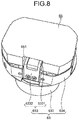
- FIG. 8 is a perspective view illustrating a state in which the second metal member 65 is attached to the ultrasound connector 63 illustrated in FIG. 7 .
- the second metal member 65 is formed in a container shape, and is fixed by a screw or the like to the frame member 632 so as to cover part of an outer rim portion of the ultrasound board 631 (outer rim portion not covered by the spacer 634), and the surface of the ultrasound board 631.
- the ultrasound board 631 is shielded almost completely by its periphery being covered by the frame member 632, the electrical connection member 633, the spacer 634, and the second metal member 65, and has a structure strong to exogenous noise.
- the aforementioned frame member 632, the electrical connection member 633, the spacer 634, and the second metal member 65 are connected to the same electric potential as a grounding GND on the ultrasound observation apparatus 3 side via the ultrasound cable 31.
- a cutout portion 651 for inserting one end side of the US cable C2 into the second metal member 65 is formed in a side surface portion facing the electrical connection member 633 when the second metal member 65 is fixed to the frame member 632.
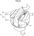
- FIG. 9 is a perspective view illustrating a state in which the insulating member 66 is attached to the ultrasound connector 63 illustrated in FIG. 8 .
- the insulating member 66 is a member formed of insulating material, and electrically-insulating the first and second metal members 64 and 65 from each other.
- the insulating member 66 includes an insulating member main body 661 and a protection member 662.
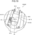
- FIG. 10 is a perspective view of the insulating member main body 661 viewed from the outer casing 61 inner side.
- FIG. 11 is a perspective view of the insulating member main body 661 viewed from the ultrasound connector 63 side.
- the insulating member main body 661 has a bottomed cylindrical shape, and is fixed by a screw or the like to the frame member 632 via the spacer 634 or the second metal member 65 in a state in which part of the ultrasound connector 63 is accommodated thereinside. In a state in which part of the ultrasound connector 63 is accommodated in the insulating member main body 661, the insulating member main body 661 covers the entire second metal member 65.
- the insulating member main body 661 is interposed (sandwiched) between the first and second metal members 64 and 65, to electrically insulate the first and second metal members 64 and 65 from each other.
- a storage portion 6611 ( FIG. 10 ), a first recess portion 6612 ( FIG. 10 ), a second recess portion 6613( FIG. 11 ), and a cutout portion 6614 are formed in a bottom portion.
- the storage portion 6611 is formed on a lateral surface (surface on the outer casing 61 inner side) of the bottom portion of the insulating member main body 661. As illustrated in FIG. 10 , the storage portion 6611 includes first and second wall portions 6611A and 6611B protruding from the lateral surface and extending parallel to each other, a third wall portion 6611C protruding from the lateral surface and connecting between the first and second wall portions 6611A and 6611B, and a block portion 6611D extending parallel to the lateral surface, and installed across the first to third wall portions 6611A to 6611C. In other words, the storage portion 6611 includes an aperture portion 6611E on a side separated from the third wall portion 6611C, and is configured to be able to store a predetermined member through the aperture portion 6611E.
- a capacitor 67 is provided in the storage portion 6611 through the aperture portion 6611E.
- first and second wall portions 6611A and 6611B are formed to extend in the same direction as the portion 6331 on one end side of the L-shaped cross-section in the electrical connection member 633, in a state in which the insulating member main body 661 is fixed to the frame member 632.
- the first recess portion 6612 is a recess portion formed on the lateral surface of the bottom portion of the insulating member main body 661, and is formed at a position adjacent to the aperture portion 6611E.
- a first finger 68 functioning as a first conduction member according to the present invention is fixed to the first recess portion 6612.
- one leg 671 of the capacitor 67 provided in the storage portion 6611 is pulled out to the outside of the storage portion 6611 through the aperture portion 6611E, and fixed by soldering or the like to the first finger 68 fixed to the first recess portion 6612.
- the second recess portion 6613 is a recess portion formed on a medial surface (surface of the ultrasound connector 63 side) of the bottom portion of the insulating member main body 661, and is formed at a position proximate to the third wall portion 6611C.
- a communication hole 6613A communicated with the inside of the storage portion 6611 is formed in the second recess portion 6613.
- a second finger 69 functioning as a second conduction member according to the present invention is fixed to the second recess portion 6613.
- the other leg 672 of the capacitor 67 provided in the storage portion 6611 is pulled out to the inside of the second recess portion 6613 through the communication hole 6613A, and fixed by soldering or the like to the second finger 69 fixed to the second recess portion 6613.
- the second finger 69 contacts the second metal member 65 to be electrically connected to the second metal member 65.
- the first finger 68 contacts the first metal member 64 to be electrically connected to the first metal member 64.
- the first and second metal members 64 and 65 are electrically connected via the capacitor 67 in a high-frequency manner.
- the above-described insulating member main body 661 covers one leg 671 of the capacitor 67 and the first finger 68 when viewed from the ultrasound connector 63 side ( FIG. 11 ).
- the insulating member main body 661 covers the other leg 672 of the capacitor 67 and the second finger 69 when viewed from the outer casing 61 inner side ( FIG. 10 ).
- the insulating member main body 661 has a function as a coating portion according to the present invention.
- insulating member main body 661 is formed so as to have a thickness of 0.4 mm or more.
- the cutout portion 6614 is a portion in which part of the side surface portion of the insulating member main body 661 is cut out, and is formed at a position facing the cutout portion 651 of the second metal member 65 in a state in which the insulating member main body 661 is fixed to the frame member 632.
- one end side of the US cable C2 is inserted into the insulating member main body 661 (the second metal member 65) through the cutout portion 6614 (651), and is fixed to the portion 6331 on one end side of the L-shaped cross-section in the electrical connection member 633.
- the protection member 662 is a member for protecting one end side of the US cable C2 that is inserted into the insulating member main body 661 and the second metal member 65 through the cutout portions 6614 and 651.
- the protection member 662 has an L-shaped cross-section, and is fixed by a screw or the like to the frame member 632 in a state in which the US cable C2 fixed to the electrical connection member 633 is bent upward in FIG. 9 (the outer casing 61 inner side) in a portion 6621 on one end side of the L-shaped cross-section, and is further bent in a portion 6622 on the other end side of the L-shaped cross-section so as to follow the outer surface of the block portion 6611D.
- one end side of the US cable C2 fixed to the electrical connection member 633 is brought into a state of being fixed in a posture having a substantially-U-shape (illustrated using a broken line in FIG. 9 ), by the protection member 662, and the US cable C2 can be protected in a state in which a bending R regulation of a substantially-U-shaped portion, and the regulated bending R are maintained.
- the first and second metal members 64 and 65 are electrically insulated from each other by interposing the insulating member 66 between the first and second metal members 64 and 65.
- the first and second metal members 64 and 65 are electrically connected via the capacitor 67 in a high-frequency manner.
- the endoscope connector 6 brings about such an effect that the first and second metal members 64 and 65 can be electrically connected via the capacitor 67 in a high-frequency manner only by attaching the ultrasound connector 63 to the attachment hole 612A, and assembling workability can be enhanced.
- the first and second fingers 68 and 69 are employed as the first and second conduction members according to the present invention.
- the legs 671 and 672 of the capacitor 67 and the first and second metal members 64 and 65 can be electrically connected with certainty using a simple configuration.
- the insulating member main body 661 functioning as the coating portion according to the present invention is set to have the entire thickness of 0.4 mm or more.
- the first and second metal members 64 and 65 can be electrically insulated from each other with certainty.
- the insulating member main body 661 is formed in a container shape in which part of the ultrasound connector 63 is accommodated.
- the other leg 672 (second finger 69) of the capacitor 67 and the second metal member 65 can be electrically connected.
- assembling workability of the endoscope connector 6 can be further enhanced.
- the endoscope system 1 has both of a function for generating an ultrasound image, and a function for generating an endoscope image. Nevertheless, the endoscope system 1 is not limited to this configuration, and the endoscope system 1 may have a configuration only haying either one of the functions.
- the insulating member main body 661 is formed in a container shape. Nevertheless, the insulating member main body 661 is not limited to this configuration, and may have a configuration only including a bottom portion by omitting a side surface portion of the insulating member main body 661, for example, as long as the first and second metal members 64 and 65 can be electrically insulated from each other.
- the storage portion 6611 is formed on the lateral surface of the bottom portion of the insulating member main body 661. Nevertheless, the storage portion 6611 is not limited to this configuration, and may have a configuration formed on the medial surface of the bottom portion of the insulating member main body 661.
- capacitor 67 only one capacitor 67 is provided. Nevertheless, the number of capacitors 67 is not limited to this. As another configuration, two or more capacitors 67 may be provided as long as the capacitors 67 are connected in parallel.
- the endoscope system 1 is not limited to the medical field, and may be used in the industrial field, and used as an endoscope system that observes the inside of a subject such as a machine structure.
Landscapes
- Health & Medical Sciences (AREA)
- Life Sciences & Earth Sciences (AREA)
- Surgery (AREA)
- Engineering & Computer Science (AREA)
- Medical Informatics (AREA)
- Animal Behavior & Ethology (AREA)
- Radiology & Medical Imaging (AREA)
- Nuclear Medicine, Radiotherapy & Molecular Imaging (AREA)
- Biomedical Technology (AREA)
- Heart & Thoracic Surgery (AREA)
- Physics & Mathematics (AREA)
- Molecular Biology (AREA)
- Biophysics (AREA)
- Pathology (AREA)
- General Health & Medical Sciences (AREA)
- Public Health (AREA)
- Veterinary Medicine (AREA)
- Optics & Photonics (AREA)
- Computer Networks & Wireless Communication (AREA)
- Endoscopes (AREA)
- Ultra Sonic Daignosis Equipment (AREA)
Abstract
Description
- The present invention relates to an endoscope connector.
- There has been conventionally known an endoscope system in which an ultrasound endoscope including an insertion portion to be inserted into a subject, an ultrasound observation apparatus that processes a signal from an ultrasound transducer provided at a distal end of the insertion portion, and an endoscope observation apparatus that processes a signal from an image sensor provided at the distal end of the insertion portion are connected via an endoscope connector (for example, refer to Patent Literature 1).
- The endoscope connector (connector portion) described in
Patent Literature 1 includes an outer casing having an attachment hole, and an ultrasound connector attached to the attachment hole. In addition, a first metal member (connector portion main body) being a metal connected to a patient GND on the endoscope observation apparatus side, and a second metal member (metal member) being a grounding GND metal on the ultrasound observation apparatus side that is attached to the ultrasound connector are provided in the outer casing. In addition, the first and second metal members are electrically-isolated from each other, and electrically connected via a capacitor in a high-frequency manner, for causing an ultrasound image generated by the ultrasound observation apparatus, to be a good image with reduced noise, and assuring electrical safety. - Patent Literature 1:
JP 2007-185392 A - Nevertheless, in the endoscope connector described in
Patent Literature 1, when the first and second metal members are electrically connected via the capacitor in a high-frequency manner, the capacitor and the first metal member, and the capacitor and the second metal member are connected by respective lead wires. Thus, in assembling the endoscope connector, it is necessary to perform a connecting work for the lead wires. This causes such a problem that it is difficult to enhance assembling workability. - The present invention has been contrived in view of the foregoing, and an object of the present invention is to provide an endoscope connector that can enhance assembling workability.
- To solve the above-described problem and achieve the object, an endoscope connector according to the present invention includes: an outer casing including an attachment hole configured to communicate between an inside and an outside of the outer casing; an electrical connector attached to the attachment hole; a first metal member disposed in the outer casing; a second metal member attached to the electrical connector; an insulating member placed between the first metal member and the second metal member in a state in which the electrical connector is attached to the attachment hole, the insulating member electrically insulating the first metal member and the second metal member from each other; a capacitor fixed to the insulating member; a first conduction member fixed to the insulating member and electrically connected to one leg of the capacitor, the first conduction member contacting the first metal member to be electrically connected to the first metal member in the state in which the electrical connector is attached to the attachment hole; and a second conduction member fixed to the insulating member and electrically connected to another leg of the capacitor, the second conduction member contacting the second metal member to be electrically connected to the second metal member in the state in which the electrical connector is attached to the attachment hole.
- Moreover, in the above-described endoscope connector according to the present invention, the first conduction member is formed by a finger.
- Moreover, in the above-described endoscope connector according to the present invention, the second conduction member is formed by a finger.
- Moreover, in the above-described endoscope connector according to the present invention, the insulating member includes a coating portion configured to coat at least the one leg or the other leg of the capacitor.
- Moreover, in the above-described endoscope connector according to the present invention, a thickness of the coating portion is 0.4 mm or more.
- Moreover, in the above-described endoscope connector according to the present invention, the insulating member is formed in a container shape in which part of the electrical connector is accommodated, and the second conduction member contacts the second metal member fixed to the electrical connector and is electrically connected to the second metal member in a state in which the part of the electrical connector is accommodated in the insulating member.
- In the endoscope connector according to the present invention, the first and second metal members are electrically insulated from each other by interposing the insulating member between the first and second metal members. In addition, by fixing the capacitor and the first and second conduction members to the insulating member, when the electrical connector is attached to the attachment hole, the first and second metal members are electrically connected via the capacitor in a high-frequency manner.
- Thus, the endoscope connector according to the present invention brings about such an effect that the first and second metal members can be electrically connected via the capacitor in a high-frequency manner only by attaching the electrical connector to the attachment hole, and assembling workability can be enhanced.
-
-
FIG. 1 is a diagram schematically illustrating an endoscope system according to an embodiment of the present invention. -
FIG. 2 is a diagram illustrating a wiring state of an imaging cable in an operating unit illustrated inFIG. 1 . -
FIG. 3 is perspective view of an endoscope connector illustrated inFIG. 1 , viewed from a front side and an upper left side. -
FIG. 4 is a perspective view illustrating a state in which an ultrasound connector is removed from the endoscope connector illustrated inFIG. 3 . -
FIG. 5 is a diagram illustrating a wiring state of a US cable in an outer casing illustrated inFIGS. 3 and4 . -
FIG. 6 is a diagram illustrating a wiring state of a US cable in the outer casing illustrated inFIGS. 3 and4 . -
FIG. 7 is a perspective view of the ultrasound connector removed from the endoscope connector illustrated inFIG. 3 , viewed from an outer casing inner side. -
FIG. 8 is a perspective view illustrating a state in which a second metal member is attached to the ultrasound connector illustrated inFIG. 7 . -
FIG. 9 is a perspective view illustrating a state in which an insulating member is attached to the ultrasound connector illustrated inFIG. 8 . -
FIG. 10 is a perspective view of an insulating member main body illustrated inFIG. 9 , viewed from an outer casing inner side. -
FIG. 11 is a perspective view of the insulating member main body illustrated inFIG. 9 , viewed from an ultrasound connector side. - A mode for carrying out the present invention (hereinafter, referred to as an embodiment) will be described below with reference to the drawings. In addition, the present invention is not limited by the embodiment to be described below. Furthermore, in the description of the drawings, the same parts are assigned the same signs.
-
FIG. 1 is a diagram schematically illustrating anendoscope system 1 according to an embodiment of the present invention. - The
endoscope system 1 is a system for performing ultrasound diagnosis of the inside of a subject such as a human, using an ultrasound endoscope. As illustrated inFIG. 1 , theendoscope system 1 includes anendoscope 2, anultrasound observation apparatus 3, anendoscope observation apparatus 4, and adisplay device 5. - Part of the
endoscope 2 can be inserted into a subject, and theendoscope 2 is an ultrasound endoscope having a function of transmitting an ultrasound pulse toward a body wall on the inside of the subject, receiving an ultrasound echo reflected by the subject, and outputting an echo signal, and a function of imaging the inside of the subject to output an image signal. - In addition, a detailed configuration of the
endoscope 2 will be described later. - The
ultrasound observation apparatus 3 electrically-connects to theendoscope 2 via an ultrasound cable 31 (FIG. 1 ), outputs a pulse signal to theendoscope 2 via theultrasound cable 31, and inputs an echo signal from theendoscope 2. Then, theultrasound observation apparatus 3 performs predetermined processing on the echo signal to generate an ultrasound image. - An endoscope connector 6 (refer to
FIG. 3 ) of theendoscope 2 that is to be described later is detachably connected to theendoscope observation apparatus 4. As illustrated inFIG. 1 , theendoscope observation apparatus 4 includes avideo processor 41 and alight source device 42. - The
video processor 41 outputs a control signal to theendoscope 2 via theendoscope connector 6, and inputs an image signal from theendoscope 2 via theendoscope connector 6. Then, thevideo processor 41 performs predetermined processing on the image signal to generate an endoscope image. - The
light source device 42 supplies, via theendoscope connector 6, theendoscope 2 with illumination light for illuminating the inside of the subject. - The
display device 5 is formed by using a liquid crystal or an organic electro luminescence (EL), and displays the ultrasound image generated in theultrasound observation apparatus 3, the endoscope image generated in theendoscope observation apparatus 4, and the like. - As illustrated in
FIG. 1 , theendoscope 2 includes aninsertion portion 21, anoperating unit 22, auniversal cable 23, and theendoscope connector 6. - Here, a light guide for transmitting illumination light supplied from the
light source device 42, a US cable for ultrasound observation (for the transmission of a pulse signal and an echo signal), an imaging cable C1 (refer toFIG. 2 ) for endoscope observation (for the transmission of a control signal, an image signal, and the like), and the like are laid in the endoscope 2 (in theinsertion portion 21, theoperating unit 22, theuniversal cable 23, and the endoscope connector 6), though these are not specifically illustrated in the drawing. - The
insertion portion 21 is a portion to be inserted into the subject. As illustrated inFIG. 1 , theinsertion portion 21 includes anultrasound probe 211 provided at a distal end, arigid member 212 connected to a proximal end side (theoperating unit 22 side) of theultrasound probe 211, acurve portion 213 capable of curving that is connected to a proximal end side of therigid member 212, and aflexible tube portion 214 having flexibility that is connected to a proximal end side of thecurve portion 213. - Here, in addition to the aforementioned light guide, the US cable, and the imaging cable C1 (refer to
FIG. 2 ), processing tool tubes into which various processing tools (e.g., puncture needle, etc.) are inserted, and the like are laid in the insertion portion 21 (therigid member 212, thecurve portion 213, and the flexible tube portion 214), though these are not specifically illustrated in the drawing. - In the example illustrated in
FIG. 1 , theultrasound probe 211 is a convex-shaped ultrasound probe, and has a configuration in which a plurality of ultrasound transducers (not illustrated) are regularly-arrayed in such a manner as to form a convex-shaped arc. - Here, the ultrasound transducer includes an acoustic lens, a piezoelectric element, and a matching layer, and acquires an ultrasound echo contributing to an ultrasound tomographic image of the inside of the body wall on the inside of the subject.
- Then, the
ultrasound probe 211 converts a pulse signal input from theultrasound observation apparatus 3 via the aforementioned US cable and theultrasound cable 31, into an ultrasound pulse, and transmits the ultrasound pulse into the subject. In addition, theultrasound probe 211 converts an ultrasound echo reflected inside the subject, into an electrical echo signal, and outputs the electrical echo signal to theultrasound observation apparatus 3 via the above-described US cable and theultrasound cable 31. - The
rigid member 212 is a hard member formed of resin material, and has a substantially-circular cylindrical shape. - Here, an observation window, an illumination window, a processing tool passage, and the like are formed in the
rigid member 212, though these are not specifically illustrated in the drawing. - The observation window, the illumination window, and the processing tool passage are holes penetrating through from the proximal end (end portion on the operating
unit 22 side) of therigid member 212 toward a distal end, and more specifically, have the following functions. - The observation window is a hole for acquiring an optical image of the inside of the subject. In addition, an image sensor (not illustrated) that is connected to the aforementioned imaging cable C1 (refer to
FIG. 2 ), and outputs an image signal according to the optical image of the inside of the subject, and an objective lens (not illustrated) are inserted into the observation window in a combined state. The image signal output from the image sensor is transmitted to the endoscope observation apparatus 4 (the video processor 41) via the aforementioned imaging cable C1 (refer toFIG. 2 ). - The illumination window is a hole for emitting illumination light into the subject. In addition, an emission end side of the aforementioned light guide is inserted into the illumination window.
- The processing tool passage is a hole for causing the various processing tools to protrude outward. In addition, the aforementioned processing tool tube is connected to the processing tool passage.
- The operating
unit 22 is a portion that is connected to a proximal end side of theinsertion portion 21, and receives various operations from a doctor or the like. As illustrated inFIG. 1 , the operatingunit 22 includes acurve knob 221 for performing a curving operation of thecurve portion 213, and a plurality of operatingmembers 222 for performing various operations. - In addition, a processing
tool insertion port 223 that is communicated with the aforementioned processing tool tube, and is provided for inserting the various processing tools into the processing tool tube is formed in the operatingunit 22. -
FIG. 2 is a diagram illustrating a wiring state of the imaging cable C1 in the operatingunit 22. - Here, in the operating
unit 22, the imaging cable C1 (FIG. 2 ) is wired in the following manner. - As illustrated in
FIG. 2 , the imaging cable C1 includes a first imaging cable C11 and a second imaging cable C12. - One end of the first imaging cable C11 is electrically connected to the aforementioned image sensor, and the other end thereof is electrically connected to a relay board Rb provided in the operating
unit 22 while repeating meandering a plurality of times. In addition, the first imaging cable C11 performs transmission of an image signal and a control signal between the aforementioned image sensor and the relay board Rb. In addition, the relay board Rb is illustrated using a dashed-dotted line inFIG. 2 , and the relay board Rb has a box shape, and is provided in a shield member Sh1 connected to the same electric potential as a patient GND on theendoscope observation apparatus 4 side. - One end of the second imaging cable C12 is electrically connected to the relay board Rb, and the other end thereof is electrically connected to a first circuit board Cb1 (refer to
FIG. 5 ) to be described later that is provided in theendoscope connector 6. In addition, the second imaging cable C12 performs transmission of an image signal and a control signal between the relay board Rb and the first circuit board Cb1. - As illustrated in
FIG. 2 , respective one ends of jumper lines J1 and J2 are electrically connected to respective shields (e.g., braided shield, etc.) of the aforementioned first and second imaging cables C11 and C12. Then, the respective other ends of the jumper lines J1 and J2 are fastened together by a screw Sc onto the shield member Sh1 via lug terminals R1 and R2. - In other words, the respective shields of the first and second imaging cables C11 and C12 are ensured at the same electric potential, and connected to the same electric potential as the patient GND.
- The
universal cable 23 is a cable having one end connected to the operatingunit 22, and is a cable in which a remote switch cable for transmitting an operation signal according to various operations performed on the operating unit 22 (e.g., operations for instructing freeze, release, and edge enhancement of an endoscope image, an operation for instructing light adjustment of thelight source device 42, etc.) is laid in addition to the aforementioned light guide, the US cable, and the imaging cable (the second imaging cable C12). - The
endoscope connector 6 is provided at the other end of theuniversal cable 23, and is a connector for connecting to theultrasound cable 31 connected to theultrasound observation apparatus 3, and the endoscope observation apparatus 4 (thevideo processor 41 and the light source device 42). - Next, a configuration of the
endoscope connector 6 will be described. - In the following description, based on a posture of when the
endoscope connector 6 is connected to theendoscope observation apparatus 4, an upper side in the posture is regarded as "up", a downside in the posture is regarded as "down", a side approaching theendoscope observation apparatus 4 is regarded as "front", a side separated from theendoscope observation apparatus 4 is regarded as "rear", a left side viewed from a front side in the posture is regarded as "left", and a right side viewed from the front side in the posture is regarded as "right". -
FIG. 3 is perspective view of theendoscope connector 6 viewed from the front side and an upper left side.FIG. 4 is a perspective view illustrating a state in which anultrasound connector 63 is removed from theendoscope connector 6 illustrated inFIG. 3 . - In addition, in
FIGS. 3 and4 , for identifying the aforementioned "up and down", "front and rear", and "left and right" of theendoscope connector 6, an XYZ orthogonal coordinate is illustrated. Here, a +Z-axis direction is the "upper direction" of theendoscope connector 6. A +X-axis direction is the "left direction" of theendoscope connector 6. A +Y-axis direction is the "front direction" of theendoscope connector 6. - As illustrated in
FIG. 3 or4 , theendoscope connector 6 includes anouter casing 61, aplug portion 62, the ultrasound connector 63 (FIG. 3 ), a first metal member 64 (FIG. 4 ), a second metal member 65 (refer toFIG. 8 ), and an insulating member 66 (refer toFIGS. 9 to 11 ). - As illustrated in
FIG. 3 or4 , theouter casing 61 has a substantially-cylindrical shape extending in the front and rear direction (Y-axis direction). In addition, via an aperture portion on the rear side, the universal cable 23 (the aforementioned light guide, the US cable, the imaging cable (the second imaging cable C12), the remote switch cable, etc.) is inserted into theouter casing 61. In addition, as illustrated inFIG. 3 or4 , abend protection member 611 is provided on the rear side of theouter casing 61. - As illustrated in
FIG. 3 or4 , a protrudingportion 612 protruding in the X-axis direction is formed on the side surface of the above-describedouter casing 61. - The protruding
portion 612 is communicated with the inside of theouter casing 61, and has a hollow shape. In addition, as illustrated inFIG. 3 or4 , anattachment hole 612A having an aperture surface positioned on a YZ plane, and communicating the inside and the outside of theouter casing 61 is formed in the protrudingportion 612. Theattachment hole 612A is a hole to which theultrasound connector 63 is attached. -
FIGS. 5 and6 are diagrams illustrating a wiring state of a US cable C2 in theouter casing 61. More specifically,FIG. 5 is a diagram illustrating the wiring state viewed from the right side illustrated inFIG. 3 or4 .FIG. 6 is a diagram illustrating the wiring state viewed from the upper side illustrated inFIG. 3 or4 . - Here, as illustrated in
FIG. 5 or6 , the first circuit board Cb1 (FIG. 5 ), a second circuit board Cb2 (FIG. 5 ), a shield casing Sh2 (FIG. 5 ), and the like are provided in theouter casing 61. - The first and second circuit boards Cb1 and Cb2 are supported by the
first metal member 64 in theouter casing 61, in a posture substantially-parallel to an XY plane, and in a posture in which they face each other in the Z-axis direction. In addition, inFIGS. 5 and6 , for the convenience of explanation, only part of thefirst metal member 64 is illustrated, and the other parts are not illustrated in the drawings. - As illustrated in
FIG. 5 , the first circuit board Cb1 is electrically connected to first and secondelectrical contact points plug portion 62 via a signal cable C3, and the other end of the second imaging cable C12 is connected thereto. In addition, the first circuit board Cb1 is illustrated using a dashed-dotted line inFIG. 5 , and the first circuit board Cb1 has a box shape, and is provided in a shield member Sh3 connected to the same electric potential as the patient GND on theendoscope observation apparatus 4 side. - As illustrated in
FIG. 5 , the second circuit board Cb2 is provided in theouter casing 61 in a posture parallel to the first circuit board Cb1. In addition, the second circuit board Cb2 is electrically connected to the first circuit board Cb1 so that signal transmission can be performed with the first circuit board Cb1 via a signal cable, and the aforementioned remote switch cable laid from the operatingunit 22 to the inside of theouter casing 61 via theuniversal cable 23 is connected to the second circuit board Cb2, though these are not specifically illustrated in the drawing. More specifically, the remote switch cable is connected to a flexible board Fp (FIG. 5 ,FIG. 6 ). In addition, the flexible board Fp is connected to a flexible printed circuits (FPC) connector (not illustrated) mounted on the second circuit board Cb2, from the rear side of the second circuit board Cb2. In addition, the second circuit board Cb2 is illustrated using a dashed-dotted line inFIGS. 5 and6 , and the second circuit board Cb2 has a box shape, and is provided in a shield member Sh4 connected to the same electric potential as the patient GND on theendoscope observation apparatus 4 side. - Then, as illustrated in
FIG. 5 or6 , the US cable C2 is provided in theouter casing 61 at a position distant from the first circuit board Cb1, that is, provided on a top surface of the second circuit board Cb2, and is laid toward theultrasound connector 63 side while repeating meandering a plurality of times. - In other words, the US cable C2 is laid at a position separated from a location where noise is easily generated from the first circuit board Cb1 electrically connected at a position closest to the
endoscope observation apparatus 4 when the first and second circuit boards Cb1 and Cb2 are compared, that is, at a position separated from the first circuit board Cb1. Thus, the influence of noise exerted on the US cable C2 can be suppressed, and an ultrasound image can be a good image with a reduced noise. - In the US cable C2, the aforementioned meandering portion, that is, a portion bent at an angle equal to or smaller than at least 90° is coated with a heat shrinkable tube in a not-shrunk state, for preventing damages to the portion. In addition, in the US cable C2, if there is a portion bent at an angle equal to or smaller than at least 90°, such as, for example, a portion laid from the inside of the operating
unit 22 to the inside of theuniversal cable 23, aside from the inside of theouter casing 61, the portion may be similarly coated with a heat shrinkable tube in a not-shrunk state. - Here, as illustrated in
FIG. 5 or6 , in thefirst metal member 64, a fixing pin Pi is attached in a portion positioned on the rear side of the second circuit board Cb2. In addition, the fixing pin Pi is positioned between the flexible board Fp and the US cable C2. - In other words, the fixing pin Pi can prevent mechanical interference between the flexible board Fp and the US cable C2, and prevent the flexible board Fp from being removed from the FPC connector mounted on the second circuit board Cb2.
- The shield casing Sh2 is a shield member having a substantially-cylindrical shape following the inner surface of the
outer casing 61. In addition, as illustrated inFIG. 5 , the shield casing Sh2 is electrically connected to the shield member Sh3 via a finger Fg. - In other words, the shield casing Sh2 is connected to the same electric potential as the patient GND on the
endoscope observation apparatus 4 side, and reduces radiation noise generated from the first and second circuit boards Cb1 and Cb2. - The
plug portion 62 is a portion to be inserted into theendoscope observation apparatus 4, and connected to thevideo processor 41 and thelight source device 42, and is attached to an aperture portion on the front side of theouter casing 61 as illustrated inFIG. 3 or4 . As illustrated inFIG. 3 or4 , theplug portion 62 includes first and secondelectrical connector portions light guide cap 623. - As illustrated in
FIG. 3 or4 , the firstelectrical connector portion 621 is positioned on the rearmost side of theplug portion 62, and has a circular cylindrical shape extending in the front and rear direction. - In the first
electrical connector portion 621, on part of the outer circumferential surface, a plurality of firstelectrical contact points 621A is provided in a circumferential direction. - As illustrated in
FIG. 3 or4 , the secondelectrical connector portion 622 is integrally formed on the front side of the firstelectrical connector portion 621, and has a circular cylindrical shape having an outer dimension smaller than an outer dimension of the firstelectrical connector portion 621. - In the second
electrical connector portion 622, on part of the outer circumferential surface, a plurality of secondelectrical connector portions 622A is provided in the circumferential direction. - As mentioned above, the above-described plurality of first and second
electrical contact points electrical contact points video processor 41 in a state in which theplug portion 62 is inserted into theendoscope observation apparatus 4. In other words, the plurality of first and secondelectrical contact points video processor 41. - The
light guide cap 623 is attached to an end surface on the front side of the secondelectrical connector portion 622, and protrudes from the end surface on the front side in the +Y-axis direction. - In addition, an incidence end side of the aforementioned light guide is inserted into the
light guide cap 623. In addition, thelight guide cap 623 connects to thelight source device 42 in a state in which theplug portion 62 is inserted into theendoscope observation apparatus 4. In other words, thelight guide cap 623 is a portion optically-connecting the aforementioned light guide and thelight source device 42. -
FIG. 7 is a perspective view of theultrasound connector 63 removed from theendoscope connector 6, viewed from anouter casing 61 inner side. - The
ultrasound connector 63 is an electrical connector for electrically-connecting the US cable C2 and theultrasound cable 31. As illustrated inFIG. 3 or7 , theultrasound connector 63 includes an ultrasound board 631 (FIG. 7 ), aframe member 632, an electrical connection member 633 (FIG. 7 ), and a spacer 634 (FIG. 7 ). - The
ultrasound board 631 has a substantially-circular disc shape, and is a board having a surface (surface on theouter casing 61 inner side) on which a plurality of (12 in the present embodiment) FPC connectors 6311 (FIG. 7 ) and a plurality of pin terminals 6312 (FIG. 3 ,FIG. 7 ) are mounted. - As illustrated in
FIG. 6 , in theouter casing 61, one end of the US cable C2 laid toward theultrasound connector 63 side is connected to a plurality of flexible boards (not illustrated). In addition, the plurality of flexible boards (the US cable C2) is connected to the plurality ofFPC connectors 6311. - The plurality of
pin terminals 6312 are arrayed in a matrix in a substantially-center portion of theultrasound board 631. In addition, the plurality ofpin terminals 6312 are electrically connected to the US cable C2 via theFPC connectors 6311 and the aforementioned plurality of flexible boards, and electrically connected to theultrasound cable 31 when theultrasound cable 31 is connected to theultrasound connector 63. - As illustrated in
FIG. 3 or7 , theframe member 632 is formed by a cylindrical metal member, and is a portion mechanically-connected to a connector on theultrasound cable 31 side. In addition, theframe member 632 supports theultrasound board 631 in an aperture portion on one end side (theouter casing 61 inner side). - As illustrated in
FIG. 7 , theelectrical connection member 633 is formed by a metal member having an L-shaped cross-section, and in a posture in which aportion 6331 on one end side of the L-shaped cross-section faces the surface of the ultrasound board 631 (surface on theouter casing 61 inner side), aportion 6332 on the other end side of the L-shaped cross-section is connected to theframe member 632. In addition, an insulatingsheet 6333 is provided between theportion 6331 on one end side of the L-shaped cross-section in theelectrical connection member 633, and the surface of the ultrasound board 631 (the plurality of pin terminals 6312). - In addition, one end side of the US cable C2 is fixed to the
portion 6331 on one end side of the L-shaped cross-section in theelectrical connection member 633. - As illustrated in
FIG. 7 , thespacer 634 is a metal member (shield member) having a substantially-cylindrical shape partially covering an outer rim portion of theultrasound board 631, and is fixed to one end side of the frame member 632 (theouter casing 61 inner side). - As partially illustrated in
FIG. 4 or5 , thefirst metal member 64 is a metal frame for reinforcement that extends in the front and rear direction (Y-axis direction) in theouter casing 61, and supports the first and second circuit boards Cb1 and Cb2 and the like as mentioned above. In addition, thefirst metal member 64 is connected to the same electric potential as the patient GND on theendoscope observation apparatus 4 side. -
FIG. 8 is a perspective view illustrating a state in which thesecond metal member 65 is attached to theultrasound connector 63 illustrated inFIG. 7 . - As illustrated in
FIG. 8 , thesecond metal member 65 is formed in a container shape, and is fixed by a screw or the like to theframe member 632 so as to cover part of an outer rim portion of the ultrasound board 631 (outer rim portion not covered by the spacer 634), and the surface of theultrasound board 631. In other words, theultrasound board 631 is shielded almost completely by its periphery being covered by theframe member 632, theelectrical connection member 633, thespacer 634, and thesecond metal member 65, and has a structure strong to exogenous noise. - In addition, the
aforementioned frame member 632, theelectrical connection member 633, thespacer 634, and thesecond metal member 65 are connected to the same electric potential as a grounding GND on theultrasound observation apparatus 3 side via theultrasound cable 31. - As illustrated in
FIG. 8 , in a side surface portion of thesecond metal member 65, acutout portion 651 for inserting one end side of the US cable C2 into thesecond metal member 65 is formed in a side surface portion facing theelectrical connection member 633 when thesecond metal member 65 is fixed to theframe member 632. -
FIG. 9 is a perspective view illustrating a state in which the insulatingmember 66 is attached to theultrasound connector 63 illustrated inFIG. 8 . - The insulating
member 66 is a member formed of insulating material, and electrically-insulating the first andsecond metal members FIG. 9 , the insulatingmember 66 includes an insulating membermain body 661 and aprotection member 662. -
FIG. 10 is a perspective view of the insulating membermain body 661 viewed from theouter casing 61 inner side.FIG. 11 is a perspective view of the insulating membermain body 661 viewed from theultrasound connector 63 side. - As illustrated in
FIGS. 9 to 11 , the insulating membermain body 661 has a bottomed cylindrical shape, and is fixed by a screw or the like to theframe member 632 via thespacer 634 or thesecond metal member 65 in a state in which part of theultrasound connector 63 is accommodated thereinside. In a state in which part of theultrasound connector 63 is accommodated in the insulating membermain body 661, the insulating membermain body 661 covers the entiresecond metal member 65. In addition, in a state in which theultrasound connector 63 is attached to theattachment hole 612A, the insulating membermain body 661 is interposed (sandwiched) between the first andsecond metal members second metal members - As illustrated in
FIG. 10 or11 , in the insulating membermain body 661, a storage portion 6611 (FIG. 10 ), a first recess portion 6612 (FIG. 10 ), a second recess portion 6613(FIG. 11 ), and acutout portion 6614 are formed in a bottom portion. - The
storage portion 6611 is formed on a lateral surface (surface on theouter casing 61 inner side) of the bottom portion of the insulating membermain body 661. As illustrated inFIG. 10 , thestorage portion 6611 includes first andsecond wall portions third wall portion 6611C protruding from the lateral surface and connecting between the first andsecond wall portions block portion 6611D extending parallel to the lateral surface, and installed across the first tothird wall portions 6611A to 6611C. In other words, thestorage portion 6611 includes anaperture portion 6611E on a side separated from thethird wall portion 6611C, and is configured to be able to store a predetermined member through theaperture portion 6611E. - In addition, as illustrated in
FIG. 10 , acapacitor 67 is provided in thestorage portion 6611 through theaperture portion 6611E. - In addition, the first and
second wall portions portion 6331 on one end side of the L-shaped cross-section in theelectrical connection member 633, in a state in which the insulating membermain body 661 is fixed to theframe member 632. - As illustrated in
FIG. 10 , thefirst recess portion 6612 is a recess portion formed on the lateral surface of the bottom portion of the insulating membermain body 661, and is formed at a position adjacent to theaperture portion 6611E. - In addition, as illustrated in
FIG. 10 , afirst finger 68 functioning as a first conduction member according to the present invention is fixed to thefirst recess portion 6612. In addition, oneleg 671 of thecapacitor 67 provided in thestorage portion 6611 is pulled out to the outside of thestorage portion 6611 through theaperture portion 6611E, and fixed by soldering or the like to thefirst finger 68 fixed to thefirst recess portion 6612. - As illustrated in
FIG. 11 , thesecond recess portion 6613 is a recess portion formed on a medial surface (surface of theultrasound connector 63 side) of the bottom portion of the insulating membermain body 661, and is formed at a position proximate to thethird wall portion 6611C. In addition, acommunication hole 6613A communicated with the inside of thestorage portion 6611 is formed in thesecond recess portion 6613. - Then, as illustrated in
FIG. 11 , asecond finger 69 functioning as a second conduction member according to the present invention is fixed to thesecond recess portion 6613. In addition, theother leg 672 of thecapacitor 67 provided in thestorage portion 6611 is pulled out to the inside of thesecond recess portion 6613 through thecommunication hole 6613A, and fixed by soldering or the like to thesecond finger 69 fixed to thesecond recess portion 6613. - In addition, in a state in which the insulating member
main body 661 is fixed to theframe member 632, thesecond finger 69 contacts thesecond metal member 65 to be electrically connected to thesecond metal member 65. In addition, in a state in which theultrasound connector 63 is attached to theattachment hole 612A, thefirst finger 68 contacts thefirst metal member 64 to be electrically connected to thefirst metal member 64. In other words, the first andsecond metal members capacitor 67 in a high-frequency manner. - The above-described insulating member
main body 661 covers oneleg 671 of thecapacitor 67 and thefirst finger 68 when viewed from theultrasound connector 63 side (FIG. 11 ). In addition, the insulating membermain body 661 covers theother leg 672 of thecapacitor 67 and thesecond finger 69 when viewed from theouter casing 61 inner side (FIG. 10 ). In other words, the insulating membermain body 661 has a function as a coating portion according to the present invention. - In addition, almost the entire insulating member
main body 661 is formed so as to have a thickness of 0.4 mm or more. - As illustrated in
FIG. 10 or11 , thecutout portion 6614 is a portion in which part of the side surface portion of the insulating membermain body 661 is cut out, and is formed at a position facing thecutout portion 651 of thesecond metal member 65 in a state in which the insulating membermain body 661 is fixed to theframe member 632. In addition, one end side of the US cable C2 is inserted into the insulating member main body 661 (the second metal member 65) through the cutout portion 6614 (651), and is fixed to theportion 6331 on one end side of the L-shaped cross-section in theelectrical connection member 633. - The
protection member 662 is a member for protecting one end side of the US cable C2 that is inserted into the insulating membermain body 661 and thesecond metal member 65 through thecutout portions FIG. 9 , theprotection member 662 has an L-shaped cross-section, and is fixed by a screw or the like to theframe member 632 in a state in which the US cable C2 fixed to theelectrical connection member 633 is bent upward inFIG. 9 (theouter casing 61 inner side) in aportion 6621 on one end side of the L-shaped cross-section, and is further bent in aportion 6622 on the other end side of the L-shaped cross-section so as to follow the outer surface of theblock portion 6611D. In other words, one end side of the US cable C2 fixed to theelectrical connection member 633 is brought into a state of being fixed in a posture having a substantially-U-shape (illustrated using a broken line inFIG. 9 ), by theprotection member 662, and the US cable C2 can be protected in a state in which a bending R regulation of a substantially-U-shaped portion, and the regulated bending R are maintained. - In the
endoscope connector 6 according to the above-described present embodiment, the first andsecond metal members member 66 between the first andsecond metal members capacitor 67 and the first andsecond fingers member 66, when theultrasound connector 63 is attached to theattachment hole 612A, the first andsecond metal members capacitor 67 in a high-frequency manner. - Thus, the
endoscope connector 6 according to the present embodiment brings about such an effect that the first andsecond metal members capacitor 67 in a high-frequency manner only by attaching theultrasound connector 63 to theattachment hole 612A, and assembling workability can be enhanced. - In addition, in the
endoscope connector 6 according to the present embodiment, the first andsecond fingers legs capacitor 67 and the first andsecond metal members - In addition, in the
endoscope connector 6 according to the present embodiment, the insulating membermain body 661 functioning as the coating portion according to the present invention is set to have the entire thickness of 0.4 mm or more. Thus, the first andsecond metal members - In addition, in the
endoscope connector 6 according to the present embodiment, the insulating membermain body 661 is formed in a container shape in which part of theultrasound connector 63 is accommodated. Thus, only by fixing the insulating membermain body 661 to theframe member 632, the other leg 672 (second finger 69) of thecapacitor 67 and thesecond metal member 65 can be electrically connected. Thus, assembling workability of theendoscope connector 6 can be further enhanced. - A mode for carrying other the present invention has been described so far. Nevertheless, the present invention is not to be limited only by the aforementioned embodiment.
- In the aforementioned embodiment, the
endoscope system 1 has both of a function for generating an ultrasound image, and a function for generating an endoscope image. Nevertheless, theendoscope system 1 is not limited to this configuration, and theendoscope system 1 may have a configuration only haying either one of the functions. - In the aforementioned embodiment, the insulating member
main body 661 is formed in a container shape. Nevertheless, the insulating membermain body 661 is not limited to this configuration, and may have a configuration only including a bottom portion by omitting a side surface portion of the insulating membermain body 661, for example, as long as the first andsecond metal members storage portion 6611 is formed on the lateral surface of the bottom portion of the insulating membermain body 661. Nevertheless, thestorage portion 6611 is not limited to this configuration, and may have a configuration formed on the medial surface of the bottom portion of the insulating membermain body 661. - In the aforementioned embodiment, only one
capacitor 67 is provided. Nevertheless, the number ofcapacitors 67 is not limited to this. As another configuration, two ormore capacitors 67 may be provided as long as thecapacitors 67 are connected in parallel. - In the aforementioned embodiment, the
endoscope system 1 is not limited to the medical field, and may be used in the industrial field, and used as an endoscope system that observes the inside of a subject such as a machine structure. -
- 1 ENDOSCOPE SYSTEM
- 2 ENDOSCOPE
- 3 ULTRASOUND OBSERVATION APPARATUS
- 4 ENDOSCOPE OBSERVATION APPARATUS
- 5 DISPLAY DEVICE
- 6 ENDOSCOPE CONNECTOR
- 21 INSERTION PORTION
- 22 OPERATING UNIT
- 23 UNIVERSAL CABLE
- 31 ULTRASOUND CABLE
- 41 VIDEO PROCESSOR
- 42 LIGHT SOURCE DEVICE
- 61 OUTER CASING
- 62 PLUG PORTION
- 63 ULTRASOUND CONNECTOR
- 64 FIRST METAL MEMBER
- 65 SECOND METAL MEMBER
- 66 INSULATING MEMBER
- 67 CAPACITOR
- 68, 69 FIRST AND SECOND FINGERS
- 211 ULTRASOUND PROBE
- 212 RIGID MEMBER
- 213 CURVE PORTION
- 214 FLEXIBLE TUBE PORTION
- 221 CURVE KNOB
- 222 OPERATING MEMBER
- 223 PROCESSING TOOL INSERTION PORT
- 611 BEND PROTECTION MEMBER
- 612 PROTRUDING PORTION
- 612A ATTACHMENT HOLE
- 621, 622 FIRST AND SECOND ELECTRICAL CONNECTOR PORTIONS
- 621A, 622A FIRST AND SECOND ELECTRICAL CONTACT POINTS
- 623 LIGHT GUIDE CAP
- 631 ULTRASOUND BOARD
- 632 FRAME MEMBER
- 633 ELECTRICAL CONNECTION MEMBER
- 651 CUTOUT PORTION
- 661 INSULATING MEMBER MAIN BODY
- 662 PROTECTION MEMBER
- 671, 672 LEGS OF CAPACITOR
- 6311 FPC CONNECTOR
- 6312 TERMINAL
- 6331, 6332 PORTIONS
- 6333 INSULATING SHEET
- 6611 STORAGE PORTION
-
6611A TO 6611C FIRST TO THIRD WALL PORTIONS - 6611D BLOCK PORTION
- 6611E APERTURE PORTION
- 6612, 6613 FIRST AND SECOND RECESS PORTIONS
- 6614 CUTOUT PORTION
- 6621, 6622 PORTIONS
- C1 imaging cable
- C2 US CABLE
- C3 SIGNAL CABLE
- C11 FIRST IMAGING CABLE
- C12 SECOND IMAGING CABLE
- Cb1 FIRST CIRCUIT BOARD
- Cb2 SECOND CIRCUIT BOARD
- Fp FLEXIBLE BOARD
- Fg FINGER
- J1, J2 JUMPER LINES
- Pi FIXING PIN
- R1, R2 LUG TERMINALS
- Rb RELAY BOARD
- Sc SCREW
- Sh1, Sh3, Sh4 SHIELD MEMBERS
- Sh2 SHIELD CASING
Claims (6)
- An endoscope connector comprising:an outer casing including an attachment hole configured to communicate between an inside and an outside of the outer casing;an electrical connector attached to the attachment hole;a first metal member disposed in the outer casing;a second metal member attached to the electrical connector;an insulating member placed between the first metal member and the second metal member in a state in which the electrical connector is attached to the attachment hole, the insulating member electrically insulating the first metal member and the second metal member from each other;a capacitor fixed to the insulating member;a first conduction member fixed to the insulating member and electrically connected to one leg of the capacitor, the first conduction member contacting the first metal member to be electrically connected to the first metal member in the state in which the electrical connector is attached to the attachment hole; anda second conduction member fixed to the insulating member and electrically connected to another leg of the capacitor, the second conduction member contacting the second metal member to be electrically connected to the second metal member in the state in which the electrical connector is attached to the attachment hole.
- The endoscope connector according to claim 1, wherein the first conduction member is formed by a finger.
- The endoscope connector according to claim 1 or 2,
wherein the second conduction member is formed by a finger. - The endoscope connector according to any one of claims 1 to 3, wherein the insulating member includes a coating portion configured to coat at least the one leg or the other leg of the capacitor.
- The endoscope connector according to claim 4, wherein a thickness of the coating portion is 0.4 mm or more.
- The endoscope connector according to any one of claims 1 to 5,
wherein the insulating member is formed in a container shape in which part of the electrical connector is accommodated, and
the second conduction member contacts the second metal member fixed to the electrical connector and is electrically connected to the second metal member in a state in which the part of the electrical connector is accommodated in the insulating member.
Applications Claiming Priority (2)
| Application Number | Priority Date | Filing Date | Title |
|---|---|---|---|
| JP2015170676 | 2015-08-31 | ||
| PCT/JP2016/061806 WO2017038150A1 (en) | 2015-08-31 | 2016-04-12 | Endoscope connector |
Publications (2)
| Publication Number | Publication Date |
|---|---|
| EP3345550A1 true EP3345550A1 (en) | 2018-07-11 |
| EP3345550A4 EP3345550A4 (en) | 2019-03-20 |
Family
ID=58188071
Family Applications (1)
| Application Number | Title | Priority Date | Filing Date |
|---|---|---|---|
| EP16841182.5A Withdrawn EP3345550A4 (en) | 2015-08-31 | 2016-04-12 | Endoscope connector |
Country Status (5)
| Country | Link |
|---|---|
| US (1) | US20180042463A1 (en) |
| EP (1) | EP3345550A4 (en) |
| JP (1) | JP6153691B1 (en) |
| CN (1) | CN107530056B (en) |
| WO (1) | WO2017038150A1 (en) |
Families Citing this family (5)
| Publication number | Priority date | Publication date | Assignee | Title |
|---|---|---|---|---|
| JP2019030489A (en) * | 2017-08-08 | 2019-02-28 | オリンパス株式会社 | Ultrasound endoscope |
| JP7099891B2 (en) * | 2018-07-06 | 2022-07-12 | オリンパス株式会社 | Endoscope connector and endoscope |
| WO2020016919A1 (en) * | 2018-07-17 | 2020-01-23 | オリンパス株式会社 | Endoscope connector and endoscope |
| CN112674697A (en) * | 2020-12-25 | 2021-04-20 | 湖南瑞邦医疗科技发展有限公司 | Endoscope system |
| CN112698504A (en) * | 2020-12-25 | 2021-04-23 | 湖南瑞邦医疗科技发展有限公司 | Universal connector for endoscope |
Family Cites Families (9)
| Publication number | Priority date | Publication date | Assignee | Title |
|---|---|---|---|---|
| JPH0582211A (en) * | 1991-09-19 | 1993-04-02 | Fujitsu Ltd | Structure of connector |
| US5830124A (en) * | 1995-05-18 | 1998-11-03 | Fuji Photo Optical Co., Ltd. | Guide structure for electronic endoscope systems |
| TW395069B (en) * | 1995-08-23 | 2000-06-21 | Connector Systems Tech Nv | Connector |
| US5975958A (en) * | 1997-10-14 | 1999-11-02 | The Whitaker Corporation | Capactive coupling adapter for an electrical connector |
| US20050124898A1 (en) * | 2002-01-16 | 2005-06-09 | Ep Medsystems, Inc. | Method and apparatus for isolating a catheter interface |
| JP4381258B2 (en) * | 2004-08-30 | 2009-12-09 | 株式会社オーディオテクニカ | Microphone connector |
| JP4757035B2 (en) * | 2006-01-13 | 2011-08-24 | オリンパスメディカルシステムズ株式会社 | Ultrasound endoscope |
| CN202172157U (en) * | 2011-07-08 | 2012-03-21 | 富士康(昆山)电脑接插件有限公司 | Electric connector |
| CN202589652U (en) * | 2012-04-19 | 2012-12-12 | 申屠丙花 | Diagnosis and treatment system for prostatic diseases |
-
2016
- 2016-04-12 JP JP2017513010A patent/JP6153691B1/en active Active
- 2016-04-12 EP EP16841182.5A patent/EP3345550A4/en not_active Withdrawn
- 2016-04-12 WO PCT/JP2016/061806 patent/WO2017038150A1/en not_active Ceased
- 2016-04-12 CN CN201680020481.XA patent/CN107530056B/en active Active
-
2017
- 2017-10-11 US US15/729,859 patent/US20180042463A1/en not_active Abandoned
Also Published As
| Publication number | Publication date |
|---|---|
| JP6153691B1 (en) | 2017-06-28 |
| CN107530056B (en) | 2020-05-15 |
| US20180042463A1 (en) | 2018-02-15 |
| CN107530056A (en) | 2018-01-02 |
| EP3345550A4 (en) | 2019-03-20 |
| JPWO2017038150A1 (en) | 2017-10-05 |
| WO2017038150A1 (en) | 2017-03-09 |
Similar Documents
| Publication | Publication Date | Title |
|---|---|---|
| CN106886089B (en) | Endoscope with a detachable handle | |
| US20180042463A1 (en) | Endoscope connector | |
| CN103269645B (en) | Ultrasonic endoscope | |
| JP6125120B1 (en) | Receptacle connector | |
| EP2407084A1 (en) | Electric connector for endoscope, endoscope, and method for assembling electric connector | |
| US10158188B2 (en) | Cable connection structure, ultrasonic probe, and ultrasonic endoscope system | |
| JP4377821B2 (en) | Endoscope electrical connector, endoscope, and assembly method of electrical connector | |
| JP5690455B1 (en) | Board connection structure | |
| CN103124522A (en) | Ultrasound endoscope | |
| US20180249896A1 (en) | Cable connection structure, imaging module, and endoscope | |
| JP6033521B1 (en) | Ultrasonic probe | |
| JP6013648B1 (en) | Ultrasound endoscope | |
| JP6132963B2 (en) | Cable connection structure, ultrasound probe and ultrasound endoscope system | |
| US9060447B2 (en) | Substrate structure | |
| CN215821151U (en) | Electronic endoscope and surgical robot | |
| JP2018092844A (en) | Medical treatment coaxial connector, medical treatment coaxial cable, and medical treatment observation system | |
| US12585103B2 (en) | Image capturing unit and endoscope | |
| JP6833636B2 (en) | Endoscopic ultrasound | |
| CN113081283A (en) | Electronic endoscope and surgical robot |
Legal Events
| Date | Code | Title | Description |
|---|---|---|---|
| STAA | Information on the status of an ep patent application or granted ep patent |
Free format text: STATUS: THE INTERNATIONAL PUBLICATION HAS BEEN MADE |
|
| PUAI | Public reference made under article 153(3) epc to a published international application that has entered the european phase |
Free format text: ORIGINAL CODE: 0009012 |
|
| STAA | Information on the status of an ep patent application or granted ep patent |
Free format text: STATUS: REQUEST FOR EXAMINATION WAS MADE |
|
| 17P | Request for examination filed |
Effective date: 20180320 |
|
| AK | Designated contracting states |
Kind code of ref document: A1 Designated state(s): AL AT BE BG CH CY CZ DE DK EE ES FI FR GB GR HR HU IE IS IT LI LT LU LV MC MK MT NL NO PL PT RO RS SE SI SK SM TR |
|
| AX | Request for extension of the european patent |
Extension state: BA ME |
|
| DAV | Request for validation of the european patent (deleted) | ||
| DAX | Request for extension of the european patent (deleted) | ||
| A4 | Supplementary search report drawn up and despatched |
Effective date: 20190214 |
|
| RIC1 | Information provided on ipc code assigned before grant |
Ipc: A61B 8/00 20060101ALI20190208BHEP Ipc: A61B 8/12 20060101AFI20190208BHEP Ipc: A61B 1/06 20060101ALI20190208BHEP Ipc: A61B 1/00 20060101ALI20190208BHEP |
|
| STAA | Information on the status of an ep patent application or granted ep patent |
Free format text: STATUS: THE APPLICATION IS DEEMED TO BE WITHDRAWN |
|
| 18D | Application deemed to be withdrawn |
Effective date: 20190917 |