EP3345221B1 - Solar array module system with passive switching - Google Patents
Solar array module system with passive switching Download PDFInfo
- Publication number
- EP3345221B1 EP3345221B1 EP16840981.1A EP16840981A EP3345221B1 EP 3345221 B1 EP3345221 B1 EP 3345221B1 EP 16840981 A EP16840981 A EP 16840981A EP 3345221 B1 EP3345221 B1 EP 3345221B1
- Authority
- EP
- European Patent Office
- Prior art keywords
- physical
- solar
- module
- physical row
- solar cells
- Prior art date
- Legal status (The legal status is an assumption and is not a legal conclusion. Google has not performed a legal analysis and makes no representation as to the accuracy of the status listed.)
- Active
Links
Images











Classifications
-
- H—ELECTRICITY
- H10—SEMICONDUCTOR DEVICES; ELECTRIC SOLID-STATE DEVICES NOT OTHERWISE PROVIDED FOR
- H10F—INORGANIC SEMICONDUCTOR DEVICES SENSITIVE TO INFRARED RADIATION, LIGHT, ELECTROMAGNETIC RADIATION OF SHORTER WAVELENGTH OR CORPUSCULAR RADIATION
- H10F19/00—Integrated devices, or assemblies of multiple devices, comprising at least one photovoltaic cell covered by group H10F10/00, e.g. photovoltaic modules
- H10F19/90—Structures for connecting between photovoltaic cells, e.g. interconnections or insulating spacers
- H10F19/902—Structures for connecting between photovoltaic cells, e.g. interconnections or insulating spacers for series or parallel connection of photovoltaic cells
-
- H—ELECTRICITY
- H01—ELECTRIC ELEMENTS
- H01F—MAGNETS; INDUCTANCES; TRANSFORMERS; SELECTION OF MATERIALS FOR THEIR MAGNETIC PROPERTIES
- H01F27/00—Details of transformers or inductances, in general
- H01F27/28—Coils; Windings; Conductive connections
-
- H—ELECTRICITY
- H02—GENERATION; CONVERSION OR DISTRIBUTION OF ELECTRIC POWER
- H02M—APPARATUS FOR CONVERSION BETWEEN AC AND AC, BETWEEN AC AND DC, OR BETWEEN DC AND DC, AND FOR USE WITH MAINS OR SIMILAR POWER SUPPLY SYSTEMS; CONVERSION OF DC OR AC INPUT POWER INTO SURGE OUTPUT POWER; CONTROL OR REGULATION THEREOF
- H02M3/00—Conversion of DC power input into DC power output
- H02M3/02—Conversion of DC power input into DC power output without intermediate conversion into AC
-
- H—ELECTRICITY
- H10—SEMICONDUCTOR DEVICES; ELECTRIC SOLID-STATE DEVICES NOT OTHERWISE PROVIDED FOR
- H10F—INORGANIC SEMICONDUCTOR DEVICES SENSITIVE TO INFRARED RADIATION, LIGHT, ELECTROMAGNETIC RADIATION OF SHORTER WAVELENGTH OR CORPUSCULAR RADIATION
- H10F19/00—Integrated devices, or assemblies of multiple devices, comprising at least one photovoltaic cell covered by group H10F10/00, e.g. photovoltaic modules
-
- H—ELECTRICITY
- H10—SEMICONDUCTOR DEVICES; ELECTRIC SOLID-STATE DEVICES NOT OTHERWISE PROVIDED FOR
- H10F—INORGANIC SEMICONDUCTOR DEVICES SENSITIVE TO INFRARED RADIATION, LIGHT, ELECTROMAGNETIC RADIATION OF SHORTER WAVELENGTH OR CORPUSCULAR RADIATION
- H10F77/00—Constructional details of devices covered by this subclass
- H10F77/93—Interconnections
- H10F77/933—Interconnections for devices having potential barriers
- H10F77/935—Interconnections for devices having potential barriers for photovoltaic devices or modules
-
- H—ELECTRICITY
- H10—SEMICONDUCTOR DEVICES; ELECTRIC SOLID-STATE DEVICES NOT OTHERWISE PROVIDED FOR
- H10F—INORGANIC SEMICONDUCTOR DEVICES SENSITIVE TO INFRARED RADIATION, LIGHT, ELECTROMAGNETIC RADIATION OF SHORTER WAVELENGTH OR CORPUSCULAR RADIATION
- H10F77/00—Constructional details of devices covered by this subclass
- H10F77/95—Circuit arrangements
- H10F77/953—Circuit arrangements for devices having potential barriers
- H10F77/955—Circuit arrangements for devices having potential barriers for photovoltaic devices
-
- Y—GENERAL TAGGING OF NEW TECHNOLOGICAL DEVELOPMENTS; GENERAL TAGGING OF CROSS-SECTIONAL TECHNOLOGIES SPANNING OVER SEVERAL SECTIONS OF THE IPC; TECHNICAL SUBJECTS COVERED BY FORMER USPC CROSS-REFERENCE ART COLLECTIONS [XRACs] AND DIGESTS
- Y02—TECHNOLOGIES OR APPLICATIONS FOR MITIGATION OR ADAPTATION AGAINST CLIMATE CHANGE
- Y02E—REDUCTION OF GREENHOUSE GAS [GHG] EMISSIONS, RELATED TO ENERGY GENERATION, TRANSMISSION OR DISTRIBUTION
- Y02E10/00—Energy generation through renewable energy sources
- Y02E10/50—Photovoltaic [PV] energy
-
- Y—GENERAL TAGGING OF NEW TECHNOLOGICAL DEVELOPMENTS; GENERAL TAGGING OF CROSS-SECTIONAL TECHNOLOGIES SPANNING OVER SEVERAL SECTIONS OF THE IPC; TECHNICAL SUBJECTS COVERED BY FORMER USPC CROSS-REFERENCE ART COLLECTIONS [XRACs] AND DIGESTS
- Y02—TECHNOLOGIES OR APPLICATIONS FOR MITIGATION OR ADAPTATION AGAINST CLIMATE CHANGE
- Y02E—REDUCTION OF GREENHOUSE GAS [GHG] EMISSIONS, RELATED TO ENERGY GENERATION, TRANSMISSION OR DISTRIBUTION
- Y02E10/00—Energy generation through renewable energy sources
- Y02E10/50—Photovoltaic [PV] energy
- Y02E10/56—Power conversion systems, e.g. maximum power point trackers
Definitions
- the present invention relates to a solar array module system for generating electric-power and more particularly, to a solar array module system facilitated to maximize the power generation from a solar module, configured to maximize the power generation from a plurality of solar cells, interconnected in a matrix configuration in a light obstruction situation.
- Photovoltaic cells have been widely used in a variety of applications to generate convenient electricity.
- a single solar cell produces an output voltage of around 0.5V
- a plurality of solar cells typically, with no limitations, that are Silicon based, is conventionally connected in series to provide higher voltage levels.
- a solar array system includes solar array modules, wherein each solar array module includes a multiplicity of solar cells.
- the solar modules are typically tilted towards the sun. However, when the angle of the sun is very low and a front module may cast a shadow on a portion of a neighboring module that is positioned behind the front module, typically on the lower rows of solar cells of the solar-array module. Light may also be blocked or obstructed due to snow, buildings, billboards that typically cast a shadow on one side of the solar-array module. Thereby, the light obstruction causes a substantial reduction in the production yield of the module.
- FIG. 1 showing a prior art geometry of tilted solar modules of a solar-array module 100 , tilted at an angle ⁇ .
- solar-array module 100a and 100b are disposed on a substantially horizontal surface, wherein solar-array module 100a is positioned in front of solar-array module 100b, with respect to the sun.
- solar-array module 100a having a length l , casts a shadow on the ground surface with a displacement of d . No shadow is cast over solar-array module 100b.
- solar-array module 100a when the sun is at a lower pitch angle than ⁇ , such as a 2 , solar-array module 100a casts a shadow over the lower section of solar-array module 100b.
- solar-array module 100a casts a shadow on the region delimited between P 0 and P 2 of solar-array module 100b, while only the solar cells disposed between P 2 and P 1 produce electric power.
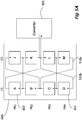
- FIG. 2A is a schematic block diagram showing a prior art solar array module 100 .
- Module 100 includes solar cells 102 physically arranged in rows ( R1 , R2 , R3 ) and columns ( C1 , C2 ). While three rows and two columns are shown, it should be appreciated that the description below is not limited to that particular size.
- Cells 102 are typically electrically connected in series as a string of cells 104. Cells 102 are all identically electrically oriented.
- the output voltage of the module is typically converted by a converter 106.
- the terms "solar cell” and “cell” are used herein interchangeably, meaning solar cell.
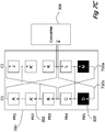
- FIG. 2C shows a solar module 120 with cells 102.
- Fig. 2C illustrates the solar modules as described in PCT Published Application No. WO/2011/089607 ('607) filed on January 23 rd , 2011 and PCT Published Application No. WO/2013/144963 ('963) filed on March 30 th , 2013, by the same inventor.
- Module 120 includes solar cells 102 physically arranged in a matrix of rows ( R1 , R2 , R3 , R4 ) and columns ( C1 , C2 ). While a matrix of four rows and two columns is shown, it should be appreciated that the description below is not limited to that particular matrix size.
- individual cells 102 are electrically connected in parallel by electrical connections 122 to create a crisscross electrical matrix.
- a plurality of cells connected in series and herein referred to as a serial unit 102 may be electrically connected in parallel to another serial unit.
- the crisscross electrical matrix may therefore include individual cells 102 or serial units 124.
- current I may flow along a variety of paths due to the crisscross electrical matrix.
- Fig. 2C current I is shown as flowing through cells M , L , K , and J as well as M , L , K , and A .
- the current will not be disrupted as there are alternative paths. Failure of other cells 102 will also minimally disrupt functioning of the module as long as an alternative path for current flow can be found.
- shading of an entire physical row R4 such as caused by the situation described above with reference to Fig. 1 , will lead to a loss of power in the entire module as all current flow I in the module will be disrupted.
- the present invention overcomes the deficiencies of the background art by providing a solar module according to claim 1 or to claim 8.
- the solar module includes solar cells arranged in a physical matrix of X ⁇ 2 rows and Y ⁇ 4 columns where the cells are electrically interconnected in an electrical crisscross matrix arranged in electrical rows and columns such that the electrical and physical matrices only partially overlap.
- a physical row that is fully shaded therefore does not result in a fully shaded electrical row, allowing current to continue flowing in the module.
- Other causes of reduced functionality due to one or more malfunctioning solar cells and/or due to obstruction of light are similarly overcome by the proposed arrangement.
- orientation related descriptions such as “top”, “bottom”, “horizontal”, “vertical” “up”, “upper”, “down”, “low”, “lower” and the like, assumes that the solar cell module is situated, with no limitations, such that the positive ("+”) side of the array is considered, artificially, with no limitations, as the top side of the array, and the negative ("-") side of the array is considered, artificially, with no limitations, as the bottom side of the array.
- the negative (“-") side of the array is considered, artificially, with no limitations, as the top side of the array
- the positive ("+" side of the array is considered, artificially, with no limitations, as the bottom side of the array.
- the terms “electrical” or “electrically wired”, as used herein refer to the electrical configuration of the matrix, regardless of the physical configuration of the solar cells in the solar panel.
- the term “physical” as used herein refers to the physical placement of solar cells in the module/panel, regardless of the electrical inter-wiring of the solar cells.
- a non-reconfigurable solar array module that is pre-configured to prevent electric blockage of the module, when at least one physical row of solar cells malfunctions.
- the solar array module includes a plurality of solar cells arranged in a matrix of physical rows and physical columns, electrical connections connecting the solar cells in each of the columns in series and electrical connections connecting a portion of the solar cells in parallel to form electrical rows of the solar cells, wherein the physical rows and the electrical rows only partially overlap.
- up to half of the physical rows and the electrical rows overlap.
- between 5% and 95% of the physical rows and the electrical rows overlap.
- the number of said columns is larger than the number of rows.
- the columns are divided into at least a first side and a second side.
- Each of the electrical rows includes at least one physical row of solar cells on said first side and is electrically connected to solar cells of a different physical row on said second side.
- the solar cells in the at least one physical row on said first side are connected in parallel and said solar cells in said at least one physical row on said second side are connected in parallel, wherein the solar cells in the at least one physical row of the first side are connected in parallel to the solar cells in the respective at least one physical row of the second side.
- the solar cells on the first side are physically inverted, polarity-wise, with respect to the solar cells on the second side.
- the solar array module includes X rows, wherein the solar cells of the adjacent columns of the first side and the second side are electrically connected by electrical cross connections.
- the electrical connections include connections from the negative side of the solar cell in the 1+ n th row of the first side adjacent column to the negative side of the cell in the X-n th row of the second side adjacent column, wherein n is an integer and 0 ⁇ n ⁇ X , and a connection from the positive side of the solar cell in the X h row of the first side adjacent column to the positive side of the cell in the 1 st row of the second side adjacent column.
- At least one of the solar cells is further electrically connected in series to at least one additional solar cell, to form a serial unit.
- the solar array module further includes a power converter selected from the group consisting of a DC/DC power converter, a DC/DC transformer and a combination thereof.
- the power converter includes a plurality of transistors for alternately connecting the opposite sides in a primary of a transformer to the matrix of solar cells, wherein the operational duty cycle of the transistors is constant and there is a dead time for preventing the fast transistors from conducting simultaneously between the switching time ON to OFF or OFF to ON of the transistor.
- the dead time is less than 8% of the duty cycle.
- the transistors are MOSFET transistors or other suitable type of fast switching transistors.
- a non-reconfigurable solar array module that is pre-configured to prevent electric blockage of the module, when at least one physical row of solar cells malfunctions.
- the solar array module includes a matrix of X physical rows and Y columns of solar cells, wherein the columns are divided into a first side numbering Y L columns and a second side numbering Y - Y L columns, where X ⁇ 2, Y ⁇ 4, Y L ⁇ 2 and Y - Y L ⁇ 2.
- Y L columns on the first side include solar cells that are physically inverted, polarity-wise, with respect to the solar cells on the second side.
- the solar cells in each of the columns are connected in series.
- Solar cells in each of the physical rows on the first side are electrically connected in parallel and solar cells in each of the physical rows on the second side are electrically connected in parallel, wherein the negative side of the solar cell in the 1+ n th physical row of column Y L is electrically connected to the negative side of the solar cell in the X- n th physical row of column Y L+1 , where n is an integer and 0 ⁇ n ⁇ X .
- the positive side of the solar cell in the X th physical row of column Y L is electrically connected to the positive side of the cell in the 1 st physical row of column Y L+1 .
- the solar array module further includes a power converter connected to the positive side of physical row 1 and the negative side of physical row X on the second side.
- a non-reconfigurable solar array module that is pre-configured to prevent electric blockage of the module, when at least one physical row of solar cells malfunctions.
- the solar array module that includes a matrix of X physical rows and Y columns of solar cells, wherein the columns are divided into a first side numbering Y L columns and a second side numbering Y - Y L columns, where X ⁇ 2, Y ⁇ 4, Y L ⁇ 2 and Y - Y L ⁇ 2.
- Y L columns on the first side include solar cells that are physically inverted, polarity-wise, with respect to the solar cells on the second side.
- the physical rows of the second side are sub divided into an upper section numbering X T physical rows, and a lower section numbering X - X T physical rows.
- the solar cells in each of the columns on the first side are connected in series, wherein the solar cells in each physical row on the first side are electrically connected in parallel.
- the solar cells in each of the columns in the upper section of the second side are connected in series, wherein the solar cells in each physical row of the upper section of the second side are electrically connected in parallel.
- the solar cells in each column of the lower section of the second side are connected in series, wherein the solar cells in each physical row of the lower section of the second side are electrically connected in parallel.
- the negative side of the solar cell in the 1+ n th physical row of column Y L is electrically connected to the negative side of the cell in the X T - n th physical row of column Y L+1 , where n is an integer and 0 ⁇ n ⁇ X T , and the positive side of the cell in the 1+ n th physical row of column Y L is electrically connected to the positive side of the cell in the X T - n th physical row of column Y L+1 .
- the negative side of the cell in the X T+ + n th physical row of column Y L is electrically connected to the negative side of the cell in the X- n th physical row of column Y L+1 , where n is an integer and X T+1 ⁇ n ⁇ X , and the positive side of the cell in the X th physical row of column Y L is electrically connected to the positive side of the cell in the X T+1 th physical row of column Y L+1 .
- the solar array module further includes a power converter connected to the positive side of physical row X T+1 on the second side and to the negative side of physical row X T on the second side.
- the solar array module further includes a power converter connected to the positive side of the X th physical row on the first side and to the negative side of the 1 st physical row on the first side.
- At least one of the solar cells is further electrically connected in series to at least one additional said solar cell, to form a serial unit.
- a non-reconfigurable solar array module that is pre-configured to prevent electric blockage of the module, when at least one physical row of solar cells malfunctions.
- the solar array module includes: a matrix of X physical rows and Y columns of solar cells, wherein the columns are divided into a first side numbering Y L columns into a second side numbering Y - Y L ; wherein Y L columns on the first side include cells that are physically inverted, polarity-wise, relative to the cells on the second side; wherein the physical rows of the second side are divided into an upper section numbering X T physical rows and a lower section numbering X - X T physical rows; wherein the cells in each of the columns on the first side are connected in series; wherein the cells in each physical row on the first side are electrically connected in parallel; wherein the cells in each of the columns in the upper section of the second side are connected in series; wherein the cells in each physical row of the upper section of the second side are electrically connected
- the solar array module further includes a power converter connected to the positive side of physical row X T+1 on the second side and to the negative side of physical row X T on the second side.
- An embodiment is an example or implementation of the invention.
- the various appearances of "one embodiment”, “an embodiment” or “some embodiments” do not necessarily all refer to the same embodiments.
- various features of the invention may be described in the context of a single embodiment, the features may also be provided separately or in any suitable combination. Conversely, although the invention may be described herein in the context of separate embodiments for clarity, the invention may also be implemented in a single embodiment.
- the present invention overcomes the deficiencies of the background art by providing a solar module with passive rerouting of electric current when an individual solar cell, part of a row of cells, or an entire row of cells malfunction.
- the solar module includes solar cells arranged in a physical matrix of rows and columns where the cells are electrically interconnected in an electrical crisscross matrix arranged in electrical rows and columns such that the electrical and physical matrices only partially overlap.
- a physical row that is fully shaded therefore does not result in a fully shaded electrical row, allowing current to continue flowing in the solar array module.
- Other causes of reduced functionality due to one or more malfunctioning solar cells and/or due to obstruction of light are similarly overcome by the proposed arrangement.
- solar array module 300 includes solar cells 302 physically arranged in a matrix of physical rows (PR1, PR2, and PR3) and columns ( C1 , C2 ).
- PR3 includes cells C and L. While a matrix of three rows and two columns is shown, it should be appreciated that the description below is not limited to that particular matrix size.
- Solar array module 300 is connected to a power DC/DC converter/transformer 306 which includes MOSFET transistors or other type of transistors arranged in a push-pull configuration, wherein the operational duty cycle of the transistors is constant and there is a dead time for preventing the fast transistors from conducting simultaneously between the switching time ON to OFF or OFF to ON of the transistors.
- a duty cycle that is just less than 50%, such as any of 48% or 49%, or 49.9% or other values between 42% and just below 50%, or between 43% and just below 50%, such as up to 49.9% and just below 50%.
- Fig. 3B is an alternate illustration of solar array module 300 of Fig. 3A .
- module 300 includes solar cells 302 electrically arranged in a matrix of electrical rows ( ER1 , ER2 , and ER3 ) and columns ( C1 , C2 ).
- ER3 includes cells A and L .
- the physical rows and electrical rows only partially overlap.
- the cells 302 in each column are connected in series and the cells 302 of each electrical row ( ER1 , ER2 , and ER3 ) are connected in parallel by crossing connections 310 such as 310a and 310b .
- the electrical matrix shown in Fig. 3B is thus a crisscross matrix.
- crossing connections 310 that are shown as intersecting one another (such as at point 312 in Fig. 3A ) do not make electrical contact. Junctions of electrical connection are shown as a black dot as at 314. This convention is consistent across all figures presented.
- connection 310a connects the negative side of cell A in PR1 to the negative side of cell L in PR3.
- current I can flow through any of the paths available. As shown in Fig. 3B , current I flows through all cells 302 and makes use of all crossing connections 310.
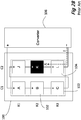
- Fig. 3C shows the physical layout of module 300 with physical row PR3 shaded or otherwise malfunctioning.
- Fig. 3D shows the illustration of Fig. 3B , illustrating the electrical row layout, with fully shaded physical row PR3 (with reference to Fig. 3C ).
- PR3 includes cells C and L which are shown as shaded in Fig. 3C and Fig. 3D . While the physical row PR3 is shaded, none of the electrical rows are fully shaded due to the differing partially overlapping physical and electrical matrix arrangements.
- current I passively routes around shaded cells C and L and flows through solar cells A , B , K and J .
- Each of the solar cells referred to in Figs. 3A-3D may optionally be a plurality of solar cells connected in series and referred to as a serial unit.
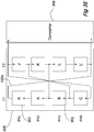
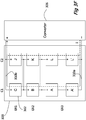
- the solar cells represented by A and L may include a serial unit of two or more solar cells connected in series. This is illustrated in Figs. 3E and 3F which show physical and electrical layouts respectively.
- Fig. 3E illustrates a physical matrix of 4 rows while Fig. 3F illustrates the same matrix but with 3 electrical rows as A and A' as well as L and L' are serial units of 2 cells each. Current I is shown as flowing through all available paths in Fig. 3F .
- Serial units may be utilized to reduce the amount and complexity of wiring needed in the solar array module. While a serial unit is shown as having two cells it should be appreciated that any number of cells may form a serial unit.
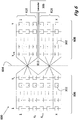
- Fig. 4 is an exemplary generic solar module according to at least some embodiments of the present invention.
- Fig. 4 is a generic illustration of the embodiment of Figs. 3A to 3D .
- a pre-configured, non-reconfigurable solar module 400 has X physical rows and Y columns of solar cells 302. References in the description of Fig. 4 are to physical rows and columns.
- cells 302 may be serial units of 2 or more solar cells electrically connected in series.
- the matrix is divided along a virtual vertical line 404 defining Y L columns to the left of line 404 and Y - Y L columns to the right of line 404 , where X ⁇ 2, Y ⁇ 4, Y L ⁇ 2 and Y-Y L ⁇ 2.
- the choice of where to split the matrix is based on the level of shade protection that is required for the solar array module depending on the likelihood of certain cells falling into shade.
- Y L columns on a first side 406 of the line 404 include cells 302 inverted polarity-wise relative to the cells 302 on the second side 408 of virtual line 404. That is, each solar cell 302 of the first side 406 is physically inverted with respect to the second side 408, such that the polarity of each solar cell 302 is inverted as shown in Fig. 4 : the "+" side of each cell 302 on the first side 406 is shown in at the lower side of each solar cell 302 , while the "+" side of each cell 302 on the second side 408 is shown in the upper side of each solar cell 302. It should be noted that electrical connectivity of solar module 400 remain a plain criss-cross matrix.
- Cells 302 in each physical row segment on the first side 406 are electrically connected in parallel.
- Cells 302 in each physical row segment on the second side 408 are electrically connected in parallel.
- the negative side of cell 302 in the 1+ n th row of column Y L is electrically connected to the negative side of cell 302 in the X- n th row of column Y L+1 where n is an integer and 0 ⁇ n ⁇ X .
- the positive side of cell 302 in the X th row of column Y L is electrically connected to the positive side of cell 302 in the 1 st row of column Y L+1 ;
- a power converter 306 may be connected to the positive side of row 1 and the negative side of row X on the second side 408.
- power converter 306 may be connected to the positive side of physical row X on first side 406 and to the negative side of the 1 st physical row on the first side 406.
- module 500 includes solar cells 302 physically arranged in a matrix of physical rows ( PR1 , PR2 , PR3 , and PR4 ) and columns ( C1 , C2 ).
- PR3 includes cells C and L. While a matrix of four rows and two columns is shown, it should be appreciated the description below is not limited to that particular matrix size.
- the solar array module is connected to a power DC/DC converter/transformer 306 as described above.
- Fig. 5B is an alternate illustration of the solar array module 500 of Fig. 5A .
- module 500 includes solar cells 302 electrically arranged in a matrix of electrical rows ( ER1 , ER2 , ER3 , and ER4 ) and columns ( C1 , C2 ).
- ER3 includes cells C and M .
- the embodiment of Figs. 5A-5C differs from that of Figs. 3A-3C in that the electrical matrix is divided into two crisscross matrices. Each crisscross matrix includes an equal number of rows.
- electrical rows ER1 and ER2 represent one crisscross matrix and rows ER3 and ER4 represent a second crisscross matrix.
- Cells B and C are electrically connected to join the two crisscross matrices.
- the crisscross matrices are formed by crossing connections 510 such as 510a and 510b .
- connection 510a connects the negative side of cell C in PR3 to the negative side of cell M in PR4.
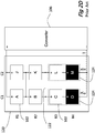
- Fig. 5C shows the physical layout of module 500 with physical row PR4 shaded.
- Fig. 5D shows the illustration of Fig. 5B , illustrating the electrical row layout, with fully shaded physical row PR4 (with reference to Fig. 5C ).
- PR4 includes cells D and M which are shown as shaded in Figs. 5C and 5D . While the physical row PR4 is shaded none of the electrical rows are fully shaded due to the differing partially overlapping physical and electrical matrix arrangements.
- current I passively routes around shaded cells D and M and flows through cells L , C , B , A and also through J , and K.
- Each of the solar cells referred to in Figs. 5A-5D may optionally be a plurality of solar cells connected in series and referred to as a serial unit.
- the solar cell represented by "A" may include a serial unit of two or more solar cells connected in series.
- Fig. 6 is an exemplary generic solar module according to at least some embodiments of the present invention.
- Fig. 6 is a generic illustration of the embodiment of Figs. 5A to 5C .
- a pre-configured, non-reconfigurable solar module 600 has X physical rows and Y columns of solar cells 302. References in the description of Fig. 6 are to physical rows and columns.
- cells 302 may be serial units of 2 or more cells.
- the matrix is divided along a virtual vertical line 604 defining Y L columns to the left of line 604 and Y - Y L columns to the right of line 604 , where X ⁇ 2, Y ⁇ 4, Y L ⁇ 2 and Y-Y L ⁇ 2.
- the choice of where to split the matrix is based on the level of shade protection that is required for the solar array module depending on the likelihood of certain cells falling into shade.
- Y L columns on a first side 606 of the line 604 include cells 302 inverted polarity-wise relative to the cells 302 on the second side 608 of virtual line 604. That is, each solar cell 302 of the first side 606 is physically inverted with respect to the second side 608 , such that the polarity of each solar cell 302 is inverted as shown in Fig. 6 : the "+" side of each cell 302 on the first side 606 is shown in at the lower side of each solar cell 302 , while the "+" side of each cell 302 on the second side 608 is shown in the upper side of each solar cell 302. It should be noted that electrical connectivity of solar module 600 remain a plain criss-cross matrix.
- the matrix of second side 608 is divided along a virtual horizontal line 612 defining X T physical rows above the line and X - X T physical rows below the line where physical rows X T and X T+1 are adjacent physical rows on either side of line 612.
- Cells 302 in every column on first side 606 are connected in series.
- Cells 302 in each physical row on the first side 606 are electrically connected in parallel.
- Cells 302 in each physical row of the upper section 618 of second side 608 are electrically connected in parallel.
- Cells 302 in each physical row of the lower section 616 of second side 608 are electrically connected in parallel.
- the negative side of cell 302 in the 1+ n th physical row of column Y L is electrically connected to the negative side of cell 302 in the X T - n th physical row of column Y L+1 where n is an integer and 0 ⁇ n ⁇ X T .
- the positive side of cell 302 in the X T th physical row of column Y L is electrically connected to the positive side of cell 302 in the 1 ST physical row of column Y L+1 .
- the negative side of cell 302 in the X T+1 + n th physical row of column Y L is electrically connected to the negative side of cell 302 in the X- n th physical row of column Y L+1 where n is an integer and X T+1 ⁇ n ⁇ X .
- the positive side of cell 302 in the X th physical row of column Y L is electrically connected to the positive side of cell 302 in the X T+1 th physical row of column Y L+1 .
- power converter 306 may be connected to the positive side of physical row X T+1 on second side 608 and to the negative side of physical row X T on the second side 608.
- power converter 306 may be connected to the positive side of physical row X on first side 606 and to the negative side of the 1 st physical row on the first side 606.
- Figs. 7A-7D are exemplary schematic illustrations of a pre-configured, non-reconfigurable solar module 700 according to at least some embodiments of the present invention.
- module 700 includes solar cells 302 physically arranged in a matrix of physical rows ( PR1 , PR2 , PR3, PR4, and PR5 ) and columns ( C1 , C2 ).
- PR4 includes cells C and L.
- Figs. 7A-7D illustrate the inclusion of serial units having two solar cells ( A and A ', and K and K '). While a matrix of five rows and two columns is shown it should be appreciated that any size matrix may be provided and the description below is not limited to that particular matrix size.
- the size of a serial unit shown is 2 cells but the serial unit may include any number of cells.
- the solar array module is connected to a power DC/DC converter/transformer 306 as described above.
- Fig. 7B is an alternate illustration of the solar array module 700 of Fig. 7A .
- module 700 includes solar cells 302 electrically arranged in a matrix of four electrical rows ( ER1 , ER2 , ER3 , and ER4 ) and columns ( C1 , C2 ).
- ER1 is only one electrical row as it includes serial unit connected in parallel.
- ER1 includes serial units A ( A and A' ) and K ( K and K' ).
- the electrical matrix is divided into two crisscross matrices.
- rows ER1 and ER2 represent one crisscross matrix and rows ER3 and ER4 represent a second crisscross matrix.
- Cells B and C are electrically connected to join the two crisscross matrices.
- the crisscross matrices are formed by crossing connections 710 such as 710a and 710b.
- connection 710a connects the negative side of cell C in PR4 to the negative side of cell M in PR5 ( Fig. 7A ).
- Fig. 7C shows the physical layout of module 700 with physical row PR5 shaded.
- Fig. 7D shows the illustration of Fig. 7B , illustrating the electrical row layout, with a fully shaded physical row PR5 (with reference to Fig. 7C ).
- PR5 includes cells D and M which are shown as shaded in Figs. 7C and 7D . While the physical row PR5 is shaded, none of the electrical rows ( ER3 or ER4 of Fig. 7D ) are fully shaded due to the differing partially overlapping physical and electrical matrix arrangements.
- current I passively routes around shaded cells D and M and flows through cells L , C , B , A , A ' and also through J , K , and K'.
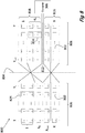
- Fig. 8 is an exemplary generic solar module according to at least some embodiments of the present invention.
- Fig. 8 is a generic illustration of the embodiment of Figs. 7A-7D .
- a pre-configured, non-reconfigurable solar module 800 has X physical rows and Y columns of solar cells 302. References in the description of Fig. 8 are to physical rows and columns.
- the matrix is divided along a virtual vertical line 804 defining Y L columns to the left of line 804 and Y - Y L columns to the right of line 804 , where X ⁇ 2, Y ⁇ 4, Y L ⁇ 2 and Y-Y L ⁇ 2.
- the choice of where to split the matrix is based on the level of shade protection that is required for the solar array module depending on the likelihood of certain cells falling into shade;
- Y L columns on a first side 806 of the line 804 include cells 302 inverted, in terms of polarity, relative to the cells 302 on the second side 808 of virtual line 804. That is, each solar cell 302 of the first side 806 is physically inverted with respect to the second side 808 , such that the polarity of each solar cell 302 is inverted as shown in Fig. 4 : the "+" side of each cell 302 on the first side 806 is shown in at the lower side of each solar cell 302 , while the "+" side of each cell 302 on the second side 808 is shown in the upper side of each solar cell 302. It should be noted that electrical connectivity of solar module 800 remain a plain criss-cross matrix.
- the matrix of second side 808 is divided along a virtual horizontal line 812 defining X T physical rows above the line and X - X T physical rows below the line where physical rows X T and X T+1 are adjacent physical rows on either side of line 812.
- Cells 302 in physical rows X T to X on the first side 806 are electrically connected in parallel, wherein physical row X T includes serial units 824 , having, in this example, 2 solar cells 302 in each column.
- Cells 302 in physical row 1 of the upper section 818 of second side 808 are electrically connected in parallel, wherein solar cells 302 are arranged in serial units 824 , having, in this example, 2 solar cells 302 in each column.
- Cells 302 in each physical row of the lower section 816 of second side 808 are electrically connected in parallel.
- the negative side of serial unit 824 in the 1 st physical row of column Y L is electrically connected to the negative side of serial unit 824 in the X T th physical row of column Y L+1 .
- the positive side of serial unit 824 in the 1 st physical row of column Y L is electrically connected to the positive side of serial unit 824 in the X T th physical row of column Y L+1 .
- the negative side of cell 302 in the X T th physical row of column Y L is electrically connected to the negative side of cell 302 in the 1 st physical row of column Y L+1 .
- the negative side of cell 302 in the X T+1 + n th physical row of column Y L is electrically connected to the negative side of cell 302 in the X- n th physical row of column Y L+1 where n is an integer and X T+1 ⁇ n ⁇ X .
- the positive side of cell 302 in the X th physical row of column Y L is electrically connected to the positive side of cell 302 in the X T +1 th physical row of column Y L+1 .
- power converter 306 is connected to the positive side of physical row X T+1 on second side 808 and to the negative side of physical row X T on the second side 808.
- power converter 306 is connected to the positive side of physical row X on first side 806 and to the negative side of the 1 st physical row on the first side 806.
Landscapes
- Engineering & Computer Science (AREA)
- Power Engineering (AREA)
- Photovoltaic Devices (AREA)
- Life Sciences & Earth Sciences (AREA)
- Sustainable Development (AREA)
- Sustainable Energy (AREA)
- Direct Current Feeding And Distribution (AREA)
- Dc-Dc Converters (AREA)
Description
- The present invention relates to a solar array module system for generating electric-power and more particularly, to a solar array module system facilitated to maximize the power generation from a solar module, configured to maximize the power generation from a plurality of solar cells, interconnected in a matrix configuration in a light obstruction situation.
- Photovoltaic cells have been widely used in a variety of applications to generate convenient electricity. Typically, a single solar cell produces an output voltage of around 0.5V, and a plurality of solar cells, typically, with no limitations, that are Silicon based, is conventionally connected in series to provide higher voltage levels.
- A solar array system includes solar array modules, wherein each solar array module includes a multiplicity of solar cells. The solar modules are typically tilted towards the sun. However, when the angle of the sun is very low and a front module may cast a shadow on a portion of a neighboring module that is positioned behind the front module, typically on the lower rows of solar cells of the solar-array module. Light may also be blocked or obstructed due to snow, buildings, billboards that typically cast a shadow on one side of the solar-array module. Thereby, the light obstruction causes a substantial reduction in the production yield of the module.
- Reference is now made to
Fig. 1 showing a prior art geometry of tilted solar modules of a solar-array module 100, tilted at an angle β. In this example, solar-array module array module 100a is positioned in front of solar-array module 100b, with respect to the sun. When the sun is at a pitch angle of α above the horizon, solar-array module 100a having a length l , casts a shadow on the ground surface with a displacement of d. No shadow is cast over solar-array module 100b. But, when the sun is at a lower pitch angle than α , such as a2 , solar-array module 100a casts a shadow over the lower section of solar-array module 100b. In this example, solar-array module 100a casts a shadow on the region delimited between P0 and P2 of solar-array module 100b, while only the solar cells disposed between P2 and P1 produce electric power. - Reference is also made to
Fig. 2A which is a schematic block diagram showing a prior artsolar array module 100.Module 100 includessolar cells 102 physically arranged in rows (R1, R2, R3) and columns (C1, C2). While three rows and two columns are shown, it should be appreciated that the description below is not limited to that particular size.Cells 102 are typically electrically connected in series as a string ofcells 104.Cells 102 are all identically electrically oriented. The output voltage of the module is typically converted by aconverter 106. It should be noted the terms "solar cell" and "cell" are used herein interchangeably, meaning solar cell. - In normal operation, current I is shown as flowing through string of
cells 104. In case of a failure of asingle cell 102 in astring 104, the current instring 104 will be disrupted. This is illustrated inFig. 2B , where cell K is shown as malfunctioning or shaded and preventing current I from flowing. Prior art modules may also use diodes or active switching means to bypass malfunctioning cells, but these add cost and complexity. - Reference is now made to
Fig. 2C , which shows asolar module 120 withcells 102.Fig. 2C illustrates the solar modules as described in PCT Published Application No.WO/2011/089607 WO/2013/144963 -
Module 120 includessolar cells 102 physically arranged in a matrix of rows (R1, R2, R3, R4) and columns (C1, C2). While a matrix of four rows and two columns is shown, it should be appreciated that the description below is not limited to that particular matrix size. Inmodule 120,individual cells 102 are electrically connected in parallel byelectrical connections 122 to create a crisscross electrical matrix. Optionally, a plurality of cells connected in series and herein referred to as aserial unit 102, may be electrically connected in parallel to another serial unit. The crisscross electrical matrix may therefore includeindividual cells 102 orserial units 124. - In normal operation, current I may flow along a variety of paths due to the crisscross electrical matrix. In
Fig. 2C current I is shown as flowing through cells M, L, K, and J as well as M, L, K, and A. In case of a failure of asingle cell 102 inmodule 120, the current will not be disrupted as there are alternative paths. Failure ofother cells 102 will also minimally disrupt functioning of the module as long as an alternative path for current flow can be found. However, as illustrated inFig. 2D , shading of an entire physical row R4, such as caused by the situation described above with reference toFig. 1 , will lead to a loss of power in the entire module as all current flow I in the module will be disrupted. - There is therefore a need and it would be advantageous to have a solar-array module able to maximize the power generated and prevent electrical failure of the module when an individual cell, part of a row of cells, or an entire row of cells malfunction. Such reduced functionality may be due to one or more malfunctioned solar cells, and/or due to obstruction of light from reaching at least a portion of one or more rows of solar cells. It would be further preferable to provide a module that was not dependent on an active switching or bypass mechanism.
- The present invention overcomes the deficiencies of the background art by providing a solar module according to
claim 1 or to claim 8. The solar module includes solar cells arranged in a physical matrix of X≥2 rows and Y≥4 columns where the cells are electrically interconnected in an electrical crisscross matrix arranged in electrical rows and columns such that the electrical and physical matrices only partially overlap. A physical row that is fully shaded therefore does not result in a fully shaded electrical row, allowing current to continue flowing in the module. Other causes of reduced functionality due to one or more malfunctioning solar cells and/or due to obstruction of light are similarly overcome by the proposed arrangement. - It should be noted that orientation related descriptions such as "top", "bottom", "horizontal", "vertical" "up", "upper", "down", "low", "lower" and the like, assumes that the solar cell module is situated, with no limitations, such that the positive ("+") side of the array is considered, artificially, with no limitations, as the top side of the array, and the negative ("-") side of the array is considered, artificially, with no limitations, as the bottom side of the array. Alternatively, with no limitations, the negative ("-") side of the array is considered, artificially, with no limitations, as the top side of the array, and the positive ("+") side of the array is considered, artificially, with no limitations, as the bottom side of the array.
- It should be further noted that the terms "electrical" or "electrically wired", as used herein refer to the electrical configuration of the matrix, regardless of the physical configuration of the solar cells in the solar panel. Similarly, it should be further noted that the term "physical" as used herein refers to the physical placement of solar cells in the module/panel, regardless of the electrical inter-wiring of the solar cells.
- According to some embodiments of the present invention, a non-reconfigurable solar array module that is pre-configured to prevent electric blockage of the module, when at least one physical row of solar cells malfunctions. The solar array module includes a plurality of solar cells arranged in a matrix of physical rows and physical columns, electrical connections connecting the solar cells in each of the columns in series and electrical connections connecting a portion of the solar cells in parallel to form electrical rows of the solar cells, wherein the physical rows and the electrical rows only partially overlap. Optionally, with no limitations, up to half of the physical rows and the electrical rows overlap. Optionally, between 5% and 95% of the physical rows and the electrical rows overlap. Preferably, with no limitations, the number of said columns is larger than the number of rows.
- The columns are divided into at least a first side and a second side. Each of the electrical rows includes at least one physical row of solar cells on said first side and is electrically connected to solar cells of a different physical row on said second side. The solar cells in the at least one physical row on said first side are connected in parallel and said solar cells in said at least one physical row on said second side are connected in parallel, wherein the solar cells in the at least one physical row of the first side are connected in parallel to the solar cells in the respective at least one physical row of the second side.
- The solar cells on the first side are physically inverted, polarity-wise, with respect to the solar cells on the second side.
- Preferably, the solar array module includes X rows, wherein the solar cells of the adjacent columns of the first side and the second side are electrically connected by electrical cross connections. Preferably, the electrical connections include connections from the negative side of the solar cell in the 1+ n th row of the first side adjacent column to the negative side of the cell in the X-n th row of the second side adjacent column, wherein n is an integer and 0≤ n < X , and a connection from the positive side of the solar cell in the X h row of the first side adjacent column to the positive side of the cell in the 1st row of the second side adjacent column.
- Optionally at least one of the solar cells is further electrically connected in series to at least one additional solar cell, to form a serial unit.
- Preferably the solar array module further includes a power converter selected from the group consisting of a DC/DC power converter, a DC/DC transformer and a combination thereof. Preferably, the power converter includes a plurality of transistors for alternately connecting the opposite sides in a primary of a transformer to the matrix of solar cells, wherein the operational duty cycle of the transistors is constant and there is a dead time for preventing the fast transistors from conducting simultaneously between the switching time ON to OFF or OFF to ON of the transistor. Preferably the dead time is less than 8% of the duty cycle. Optionally, the transistors are MOSFET transistors or other suitable type of fast switching transistors.
- According to a further embodiment of the present invention, a non-reconfigurable solar array module that is pre-configured to prevent electric blockage of the module, when at least one physical row of solar cells malfunctions. The solar array module includes a matrix of X physical rows and Y columns of solar cells, wherein the columns are divided into a first side numbering Y L columns and a second side numbering Y-Y L columns, where X ≥2, Y ≥4, Y L ≥2 and Y - Y L ≥2. Y L columns on the first side include solar cells that are physically inverted, polarity-wise, with respect to the solar cells on the second side. The solar cells in each of the columns are connected in series. Solar cells in each of the physical rows on the first side are electrically connected in parallel and solar cells in each of the physical rows on the second side are electrically connected in parallel, wherein the negative side of the solar cell in the 1+ n th physical row of column Y L is electrically connected to the negative side of the solar cell in the X-n th physical row of column Y L+1, where n is an integer and 0≤ n <X. The positive side of the solar cell in the X th physical row of column Y L is electrically connected to the positive side of the cell in the 1st physical row of column Y L+1. Preferably, the solar array module further includes a power converter connected to the positive side of
physical row 1 and the negative side of physical row X on the second side. - According to a further embodiment of the present invention, a non-reconfigurable solar array module that is pre-configured to prevent electric blockage of the module, when at least one physical row of solar cells malfunctions. The solar array module that includes a matrix of X physical rows and Y columns of solar cells, wherein the columns are divided into a first side numbering Y L columns and a second side numbering Y-Y L columns, where X ≥2, Y ≥4, Y L ≥2 and Y-Y L ≥2. Y L columns on the first side include solar cells that are physically inverted, polarity-wise, with respect to the solar cells on the second side. The physical rows of the second side are sub divided into an upper section numbering X T physical rows, and a lower section numbering X-X T physical rows. The solar cells in each of the columns on the first side are connected in series, wherein the solar cells in each physical row on the first side are electrically connected in parallel. The solar cells in each of the columns in the upper section of the second side are connected in series, wherein the solar cells in each physical row of the upper section of the second side are electrically connected in parallel. The solar cells in each column of the lower section of the second side are connected in series, wherein the solar cells in each physical row of the lower section of the second side are electrically connected in parallel. The negative side of the solar cell in the 1+ n th physical row of column Y L is electrically connected to the negative side of the cell in the X T- n th physical row of column Y L+1, where n is an integer and 0≤ n <X T, and the positive side of the cell in the 1+ n th physical row of column Y L is electrically connected to the positive side of the cell in the X T- n th physical row of column Y L+1. The negative side of the cell in the X T++ n th physical row of column Y L is electrically connected to the negative side of the cell in the X-n th physical row of column Y L+1, where n is an integer and X T+1< n <X, and the positive side of the cell in the X th physical row of column Y L is electrically connected to the positive side of the cell in the X T+1 th physical row of column Y L+1.
- Optionally, the solar array module further includes a power converter connected to the positive side of physical row X T+1 on the second side and to the negative side of physical row X T on the second side. Alternatively, the solar array module further includes a power converter connected to the positive side of the X th physical row on the first side and to the negative side of the 1st physical row on the first side.
- Optionally, at least one of the solar cells is further electrically connected in series to at least one additional said solar cell, to form a serial unit.
- According to a further embodiment of the present invention, a non-reconfigurable solar array module that is pre-configured to prevent electric blockage of the module, when at least one physical row of solar cells malfunctions. The solar array module includes: a matrix of X physical rows and Y columns of solar cells, wherein the columns are divided into a first side numbering Y L columns into a second side numbering Y-Y L; wherein Y L columns on the first side include cells that are physically inverted, polarity-wise, relative to the cells on the second side; wherein the physical rows of the second side are divided into an upper section numbering X T physical rows and a lower section numbering X-X T physical rows; wherein the cells in each of the columns on the first side are connected in series; wherein the cells in each physical row on the first side are electrically connected in parallel; wherein the cells in each of the columns in the upper section of the second side are connected in series; wherein the cells in each physical row of the upper section of the second side are electrically connected in parallel; wherein the cells in each column of the lower section of the second side are connected in series; wherein the cells in each physical row of the lower section of the second side are electrically connected in parallel; wherein the negative side of the cell in the 1st physical row of column Y L is electrically connected to the negative side of the cell in the X T th physical row of column Y L+1; wherein the positive side of the cell in the X T th physical row of column Y L is electrically connected to the positive side of the cell in the 1st physical row of column Y L+1; wherein the negative side of the cell in the X T th physical row of column Y L is electrically connected to the negative side of cell in the 1st physical row of column Y L+1; wherein the negative side of the cell in the X T+1+ n th physical row of column Y L is electrically connected to the negative side of the cell in the X-n th physical row of column Y L+1 where n is an integer and XT+1< n <X; and wherein the positive side of the cell in the X th physical row of column Y L is electrically connected to the positive side of the cell in the X T+1 th physical row of column Y L+1 .
- Preferably, the solar array module further includes a power converter connected to the positive side of physical row X T+1 on the second side and to the negative side of physical row X T on the second side.
- An embodiment is an example or implementation of the invention. The various appearances of "one embodiment", "an embodiment" or "some embodiments" do not necessarily all refer to the same embodiments. Although various features of the invention may be described in the context of a single embodiment, the features may also be provided separately or in any suitable combination. Conversely, although the invention may be described herein in the context of separate embodiments for clarity, the invention may also be implemented in a single embodiment.
- Reference in the specification to "one embodiment", "an embodiment", "some embodiments" or "other embodiments" means that a particular feature, structure, or characteristic described in connection with the embodiments is included in at least one embodiment, but not necessarily all embodiments of the invention. It is understood that the phraseology and terminology employed herein is not to be construed as limiting and are for descriptive purposes only.
- Unless otherwise defined, all technical and scientific terms used herein have the same meaning as commonly understood by one of average skill in the art to which the present invention belongs. The methods and examples provided herein are illustrative only, and are not intended to be limiting.
- The present invention will become fully understood from the detailed description given herein below and the accompanying drawings, which are given by way of illustration and example only, and thus not limiting in any way, wherein:
-
Fig. 1 is a schematic illustration showing the geometry of tilted solar array modules of a prior art solar-system; -
Figs. 2A-2B are schematic diagrams of prior art solar cell modules in non-shaded and shaded conditions; -
Figs. 3A-3F are schematic physical and electrical diagrams of a solar cell module in non-shaded and shaded conditions according to some embodiments of the present invention; -
Fig. 4 is a generic schematic diagram of a solar cell module according to some embodiments of the present invention; -
Figs. 5A-5D are schematic physical and electrical diagrams of a solar cell module in non-shaded and shaded conditions according to some embodiments of the present invention; -
Fig. 6 is a generic schematic diagram of a solar cell module according to some embodiments of the present invention; -
Figs. 7A-7D are schematic physical and electrical diagrams of a solar cell module in non-shaded and shaded conditions according to some embodiments of the present invention; and -
Fig. 8 is a generic schematic diagram of a solar cell module according to some embodiments of the present invention. - The present invention now will be described more fully hereinafter with reference to the accompanying drawings, in which preferred embodiments of the invention are shown.
- The present invention overcomes the deficiencies of the background art by providing a solar module with passive rerouting of electric current when an individual solar cell, part of a row of cells, or an entire row of cells malfunction. The solar module includes solar cells arranged in a physical matrix of rows and columns where the cells are electrically interconnected in an electrical crisscross matrix arranged in electrical rows and columns such that the electrical and physical matrices only partially overlap. A physical row that is fully shaded therefore does not result in a fully shaded electrical row, allowing current to continue flowing in the solar array module. Other causes of reduced functionality due to one or more malfunctioning solar cells and/or due to obstruction of light are similarly overcome by the proposed arrangement.
- Reference is now made to
Figs. 3A-3F showing exemplary schematic illustrations of a pre-configured, non-reconfigurablesolar module 300 according to at least some embodiments of the present invention. As shown inFig. 3A ,solar array module 300 includessolar cells 302 physically arranged in a matrix of physical rows (PR1, PR2, and PR3) and columns (C1, C2). For example, PR3 includes cells C and L. While a matrix of three rows and two columns is shown, it should be appreciated that the description below is not limited to that particular matrix size. -
Solar array module 300 is connected to a power DC/DC converter/transformer 306 which includes MOSFET transistors or other type of transistors arranged in a push-pull configuration, wherein the operational duty cycle of the transistors is constant and there is a dead time for preventing the fast transistors from conducting simultaneously between the switching time ON to OFF or OFF to ON of the transistors. This, yields a duty cycle that is just less than 50%, such as any of 48% or 49%, or 49.9% or other values between 42% and just below 50%, or between 43% and just below 50%, such as up to 49.9% and just below 50%. -
Fig. 3B is an alternate illustration ofsolar array module 300 ofFig. 3A . As shown inFig. 3B ,module 300 includessolar cells 302 electrically arranged in a matrix of electrical rows (ER1, ER2, and ER3) and columns (C1, C2). For example, ER3 includes cells A and L. Thus the physical rows and electrical rows only partially overlap. In the electrical matrix thecells 302 in each column are connected in series and thecells 302 of each electrical row (ER1, ER2, and ER3) are connected in parallel by crossing connections 310 such as 310a and 310b. The electrical matrix shown inFig. 3B is thus a crisscross matrix. For the sake of clarity, it should be noted that crossing connections 310 that are shown as intersecting one another (such as atpoint 312 inFig. 3A ) do not make electrical contact. Junctions of electrical connection are shown as a black dot as at 314. This convention is consistent across all figures presented. - Referring back to
Fig. 3A , in order to implement the electrical crisscross matrix ofFig. 3B , cells A, B, and C of column C1 are physically inverted, polarity-wise, with respect to cells J, K, and L of column C2. Additionally, crossing connections 310 extend across physical rows. For example,connection 310a connects the negative side of cell A in PR1 to the negative side of cell L in PR3. - In operation, current I can flow through any of the paths available. As shown in
Fig. 3B , current I flows through allcells 302 and makes use of all crossing connections 310. -
Fig. 3C shows the physical layout ofmodule 300 with physical row PR3 shaded or otherwise malfunctioning.Fig. 3D shows the illustration ofFig. 3B , illustrating the electrical row layout, with fully shaded physical row PR3 (with reference toFig. 3C ). PR3 includes cells C and L which are shown as shaded inFig. 3C andFig. 3D . While the physical row PR3 is shaded, none of the electrical rows are fully shaded due to the differing partially overlapping physical and electrical matrix arrangements. As shown inFig. 3D , current I passively routes around shaded cells C and L and flows through solar cells A, B, K and J. - Each of the solar cells referred to in
Figs. 3A-3D may optionally be a plurality of solar cells connected in series and referred to as a serial unit. For example, the solar cells represented by A and L may include a serial unit of two or more solar cells connected in series. This is illustrated inFigs. 3E and3F which show physical and electrical layouts respectively.Fig. 3E illustrates a physical matrix of 4 rows whileFig. 3F illustrates the same matrix but with 3 electrical rows as A and A' as well as L and L' are serial units of 2 cells each. Current I is shown as flowing through all available paths inFig. 3F . - Serial units may be utilized to reduce the amount and complexity of wiring needed in the solar array module. While a serial unit is shown as having two cells it should be appreciated that any number of cells may form a serial unit.
-
Fig. 4 is an exemplary generic solar module according to at least some embodiments of the present invention.Fig. 4 is a generic illustration of the embodiment ofFigs. 3A to 3D . As shown inFig. 4 , a pre-configured, non-reconfigurablesolar module 400 has X physical rows and Y columns ofsolar cells 302. References in the description ofFig. 4 are to physical rows and columns. As above,cells 302 may be serial units of 2 or more solar cells electrically connected in series. - The matrix is divided along a virtual
vertical line 404 defining Y L columns to the left ofline 404 and Y-Y L columns to the right ofline 404, where X ≥2, Y ≥4, Y L ≥2 and Y-Y L ≥2. The choice of where to split the matrix is based on the level of shade protection that is required for the solar array module depending on the likelihood of certain cells falling into shade. - YL columns on a
first side 406 of theline 404 includecells 302 inverted polarity-wise relative to thecells 302 on thesecond side 408 ofvirtual line 404. That is, eachsolar cell 302 of thefirst side 406 is physically inverted with respect to thesecond side 408, such that the polarity of eachsolar cell 302 is inverted as shown inFig. 4 : the "+" side of eachcell 302 on thefirst side 406 is shown in at the lower side of eachsolar cell 302, while the "+" side of eachcell 302 on thesecond side 408 is shown in the upper side of eachsolar cell 302. It should be noted that electrical connectivity ofsolar module 400 remain a plain criss-cross matrix. -
Cells 302 in every column are connected in series. -
Cells 302 in each physical row segment on thefirst side 406 are electrically connected in parallel. -
Cells 302 in each physical row segment on thesecond side 408 are electrically connected in parallel. - The negative side of
cell 302 in the 1+ n th row of column Y L is electrically connected to the negative side ofcell 302 in the X-n th row of column Y L+1 where n is an integer and 0< n <X. - The positive side of
cell 302 in the X th row of column Y L is electrically connected to the positive side ofcell 302 in the 1st row of column Y L+1; and - Optionally, as shown in
Fig. 4 , apower converter 306 may be connected to the positive side ofrow 1 and the negative side of row X on thesecond side 408. Alternatively,power converter 306 may be connected to the positive side of physical row X onfirst side 406 and to the negative side of the 1st physical row on thefirst side 406. - Reference is now made to
Figs. 5A-5D which are exemplary schematic illustrations of a pre-configured, non-reconfigurablesolar module 500 according to at least some embodiments of the present invention. As shown inFig. 5A ,module 500 includessolar cells 302 physically arranged in a matrix of physical rows (PR1, PR2, PR3, and PR4) and columns (C1, C2). For example, PR3 includes cells C and L. While a matrix of four rows and two columns is shown, it should be appreciated the description below is not limited to that particular matrix size. The solar array module is connected to a power DC/DC converter/transformer 306 as described above. -
Fig. 5B is an alternate illustration of thesolar array module 500 ofFig. 5A . As shown inFig. 5B ,module 500 includessolar cells 302 electrically arranged in a matrix of electrical rows (ER1, ER2, ER3, and ER4) and columns (C1, C2). For example, ER3 includes cells C and M. Thus the physical rows and electrical rows only partially overlap. The embodiment ofFigs. 5A-5C differs from that ofFigs. 3A-3C in that the electrical matrix is divided into two crisscross matrices. Each crisscross matrix includes an equal number of rows. As shown, electrical rows ER1 and ER2 represent one crisscross matrix and rows ER3 and ER4 represent a second crisscross matrix. Cells B and C are electrically connected to join the two crisscross matrices. The crisscross matrices are formed by crossing connections 510 such as 510a and 510b. - Referring back to
Fig. 5A , in order to implement the electrical crisscross matrices ofFig. 5B , cells A, B, C, and D of column C1 are physically inverted, polarity-wise, with respect to cells J, K, L, and M of column C2. Additionally, crossing connections 510 extend across physical rows. For example,connection 510a connects the negative side of cell C in PR3 to the negative side of cell M in PR4. - In operation, current I can flow through any of the paths available, as shown in
Fig. 5B . -
Fig. 5C shows the physical layout ofmodule 500 with physical row PR4 shaded.Fig. 5D shows the illustration ofFig. 5B , illustrating the electrical row layout, with fully shaded physical row PR4 (with reference toFig. 5C ). PR4 includes cells D and M which are shown as shaded inFigs. 5C and5D . While the physical row PR4 is shaded none of the electrical rows are fully shaded due to the differing partially overlapping physical and electrical matrix arrangements. As shown inFig. 5D , current I passively routes around shaded cells D and M and flows through cells L, C, B, A and also through J, and K. - Each of the solar cells referred to in
Figs. 5A-5D may optionally be a plurality of solar cells connected in series and referred to as a serial unit. For example, the solar cell represented by "A" may include a serial unit of two or more solar cells connected in series. -
Fig. 6 is an exemplary generic solar module according to at least some embodiments of the present invention.Fig. 6 is a generic illustration of the embodiment ofFigs. 5A to 5C . As shown inFig. 6 , a pre-configured, non-reconfigurablesolar module 600 has X physical rows and Y columns ofsolar cells 302. References in the description ofFig. 6 are to physical rows and columns. As above,cells 302 may be serial units of 2 or more cells. - The matrix is divided along a virtual
vertical line 604 defining Y L columns to the left ofline 604 and Y-Y L columns to the right ofline 604, where X ≥2, Y ≥4, Y L ≥2 and Y-Y L ≥2. The choice of where to split the matrix is based on the level of shade protection that is required for the solar array module depending on the likelihood of certain cells falling into shade. - Y L columns on a
first side 606 of theline 604 includecells 302 inverted polarity-wise relative to thecells 302 on thesecond side 608 ofvirtual line 604. That is, eachsolar cell 302 of thefirst side 606 is physically inverted with respect to thesecond side 608, such that the polarity of eachsolar cell 302 is inverted as shown inFig. 6 : the "+" side of eachcell 302 on thefirst side 606 is shown in at the lower side of eachsolar cell 302, while the "+" side of eachcell 302 on thesecond side 608 is shown in the upper side of eachsolar cell 302. It should be noted that electrical connectivity ofsolar module 600 remain a plain criss-cross matrix. - The matrix of
second side 608 is divided along a virtualhorizontal line 612 defining X T physical rows above the line and X-X T physical rows below the line where physical rows X T and X T+1 are adjacent physical rows on either side ofline 612. -
Cells 302 in every column onfirst side 606 are connected in series. -
Cells 302 in each physical row on thefirst side 606 are electrically connected in parallel. -
Cells 302 in every column of theupper section 618 ofsecond side 608 are connected in series. -
Cells 302 in each physical row of theupper section 618 ofsecond side 608 are electrically connected in parallel. -
Cells 302 in every column of thelower section 616 ofsecond side 608 are connected in series. -
Cells 302 in each physical row of thelower section 616 ofsecond side 608 are electrically connected in parallel. - The negative side of
cell 302 in the 1+ n th physical row of column Y L is electrically connected to the negative side ofcell 302 in the X T- n th physical row of column Y L+1 where n is an integer and 0≤ n <X T. - The positive side of
cell 302 in the X T th physical row of column Y L is electrically connected to the positive side ofcell 302 in the 1ST physical row of column Y L+1. - The negative side of
cell 302 in the X T+1+ n th physical row of column Y L is electrically connected to the negative side ofcell 302 in the X-n th physical row of column Y L+1 where n is an integer and X T+1< n <X. - The positive side of
cell 302 in the X th physical row of column Y L is electrically connected to the positive side ofcell 302 in the X T+1 th physical row of column Y L+1. - Optionally, as shown in
Fig. 6 ,power converter 306 may be connected to the positive side of physical row X T+1 onsecond side 608 and to the negative side of physical row X T on thesecond side 608. Alternatively,power converter 306 may be connected to the positive side of physical row X onfirst side 606 and to the negative side of the 1st physical row on thefirst side 606. - Reference is now made to
Figs. 7A-7D which are exemplary schematic illustrations of a pre-configured, non-reconfigurablesolar module 700 according to at least some embodiments of the present invention. As shown inFig. 7A ,module 700 includessolar cells 302 physically arranged in a matrix of physical rows (PR1, PR2, PR3, PR4, and PR5) and columns (C1, C2). For example, PR4 includes cells C and L.Figs. 7A-7D illustrate the inclusion of serial units having two solar cells (A and A', and K and K'). While a matrix of five rows and two columns is shown it should be appreciated that any size matrix may be provided and the description below is not limited to that particular matrix size. Similarly, the size of a serial unit shown is 2 cells but the serial unit may include any number of cells. The solar array module is connected to a power DC/DC converter/transformer 306 as described above. -
Fig. 7B is an alternate illustration of thesolar array module 700 ofFig. 7A . As shown inFig. 7B ,module 700 includessolar cells 302 electrically arranged in a matrix of four electrical rows (ER1, ER2, ER3, and ER4) and columns (C1, C2). ER1 is only one electrical row as it includes serial unit connected in parallel. Thus ER1 includes serial units A (A and A') and K (K and K'). As with the previous embodiments the physical rows and electrical rows only partially overlap. In the embodiment ofFigs. 7A-7D the electrical matrix is divided into two crisscross matrices. As shown, rows ER1 and ER2 represent one crisscross matrix and rows ER3 and ER4 represent a second crisscross matrix. Cells B and C are electrically connected to join the two crisscross matrices. The crisscross matrices are formed by crossing connections 710 such as 710a and 710b. - Referring back to
Fig. 7A , in order to implement the electrical crisscross matrices ofFig. 7B , cells A, A', B, C, and D of column C1 are physically inverted, polarity-wise, with respect to cells J, K, K', L, and M of column C2. Additionally, crossing connections 710 extend across physical rows. For example,connection 710a connects the negative side of cell C in PR4 to the negative side of cell M in PR5 (Fig. 7A ). - In operation, current I can flow through any of the paths available as shown in
Fig. 7B . -
Fig. 7C shows the physical layout ofmodule 700 with physical row PR5 shaded.Fig. 7D shows the illustration ofFig. 7B , illustrating the electrical row layout, with a fully shaded physical row PR5 (with reference toFig. 7C ). PR5 includes cells D and M which are shown as shaded inFigs. 7C and7D . While the physical row PR5 is shaded, none of the electrical rows (ER3 or ER4 ofFig. 7D ) are fully shaded due to the differing partially overlapping physical and electrical matrix arrangements. As shown inFig. 7D , current I passively routes around shaded cells D and M and flows through cells L, C, B, A, A' and also through J, K, and K'. -
Fig. 8 is an exemplary generic solar module according to at least some embodiments of the present invention.Fig. 8 is a generic illustration of the embodiment ofFigs. 7A-7D . As shown inFig. 8 , a pre-configured, non-reconfigurablesolar module 800 has X physical rows and Y columns ofsolar cells 302. References in the description ofFig. 8 are to physical rows and columns. - The matrix is divided along a virtual
vertical line 804 defining Y L columns to the left ofline 804 and Y-Y L columns to the right ofline 804, where X ≥2, Y ≥4, Y L ≥2 and Y-Y L ≥2. The choice of where to split the matrix is based on the level of shade protection that is required for the solar array module depending on the likelihood of certain cells falling into shade; - Y L columns on a
first side 806 of theline 804 includecells 302 inverted, in terms of polarity, relative to thecells 302 on thesecond side 808 ofvirtual line 804. That is, eachsolar cell 302 of thefirst side 806 is physically inverted with respect to thesecond side 808, such that the polarity of eachsolar cell 302 is inverted as shown inFig. 4 : the "+" side of eachcell 302 on thefirst side 806 is shown in at the lower side of eachsolar cell 302, while the "+" side of eachcell 302 on thesecond side 808 is shown in the upper side of eachsolar cell 302. It should be noted that electrical connectivity ofsolar module 800 remain a plain criss-cross matrix. - The matrix of
second side 808 is divided along a virtualhorizontal line 812 defining X T physical rows above the line and X-X T physical rows below the line where physical rows X T and X T+1 are adjacent physical rows on either side ofline 812. -
Cells 302 in every column onfirst side 806 are connected in series; -
Cells 302 in physical rows XT to X on thefirst side 806 are electrically connected in parallel, wherein physical row XT includesserial units 824, having, in this example, 2solar cells 302 in each column. -
Cells 302 in every column of theupper section 818 ofsecond side 808 are connected in series. -
Cells 302 inphysical row 1 of theupper section 818 ofsecond side 808 are electrically connected in parallel, whereinsolar cells 302 are arranged inserial units 824, having, in this example, 2solar cells 302 in each column. -
Cells 302 in every column of thelower section 816 ofsecond side 808 are connected in series. -
Cells 302 in each physical row of thelower section 816 ofsecond side 808 are electrically connected in parallel. - The negative side of
serial unit 824 in the 1st physical row of column Y L is electrically connected to the negative side ofserial unit 824 in the X T th physical row of column Y L+1. - The positive side of
serial unit 824 in the 1st physical row of column Y L is electrically connected to the positive side ofserial unit 824 in the X T th physical row of column Y L+1. - The negative side of
cell 302 in the X T th physical row of column YL is electrically connected to the negative side ofcell 302 in the 1st physical row of column Y L+1. - The negative side of
cell 302 in the X T+1+ n th physical row of column Y L is electrically connected to the negative side ofcell 302 in the X-n th physical row of column Y L+1 where n is an integer and X T+1< n <X. - The positive side of
cell 302 in the X th physical row of column Y L is electrically connected to the positive side ofcell 302 in the X T+1 th physical row of column Y L+1. - Optionally, as shown in
Fig. 8 ,power converter 306 is connected to the positive side of physical row X T+1 onsecond side 808 and to the negative side of physical row X T on thesecond side 808. Alternatively,power converter 306 is connected to the positive side of physical row X onfirst side 806 and to the negative side of the 1st physical row on thefirst side 806. - The present invention being thus described in terms of several embodiments and examples, it will be appreciated that the same may be varied in many ways. Such variations are not to be regarded as a departure from the scope of the invention.
Claims (14)
- A non-reconfigurable solar array module (400), pre-configured to prevent electric blockage of the module when at least one physical row of solar cells malfunctions, the solar array module comprising a matrix of X physical rows and Y columns of solar cells (302),
wherein said columns are divided into a first side (406) numbering Y L columns and a second side (408) numbering Y-Y L columns, where X ≥2, Y ≥4, YL≥2 and Y-Y L≥2;
wherein Y L columns on said first side comprise solar cells (302) that are physically inverted, polarity-wise, relative to the solar cells (302) on said second side;
wherein the solar cells (302) in each of said columns are connected in series;
wherein solar cells (302) in each of said physical rows on said first side are electrically connected in parallel;
wherein solar cells (302) in each of said physical rows on said second side are electrically connected in parallel;
wherein the negative side of the solar cell (302) in the 1+n th physical row of column Y L is electrically connected to the negative side of the solar cell (302) in the X-n th physical row of column Y L+1, where n is an integer and 0≤n<X; and
wherein the positive side of the solar cell (302) in the X th physical row of column Y L is electrically connected to the positive side of the solar cell (302) in the 1st physical row of column Y L+1. - The module of claim 1 further comprising a power converter connected to the positive side of physical row 1 on said second side, and the negative side of physical row X on said second side.
- The module of claim 1 further comprising a power converter connected to the positive side of physical row X on said first side, and the negative side of physical row 1 on said first side.
- The module of claims 2 or 3, wherein said power converter is selected from the group consisting of: a DC/DC power converter; a DC/DC transformer and a combination thereof.
- The module of claim 4, wherein said power converter comprises a plurality of transistors for alternately connecting the opposite sides in a primary of a transformer to said matrix of solar cells, wherein the operational duty cycle of the transistors is constant and there is a dead time for preventing said transistors from conducting simultaneously between the switching time ON to OFF or OFF to ON of the transistor.
- The module of claim 5, wherein said dead time is less than 8% of the duty cycle.
- The module of claim 1, wherein at least one of said solar cells is further electrically connected in series to at least one additional said solar cell, to form a serial unit.
- A non-reconfigurable solar array module (600,800), pre-configured to prevent electric blockage of the module when at least one physical row of solar cells malfunctions, the solar array module comprising a matrix of X physical rows and Y columns of solar cells (302),
wherein said columns are divided into a first side (606,806) numbering Y L columns and a second side (608,808) numbering Y-Y L columns, where X ≥2, Y ≥4, Y L≥2 and Y-Y L≥2;
wherein Y L columns on said first side comprise solar cells (302) that are physically inverted, polarity-wise, relative to said solar cells (302) on said second side;
wherein said physical rows of said second side are subdivided into an upper section numbering X T physical rows and a lower section numbering X-X T physical rows;
wherein the solar cells (302) in each of said columns on said first side are connected in series;
wherein the solar cells (302) in each physical row on said first side are electrically connected in parallel;
wherein the solar cells (302) in each of the columns in said upper section of said second side are connected in series;
wherein the solar cells (302) in each physical row of said upper section of said second side are electrically connected in parallel;
wherein the solar cells (302) in each column of said lower section of said second side are connected in series;
wherein the solar cells (302) in each physical row of said lower section of said second side are electrically connected in parallel;
wherein the negative side of the solar cell (302) in the 1+n th physical row of column Y L is electrically connected to the negative side of the solar cell (302) in the X T- n th physical row of column Y L+1 where n is an integer and 0≤n<X T;
wherein the positive side of the cell in the 1st physical row of column Y L is electrically connected to the positive side of the solar cell (302) in the X T th physical row of column Y L+1;
wherein the negative side of the solar cell (302) in the X T+1+n th physical row of column Y L is electrically connected to the negative side of the solar cell (302) in the X-n th physical row of column Y L+1, where n is an integer and X T+1<n<X; and
wherein the positive side of the solar cell (302) in the X th physical row of column Y L is electrically connected to the positive side of the solar cell (302) in the X T+1 th physical row of column Y L+1. - The module of claim 8 further comprising a power converter connected to the positive side of physical row X T+1 on said second side, and to the negative side of physical row X T on said second side.
- The module of claim 8 further comprising a power converter connected to the positive side of physical row X on said first side, and the negative side of physical row 1 on said first side.
- The module of claims 9 or 10, wherein said power converter is selected from the group consisting of: a DC/DC power converter; a DC/DC transformer and a combination thereof.
- The module of claim 11, wherein said power converter comprises a plurality of transistors for alternately connecting the opposite sides in a primary of a transformer to said matrix of solar cells, wherein the operational duty cycle of the transistors is constant and there is a dead time for preventing said transistors from conducting simultaneously between the switching time ON to OFF or OFF to ON of the transistor.
- The module of claim 12, wherein said dead time is less than 8% of the duty cycle.
- The module of claim 8, wherein at least one of said solar cells is further electrically connected in series to at least one additional said solar cell, to form a serial unit (824).
Applications Claiming Priority (2)
| Application Number | Priority Date | Filing Date | Title |
|---|---|---|---|
| IL241029A IL241029A (en) | 2015-09-01 | 2015-09-01 | Solar array module system with passive switching |
| PCT/IL2016/050957 WO2017037710A1 (en) | 2015-09-01 | 2016-09-01 | Solar array module system with passive switching |
Publications (3)
| Publication Number | Publication Date |
|---|---|
| EP3345221A1 EP3345221A1 (en) | 2018-07-11 |
| EP3345221A4 EP3345221A4 (en) | 2019-04-17 |
| EP3345221B1 true EP3345221B1 (en) | 2020-12-09 |
Family
ID=58188664
Family Applications (1)
| Application Number | Title | Priority Date | Filing Date |
|---|---|---|---|
| EP16840981.1A Active EP3345221B1 (en) | 2015-09-01 | 2016-09-01 | Solar array module system with passive switching |
Country Status (6)
| Country | Link |
|---|---|
| US (1) | US10868204B2 (en) |
| EP (1) | EP3345221B1 (en) |
| JP (1) | JP6798665B2 (en) |
| CN (1) | CN108028289B (en) |
| IL (1) | IL241029A (en) |
| WO (1) | WO2017037710A1 (en) |
Families Citing this family (4)
| Publication number | Priority date | Publication date | Assignee | Title |
|---|---|---|---|---|
| IL241029A (en) | 2015-09-01 | 2017-02-28 | Solarwat Ltd | Solar array module system with passive switching |
| EP3142153B1 (en) * | 2015-09-12 | 2020-04-01 | IMEC vzw | Reconfigurable photovoltaic module |
| CN217544635U (en) * | 2022-04-25 | 2022-10-04 | 深圳海翼智新科技有限公司 | Solar panel battery assembly |
| FR3149723A1 (en) * | 2023-06-09 | 2024-12-13 | Commissariat A L'energie Atomique Et Aux Energies Alternatives | Photovoltaic module and panel and method of manufacturing such a module |
Family Cites Families (15)
| Publication number | Priority date | Publication date | Assignee | Title |
|---|---|---|---|---|
| US4513167A (en) * | 1982-04-27 | 1985-04-23 | The Australian National University | Arrays of polarized energy-generating elements |
| JPH08153883A (en) * | 1994-11-25 | 1996-06-11 | Canon Inc | Solar cell |
| CA2291831A1 (en) * | 1998-12-11 | 2000-06-11 | Chaz G. Haba | Battery network with compounded interconnections |
| US6635817B2 (en) * | 2001-12-06 | 2003-10-21 | Koninklijke Philips Electronics N.V. | Solar cell array having lattice or matrix structure and method of arranging solar cells and panels |
| US8242350B2 (en) * | 2008-05-16 | 2012-08-14 | Cashion Steven A | Concentrating photovoltaic solar panel |
| JP2010287795A (en) * | 2009-06-12 | 2010-12-24 | Sharp Corp | SOLAR CELL MODULE AND ELECTRONIC COMPONENTS, ELECTRICAL COMPONENTS AND ELECTRONIC DEVICES MOUNTING THE SAME |
| ES2627406T3 (en) * | 2010-01-23 | 2017-07-28 | Solarwat Ltd. | Solar system to generate electricity |
| WO2012006723A1 (en) * | 2010-07-16 | 2012-01-19 | Mohamed Zakaria Mohamed Ahmed Shamseldein | Reconfigurable photovoltaic structure |
| JP2012169581A (en) * | 2011-01-28 | 2012-09-06 | Sharp Corp | Photovoltaic generation device, photovoltaic generation system, and vehicle |
| JP5583093B2 (en) * | 2011-09-21 | 2014-09-03 | シャープ株式会社 | Photovoltaic module and photovoltaic module array |
| JP2013084671A (en) * | 2011-10-06 | 2013-05-09 | Sharp Corp | Solar battery module and solar battery module array |
| CN103311349A (en) * | 2012-03-15 | 2013-09-18 | 常熟阿特斯阳光力科技有限公司 | solar cell module |
| IN2014DN06678A (en) * | 2012-03-30 | 2015-05-22 | Solarwat Ltd | |
| CN103928555A (en) * | 2014-05-05 | 2014-07-16 | 友达光电股份有限公司 | A solar cell module |
| IL241029A (en) | 2015-09-01 | 2017-02-28 | Solarwat Ltd | Solar array module system with passive switching |
-
2015
- 2015-09-01 IL IL241029A patent/IL241029A/en active IP Right Grant
-
2016
- 2016-09-01 US US15/756,391 patent/US10868204B2/en active Active
- 2016-09-01 EP EP16840981.1A patent/EP3345221B1/en active Active
- 2016-09-01 JP JP2018509775A patent/JP6798665B2/en active Active
- 2016-09-01 WO PCT/IL2016/050957 patent/WO2017037710A1/en not_active Ceased
- 2016-09-01 CN CN201680050806.9A patent/CN108028289B/en active Active
Non-Patent Citations (1)
| Title |
|---|
| None * |
Also Published As
| Publication number | Publication date |
|---|---|
| CN108028289A (en) | 2018-05-11 |
| EP3345221A1 (en) | 2018-07-11 |
| JP6798665B2 (en) | 2020-12-09 |
| US20180254366A1 (en) | 2018-09-06 |
| CN108028289B (en) | 2019-09-03 |
| JP2018528612A (en) | 2018-09-27 |
| US10868204B2 (en) | 2020-12-15 |
| EP3345221A4 (en) | 2019-04-17 |
| WO2017037710A1 (en) | 2017-03-09 |
| IL241029A (en) | 2017-02-28 |
Similar Documents
| Publication | Publication Date | Title |
|---|---|---|
| US9490381B2 (en) | Photovoltaic device, photovoltaic system, and vehicle including photovoltaic device | |
| JP2021523581A (en) | Double power generation unit Single cell module | |
| US10868204B2 (en) | Solar array module system with passive switching | |
| CN103022185B (en) | Photovoltaic module and photovoltaic module array | |
| CN102089887B (en) | A solar system that includes one or more female-tolerant wiring schemes | |
| CN104272465B (en) | Solar array module system for power generation | |
| WO2012162039A1 (en) | Solar panel with energy efficient bypass diode system | |
| US20130240012A1 (en) | Photovoltaic system | |
| KR20160141763A (en) | Photovoltaic module | |
| JP7605946B2 (en) | Solar Cell Module | |
| US11495698B2 (en) | Reconfigurable photovoltaic laminate(s) and photovoltaic panel(s) | |
| CN203055952U (en) | New Solar Photovoltaic Modules | |
| CN119907316B (en) | Photovoltaic panels | |
| JP2016152721A (en) | Optical power generation device | |
| JP2008277548A (en) | Solar cell and solar panel | |
| CN208271926U (en) | A kind of checkers solar photovoltaic assembly | |
| US20190058071A1 (en) | Improved solar array module system for generating electric power | |
| CN207283496U (en) | A kind of photovoltaic module connection structure | |
| CN221150045U (en) | Photovoltaic module | |
| JP6994734B2 (en) | How to connect the solar cell converter system and power supply module | |
| US20250318284A1 (en) | Photovoltaic module with shade-tolerant cell-string layout | |
| WO2018056091A1 (en) | Photovoltaic device, mobile body, and manufacturing method for photovoltaic device | |
| JP2013197190A (en) | Photovoltaic module, photovoltaic module array, and mobile body | |
| KR20200029251A (en) | Solar cell module with half-cut cell | |
| DE102013018754A1 (en) | PV module in which cell fractures will be used and their application in PV power plants |
Legal Events
| Date | Code | Title | Description |
|---|---|---|---|
| STAA | Information on the status of an ep patent application or granted ep patent |
Free format text: STATUS: THE INTERNATIONAL PUBLICATION HAS BEEN MADE |
|
| PUAI | Public reference made under article 153(3) epc to a published international application that has entered the european phase |
Free format text: ORIGINAL CODE: 0009012 |
|
| STAA | Information on the status of an ep patent application or granted ep patent |
Free format text: STATUS: REQUEST FOR EXAMINATION WAS MADE |
|
| 17P | Request for examination filed |
Effective date: 20180403 |
|
| AK | Designated contracting states |
Kind code of ref document: A1 Designated state(s): AL AT BE BG CH CY CZ DE DK EE ES FI FR GB GR HR HU IE IS IT LI LT LU LV MC MK MT NL NO PL PT RO RS SE SI SK SM TR |
|
| AX | Request for extension of the european patent |
Extension state: BA ME |
|
| DAV | Request for validation of the european patent (deleted) | ||
| DAX | Request for extension of the european patent (deleted) | ||
| A4 | Supplementary search report drawn up and despatched |
Effective date: 20190320 |
|
| RIC1 | Information provided on ipc code assigned before grant |
Ipc: H01L 31/042 20140101AFI20190314BHEP |
|
| GRAP | Despatch of communication of intention to grant a patent |
Free format text: ORIGINAL CODE: EPIDOSNIGR1 |
|
| STAA | Information on the status of an ep patent application or granted ep patent |
Free format text: STATUS: GRANT OF PATENT IS INTENDED |
|
| INTG | Intention to grant announced |
Effective date: 20200826 |
|
| GRAS | Grant fee paid |
Free format text: ORIGINAL CODE: EPIDOSNIGR3 |
|
| GRAA | (expected) grant |
Free format text: ORIGINAL CODE: 0009210 |
|
| STAA | Information on the status of an ep patent application or granted ep patent |
Free format text: STATUS: THE PATENT HAS BEEN GRANTED |
|
| AK | Designated contracting states |
Kind code of ref document: B1 Designated state(s): AL AT BE BG CH CY CZ DE DK EE ES FI FR GB GR HR HU IE IS IT LI LT LU LV MC MK MT NL NO PL PT RO RS SE SI SK SM TR |
|
| REG | Reference to a national code |
Ref country code: GB Ref legal event code: FG4D |
|
| REG | Reference to a national code |
Ref country code: AT Ref legal event code: REF Ref document number: 1344287 Country of ref document: AT Kind code of ref document: T Effective date: 20201215 Ref country code: CH Ref legal event code: EP |
|
| REG | Reference to a national code |
Ref country code: DE Ref legal event code: R096 Ref document number: 602016049593 Country of ref document: DE |
|
| REG | Reference to a national code |
Ref country code: IE Ref legal event code: FG4D |
|
| PG25 | Lapsed in a contracting state [announced via postgrant information from national office to epo] |
Ref country code: GR Free format text: LAPSE BECAUSE OF FAILURE TO SUBMIT A TRANSLATION OF THE DESCRIPTION OR TO PAY THE FEE WITHIN THE PRESCRIBED TIME-LIMIT Effective date: 20210310 Ref country code: FI Free format text: LAPSE BECAUSE OF FAILURE TO SUBMIT A TRANSLATION OF THE DESCRIPTION OR TO PAY THE FEE WITHIN THE PRESCRIBED TIME-LIMIT Effective date: 20201209 Ref country code: RS Free format text: LAPSE BECAUSE OF FAILURE TO SUBMIT A TRANSLATION OF THE DESCRIPTION OR TO PAY THE FEE WITHIN THE PRESCRIBED TIME-LIMIT Effective date: 20201209 |
|
| REG | Reference to a national code |
Ref country code: AT Ref legal event code: MK05 Ref document number: 1344287 Country of ref document: AT Kind code of ref document: T Effective date: 20201209 |
|
| REG | Reference to a national code |
Ref country code: NO Ref legal event code: T2 Effective date: 20201209 |
|
| PG25 | Lapsed in a contracting state [announced via postgrant information from national office to epo] |
Ref country code: SE Free format text: LAPSE BECAUSE OF FAILURE TO SUBMIT A TRANSLATION OF THE DESCRIPTION OR TO PAY THE FEE WITHIN THE PRESCRIBED TIME-LIMIT Effective date: 20201209 Ref country code: BG Free format text: LAPSE BECAUSE OF FAILURE TO SUBMIT A TRANSLATION OF THE DESCRIPTION OR TO PAY THE FEE WITHIN THE PRESCRIBED TIME-LIMIT Effective date: 20210309 Ref country code: LV Free format text: LAPSE BECAUSE OF FAILURE TO SUBMIT A TRANSLATION OF THE DESCRIPTION OR TO PAY THE FEE WITHIN THE PRESCRIBED TIME-LIMIT Effective date: 20201209 |
|
| REG | Reference to a national code |
Ref country code: NL Ref legal event code: MP Effective date: 20201209 |
|
| PG25 | Lapsed in a contracting state [announced via postgrant information from national office to epo] |
Ref country code: NL Free format text: LAPSE BECAUSE OF FAILURE TO SUBMIT A TRANSLATION OF THE DESCRIPTION OR TO PAY THE FEE WITHIN THE PRESCRIBED TIME-LIMIT Effective date: 20201209 Ref country code: HR Free format text: LAPSE BECAUSE OF FAILURE TO SUBMIT A TRANSLATION OF THE DESCRIPTION OR TO PAY THE FEE WITHIN THE PRESCRIBED TIME-LIMIT Effective date: 20201209 |
|
| REG | Reference to a national code |
Ref country code: LT Ref legal event code: MG9D |
|
| PG25 | Lapsed in a contracting state [announced via postgrant information from national office to epo] |
Ref country code: SK Free format text: LAPSE BECAUSE OF FAILURE TO SUBMIT A TRANSLATION OF THE DESCRIPTION OR TO PAY THE FEE WITHIN THE PRESCRIBED TIME-LIMIT Effective date: 20201209 Ref country code: RO Free format text: LAPSE BECAUSE OF FAILURE TO SUBMIT A TRANSLATION OF THE DESCRIPTION OR TO PAY THE FEE WITHIN THE PRESCRIBED TIME-LIMIT Effective date: 20201209 Ref country code: PT Free format text: LAPSE BECAUSE OF FAILURE TO SUBMIT A TRANSLATION OF THE DESCRIPTION OR TO PAY THE FEE WITHIN THE PRESCRIBED TIME-LIMIT Effective date: 20210409 Ref country code: EE Free format text: LAPSE BECAUSE OF FAILURE TO SUBMIT A TRANSLATION OF THE DESCRIPTION OR TO PAY THE FEE WITHIN THE PRESCRIBED TIME-LIMIT Effective date: 20201209 Ref country code: CZ Free format text: LAPSE BECAUSE OF FAILURE TO SUBMIT A TRANSLATION OF THE DESCRIPTION OR TO PAY THE FEE WITHIN THE PRESCRIBED TIME-LIMIT Effective date: 20201209 Ref country code: SM Free format text: LAPSE BECAUSE OF FAILURE TO SUBMIT A TRANSLATION OF THE DESCRIPTION OR TO PAY THE FEE WITHIN THE PRESCRIBED TIME-LIMIT Effective date: 20201209 Ref country code: LT Free format text: LAPSE BECAUSE OF FAILURE TO SUBMIT A TRANSLATION OF THE DESCRIPTION OR TO PAY THE FEE WITHIN THE PRESCRIBED TIME-LIMIT Effective date: 20201209 |
|
| PG25 | Lapsed in a contracting state [announced via postgrant information from national office to epo] |
Ref country code: AT Free format text: LAPSE BECAUSE OF FAILURE TO SUBMIT A TRANSLATION OF THE DESCRIPTION OR TO PAY THE FEE WITHIN THE PRESCRIBED TIME-LIMIT Effective date: 20201209 Ref country code: PL Free format text: LAPSE BECAUSE OF FAILURE TO SUBMIT A TRANSLATION OF THE DESCRIPTION OR TO PAY THE FEE WITHIN THE PRESCRIBED TIME-LIMIT Effective date: 20201209 |
|
| REG | Reference to a national code |
Ref country code: DE Ref legal event code: R097 Ref document number: 602016049593 Country of ref document: DE |
|
| PG25 | Lapsed in a contracting state [announced via postgrant information from national office to epo] |
Ref country code: IS Free format text: LAPSE BECAUSE OF FAILURE TO SUBMIT A TRANSLATION OF THE DESCRIPTION OR TO PAY THE FEE WITHIN THE PRESCRIBED TIME-LIMIT Effective date: 20210409 |
|
| PLBE | No opposition filed within time limit |
Free format text: ORIGINAL CODE: 0009261 |
|
| STAA | Information on the status of an ep patent application or granted ep patent |
Free format text: STATUS: NO OPPOSITION FILED WITHIN TIME LIMIT |
|
| PG25 | Lapsed in a contracting state [announced via postgrant information from national office to epo] |
Ref country code: AL Free format text: LAPSE BECAUSE OF FAILURE TO SUBMIT A TRANSLATION OF THE DESCRIPTION OR TO PAY THE FEE WITHIN THE PRESCRIBED TIME-LIMIT Effective date: 20201209 |
|
| 26N | No opposition filed |
Effective date: 20210910 |
|
| PG25 | Lapsed in a contracting state [announced via postgrant information from national office to epo] |
Ref country code: DK Free format text: LAPSE BECAUSE OF FAILURE TO SUBMIT A TRANSLATION OF THE DESCRIPTION OR TO PAY THE FEE WITHIN THE PRESCRIBED TIME-LIMIT Effective date: 20201209 Ref country code: SI Free format text: LAPSE BECAUSE OF FAILURE TO SUBMIT A TRANSLATION OF THE DESCRIPTION OR TO PAY THE FEE WITHIN THE PRESCRIBED TIME-LIMIT Effective date: 20201209 |
|
| PG25 | Lapsed in a contracting state [announced via postgrant information from national office to epo] |
Ref country code: ES Free format text: LAPSE BECAUSE OF FAILURE TO SUBMIT A TRANSLATION OF THE DESCRIPTION OR TO PAY THE FEE WITHIN THE PRESCRIBED TIME-LIMIT Effective date: 20201209 |
|
| REG | Reference to a national code |
Ref country code: CH Ref legal event code: PL |
|
| REG | Reference to a national code |
Ref country code: BE Ref legal event code: MM Effective date: 20210930 |
|
| PG25 | Lapsed in a contracting state [announced via postgrant information from national office to epo] |
Ref country code: IS Free format text: LAPSE BECAUSE OF FAILURE TO SUBMIT A TRANSLATION OF THE DESCRIPTION OR TO PAY THE FEE WITHIN THE PRESCRIBED TIME-LIMIT Effective date: 20210409 Ref country code: MC Free format text: LAPSE BECAUSE OF FAILURE TO SUBMIT A TRANSLATION OF THE DESCRIPTION OR TO PAY THE FEE WITHIN THE PRESCRIBED TIME-LIMIT Effective date: 20201209 |
|
| PG25 | Lapsed in a contracting state [announced via postgrant information from national office to epo] |
Ref country code: LU Free format text: LAPSE BECAUSE OF NON-PAYMENT OF DUE FEES Effective date: 20210901 Ref country code: IE Free format text: LAPSE BECAUSE OF NON-PAYMENT OF DUE FEES Effective date: 20210901 Ref country code: BE Free format text: LAPSE BECAUSE OF NON-PAYMENT OF DUE FEES Effective date: 20210930 |
|
| PG25 | Lapsed in a contracting state [announced via postgrant information from national office to epo] |
Ref country code: LI Free format text: LAPSE BECAUSE OF NON-PAYMENT OF DUE FEES Effective date: 20210930 Ref country code: CH Free format text: LAPSE BECAUSE OF NON-PAYMENT OF DUE FEES Effective date: 20210930 |
|
| PG25 | Lapsed in a contracting state [announced via postgrant information from national office to epo] |
Ref country code: HU Free format text: LAPSE BECAUSE OF FAILURE TO SUBMIT A TRANSLATION OF THE DESCRIPTION OR TO PAY THE FEE WITHIN THE PRESCRIBED TIME-LIMIT; INVALID AB INITIO Effective date: 20160901 |
|
| PG25 | Lapsed in a contracting state [announced via postgrant information from national office to epo] |
Ref country code: CY Free format text: LAPSE BECAUSE OF FAILURE TO SUBMIT A TRANSLATION OF THE DESCRIPTION OR TO PAY THE FEE WITHIN THE PRESCRIBED TIME-LIMIT Effective date: 20201209 |
|
| PGFP | Annual fee paid to national office [announced via postgrant information from national office to epo] |
Ref country code: NO Payment date: 20230919 Year of fee payment: 8 Ref country code: GB Payment date: 20230921 Year of fee payment: 8 |
|
| PG25 | Lapsed in a contracting state [announced via postgrant information from national office to epo] |
Ref country code: MK Free format text: LAPSE BECAUSE OF FAILURE TO SUBMIT A TRANSLATION OF THE DESCRIPTION OR TO PAY THE FEE WITHIN THE PRESCRIBED TIME-LIMIT Effective date: 20201209 |
|
| PG25 | Lapsed in a contracting state [announced via postgrant information from national office to epo] |
Ref country code: TR Free format text: LAPSE BECAUSE OF FAILURE TO SUBMIT A TRANSLATION OF THE DESCRIPTION OR TO PAY THE FEE WITHIN THE PRESCRIBED TIME-LIMIT Effective date: 20201209 |
|
| PG25 | Lapsed in a contracting state [announced via postgrant information from national office to epo] |
Ref country code: MT Free format text: LAPSE BECAUSE OF FAILURE TO SUBMIT A TRANSLATION OF THE DESCRIPTION OR TO PAY THE FEE WITHIN THE PRESCRIBED TIME-LIMIT Effective date: 20201209 |
|
| REG | Reference to a national code |
Ref country code: DE Ref legal event code: R079 Ref document number: 602016049593 Country of ref document: DE Free format text: PREVIOUS MAIN CLASS: H01L0031042000 Ipc: H10F0019000000 |
|
| GBPC | Gb: european patent ceased through non-payment of renewal fee |
Effective date: 20240901 |
|
| PG25 | Lapsed in a contracting state [announced via postgrant information from national office to epo] |
Ref country code: GB Free format text: LAPSE BECAUSE OF NON-PAYMENT OF DUE FEES Effective date: 20240901 |
|
| PG25 | Lapsed in a contracting state [announced via postgrant information from national office to epo] |
Ref country code: NO Free format text: LAPSE BECAUSE OF NON-PAYMENT OF DUE FEES Effective date: 20240930 |
|
| PGFP | Annual fee paid to national office [announced via postgrant information from national office to epo] |
Ref country code: DE Payment date: 20250919 Year of fee payment: 10 |
|
| PGFP | Annual fee paid to national office [announced via postgrant information from national office to epo] |
Ref country code: FR Payment date: 20250926 Year of fee payment: 10 |
|
| PGFP | Annual fee paid to national office [announced via postgrant information from national office to epo] |
Ref country code: IT Payment date: 20250930 Year of fee payment: 10 |