EP3344421B1 - Locking intermediate link for a tool arm assembly - Google Patents
Locking intermediate link for a tool arm assembly Download PDFInfo
- Publication number
- EP3344421B1 EP3344421B1 EP16843004.9A EP16843004A EP3344421B1 EP 3344421 B1 EP3344421 B1 EP 3344421B1 EP 16843004 A EP16843004 A EP 16843004A EP 3344421 B1 EP3344421 B1 EP 3344421B1
- Authority
- EP
- European Patent Office
- Prior art keywords
- connector
- rotation
- link
- rotation axis
- pin
- Prior art date
- Legal status (The legal status is an assumption and is not a legal conclusion. Google has not performed a legal analysis and makes no representation as to the accuracy of the status listed.)
- Active
Links
Images




Classifications
-
- B—PERFORMING OPERATIONS; TRANSPORTING
- B25—HAND TOOLS; PORTABLE POWER-DRIVEN TOOLS; MANIPULATORS
- B25H—WORKSHOP EQUIPMENT, e.g. FOR MARKING-OUT WORK; STORAGE MEANS FOR WORKSHOPS
- B25H1/00—Work benches; Portable stands or supports for positioning portable tools or work to be operated on thereby
- B25H1/0021—Stands, supports or guiding devices for positioning portable tools or for securing them to the work
- B25H1/0035—Extensible supports, e.g. telescopic
-
- B—PERFORMING OPERATIONS; TRANSPORTING
- B25—HAND TOOLS; PORTABLE POWER-DRIVEN TOOLS; MANIPULATORS
- B25H—WORKSHOP EQUIPMENT, e.g. FOR MARKING-OUT WORK; STORAGE MEANS FOR WORKSHOPS
- B25H1/00—Work benches; Portable stands or supports for positioning portable tools or work to be operated on thereby
- B25H1/0021—Stands, supports or guiding devices for positioning portable tools or for securing them to the work
- B25H1/0028—Tool balancers
-
- F—MECHANICAL ENGINEERING; LIGHTING; HEATING; WEAPONS; BLASTING
- F16—ENGINEERING ELEMENTS AND UNITS; GENERAL MEASURES FOR PRODUCING AND MAINTAINING EFFECTIVE FUNCTIONING OF MACHINES OR INSTALLATIONS; THERMAL INSULATION IN GENERAL
- F16C—SHAFTS; FLEXIBLE SHAFTS; ELEMENTS OR CRANKSHAFT MECHANISMS; ROTARY BODIES OTHER THAN GEARING ELEMENTS; BEARINGS
- F16C11/00—Pivots; Pivotal connections
- F16C11/04—Pivotal connections
- F16C11/10—Arrangements for locking
-
- F—MECHANICAL ENGINEERING; LIGHTING; HEATING; WEAPONS; BLASTING
- F16—ENGINEERING ELEMENTS AND UNITS; GENERAL MEASURES FOR PRODUCING AND MAINTAINING EFFECTIVE FUNCTIONING OF MACHINES OR INSTALLATIONS; THERMAL INSULATION IN GENERAL
- F16M—FRAMES, CASINGS OR BEDS OF ENGINES, MACHINES OR APPARATUS, NOT SPECIFIC TO ENGINES, MACHINES OR APPARATUS PROVIDED FOR ELSEWHERE; STANDS; SUPPORTS
- F16M11/00—Stands or trestles as supports for apparatus or articles placed thereon ; Stands for scientific apparatus such as gravitational force meters
- F16M11/02—Heads
- F16M11/04—Means for attachment of apparatus; Means allowing adjustment of the apparatus relatively to the stand
-
- F—MECHANICAL ENGINEERING; LIGHTING; HEATING; WEAPONS; BLASTING
- F16—ENGINEERING ELEMENTS AND UNITS; GENERAL MEASURES FOR PRODUCING AND MAINTAINING EFFECTIVE FUNCTIONING OF MACHINES OR INSTALLATIONS; THERMAL INSULATION IN GENERAL
- F16M—FRAMES, CASINGS OR BEDS OF ENGINES, MACHINES OR APPARATUS, NOT SPECIFIC TO ENGINES, MACHINES OR APPARATUS PROVIDED FOR ELSEWHERE; STANDS; SUPPORTS
- F16M11/00—Stands or trestles as supports for apparatus or articles placed thereon ; Stands for scientific apparatus such as gravitational force meters
- F16M11/20—Undercarriages with or without wheels
- F16M11/2007—Undercarriages with or without wheels comprising means allowing pivoting adjustment
- F16M11/2014—Undercarriages with or without wheels comprising means allowing pivoting adjustment around a vertical axis
-
- F—MECHANICAL ENGINEERING; LIGHTING; HEATING; WEAPONS; BLASTING
- F16—ENGINEERING ELEMENTS AND UNITS; GENERAL MEASURES FOR PRODUCING AND MAINTAINING EFFECTIVE FUNCTIONING OF MACHINES OR INSTALLATIONS; THERMAL INSULATION IN GENERAL
- F16M—FRAMES, CASINGS OR BEDS OF ENGINES, MACHINES OR APPARATUS, NOT SPECIFIC TO ENGINES, MACHINES OR APPARATUS PROVIDED FOR ELSEWHERE; STANDS; SUPPORTS
- F16M11/00—Stands or trestles as supports for apparatus or articles placed thereon ; Stands for scientific apparatus such as gravitational force meters
- F16M11/20—Undercarriages with or without wheels
- F16M11/2092—Undercarriages with or without wheels comprising means allowing depth adjustment, i.e. forward-backward translation of the head relatively to the undercarriage
-
- F—MECHANICAL ENGINEERING; LIGHTING; HEATING; WEAPONS; BLASTING
- F16—ENGINEERING ELEMENTS AND UNITS; GENERAL MEASURES FOR PRODUCING AND MAINTAINING EFFECTIVE FUNCTIONING OF MACHINES OR INSTALLATIONS; THERMAL INSULATION IN GENERAL
- F16M—FRAMES, CASINGS OR BEDS OF ENGINES, MACHINES OR APPARATUS, NOT SPECIFIC TO ENGINES, MACHINES OR APPARATUS PROVIDED FOR ELSEWHERE; STANDS; SUPPORTS
- F16M11/00—Stands or trestles as supports for apparatus or articles placed thereon ; Stands for scientific apparatus such as gravitational force meters
- F16M11/20—Undercarriages with or without wheels
- F16M11/24—Undercarriages with or without wheels changeable in height or length of legs, also for transport only, e.g. by means of tubes screwed into each other
-
- F—MECHANICAL ENGINEERING; LIGHTING; HEATING; WEAPONS; BLASTING
- F16—ENGINEERING ELEMENTS AND UNITS; GENERAL MEASURES FOR PRODUCING AND MAINTAINING EFFECTIVE FUNCTIONING OF MACHINES OR INSTALLATIONS; THERMAL INSULATION IN GENERAL
- F16C—SHAFTS; FLEXIBLE SHAFTS; ELEMENTS OR CRANKSHAFT MECHANISMS; ROTARY BODIES OTHER THAN GEARING ELEMENTS; BEARINGS
- F16C11/00—Pivots; Pivotal connections
- F16C11/04—Pivotal connections
- F16C11/10—Arrangements for locking
- F16C11/103—Arrangements for locking frictionally clamped
-
- F—MECHANICAL ENGINEERING; LIGHTING; HEATING; WEAPONS; BLASTING
- F16—ENGINEERING ELEMENTS AND UNITS; GENERAL MEASURES FOR PRODUCING AND MAINTAINING EFFECTIVE FUNCTIONING OF MACHINES OR INSTALLATIONS; THERMAL INSULATION IN GENERAL
- F16C—SHAFTS; FLEXIBLE SHAFTS; ELEMENTS OR CRANKSHAFT MECHANISMS; ROTARY BODIES OTHER THAN GEARING ELEMENTS; BEARINGS
- F16C7/00—Connecting-rods or like links pivoted at both ends; Construction of connecting-rod heads
- F16C7/02—Constructions of connecting-rods with constant length
-
- F—MECHANICAL ENGINEERING; LIGHTING; HEATING; WEAPONS; BLASTING
- F16—ENGINEERING ELEMENTS AND UNITS; GENERAL MEASURES FOR PRODUCING AND MAINTAINING EFFECTIVE FUNCTIONING OF MACHINES OR INSTALLATIONS; THERMAL INSULATION IN GENERAL
- F16M—FRAMES, CASINGS OR BEDS OF ENGINES, MACHINES OR APPARATUS, NOT SPECIFIC TO ENGINES, MACHINES OR APPARATUS PROVIDED FOR ELSEWHERE; STANDS; SUPPORTS
- F16M2200/00—Details of stands or supports
- F16M2200/04—Balancing means
- F16M2200/044—Balancing means for balancing rotational movement of the undercarriage
-
- F—MECHANICAL ENGINEERING; LIGHTING; HEATING; WEAPONS; BLASTING
- F16—ENGINEERING ELEMENTS AND UNITS; GENERAL MEASURES FOR PRODUCING AND MAINTAINING EFFECTIVE FUNCTIONING OF MACHINES OR INSTALLATIONS; THERMAL INSULATION IN GENERAL
- F16M—FRAMES, CASINGS OR BEDS OF ENGINES, MACHINES OR APPARATUS, NOT SPECIFIC TO ENGINES, MACHINES OR APPARATUS PROVIDED FOR ELSEWHERE; STANDS; SUPPORTS
- F16M2200/00—Details of stands or supports
- F16M2200/06—Arms
- F16M2200/063—Parallelogram arms
Definitions
- the embodiments relate generally to a locking intermediate link for a tool arm assembly.
- a tool arm assembly interfaces with and supports a tool to allow a human to easily manipulate the tool.
- a tool arm assembly may be coupled to a number of different systems, such as, for example, an exoskeleton, a stationary fixture such as a wall, or a mobile device such as a cart.
- a tool arm assembly typically includes one or more arm links that can move in a plane, such as a vertical plane, and intermediate links that couple the arm links and allow movement in another plane, such as a horizontal plane. With the flexibility provided by the multiple types of movement, a user may position the tool at precise locations.
- KR20140026718 discloses a device for fixating a hinge unit of a multi-joint arm comprising: a first arm which is hinged at a fixed base; a second arm which is hinged at the first arm; and a handle which is fixated to the bottom of the second arm in order to regulate the rotation angle of the first and second arms.
- a disk is fixated to the bottom of a hinge axis capable of hinging and fixating the fixed base to the first arm, and the first arm to the second arm respectively.
- Multiple serrated concavo-convex units are radially formed on the surface of the disk; and a clamp which has a toothed gear engages with the serrated concavo-convex units, and is placed in order to be elevated by penetrating the first and second arms from top to the bottom.
- US2009/0072108 discloses a fan system including a fan, a bracket configured to mount to a ceiling structure, and a mounting assembly coupling the fan with the bracket.
- the mounting assembly comprises a fan mounting assembly secured to the fan; and a bracket mounting assembly secured to the bracket.
- the mounting assembly includes an elongate member extending between the fan mounting assembly and the bracket mounting assembly.
- the fan mounting assembly is configured to permit adjustment of the orientation of the fan axis about two axes that are perpendicular to the fan axis.
- the bracket mounting assembly is configured to permit adjustment of the orientation of the elongate member axis about two axes that are perpendicular to the elongate member axis.
- an intermediate link for a tool arm assembly according to claim 1.
- the embodiments allow a user of a tool arm assembly to selectively prevent rotation of arm links, or other links, and thereby ensure a tool does not unintentionally move if the user takes his hands off the tool.
- the intermediate link comprises a second rotation lock mechanism that is configured to selectively prevent rotation of the second connector about the second rotation axis.
- the intermediate link includes a first shaft that is co-linear with the first rotation axis.
- the first shaft is fixed with respect to the first connector and rotatable with respect to the body.
- the first shaft comprises a lock interface area.
- the first rotation lock mechanism comprises a pin having a locked position and an unlocked position. In the locked position, the pin is engaged with the lock interface area to prevent rotation of the first shaft.
- the first shaft forms an opening
- the lock interface area comprises the opening. In the locked position, at least a portion of the pin extends into the opening.
- the body forms a threaded bore that is substantially perpendicular with respect to the first rotation axis.
- the threaded bore includes a longitudinal axis that intersects the first rotation axis.
- the pin includes threads that are configured to engage the threaded bore.
- a handle is attached to the pin. The pin extends substantially perpendicular with respect to the first rotation axis and is configured to contact the first shaft upon rotation of the pin.
- the first shaft comprises a flat surface and the lock interface area comprises the flat surface.
- the pin is configured to contact the flat surface.
- the first rotation lock mechanism has a first unlocked mode and a first locked mode.
- the first connector In the first unlocked mode, the first connector is at least partially rotatable about the first rotation axis, and in the first locked mode, the first connecter is fixed with respect to the body.
- the bracket forms a plurality of openings. Each opening intersects the first pin axis at corresponding rotation orientations of the first connector with respect to the body.
- a tool arm assembly according to claim 8 is provided.
- a tool arm assembly in another embodiment, includes a tool interface link, a first arm link, a first intermediate link, a second arm link, and a second intermediate link.
- the embodiments relate to an intermediate link for a tool arm assembly that includes first and second connectors that are at least partially rotatable about respective first and second rotation axes.
- the intermediate link includes first and second lock rotation mechanisms that are configured to selectively prevent rotation of the first and second connectors.
- the embodiments allow a user of a tool arm assembly to selectively prevent rotation of arm links, or other links, and thereby ensure a tool does not unintentionally move if the user takes his hands off the tool.
- Figure 1 is an illustration of a tool arm assembly 10 useful for understanding the invention.
- the tool arm assembly 10 is coupled to an exoskeleton 12; however, the embodiments are not limited to a tool arm assembly that is coupled to an exoskeleton and have applicability in any application that utilizes a tool arm assembly.
- the tool arm assembly may be coupled to a stationary surface, such as a wall, a ceiling, a floor, or a bench, or to a mobile surface, such as a cart.
- the tool arm assembly 10 can be coupled to a tool 14, and facilitates controlled and safe movement of the tool 14 by a user (not illustrated).
- the tool arm assembly 10 in this example includes a tool base link 16 that facilitates coupling of the tool arm assembly 10 to the exoskeleton 12.
- the tool base link 16 is coupled to an intermediate link 18-1, which in turn is coupled to an arm link 20-1.
- the arm link 20-1 is coupled to an intermediate link 18-2, which is coupled to an arm link 20-2.
- the intermediate links 18-1, 18-2 may be referred to generally herein as intermediate links 18.
- the arm links 20-1, 20-2 may be referred to generally herein as arm links 20.
- the arm link 20-2 includes a tool attachment interface 22 that facilitates coupling of the tool 14 to the tool arm assembly 10. While for purposes of illustration only two intermediate links 18 and two arm links 20 are shown, the tool arm assembly 10 may comprise any number of intermediate links 18 and arm links 20.
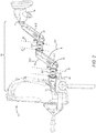
- FIG 2 is an enlarged view of the tool arm assembly 10 illustrated in Figure 1 .
- the intermediate link 18-1 has a rotation axis 24 and a rotation axis 26.
- the rotation axis 24 allows the intermediate link 18-1 to rotate with respect to the tool base link 16.
- the intermediate link 18-1 rotates in a generally horizontal plane.
- the rotation axis 26 allows the arm link 20-1 to rotate in the same generally horizontal plane with respect to the intermediate link 18-1.
- the arm link 20-1 can also rotate about a rotation axis 28 which is perpendicular to the rotation axis 24, and thereby move in directions 30-1, 30-2, which in this example are in a generally vertical plane.
- the intermediate link 18-2 has a rotation axis 32 about which the intermediate link may rotate with respect to the arm link 20-1, and a rotation axis 34 about which the intermediate link 18-2 may rotate with respect to the arm link 20-2.
- the arm link 20-2 is rotatable about a rotation axis 36 that is perpendicular to the rotation axis 34.
- FIG 3 is an enlarged view of the intermediate link 18-2.
- the intermediate link 18-2 includes a body 38-1 and the rotation axes 32, 34.
- a connector 40-1 is coupled to the body 38-1 and is at least partially rotatable about the rotation axis 32.
- the connector 40-1 is coupled to the arm link 20-1, but the connector 40-1 may be coupled to the tool base link 16.
- the connector 40-1 may be coupled to the arm link 20-1 or the tool base link 16 either via attachment mechanisms, such as bolts, screws, and the like, or may be coupled to the arm link 20-1 or the tool base link 16 by being integral with the arm link 20-1 or the tool base link 16, such as by being formed from the same material as that used to make all or a portion of the arm link 20-1 or the tool base link 16.
- the intermediate link 18-2 also includes a connector 40-2, which is coupled to the body 38-1 and is at least partially rotatable about the rotation axis 34.
- the connector 40-2 is coupled to the arm link 20-2.
- the intermediate link 18-2 includes a rotation lock mechanism 42-1 that is configured to selectively prevent rotation of the connector 40-1 about the rotation axis 32, and a rotation lock mechanism 42-2 that is configured to selectively prevent rotation of the first connector 40-2 about the rotation axis 34.
- the rotation lock mechanism 42-1 has an unlocked mode and a locked mode. In the unlocked mode, the connector 40-1 is at least partially rotatable about the rotation axis 32, and in the locked mode, the connecter 40-1 is fixed with respect to the body 38-1.
- the rotation lock mechanism 42-2 has an unlocked mode and a locked mode. In the unlocked mode, the connector 40-2 is at least partially rotatable about the rotation axis and 34, and in the locked mode, the connecter 40-2 is fixed with respect to the body 38-1.
- a user can thereby selectively activate the rotation mechanism 42-1 to prevent rotation of the intermediate link 18-2 with respect to the arm link 20-1 but allow rotation of the arm link 20-2 with respect to the intermediate link 18-2.
- the user can selectively activate the rotation mechanism 42-2 to prevent rotation of the intermediate link 18-2 with respect to the arm link 20-2 but allow rotation of the arm link 20-1 with respect to the intermediate link 18-2.
- the user may also selectively activate the rotation mechanism 42-1 to prevent rotation of the intermediate link 18-2 with respect to the arm link 20-1, and selectively activate the rotation mechanism 42-2 to prevent rotation of the intermediate link 18-2 with respect to the arm link 20-2.
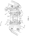
- Figure 4 is a cross-sectional view of the intermediate link 18-2 illustrated in Figure 3 .
- a shaft 44-1 is collinear with the rotation axis 32.
- the shaft 44-1 is fixed with respect to the connector 40-1 and rotatable with respect to the body 38-1, such that the shaft 44-1 rotates about the rotation axis 32 in conjunction with the connector 40-1 rotating about the rotation axis 32.
- the shaft 44-1 may be fixed with respect to the connector 40-1 via a keyed, i.e., non-circular, cross-sectional area 48 of the shaft 44-1 that matches a non-circular opening in the connector 40-1.
- the shaft 44-1 includes a lock interface area 50-1 that comprises a flat surface 52.
- the body 38-1 forms a threaded bore 54 that is substantially perpendicular with respect to the rotation axis 32, and has a longitudinal axis 56 that intersects the rotation axis 32.
- a threaded pin 58 engages the threaded bore 54.
- a handle 60 is attached to the pin 58, and the pin 58 may thereby be rotated in a clockwise direction such that the pin 58 engages the flat surface 52 in a locked position to prevent rotation of the shaft 44-1 and the connector 40-1.
- the handle 60 may be rotated in a counter-clockwise position to disengage the pin 58 from the lock interface area 50-1 to put the pin 58 in an unlocked position.
- the body 38-1 also includes a shaft 44-2 that is collinear with the rotation axis 34.
- the shaft 44-2 is fixed with respect to the connector 40-2 and rotatable with respect to the body 38-1, such that the shaft 44-2 rotates about the rotation axis 34 in conjunction with the connector 40-2 rotating about the rotation axis 34.
- the shaft 44-2 may be fixed with respect to the connector 40-2 via a keyed, i.e., non-circular, cross-sectional area 62 of the shaft 44-2 that matches a non-circular opening in the connector 40-2.
- the shaft 44-2 includes a lock interface area 50-2 that comprises a flat surface 64.
- the body 38-1 forms a threaded bore 66 that is substantially perpendicular with respect to the rotation axis 34 and has a longitudinal axis 68 that intersects the rotation axis 34.
- a threaded pin 70 engages the threaded bore 66.
- a handle 72 is attached to the pin 70, and the pin 70 may thereby be rotated in a clockwise direction such that the pin 70 engages the flat surface 64 in a locked position to prevent rotation of the shaft 44-2 and the connector 40-2.
- the handle 72 may be rotated in a counter clockwise position to disengage the pin 70 from the lock interface area 50-2 to put the pin 70 in an unlocked position.
- FIG. 5 is a cross-sectional view of an intermediate link 18-2A useful for understanding the invention.
- the intermediate link 18-2A is identical to the intermediate link 18-2 illustrated in Figures 3 and 4 , except that the lock interface areas 50-1, 50-2 comprise openings 74-1, 74-2 formed in shafts 44-1A, 44-2A, respectively.
- the pins 58, 70 may be rotated to extend into the respective openings 74-1, 74-2 to prevent rotation of the shafts 44-1A, 44-2A.
- FIG. 6 is an illustration of an intermediate link 18-3 according to an embodiment.
- the intermediate link 18-3 is substantially similar to the intermediate links 18-2, 18-2A discussed above except as otherwise discussed herein.
- the intermediate link 18-3 has a body 38-2 which forms pin through holes 76-1 - 76-4.
- a pin 78-1 is slidably coupled to the body 38-2 and is configured to slide along a pin axis 80-1.
- a connector 82-1 is coupled to the body 38-2 and is at least partially rotatable about the rotation axis 32.
- a connector 82-2 is coupled to the body 38-2 and is at least partially rotatable about the rotation axis 34.
- the connector 82-1 includes a bracket 84-1 that forms one or more openings 86.
- the connector 82-1 may be rotated about the axis 32 such that the openings 86 successively intersect the pin axis 80-1 at different rotation orientations of the connector 82-1 with respect to the body 38-2.
- the pin 78-1 is configured to engage an opening 86 to prevent rotation of the first connector 82-1 with respect to the body 38-2.
- the pin 78-1 has a head section 88 that includes a throat 90.
- a pin end 92 engages one of two holes 94-1, 94-2 to place the pin 78-1 in a locked mode or an unlocked mode.
- the hole 94-1 is sufficiently deep to allow the pin shaft of the pin 78-1 to extend through the body 38-2 and through the opening 86 in the bracket 84-1.
- the hole 94-2 is a shallow hole, and thus if the pin end 92 is placed in the hole 94-2, the shaft of the pin 78-1 cannot engage the opening 86, and the connector 82-1 can rotate with respect to the body 38-2.
- a pin 78-2 operates with respect to a bracket 84-2 of the connector 82-2 identically to that described above with regard to the pin 78-1 and the bracket 84-1 to selectively allow rotation of the connector 82-2 with respect to the body 38-2, or to prevent rotation of the connector 82-2 with respect to the body 38-2.
- Figure 7 is a cross-sectional view of the intermediate link 18-3 illustrated in Figure 6 .
- the body 38-2 forms two chambers 96-1, 96-2 in which springs 98-1, 98-2 are located, respectively.
- the pin 78-1 includes a collar 100-1 against which the spring 96-1 exerts a force to urge the pin 78-1 in a direction toward the bracket 84-1.
- the pin 78-2 includes a collar 100-2 against which the spring 96-2 exerts a force to urge the pin 78-2 in a direction toward the bracket 84-2.
Landscapes
- Engineering & Computer Science (AREA)
- General Engineering & Computer Science (AREA)
- Mechanical Engineering (AREA)
- Pivots And Pivotal Connections (AREA)
Description
- The embodiments relate generally to a locking intermediate link for a tool arm assembly.
- A tool arm assembly interfaces with and supports a tool to allow a human to easily manipulate the tool. A tool arm assembly may be coupled to a number of different systems, such as, for example, an exoskeleton, a stationary fixture such as a wall, or a mobile device such as a cart. A tool arm assembly typically includes one or more arm links that can move in a plane, such as a vertical plane, and intermediate links that couple the arm links and allow movement in another plane, such as a horizontal plane. With the flexibility provided by the multiple types of movement, a user may position the tool at precise locations.
- An intermediate link allows arm links to rotate about an axis of rotation of the intermediate link. While this is useful for tool positioning, unintentional rotation of an arm link can occur when a user removes his hands from the tool, leading to safety issues and other problems as the tool moves in an unintended manner.
KR20140026718
US2009/0072108 discloses a fan system including a fan, a bracket configured to mount to a ceiling structure, and a mounting assembly coupling the fan with the bracket. The mounting assembly comprises a fan mounting assembly secured to the fan; and a bracket mounting assembly secured to the bracket. The mounting assembly includes an elongate member extending between the fan mounting assembly and the bracket mounting assembly. The fan mounting assembly is configured to permit adjustment of the orientation of the fan axis about two axes that are perpendicular to the fan axis. The bracket mounting assembly is configured to permit adjustment of the orientation of the elongate member axis about two axes that are perpendicular to the elongate member axis. - According to the present invention, there is provided an intermediate link for a tool arm assembly according to
claim 1. Among other features, the embodiments allow a user of a tool arm assembly to selectively prevent rotation of arm links, or other links, and thereby ensure a tool does not unintentionally move if the user takes his hands off the tool. - In one embodiment, the intermediate link comprises a second rotation lock mechanism that is configured to selectively prevent rotation of the second connector about the second rotation axis.
- In one embodiment, the intermediate link includes a first shaft that is co-linear with the first rotation axis. The first shaft is fixed with respect to the first connector and rotatable with respect to the body. The first shaft comprises a lock interface area. The first rotation lock mechanism comprises a pin having a locked position and an unlocked position. In the locked position, the pin is engaged with the lock interface area to prevent rotation of the first shaft.
- In one embodiment, the first shaft forms an opening, and the lock interface area comprises the opening. In the locked position, at least a portion of the pin extends into the opening.
- In one embodiment, the body forms a threaded bore that is substantially perpendicular with respect to the first rotation axis. The threaded bore includes a longitudinal axis that intersects the first rotation axis. The pin includes threads that are configured to engage the threaded bore. A handle is attached to the pin. The pin extends substantially perpendicular with respect to the first rotation axis and is configured to contact the first shaft upon rotation of the pin.
- In one embodiment, the first shaft comprises a flat surface and the lock interface area comprises the flat surface. The pin is configured to contact the flat surface.
- In one embodiment, the first rotation lock mechanism has a first unlocked mode and a first locked mode. In the first unlocked mode, the first connector is at least partially rotatable about the first rotation axis, and in the first locked mode, the first connecter is fixed with respect to the body.
- In one embodiment, the bracket forms a plurality of openings. Each opening intersects the first pin axis at corresponding rotation orientations of the first connector with respect to the body.
- In another aspect, a tool arm assembly according to claim 8 is provided.
- In another embodiment, a tool arm assembly is provided that includes a tool interface link, a first arm link, a first intermediate link, a second arm link, and a second intermediate link.
- Those skilled in the art will appreciate the scope of the disclosure and realize additional aspects thereof after reading the following detailed description of the embodiments in association with the accompanying drawing figures.
- The accompanying drawing figures incorporated in and forming a part of this specification illustrate several aspects of the disclosure and, together with the description, serve to explain the principles of the disclosure.
-
Figure 1 is an illustration of a tool arm assembly useful for understanding the invention; -
Figure 2 is an enlarged view of the tool arm assembly illustrated inFigure 1 ; -
Figure 3 is an enlarged view of the intermediate link illustrated inFigure 2 ; -
Figure 4 is a cross-sectional view of the intermediate link illustrated inFigure 3 ; -
Figure 5 is a cross-sectional view of another intermediate link useful for understanding the invention; -
Figure 6 is an illustration of an intermediate link according to an embodiment; and -
Figure 7 is a cross-sectional view of the intermediate link illustrated inFigure 6 . - The embodiments set forth below represent the information to enable those skilled in the art to practice the embodiments and illustrate the best mode of practicing the embodiments. Upon reading the following description in light of the accompanying drawing figures, those skilled in the art will understand the concepts of the disclosure and will recognize applications of these concepts not particularly addressed herein. It should be understood that these concepts and applications fall within the scope of the disclosure and the accompanying claims.
- The use herein of ordinals in conjunction with an element is solely for distinguishing what might otherwise be similar or identical labels, such as "first connector" and "second connector," and does not imply a priority, a type, an importance, or other attribute, unless otherwise stated herein. The term "about" used herein in conjunction with a numeric value means any value that is within a range of ten percent greater than or ten percent less than the numeric value.
- The embodiments relate to an intermediate link for a tool arm assembly that includes first and second connectors that are at least partially rotatable about respective first and second rotation axes. The intermediate link includes first and second lock rotation mechanisms that are configured to selectively prevent rotation of the first and second connectors. Among other features, the embodiments allow a user of a tool arm assembly to selectively prevent rotation of arm links, or other links, and thereby ensure a tool does not unintentionally move if the user takes his hands off the tool.
-
Figure 1 is an illustration of atool arm assembly 10 useful for understanding the invention. In this example, thetool arm assembly 10 is coupled to anexoskeleton 12; however, the embodiments are not limited to a tool arm assembly that is coupled to an exoskeleton and have applicability in any application that utilizes a tool arm assembly. For example, the tool arm assembly may be coupled to a stationary surface, such as a wall, a ceiling, a floor, or a bench, or to a mobile surface, such as a cart. - The
tool arm assembly 10 can be coupled to atool 14, and facilitates controlled and safe movement of thetool 14 by a user (not illustrated). Thetool arm assembly 10 in this example includes atool base link 16 that facilitates coupling of thetool arm assembly 10 to theexoskeleton 12. Thetool base link 16 is coupled to an intermediate link 18-1, which in turn is coupled to an arm link 20-1. The arm link 20-1 is coupled to an intermediate link 18-2, which is coupled to an arm link 20-2. The intermediate links 18-1, 18-2 may be referred to generally herein as intermediate links 18. The arm links 20-1, 20-2 may be referred to generally herein as arm links 20. The arm link 20-2 includes atool attachment interface 22 that facilitates coupling of thetool 14 to thetool arm assembly 10. While for purposes of illustration only two intermediate links 18 and two arm links 20 are shown, thetool arm assembly 10 may comprise any number of intermediate links 18 and arm links 20. -
Figure 2 is an enlarged view of thetool arm assembly 10 illustrated inFigure 1 . The intermediate link 18-1 has arotation axis 24 and arotation axis 26. Therotation axis 24 allows the intermediate link 18-1 to rotate with respect to thetool base link 16. In this example, the intermediate link 18-1 rotates in a generally horizontal plane. Therotation axis 26 allows the arm link 20-1 to rotate in the same generally horizontal plane with respect to the intermediate link 18-1. The arm link 20-1 can also rotate about arotation axis 28 which is perpendicular to therotation axis 24, and thereby move in directions 30-1, 30-2, which in this example are in a generally vertical plane. - The intermediate link 18-2 has a
rotation axis 32 about which the intermediate link may rotate with respect to the arm link 20-1, and arotation axis 34 about which the intermediate link 18-2 may rotate with respect to the arm link 20-2. The arm link 20-2 is rotatable about arotation axis 36 that is perpendicular to therotation axis 34. -
Figure 3 is an enlarged view of the intermediate link 18-2. The intermediate link 18-2 includes a body 38-1 and the rotation axes 32, 34. A connector 40-1 is coupled to the body 38-1 and is at least partially rotatable about therotation axis 32. In this example, the connector 40-1 is coupled to the arm link 20-1, but the connector 40-1 may be coupled to thetool base link 16. The connector 40-1 may be coupled to the arm link 20-1 or thetool base link 16 either via attachment mechanisms, such as bolts, screws, and the like, or may be coupled to the arm link 20-1 or thetool base link 16 by being integral with the arm link 20-1 or thetool base link 16, such as by being formed from the same material as that used to make all or a portion of the arm link 20-1 or thetool base link 16. - The intermediate link 18-2 also includes a connector 40-2, which is coupled to the body 38-1 and is at least partially rotatable about the
rotation axis 34. In this example, the connector 40-2 is coupled to the arm link 20-2. - The intermediate link 18-2 includes a rotation lock mechanism 42-1 that is configured to selectively prevent rotation of the connector 40-1 about the
rotation axis 32, and a rotation lock mechanism 42-2 that is configured to selectively prevent rotation of the first connector 40-2 about therotation axis 34. The rotation lock mechanism 42-1 has an unlocked mode and a locked mode. In the unlocked mode, the connector 40-1 is at least partially rotatable about therotation axis 32, and in the locked mode, the connecter 40-1 is fixed with respect to the body 38-1. Similarly, the rotation lock mechanism 42-2 has an unlocked mode and a locked mode. In the unlocked mode, the connector 40-2 is at least partially rotatable about the rotation axis and 34, and in the locked mode, the connecter 40-2 is fixed with respect to the body 38-1. - A user can thereby selectively activate the rotation mechanism 42-1 to prevent rotation of the intermediate link 18-2 with respect to the arm link 20-1 but allow rotation of the arm link 20-2 with respect to the intermediate link 18-2. Alternatively, the user can selectively activate the rotation mechanism 42-2 to prevent rotation of the intermediate link 18-2 with respect to the arm link 20-2 but allow rotation of the arm link 20-1 with respect to the intermediate link 18-2. The user may also selectively activate the rotation mechanism 42-1 to prevent rotation of the intermediate link 18-2 with respect to the arm link 20-1, and selectively activate the rotation mechanism 42-2 to prevent rotation of the intermediate link 18-2 with respect to the arm link 20-2.
-
Figure 4 is a cross-sectional view of the intermediate link 18-2 illustrated inFigure 3 . A shaft 44-1 is collinear with therotation axis 32. The shaft 44-1 is fixed with respect to the connector 40-1 and rotatable with respect to the body 38-1, such that the shaft 44-1 rotates about therotation axis 32 in conjunction with the connector 40-1 rotating about therotation axis 32. The shaft 44-1 may be fixed with respect to the connector 40-1 via a keyed, i.e., non-circular,cross-sectional area 48 of the shaft 44-1 that matches a non-circular opening in the connector 40-1. The shaft 44-1 includes a lock interface area 50-1 that comprises aflat surface 52. The body 38-1 forms a threadedbore 54 that is substantially perpendicular with respect to therotation axis 32, and has alongitudinal axis 56 that intersects therotation axis 32. A threadedpin 58 engages the threaded bore 54. Ahandle 60 is attached to thepin 58, and thepin 58 may thereby be rotated in a clockwise direction such that thepin 58 engages theflat surface 52 in a locked position to prevent rotation of the shaft 44-1 and the connector 40-1. Thehandle 60 may be rotated in a counter-clockwise position to disengage thepin 58 from the lock interface area 50-1 to put thepin 58 in an unlocked position. - The body 38-1 also includes a shaft 44-2 that is collinear with the
rotation axis 34. The shaft 44-2 is fixed with respect to the connector 40-2 and rotatable with respect to the body 38-1, such that the shaft 44-2 rotates about therotation axis 34 in conjunction with the connector 40-2 rotating about therotation axis 34. As discussed above, the shaft 44-2 may be fixed with respect to the connector 40-2 via a keyed, i.e., non-circular,cross-sectional area 62 of the shaft 44-2 that matches a non-circular opening in the connector 40-2. The shaft 44-2 includes a lock interface area 50-2 that comprises aflat surface 64. The body 38-1 forms a threadedbore 66 that is substantially perpendicular with respect to therotation axis 34 and has alongitudinal axis 68 that intersects therotation axis 34. A threadedpin 70 engages the threaded bore 66. Ahandle 72 is attached to thepin 70, and thepin 70 may thereby be rotated in a clockwise direction such that thepin 70 engages theflat surface 64 in a locked position to prevent rotation of the shaft 44-2 and the connector 40-2. Thehandle 72 may be rotated in a counter clockwise position to disengage thepin 70 from the lock interface area 50-2 to put thepin 70 in an unlocked position. -
Figure 5 is a cross-sectional view of an intermediate link 18-2A useful for understanding the invention. The intermediate link 18-2A is identical to the intermediate link 18-2 illustrated inFigures 3 and4 , except that the lock interface areas 50-1, 50-2 comprise openings 74-1, 74-2 formed in shafts 44-1A, 44-2A, respectively. Thepins -
Figure 6 is an illustration of an intermediate link 18-3 according to an embodiment. The intermediate link 18-3 is substantially similar to the intermediate links 18-2, 18-2A discussed above except as otherwise discussed herein. The intermediate link 18-3 has a body 38-2 which forms pin through holes 76-1 - 76-4. A pin 78-1 is slidably coupled to the body 38-2 and is configured to slide along a pin axis 80-1. A connector 82-1 is coupled to the body 38-2 and is at least partially rotatable about therotation axis 32. A connector 82-2 is coupled to the body 38-2 and is at least partially rotatable about therotation axis 34. - The connector 82-1 includes a bracket 84-1 that forms one or
more openings 86. The connector 82-1 may be rotated about theaxis 32 such that theopenings 86 successively intersect the pin axis 80-1 at different rotation orientations of the connector 82-1 with respect to the body 38-2. The pin 78-1 is configured to engage anopening 86 to prevent rotation of the first connector 82-1 with respect to the body 38-2. - The pin 78-1 has a
head section 88 that includes athroat 90. Apin end 92 engages one of two holes 94-1, 94-2 to place the pin 78-1 in a locked mode or an unlocked mode. The hole 94-1 is sufficiently deep to allow the pin shaft of the pin 78-1 to extend through the body 38-2 and through theopening 86 in the bracket 84-1. The hole 94-2 is a shallow hole, and thus if thepin end 92 is placed in the hole 94-2, the shaft of the pin 78-1 cannot engage theopening 86, and the connector 82-1 can rotate with respect to the body 38-2. A pin 78-2 operates with respect to a bracket 84-2 of the connector 82-2 identically to that described above with regard to the pin 78-1 and the bracket 84-1 to selectively allow rotation of the connector 82-2 with respect to the body 38-2, or to prevent rotation of the connector 82-2 with respect to the body 38-2. -
Figure 7 is a cross-sectional view of the intermediate link 18-3 illustrated inFigure 6 . The body 38-2 forms two chambers 96-1, 96-2 in which springs 98-1, 98-2 are located, respectively. The pin 78-1 includes a collar 100-1 against which the spring 96-1 exerts a force to urge the pin 78-1 in a direction toward the bracket 84-1. Similarly, the pin 78-2 includes a collar 100-2 against which the spring 96-2 exerts a force to urge the pin 78-2 in a direction toward the bracket 84-2. - Those skilled in the art will recognize improvements and modifications to the preferred embodiments of the disclosure. All such improvements and modifications are considered within the scope of the concepts disclosed herein and the claims that follow.
Claims (12)
- An intermediate link (18-3) for a tool arm assembly comprising:a body (38-2) having a first rotation axis (32) and a second rotation axis (34), the body forming a through hole (76-1) that extends from a top surface of the body to a bottom surface of the body;a first connector (82-1) coupled to the body, the first connector being at least partially rotatable about the first rotation axis;a second connector (82-2) coupled to the body, the second connector being at least partially rotatable about the second rotation axis; anda first rotation lock mechanism comprising a first pin (78-1) that is slidably coupled to the body and is positioned in the through hole, the first pin slidable along a first pin axis, the first pin having a length greater than a height of the body defined by a distance between the top surface and the bottom surface;wherein the first connector further comprises a first bracket (84-1) forming at least one opening (86) that intersects the first pin axis at a particular rotation orientation of the first connector with respect to the body;the first pin is configured to engage the at least one opening of the first bracket to prevent rotation of the first connector with respect to the body; andthe first pin comprises a first end (92) having a curved head section (88) and a second end that is straight, the body forms a first hole (94-1) in the top surface having a first depth sufficient to allow a portion of the curved head section to be positioned in the hole and the second end to engage the at least one opening of the first bracket.
- The intermediate link of claim 1, further comprising a second rotation lock mechanism configured to selectively prevent rotation of the second connector about the second rotation axis.
- The intermediate link of claim 2, wherein the first rotation lock mechanism has a first unlocked mode and a first locked mode, in the first unlocked mode the first connector being at least partially rotatable about the first rotation axis and in the first locked mode the first connector being fixed with respect to the body, and wherein the second rotation lock mechanism has a second unlocked mode and a second locked mode, in the second unlocked mode the second connector being at least partially rotatable about the second rotation axis and in the second locked mode the second connecter being fixed with respect to the body.
- The intermediate link of claim 1, wherein the first bracket forms a plurality of openings, including the at least one opening, each opening of the plurality of openings intersecting the first pin axis at corresponding rotation orientations of the first connector with respect to the body.
- The intermediate link of claim 1, further comprising:a second rotation lock mechanism configured to selectively prevent rotation of the second connector about the second rotation axis, wherein the second rotation lock mechanism comprises a second pin (78-2) that is slidably coupled to the body and is configured to slide along a second pin axis;the second connector comprises a second bracket (84-2) forming at least one opening that intersects the second pin axis at a particular rotation orientation of the second connector with respect to the body; andthe second pin is configured to engage the at least one opening of the second bracket to prevent rotation of the second connector with respect to the body.
- The intermediate link of claim 1 wherein the body forms a second hole (94-2) in the top surface having a second depth that is a shallower depth than the first depth that allows a portion of the curved head section to be positioned in the hole and prevents the second end from engaging the at least one opening of the first bracket.
- The intermediate link of claim 1 further comprising a collar (100-1) fixed to the first pin, and further comprising a spring (96-1) configured to exert a force on the collar to urge the second end in a direction toward the first bracket.
- A tool arm assembly comprising:a first arm link (20-1);a second arm link (20-2); andan intermediate link according to claim 1;wherein the first connector is further coupled to the first arm link; andwherein the second connector is further coupled to the second arm link.
- The tool arm assembly of claim 8, wherein the first arm link is configured to rotate about a first arm rotation axis that is perpendicular to the first rotation axis.
- The tool arm assembly of claim 9, wherein the second arm link is configured to rotate about a second arm rotation axis that is perpendicular to the second rotation axis.
- A tool arm assembly comprising:a tool interface link;a first arm link;a first intermediate link according to claim 1;wherein the first connector is further coupled to the tool interface link; andwherein second connector is further coupled to the first arm link;a second arm link;a second intermediate link comprising:a second body having a third rotation axis and a fourth rotation axis;a third connector coupled to the second body and the first arm link, the third connector being at least partially rotatable about the third rotation axis;a fourth connector coupled to the second body and to the second arm link, the fourth connector being at least partially rotatable about the fourth rotation axis; andat least one of:a third rotation lock mechanism configured to selectively prevent rotation of the third connector about the third rotation axis; anda fourth rotation lock mechanism configured to selectively prevent rotation of the fourth connector about the fourth rotation axis.
- The tool arm assembly of claim 11, wherein the second arm link (20-2) further comprises a tool attachment interface (22) configured to interface with a tool (14).
Applications Claiming Priority (2)
| Application Number | Priority Date | Filing Date | Title |
|---|---|---|---|
| US14/843,344 US9802307B2 (en) | 2015-09-02 | 2015-09-02 | Locking intermediate link for a tool arm assembly |
| PCT/US2016/049961 WO2017040827A1 (en) | 2015-09-02 | 2016-09-01 | Locking intermediate link for a tool arm assembly |
Publications (3)
| Publication Number | Publication Date |
|---|---|
| EP3344421A1 EP3344421A1 (en) | 2018-07-11 |
| EP3344421A4 EP3344421A4 (en) | 2019-05-01 |
| EP3344421B1 true EP3344421B1 (en) | 2021-08-18 |
Family
ID=58103568
Family Applications (1)
| Application Number | Title | Priority Date | Filing Date |
|---|---|---|---|
| EP16843004.9A Active EP3344421B1 (en) | 2015-09-02 | 2016-09-01 | Locking intermediate link for a tool arm assembly |
Country Status (6)
| Country | Link |
|---|---|
| US (1) | US9802307B2 (en) |
| EP (1) | EP3344421B1 (en) |
| JP (1) | JP6789285B2 (en) |
| AU (1) | AU2016317948B2 (en) |
| CA (1) | CA2996440C (en) |
| WO (1) | WO2017040827A1 (en) |
Families Citing this family (3)
| Publication number | Priority date | Publication date | Assignee | Title |
|---|---|---|---|---|
| CN109483464B (en) * | 2018-11-14 | 2021-03-30 | 安徽蓝德自动化科技有限公司 | Industrial instrument panel assembly table and assembly method thereof |
| CN110788838B (en) * | 2019-11-29 | 2025-10-03 | 慈溪市东鑫镁业有限公司 | A power-assisted lifting mechanical arm device |
| US20210402538A1 (en) * | 2020-06-30 | 2021-12-30 | Gulfstream Aerospace Corporation | Apparatus and method for holding and/or using a tool |
Citations (1)
| Publication number | Priority date | Publication date | Assignee | Title |
|---|---|---|---|---|
| US20090072108A1 (en) * | 2007-09-17 | 2009-03-19 | Delta T Corporation | Ceiling Fan with Angled Mounting |
Family Cites Families (22)
| Publication number | Priority date | Publication date | Assignee | Title |
|---|---|---|---|---|
| US4017168A (en) | 1974-09-16 | 1977-04-12 | Brown Garrett W | Equipment for use with hand held motion picture cameras |
| US4394075A (en) | 1976-06-28 | 1983-07-19 | Garrett Brown | Support apparatus |
| CH643329A5 (en) * | 1979-09-11 | 1984-05-30 | Willi Markus | JOINT. |
| JPS6284537U (en) * | 1985-11-18 | 1987-05-29 | ||
| US4838135A (en) | 1986-07-31 | 1989-06-13 | Hevoyan Varoujan H | Work transport for machine tools |
| JPH08281577A (en) | 1995-04-13 | 1996-10-29 | Nippondenso Co Ltd | Cylindrical coordinate robot rotation drive structure |
| JP2868734B2 (en) * | 1996-07-29 | 1999-03-10 | タキゲン製造株式会社 | Folding table support device |
| US5881984A (en) * | 1997-06-20 | 1999-03-16 | Lin; Chin-Chih | Dimensional adjusting device for computer keyboards racks |
| US6030130A (en) * | 1997-07-07 | 2000-02-29 | George Paddock Ii, Inc. | Body mounted camera support system |
| US7055789B2 (en) | 2002-05-14 | 2006-06-06 | Automation Tool Company | Articulating tool arm with positional feedback |
| CN2838881Y (en) | 2005-10-12 | 2006-11-22 | 贸巨企业股份有限公司 | Operating arm |
| US7338022B2 (en) * | 2006-08-04 | 2008-03-04 | Chin-Jui Hung | Support apparatus for suspending a monitor |
| US7510155B2 (en) * | 2007-07-02 | 2009-03-31 | Shian-Nung Huang | Single spring supporting device |
| US20090095874A1 (en) * | 2007-10-12 | 2009-04-16 | Phillip Young | Cantilevered releasable locking mechanism |
| CN101471144B (en) * | 2007-12-28 | 2013-06-05 | 鸿富锦精密工业(深圳)有限公司 | Regulating mechanism for display equipment |
| CN101684882B (en) * | 2008-09-25 | 2012-07-18 | 鸿富锦精密工业(深圳)有限公司 | Elevator mechanism |
| WO2010039707A1 (en) * | 2008-09-30 | 2010-04-08 | Brown Garrett W | Biased hinge for equipoising support equipment |
| CN101713487B (en) * | 2008-10-08 | 2013-06-05 | 鸿富锦精密工业(深圳)有限公司 | Lifting mechanism |
| CN101858482B (en) * | 2009-04-13 | 2013-07-03 | 鸿富锦精密工业(深圳)有限公司 | Supporting mechanism |
| US8763267B2 (en) * | 2012-01-20 | 2014-07-01 | Hexagon Technology Center Gmbh | Locking counterbalance for a CMM |
| KR20140026718A (en) | 2012-08-23 | 2014-03-06 | 대우조선해양 주식회사 | Device for fixing hinge of multi link arm |
| US9423066B2 (en) * | 2014-03-27 | 2016-08-23 | Hiwin Technologies Corp. | Support arm with a multiple degree of freedom locking device |
-
2015
- 2015-09-02 US US14/843,344 patent/US9802307B2/en active Active - Reinstated
-
2016
- 2016-09-01 CA CA2996440A patent/CA2996440C/en active Active
- 2016-09-01 WO PCT/US2016/049961 patent/WO2017040827A1/en not_active Ceased
- 2016-09-01 AU AU2016317948A patent/AU2016317948B2/en not_active Ceased
- 2016-09-01 EP EP16843004.9A patent/EP3344421B1/en active Active
- 2016-09-01 JP JP2018511490A patent/JP6789285B2/en not_active Expired - Fee Related
Patent Citations (1)
| Publication number | Priority date | Publication date | Assignee | Title |
|---|---|---|---|---|
| US20090072108A1 (en) * | 2007-09-17 | 2009-03-19 | Delta T Corporation | Ceiling Fan with Angled Mounting |
Also Published As
| Publication number | Publication date |
|---|---|
| AU2016317948A1 (en) | 2018-03-08 |
| JP6789285B2 (en) | 2020-11-25 |
| JP2018535363A (en) | 2018-11-29 |
| EP3344421A4 (en) | 2019-05-01 |
| WO2017040827A1 (en) | 2017-03-09 |
| US20170057077A1 (en) | 2017-03-02 |
| AU2016317948B2 (en) | 2021-08-12 |
| CA2996440C (en) | 2021-12-21 |
| CA2996440A1 (en) | 2017-03-09 |
| EP3344421A1 (en) | 2018-07-11 |
| US9802307B2 (en) | 2017-10-31 |
Similar Documents
| Publication | Publication Date | Title |
|---|---|---|
| US9713275B2 (en) | Lock catch structure | |
| US11085487B2 (en) | Positioning locking mechanism of rotational member | |
| US9091293B1 (en) | Rotary fastener | |
| US10760611B2 (en) | Rotatable connection having rotational angle limitation | |
| CA2996440C (en) | Locking intermediate link for a tool arm assembly | |
| US20140262610A1 (en) | Systems for Assisted Braking Belay with a Lever Disengagement Mechanism | |
| CN202125709U (en) | Television base with rotating and locking functions | |
| CN107489325B (en) | Rotating lock system | |
| EP3278745A3 (en) | Adapter assemblies for surgical devices | |
| TW202108316A (en) | Torsion structure enabling a plurality of first locking members to be evenly distributed with all rotational force to have longer service life | |
| TW201404995A (en) | Handle-actuated sliding door lock actuation assemblies | |
| EP3050450B1 (en) | Locking clip and anchor assembly for a tether | |
| EP2963208B1 (en) | Lock for portable generators | |
| CN113349871B (en) | Angle-adjustable clamp applying forceps with clamping head | |
| CN109834726A (en) | Electronic grasping device | |
| US20180028384A1 (en) | Quarter turn track bracket (QTTB) for patient lifter ceiling track mechanism and methods thereof | |
| KR20260051368A (en) | Load-bearing unit | |
| US20250058433A1 (en) | Hydraulic torque wrench | |
| US20160126026A1 (en) | Switch extension device and mounting assembly | |
| CN115844536B (en) | robotic arm components and surgical robots | |
| CN110562440A (en) | A three-degree-of-freedom pilot control device | |
| CN210890735U (en) | A real-time network engineering monitoring and alarm device that is easy to fix | |
| JP6147150B2 (en) | Emergency unlocking mechanism, locking device, hinged door device, and private room unit | |
| US20080265596A1 (en) | Light Weight Lifting Tool for Subsea Equipment | |
| CN221865964U (en) | Surgical robot fast-assembling structure and robot system |
Legal Events
| Date | Code | Title | Description |
|---|---|---|---|
| STAA | Information on the status of an ep patent application or granted ep patent |
Free format text: STATUS: THE INTERNATIONAL PUBLICATION HAS BEEN MADE |
|
| PUAI | Public reference made under article 153(3) epc to a published international application that has entered the european phase |
Free format text: ORIGINAL CODE: 0009012 |
|
| STAA | Information on the status of an ep patent application or granted ep patent |
Free format text: STATUS: REQUEST FOR EXAMINATION WAS MADE |
|
| 17P | Request for examination filed |
Effective date: 20180307 |
|
| AK | Designated contracting states |
Kind code of ref document: A1 Designated state(s): AL AT BE BG CH CY CZ DE DK EE ES FI FR GB GR HR HU IE IS IT LI LT LU LV MC MK MT NL NO PL PT RO RS SE SI SK SM TR |
|
| AX | Request for extension of the european patent |
Extension state: BA ME |
|
| DAV | Request for validation of the european patent (deleted) | ||
| DAX | Request for extension of the european patent (deleted) | ||
| A4 | Supplementary search report drawn up and despatched |
Effective date: 20190328 |
|
| RIC1 | Information provided on ipc code assigned before grant |
Ipc: B25J 19/00 20060101ALI20190322BHEP Ipc: B25J 9/00 20060101AFI20190322BHEP Ipc: B25J 18/04 20060101ALI20190322BHEP |
|
| STAA | Information on the status of an ep patent application or granted ep patent |
Free format text: STATUS: EXAMINATION IS IN PROGRESS |
|
| 17Q | First examination report despatched |
Effective date: 20201014 |
|
| GRAP | Despatch of communication of intention to grant a patent |
Free format text: ORIGINAL CODE: EPIDOSNIGR1 |
|
| STAA | Information on the status of an ep patent application or granted ep patent |
Free format text: STATUS: GRANT OF PATENT IS INTENDED |
|
| INTG | Intention to grant announced |
Effective date: 20210426 |
|
| GRAS | Grant fee paid |
Free format text: ORIGINAL CODE: EPIDOSNIGR3 |
|
| GRAA | (expected) grant |
Free format text: ORIGINAL CODE: 0009210 |
|
| STAA | Information on the status of an ep patent application or granted ep patent |
Free format text: STATUS: THE PATENT HAS BEEN GRANTED |
|
| AK | Designated contracting states |
Kind code of ref document: B1 Designated state(s): AL AT BE BG CH CY CZ DE DK EE ES FI FR GB GR HR HU IE IS IT LI LT LU LV MC MK MT NL NO PL PT RO RS SE SI SK SM TR |
|
| REG | Reference to a national code |
Ref country code: GB Ref legal event code: FG4D |
|
| REG | Reference to a national code |
Ref country code: CH Ref legal event code: EP |
|
| REG | Reference to a national code |
Ref country code: DE Ref legal event code: R096 Ref document number: 602016062502 Country of ref document: DE |
|
| REG | Reference to a national code |
Ref country code: IE Ref legal event code: FG4D Ref country code: AT Ref legal event code: REF Ref document number: 1421201 Country of ref document: AT Kind code of ref document: T Effective date: 20210915 |
|
| REG | Reference to a national code |
Ref country code: LT Ref legal event code: MG9D |
|
| REG | Reference to a national code |
Ref country code: NL Ref legal event code: MP Effective date: 20210818 |
|
| REG | Reference to a national code |
Ref country code: AT Ref legal event code: MK05 Ref document number: 1421201 Country of ref document: AT Kind code of ref document: T Effective date: 20210818 |
|
| PG25 | Lapsed in a contracting state [announced via postgrant information from national office to epo] |
Ref country code: RS Free format text: LAPSE BECAUSE OF FAILURE TO SUBMIT A TRANSLATION OF THE DESCRIPTION OR TO PAY THE FEE WITHIN THE PRESCRIBED TIME-LIMIT Effective date: 20210818 Ref country code: SE Free format text: LAPSE BECAUSE OF FAILURE TO SUBMIT A TRANSLATION OF THE DESCRIPTION OR TO PAY THE FEE WITHIN THE PRESCRIBED TIME-LIMIT Effective date: 20210818 Ref country code: LT Free format text: LAPSE BECAUSE OF FAILURE TO SUBMIT A TRANSLATION OF THE DESCRIPTION OR TO PAY THE FEE WITHIN THE PRESCRIBED TIME-LIMIT Effective date: 20210818 Ref country code: BG Free format text: LAPSE BECAUSE OF FAILURE TO SUBMIT A TRANSLATION OF THE DESCRIPTION OR TO PAY THE FEE WITHIN THE PRESCRIBED TIME-LIMIT Effective date: 20211118 Ref country code: AT Free format text: LAPSE BECAUSE OF FAILURE TO SUBMIT A TRANSLATION OF THE DESCRIPTION OR TO PAY THE FEE WITHIN THE PRESCRIBED TIME-LIMIT Effective date: 20210818 Ref country code: NO Free format text: LAPSE BECAUSE OF FAILURE TO SUBMIT A TRANSLATION OF THE DESCRIPTION OR TO PAY THE FEE WITHIN THE PRESCRIBED TIME-LIMIT Effective date: 20211118 Ref country code: PT Free format text: LAPSE BECAUSE OF FAILURE TO SUBMIT A TRANSLATION OF THE DESCRIPTION OR TO PAY THE FEE WITHIN THE PRESCRIBED TIME-LIMIT Effective date: 20211220 Ref country code: HR Free format text: LAPSE BECAUSE OF FAILURE TO SUBMIT A TRANSLATION OF THE DESCRIPTION OR TO PAY THE FEE WITHIN THE PRESCRIBED TIME-LIMIT Effective date: 20210818 Ref country code: ES Free format text: LAPSE BECAUSE OF FAILURE TO SUBMIT A TRANSLATION OF THE DESCRIPTION OR TO PAY THE FEE WITHIN THE PRESCRIBED TIME-LIMIT Effective date: 20210818 Ref country code: FI Free format text: LAPSE BECAUSE OF FAILURE TO SUBMIT A TRANSLATION OF THE DESCRIPTION OR TO PAY THE FEE WITHIN THE PRESCRIBED TIME-LIMIT Effective date: 20210818 |
|
| PG25 | Lapsed in a contracting state [announced via postgrant information from national office to epo] |
Ref country code: PL Free format text: LAPSE BECAUSE OF FAILURE TO SUBMIT A TRANSLATION OF THE DESCRIPTION OR TO PAY THE FEE WITHIN THE PRESCRIBED TIME-LIMIT Effective date: 20210818 Ref country code: LV Free format text: LAPSE BECAUSE OF FAILURE TO SUBMIT A TRANSLATION OF THE DESCRIPTION OR TO PAY THE FEE WITHIN THE PRESCRIBED TIME-LIMIT Effective date: 20210818 Ref country code: GR Free format text: LAPSE BECAUSE OF FAILURE TO SUBMIT A TRANSLATION OF THE DESCRIPTION OR TO PAY THE FEE WITHIN THE PRESCRIBED TIME-LIMIT Effective date: 20211119 |
|
| PG25 | Lapsed in a contracting state [announced via postgrant information from national office to epo] |
Ref country code: NL Free format text: LAPSE BECAUSE OF FAILURE TO SUBMIT A TRANSLATION OF THE DESCRIPTION OR TO PAY THE FEE WITHIN THE PRESCRIBED TIME-LIMIT Effective date: 20210818 |
|
| PG25 | Lapsed in a contracting state [announced via postgrant information from national office to epo] |
Ref country code: DK Free format text: LAPSE BECAUSE OF FAILURE TO SUBMIT A TRANSLATION OF THE DESCRIPTION OR TO PAY THE FEE WITHIN THE PRESCRIBED TIME-LIMIT Effective date: 20210818 |
|
| REG | Reference to a national code |
Ref country code: CH Ref legal event code: PL |
|
| REG | Reference to a national code |
Ref country code: DE Ref legal event code: R097 Ref document number: 602016062502 Country of ref document: DE |
|
| REG | Reference to a national code |
Ref country code: BE Ref legal event code: MM Effective date: 20210930 |
|
| PG25 | Lapsed in a contracting state [announced via postgrant information from national office to epo] |
Ref country code: SM Free format text: LAPSE BECAUSE OF FAILURE TO SUBMIT A TRANSLATION OF THE DESCRIPTION OR TO PAY THE FEE WITHIN THE PRESCRIBED TIME-LIMIT Effective date: 20210818 Ref country code: SK Free format text: LAPSE BECAUSE OF FAILURE TO SUBMIT A TRANSLATION OF THE DESCRIPTION OR TO PAY THE FEE WITHIN THE PRESCRIBED TIME-LIMIT Effective date: 20210818 Ref country code: RO Free format text: LAPSE BECAUSE OF FAILURE TO SUBMIT A TRANSLATION OF THE DESCRIPTION OR TO PAY THE FEE WITHIN THE PRESCRIBED TIME-LIMIT Effective date: 20210818 Ref country code: MC Free format text: LAPSE BECAUSE OF FAILURE TO SUBMIT A TRANSLATION OF THE DESCRIPTION OR TO PAY THE FEE WITHIN THE PRESCRIBED TIME-LIMIT Effective date: 20210818 Ref country code: EE Free format text: LAPSE BECAUSE OF FAILURE TO SUBMIT A TRANSLATION OF THE DESCRIPTION OR TO PAY THE FEE WITHIN THE PRESCRIBED TIME-LIMIT Effective date: 20210818 Ref country code: CZ Free format text: LAPSE BECAUSE OF FAILURE TO SUBMIT A TRANSLATION OF THE DESCRIPTION OR TO PAY THE FEE WITHIN THE PRESCRIBED TIME-LIMIT Effective date: 20210818 Ref country code: AL Free format text: LAPSE BECAUSE OF FAILURE TO SUBMIT A TRANSLATION OF THE DESCRIPTION OR TO PAY THE FEE WITHIN THE PRESCRIBED TIME-LIMIT Effective date: 20210818 |
|
| PLBE | No opposition filed within time limit |
Free format text: ORIGINAL CODE: 0009261 |
|
| STAA | Information on the status of an ep patent application or granted ep patent |
Free format text: STATUS: NO OPPOSITION FILED WITHIN TIME LIMIT |
|
| 26N | No opposition filed |
Effective date: 20220519 |
|
| GBPC | Gb: european patent ceased through non-payment of renewal fee |
Effective date: 20211118 |
|
| PG25 | Lapsed in a contracting state [announced via postgrant information from national office to epo] |
Ref country code: LU Free format text: LAPSE BECAUSE OF NON-PAYMENT OF DUE FEES Effective date: 20210901 Ref country code: IT Free format text: LAPSE BECAUSE OF FAILURE TO SUBMIT A TRANSLATION OF THE DESCRIPTION OR TO PAY THE FEE WITHIN THE PRESCRIBED TIME-LIMIT Effective date: 20210818 Ref country code: IE Free format text: LAPSE BECAUSE OF NON-PAYMENT OF DUE FEES Effective date: 20210901 Ref country code: BE Free format text: LAPSE BECAUSE OF NON-PAYMENT OF DUE FEES Effective date: 20210930 |
|
| PG25 | Lapsed in a contracting state [announced via postgrant information from national office to epo] |
Ref country code: SI Free format text: LAPSE BECAUSE OF FAILURE TO SUBMIT A TRANSLATION OF THE DESCRIPTION OR TO PAY THE FEE WITHIN THE PRESCRIBED TIME-LIMIT Effective date: 20210818 Ref country code: LI Free format text: LAPSE BECAUSE OF NON-PAYMENT OF DUE FEES Effective date: 20210930 Ref country code: CH Free format text: LAPSE BECAUSE OF NON-PAYMENT OF DUE FEES Effective date: 20210930 |
|
| PG25 | Lapsed in a contracting state [announced via postgrant information from national office to epo] |
Ref country code: FR Free format text: LAPSE BECAUSE OF NON-PAYMENT OF DUE FEES Effective date: 20211018 |
|
| PG25 | Lapsed in a contracting state [announced via postgrant information from national office to epo] |
Ref country code: GB Free format text: LAPSE BECAUSE OF NON-PAYMENT OF DUE FEES Effective date: 20211118 |
|
| PGFP | Annual fee paid to national office [announced via postgrant information from national office to epo] |
Ref country code: TR Payment date: 20220822 Year of fee payment: 7 Ref country code: DE Payment date: 20220928 Year of fee payment: 7 |
|
| PG25 | Lapsed in a contracting state [announced via postgrant information from national office to epo] |
Ref country code: HU Free format text: LAPSE BECAUSE OF FAILURE TO SUBMIT A TRANSLATION OF THE DESCRIPTION OR TO PAY THE FEE WITHIN THE PRESCRIBED TIME-LIMIT; INVALID AB INITIO Effective date: 20160901 |
|
| PG25 | Lapsed in a contracting state [announced via postgrant information from national office to epo] |
Ref country code: CY Free format text: LAPSE BECAUSE OF FAILURE TO SUBMIT A TRANSLATION OF THE DESCRIPTION OR TO PAY THE FEE WITHIN THE PRESCRIBED TIME-LIMIT Effective date: 20210818 |
|
| REG | Reference to a national code |
Ref country code: DE Ref legal event code: R119 Ref document number: 602016062502 Country of ref document: DE |
|
| PG25 | Lapsed in a contracting state [announced via postgrant information from national office to epo] |
Ref country code: MK Free format text: LAPSE BECAUSE OF FAILURE TO SUBMIT A TRANSLATION OF THE DESCRIPTION OR TO PAY THE FEE WITHIN THE PRESCRIBED TIME-LIMIT Effective date: 20210818 |
|
| PG25 | Lapsed in a contracting state [announced via postgrant information from national office to epo] |
Ref country code: DE Free format text: LAPSE BECAUSE OF NON-PAYMENT OF DUE FEES Effective date: 20240403 |
|
| PG25 | Lapsed in a contracting state [announced via postgrant information from national office to epo] |
Ref country code: MT Free format text: LAPSE BECAUSE OF FAILURE TO SUBMIT A TRANSLATION OF THE DESCRIPTION OR TO PAY THE FEE WITHIN THE PRESCRIBED TIME-LIMIT Effective date: 20210818 |