EP3343721A1 - Wireless charging management system and method - Google Patents
Wireless charging management system and method Download PDFInfo
- Publication number
- EP3343721A1 EP3343721A1 EP16207438.9A EP16207438A EP3343721A1 EP 3343721 A1 EP3343721 A1 EP 3343721A1 EP 16207438 A EP16207438 A EP 16207438A EP 3343721 A1 EP3343721 A1 EP 3343721A1
- Authority
- EP
- European Patent Office
- Prior art keywords
- gateway
- communication circuit
- wireless
- new password
- wireless chargers
- Prior art date
- Legal status (The legal status is an assumption and is not a legal conclusion. Google has not performed a legal analysis and makes no representation as to the accuracy of the status listed.)
- Withdrawn
Links
Images

Classifications
-
- H—ELECTRICITY
- H02—GENERATION; CONVERSION OR DISTRIBUTION OF ELECTRIC POWER
- H02J—ELECTRIC POWER NETWORKS; CIRCUIT ARRANGEMENTS OR SYSTEMS FOR SUPPLYING OR DISTRIBUTING ELECTRIC POWER; SYSTEMS FOR STORING ELECTRIC ENERGY
- H02J50/00—Circuit arrangements or systems for wireless supply or distribution of electric power
- H02J50/40—Circuit arrangements or systems for wireless supply or distribution of electric power using two or more transmitting or receiving devices
-
- G—PHYSICS
- G06—COMPUTING OR CALCULATING; COUNTING
- G06F—ELECTRIC DIGITAL DATA PROCESSING
- G06F1/00—Details not covered by groups G06F3/00 - G06F13/00 and G06F21/00
- G06F1/16—Constructional details or arrangements
- G06F1/1613—Constructional details or arrangements for portable computers
- G06F1/1633—Constructional details or arrangements of portable computers not specific to the type of enclosures covered by groups G06F1/1615 - G06F1/1626
- G06F1/1684—Constructional details or arrangements related to integrated I/O peripherals not covered by groups G06F1/1635 - G06F1/1675
- G06F1/1698—Constructional details or arrangements related to integrated I/O peripherals not covered by groups G06F1/1635 - G06F1/1675 the I/O peripheral being a sending/receiving arrangement to establish a cordless communication link, e.g. radio or infrared link, integrated cellular phone
-
- G—PHYSICS
- G06—COMPUTING OR CALCULATING; COUNTING
- G06F—ELECTRIC DIGITAL DATA PROCESSING
- G06F1/00—Details not covered by groups G06F3/00 - G06F13/00 and G06F21/00
- G06F1/26—Power supply means, e.g. regulation thereof
- G06F1/263—Arrangements for using multiple switchable power supplies, e.g. battery and AC
-
- G—PHYSICS
- G06—COMPUTING OR CALCULATING; COUNTING
- G06F—ELECTRIC DIGITAL DATA PROCESSING
- G06F1/00—Details not covered by groups G06F3/00 - G06F13/00 and G06F21/00
- G06F1/26—Power supply means, e.g. regulation thereof
- G06F1/266—Arrangements to supply power to external peripherals either directly from the computer or under computer control, e.g. supply of power through the communication port, computer controlled power-strips
-
- G—PHYSICS
- G06—COMPUTING OR CALCULATING; COUNTING
- G06F—ELECTRIC DIGITAL DATA PROCESSING
- G06F21/00—Security arrangements for protecting computers, components thereof, programs or data against unauthorised activity
- G06F21/30—Authentication, i.e. establishing the identity or authorisation of security principals
- G06F21/31—User authentication
- G06F21/34—User authentication involving the use of external additional devices, e.g. dongles or smart cards
- G06F21/35—User authentication involving the use of external additional devices, e.g. dongles or smart cards communicating wirelessly
-
- G—PHYSICS
- G06—COMPUTING OR CALCULATING; COUNTING
- G06F—ELECTRIC DIGITAL DATA PROCESSING
- G06F21/00—Security arrangements for protecting computers, components thereof, programs or data against unauthorised activity
- G06F21/30—Authentication, i.e. establishing the identity or authorisation of security principals
- G06F21/44—Program or device authentication
-
- G—PHYSICS
- G06—COMPUTING OR CALCULATING; COUNTING
- G06F—ELECTRIC DIGITAL DATA PROCESSING
- G06F21/00—Security arrangements for protecting computers, components thereof, programs or data against unauthorised activity
- G06F21/30—Authentication, i.e. establishing the identity or authorisation of security principals
- G06F21/45—Structures or tools for the administration of authentication
-
- H—ELECTRICITY
- H02—GENERATION; CONVERSION OR DISTRIBUTION OF ELECTRIC POWER
- H02J—ELECTRIC POWER NETWORKS; CIRCUIT ARRANGEMENTS OR SYSTEMS FOR SUPPLYING OR DISTRIBUTING ELECTRIC POWER; SYSTEMS FOR STORING ELECTRIC ENERGY
- H02J50/00—Circuit arrangements or systems for wireless supply or distribution of electric power
- H02J50/80—Circuit arrangements or systems for wireless supply or distribution of electric power involving the exchange of data, concerning supply or distribution of electric power, between transmitting devices and receiving devices
-
- H—ELECTRICITY
- H02—GENERATION; CONVERSION OR DISTRIBUTION OF ELECTRIC POWER
- H02J—ELECTRIC POWER NETWORKS; CIRCUIT ARRANGEMENTS OR SYSTEMS FOR SUPPLYING OR DISTRIBUTING ELECTRIC POWER; SYSTEMS FOR STORING ELECTRIC ENERGY
- H02J7/00—Circuit arrangements for charging or discharging batteries or for supplying loads from batteries
- H02J7/02—Circuit arrangements for charging or discharging batteries or for supplying loads from batteries for charging batteries from AC mains by converters
-
- H—ELECTRICITY
- H02—GENERATION; CONVERSION OR DISTRIBUTION OF ELECTRIC POWER
- H02J—ELECTRIC POWER NETWORKS; CIRCUIT ARRANGEMENTS OR SYSTEMS FOR SUPPLYING OR DISTRIBUTING ELECTRIC POWER; SYSTEMS FOR STORING ELECTRIC ENERGY
- H02J7/00—Circuit arrangements for charging or discharging batteries or for supplying loads from batteries
- H02J7/40—Circuit arrangements for charging or discharging batteries or for supplying loads from batteries characterised by the exchange of charge or discharge related data
- H02J7/47—Arrangements for checking compatibility or authentication between one component, e.g. a battery or a battery charger, and another component, e.g. a power source
-
- H—ELECTRICITY
- H04—ELECTRIC COMMUNICATION TECHNIQUE
- H04L—TRANSMISSION OF DIGITAL INFORMATION, e.g. TELEGRAPHIC COMMUNICATION
- H04L63/00—Network architectures or network communication protocols for network security
- H04L63/04—Network architectures or network communication protocols for network security for providing a confidential data exchange among entities communicating through data packet networks
-
- H—ELECTRICITY
- H04—ELECTRIC COMMUNICATION TECHNIQUE
- H04W—WIRELESS COMMUNICATION NETWORKS
- H04W12/00—Security arrangements; Authentication; Protecting privacy or anonymity
- H04W12/04—Key management, e.g. using generic bootstrapping architecture [GBA]
-
- H—ELECTRICITY
- H04—ELECTRIC COMMUNICATION TECHNIQUE
- H04W—WIRELESS COMMUNICATION NETWORKS
- H04W12/00—Security arrangements; Authentication; Protecting privacy or anonymity
- H04W12/30—Security of mobile devices; Security of mobile applications
- H04W12/35—Protecting application or service provisioning, e.g. securing SIM application provisioning
-
- G—PHYSICS
- G06—COMPUTING OR CALCULATING; COUNTING
- G06F—ELECTRIC DIGITAL DATA PROCESSING
- G06F2221/00—Indexing scheme relating to security arrangements for protecting computers, components thereof, programs or data against unauthorised activity
- G06F2221/21—Indexing scheme relating to G06F21/00 and subgroups addressing additional information or applications relating to security arrangements for protecting computers, components thereof, programs or data against unauthorised activity
- G06F2221/2129—Authenticate client device independently of the user
-
- H—ELECTRICITY
- H04—ELECTRIC COMMUNICATION TECHNIQUE
- H04L—TRANSMISSION OF DIGITAL INFORMATION, e.g. TELEGRAPHIC COMMUNICATION
- H04L63/00—Network architectures or network communication protocols for network security
- H04L63/06—Network architectures or network communication protocols for network security for supporting key management in a packet data network
- H04L63/062—Network architectures or network communication protocols for network security for supporting key management in a packet data network for key distribution, e.g. centrally by trusted party
-
- H—ELECTRICITY
- H04—ELECTRIC COMMUNICATION TECHNIQUE
- H04W—WIRELESS COMMUNICATION NETWORKS
- H04W88/00—Devices specially adapted for wireless communication networks, e.g. terminals, base stations or access point devices
- H04W88/16—Gateway arrangements
Definitions
- the present invention relates to a remote management system and a remote management method for wireless charging, and more particularly, to a remote management system and a remote management method for wireless charging capable of remotely and simultaneously changing the connection password used by a gateway and its underlying wireless chargers.
- Wireless Power Consortium WPC
- AFA air fuel alliance
- PTX wireless power transmitter
- PRX wireless power receiver
- Wireless charging network is a network in which every node denotes a wireless charger.
- each wireless charger is connected to a gateway and the gateway is connected to a server. It means every gateway is response for managing a set of nearby wireless chargers, and for security reason, it is required to change the connection password used by the gateway and its underlying wireless chargers.
- manufacturers can produce wireless charger which can provide wireless power to all the receivers which support the same specification.
- a remote management system for wireless charging comprises: a gateway and a plurality of wireless chargers.
- the gateway comprises a communication circuit for sending a new password to a plurality of wireless chargers, and sending an enable signal to all the wireless chargers respectively if the communication circuit of the gateway receives a plurality of first feedback signals indicating the new password is received by all the wireless chargers.
- Each wireless charger comprises a communication circuit for sending the first feedback signal to the gateway if the communication circuit of the wireless charger receives the new password sent from the gateway, and sending a second feedback signal to the gateway if the communication circuit of the wireless charger receives the enable signal from the gateway; wherein if the communication circuit of the gateway receives the second feedback signals indicating the enable signal is received by all the wireless chargers, the communication circuit of the gateway sends a message to all the wireless chargers respectively to enable the new password for all the wireless chargers.
- a remote management method for wireless charging comprises: utilizing a communication circuit of a gateway to send a new password to a plurality of wireless chargers, and send an enable signal to all the wireless chargers respectively if the communication circuit of the gateway receives a plurality of first feedback signals indicating the new password is received by all the wireless chargers; and utilizing a communication circuit of each wireless charger to send the first feedback signal to the gateway if the communication circuit of the wireless charger receives the new password sent from the gateway, and send a second feedback signal to the gateway if the communication circuit of the wireless charger receives the enable signal from the gateway; utilizing the communication circuit of the gateway to send a message to all the wireless chargers respectively to enable the new password for all the wireless chargers if the communication circuit of the gateway receives the second feedback signals indicating the enable signal is received by all the wireless chargers.
- a remote management system for wireless charging.
- a remote management system comprises: a gateway, and a plurality of wireless chargers.
- the gateway comprises a communication circuit sending a new password and an enable signal to a plurality of wireless chargers, and sending a message to all the wireless chargers respectively to enable the new password for all the wireless chargers if the communication circuit of the gateway receives a plurality of feedback signals indicating the new password and the enable signal are received by all the wireless chargers.
- Each wireless charger comprises a communication circuit for sending the feedback signal to the gateway if the communication circuit of the wireless charger receives the new password and the enable signal sent from the gateway.
- the remote management system and the remote management method for wireless charging disclosed by the present invention are capable of remotely and simultaneously changing the connection password used by a gateway and its underlying wireless chargers via a server.
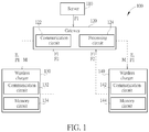
- FIG. 1 is a simplified block diagram of a remote management system 100 for wireless charging in accordance with a first example of the present invention.
- the remote management system 100 may comprise: a server 110, a gateway 120, and two wireless chargers 130, 140, wherein the wireless chargers 130, 140 are utilized for charging mobile devices such as smart phones, tablets, smart watches, smart glasses, personal digital assistants (PDA), lap top computers, digital cameras, music players, and game devices, etc.
- PDA personal digital assistants
- the server 110 may be utilized for sending a new password P1 to the gateway 120, wherein the server 110 may be a computer or a group of computers, which has the capability to manage the wireless chargers and the mobile devices, and the new password P1 is utilized in connection between the gateway 120 and the wireless chargers 130, 140, wherein the new password P1 may be a AES key for a WiFi connection or a passcode for a Bluetooth connection.
- the server 110 may be further utilized for sending IDs of the wireless chargers 130, 140 to the gateway 120 be wherein the IDs of the wireless chargers 130, 140 may be serial numbers of the wireless chargers 130, 140.
- the server 110 also may be an optional element for the remote management system 100 according to different design requirement, that is, the server 110 also may be an external element of the remote management system 100 according to different design requirement.
- the gateway 120 is coupled to the server 110, and comprises a communication circuit 122 and a processing circuit 124, wherein the communication circuit 122 may be a WiFi module or a Bluetooth module.
- the wireless charger 130 comprises a communication circuit 132 and a memory circuit 134, wherein the communication circuit 132 may be a part of a wireless power transmitter (PTX) of the wireless charger 130.
- the wireless charger 140 comprises a communication circuit 142 and a memory circuit 144, wherein the communication circuit 132 may be a part of a PTX of the wireless charger 140.
- the communication circuit 122 is utilized for receiving the new password P1 from the server 110 and sending the new password P1 to the wireless chargers 130, 140, and sending an enable signal E to both the wireless chargers 130, 140 respectively if the communication circuit 122 of the gateway 120 receives two first feedback signals F1 indicating the new password P1 is received by both the wireless chargers 130, 140. In addition, if the communication circuit 122 of the gateway 120 does not receive at least one of the first feedback signals F1 from at least one of the wireless chargers 130, 140, the communication circuit 122 of the gateway 120 will continue to send the new password P1 to the at least one of the wireless chargers 130, 140.
- the communication circuit 122 of the gateway 120 receives the first feedback signal F1 from the wireless charger 130, but does not receive the first feedback signal F1 from the wireless charger 140, the communication circuit 122 of the gateway 120 will not send the enable signal E to both the wireless chargers 130, 140 but continue to send the new password P1 to the wireless charger 140.
- the communication circuit 132 is utilized for sending the first feedback signal F1 to the gateway 120 if the communication circuit 132 of the wireless charger receives the new password P1 sent from the gateway 120, and sending a second feedback signal F2 to the gateway 120 if the communication circuit 132 of the wireless charger 130 receives the enable signal E from the gateway 120.
- the memory circuit 134 may be utilized for storing the new password P1 when the communication circuit 132 of the wireless charger 130 receives the new password P1.
- the communication circuit 142 is utilized for sending the first feedback signal F1 to the gateway 120 if the communication circuit 142 of the wireless charger 140 receives the new password P1 sent from the gateway 120, and sending a second feedback signal F2 to the gateway 120 if the communication circuit 142 of the wireless charger 140 receives the enable signal E from the gateway 120.
- the memory circuit 144 may be utilized for storing the new password P1 when the communication circuit 142 of the wireless charger 140 receives the new password P1.
- the communication circuit 122 of the gateway 120 receives the two second feedback signals F2 indicating the enable signal E is received by both the wireless chargers 130, 140, the communication circuit 122 of the gateway 120 will send a message M to both the wireless chargers 130, 140 respectively to enable the new password P1 for both the wireless chargers 130, 140.
- the communication circuit 122 of the gateway 120 does not receive at least one of the second feedback signals F2 from at least one of the wireless chargers 130, 140, the communication circuit 122 of the gateway 120 will continue to send the enable signal E to the at least one of the wireless chargers 130, 140.
- the communication circuit 122 of the gateway 120 receives the second feedback signal F2 from the wireless charger 130, but does not receive the second feedback signal F2 from the wireless charger 140, the communication circuit 122 of the gateway 120 will not send the message M to both the wireless chargers 130, 140 but continue to send the enable signal E to the wireless charger 140.
- the processing circuit 124 is utilized for restarting the communication circuit 122 of the gateway 120 after the communication circuit 122 of the gateway 120 sends the message to all the wireless chargers 130, 140 respectively to enable the new password P1 for all the wireless chargers 130, 140, wherein after the processing circuit 124 of the gateway 120 restarts the communication circuit 122 of the gateway 120, the communication circuits 132 of the wireless charger 130 re-establishes the connection with the communication circuit 122 of the gateway 120 by using the new password P1, and the communication circuits 142 of the wireless charger 140 re-establishes the connection with the communication circuit 122 of the gateway 120 by using the new password P1, too.
- the wireless charger 130 is not capable of connecting to the gateway 120 by using the new password P1, it will come back to use an old password or an original password to establish the connection.
- the wireless charger 140 is not capable of connecting to the gateway 120 by using the new password P1, it will also come back to use an old password or an original password to establish the connection.
- the gateway 120 finds that the wireless charger 130 does not reconnect back, the gateway 120 will reports this condition to the server 110.
- the gateway 120 finds that the wireless charger 140 does not reconnect back the gateway 120 will reports this condition to the server 110.
- FIG. 2 is a flowchart showing a method in accordance with operation schemes of the remote management system 100 in the above example. Provided that the result is substantially the same, the steps in FIG. 2 are not required to be executed in the exact order shown in FIG. 2 .
- the remote management method in accordance with the above example of the remote management system 100 in the present invention comprises the following steps:
- the remote management method may further comprise an additional step of utilizing a memory circuit of each wireless charger to store the new password when each wireless charger receives the new password.
- the remote management method may further comprise an additional step of utilizing the communication circuit of the gateway to keep sending the new password to the at least one of the wireless charger if the communication circuit of the gateway does not receive at least one of the first feedback signals from at least one of the wireless chargers.
- the remote management method may further comprise an additional step of utilizing the communication circuit of the gateway to keep sending the enable signal to the at least one of the wireless chargers if the communication circuit of the gateway does not receive at least one of the second feedback signals from at least one of the wireless chargers.
- the remote management method may further comprise an additional step of utilizing a processing circuit of the gateway to restart the communication circuit of the gateway after the communication circuit of the gateway sends the message to all the wireless chargers respectively to enable the new password for all the wireless chargers.
- the remote management method also may further comprise an additional step of utilizing the communication circuits of the wireless chargers re-establish connection with the communication circuit of the gateway by using the new password after the processing circuit of the gateway restarts the communication circuit of the gateway.
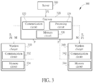
- FIG. 3 is a simplified block diagram of a remote management system 300 for wireless charging in accordance with a second example of the present invention.
- the remote management system 300 may comprise: a server 310, a gateway 320, and two wireless chargers 330, 340, wherein the wireless chargers 330, 340 are utilized for charging mobile devices such as smart phones, tablets, smart watches, smart glasses, personal digital assistants (PDA), lap top computers, digital cameras, music players, and game devices, etc.
- PDA personal digital assistants
- the server 310 may be utilized for sending a new password P1 to the gateway 320, wherein the server 310 may be a computer or a group of computers, which has the capability to manage the wireless chargers and the mobile devices, and the new password P1 is utilized in connection between the gateway 320 and the wireless chargers 330, 340, wherein the new password P1 may be a AES key for a WiFi connection or a passcode for a Bluetooth connection.
- the server 310 may be further utilized for sending IDs of the wireless chargers 330, 340 to the gateway 320 be wherein the IDs of the wireless chargers 330, 340 may be serial numbers of the wireless chargers 330, 340.
- the server 310 also may be an optional element for the remote management system 300 according to different design requirement, that is, the server 310 also may be an external element of the remote management system 300 according to different design requirement.
- the gateway 320 is coupled to the server 310, and comprises a communication circuit 322, a processing circuit 324, and a memory circuit 326, wherein the communication circuit 322 may be a WiFi module or a Bluetooth module.
- the memory circuit 326 may be utilized for storing the new password P1 when the gateway receives the new password P1 from the server 310.
- the wireless charger 330 comprises a communication circuit 332 and a memory circuit 334, wherein the communication circuit 332 may be a part of a wireless power transmitter (PTX) of the wireless charger 330.
- the wireless charger 340 comprises a communication circuit 342 and a memory circuit 344, wherein the communication circuit 332 may be a part of a PTX of the wireless charger 340.
- the communication circuit 322 is utilized for receiving the new password P1 from the server 310 and sending the new password P1 and an enable signal E to the wireless chargers 330, 340, and sending a message M to both the wireless chargers 330, 340 respectively to enable the new password P1 for both the wireless chargers 330, 340 if the communication circuit 322 of the gateway 320 receives two feedback signals F indicating the new password P1 and the enable signal E are received by both the wireless chargers 330, 340.
- the communication circuit 322 of the gateway 320 will continue to send the new password P1 and the enable signal E to the at least one of the wireless chargers 330, 340.
- the communication circuit 322 of the gateway 320 will not send the message M to both the wireless chargers 330, 340 but continue to send the new password P1 and the enable signal E to the wireless charger 340.
- the communication circuit 332 is utilized for sending the feedback signal F to the gateway 320 if the communication circuit 332 of the wireless charger receives the new password P1 and the enable signal E sent from the gateway 320.
- the memory circuit 334 may be utilized for storing the new password P1 when the communication circuit 332 of the wireless charger 330 receives the new password P1.
- the communication circuit 342 is utilized for sending the feedback signal F to the gateway 320 if the communication circuit 342 of the wireless charger 340 receives the new password P1 and the enable signal E sent from the gateway 320.
- the memory circuit 344 may be utilized for storing the new password P1 when the communication circuit 342 of the wireless charger 340 receives the new password P1.
- the processing circuit 324 is utilized for restarting the communication circuit 322 of the gateway 320 after the communication circuit 322 of the gateway 320 sends the message to all the wireless chargers 330, 340 respectively to enable the new password P1 for all the wireless chargers 330, 340, wherein after the processing circuit 324 of the gateway 320 restarts the communication circuit 322 of the gateway 320, the communication circuits 332 of the wireless charger 330 re-establishes the connection with the communication circuit 322 of the gateway 320 by using the new password P1, and the communication circuits 342 of the wireless charger 340 re-establishes the connection with the communication circuit 322 of the gateway 320 by using the new password P1, too.
- the wireless charger 330 is not capable of connecting to the gateway 320 by using the new password P1, it will come back to use an old password or an original password to establish the connection.
- the wireless charger 340 is not capable of connecting to the gateway 320 by using the new password P1, it will also come back to use an old password or an original password to establish the connection.
- the gateway 320 finds that the wireless charger 330 does not reconnect back, the gateway 320 will reports this condition to the server 310.
- the gateway 320 finds that the wireless charger 340 does not reconnect back, the gateway 320 will reports this condition to the server 310.
- the above example is only for an illustrative purpose and is not meant to be a limitation of the present invention.
- the quantity of the wireless chargers can be changed to any number according to different design requirements.
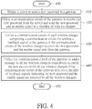
- FIG. 4 is a flowchart showing a method in accordance with operation schemes of the remote management system 300 in the above example. Provided that the result is substantially the same, the steps in FIG. 4 are not required to be executed in the exact order shown in FIG. 4 .
- the remote management method in accordance with the above example of the remote management system 300 in the present invention comprises the following steps:
- the remote management method may further comprise an additional step of utilizing a memory circuit of the gateway to store the new password when the gateway receives the new password from the server.
- the remote management method may further comprise an additional step of utilizing the communication circuit of the gateway to keep sending the new password and the enable signal to the at least one of the wireless charger if the communication circuit of the gateway does not receive at least one of the feedback signals from at least one of the wireless chargers.
- the remote management method may further comprise an additional step of utilizing a processing circuit of the gateway to restart the communication circuit of the gateway after the communication circuit of the gateway sends the message to all the wireless chargers respectively to enable the new password for all the wireless chargers.
- the remote management method also may further comprise an additional step of utilizing the communication circuits of the wireless chargers re-establish connection with the communication circuit of the gateway by using the new password after the processing circuit of the gateway restarts the communication circuit of the gateway.
- the remote management system and the remote management method for wireless charging disclosed by the present invention are capable of remotely and simultaneously changing the connection password used by a gateway and its underlying wireless chargers.
Landscapes
- Engineering & Computer Science (AREA)
- Computer Security & Cryptography (AREA)
- Theoretical Computer Science (AREA)
- General Engineering & Computer Science (AREA)
- Computer Hardware Design (AREA)
- Computer Networks & Wireless Communication (AREA)
- Physics & Mathematics (AREA)
- General Physics & Mathematics (AREA)
- Power Engineering (AREA)
- Signal Processing (AREA)
- Software Systems (AREA)
- Computing Systems (AREA)
- Human Computer Interaction (AREA)
- Mobile Radio Communication Systems (AREA)
Abstract
Description
- The present invention relates to a remote management system and a remote management method for wireless charging, and more particularly, to a remote management system and a remote management method for wireless charging capable of remotely and simultaneously changing the connection password used by a gateway and its underlying wireless chargers.
- Wireless Power Consortium (WPC) and air fuel alliance (AFA) are two leading organizations in the world for developing wireless charging standard. The document "The Qi Wireless Power Transfer System - Power Class 0 Specification" released in April 2016 describes the interaction between a wireless power transmitter (PTX) and a wireless power receiver (PRX). In this specification, Wireless charging network is a network in which every node denotes a wireless charger. In most cases, each wireless charger is connected to a gateway and the gateway is connected to a server. It means every gateway is response for managing a set of nearby wireless chargers, and for security reason, it is required to change the connection password used by the gateway and its underlying wireless chargers. By this specification, manufacturers can produce wireless charger which can provide wireless power to all the receivers which support the same specification. However, if a lot of wireless chargers are deployed in many stores, it might be important to find a way to manage them remotely since there is no user interface on the wireless charger. One design is to install a gateway which is connected to a server in every store and ask each wireless charger to connect to the gateway. Then a user can manage each wireless charger from the server through the gateway. Usually, the connection between the server and the gateway is via wire communication, but the connection between the gateway and wireless charger is via wireless communication. The resulting architecture is as follows. For security reason, normally only the charge is allowed to connect to the gateway. It implies there should be a password for establishing the connection between the gateway and the wireless charger. If the user needs to change this password, one possible way is to go to every store to reset the password for every wireless charger and the gateway. However, it will be too time consuming. A more feasible way is to change this password from the server, it means nobody needs to go to the store but just press some keys remotely to complete the job. Although it is an attractive scenario, but there exist some challenges. At first, the gateway and the wireless chargers need to change the password simultaneously, or the connection will be failed. The second, all the wireless chargers need to be updated at the same time, or some wireless chargers will lose the connection to the gateway. It implies that if the password update is failed for only one wireless charger or certain wireless chargers, but is completed for the gateway and the other wireless chargers, then the only one wireless charger or the certain wireless chargers will never be able to connect back to the gateway.
- It is therefore one of the objectives of the disclosure to provide a remote management system and a remote management method for wireless charging capable of remotely and simultaneously changing the connection password used by a gateway and its underlying wireless chargers, so as to solve the problem mentioned above.
- In accordance with an example of the present invention, a remote management system for wireless charging is disclosed. The remote management system comprises: a gateway and a plurality of wireless chargers. The gateway comprises a communication circuit for sending a new password to a plurality of wireless chargers, and sending an enable signal to all the wireless chargers respectively if the communication circuit of the gateway receives a plurality of first feedback signals indicating the new password is received by all the wireless chargers. Each wireless charger comprises a communication circuit for sending the first feedback signal to the gateway if the communication circuit of the wireless charger receives the new password sent from the gateway, and sending a second feedback signal to the gateway if the communication circuit of the wireless charger receives the enable signal from the gateway; wherein if the communication circuit of the gateway receives the second feedback signals indicating the enable signal is received by all the wireless chargers, the communication circuit of the gateway sends a message to all the wireless chargers respectively to enable the new password for all the wireless chargers.
- In accordance with an example of the present invention, a remote management method for wireless charging is disclosed. The remote management method comprises: utilizing a communication circuit of a gateway to send a new password to a plurality of wireless chargers, and send an enable signal to all the wireless chargers respectively if the communication circuit of the gateway receives a plurality of first feedback signals indicating the new password is received by all the wireless chargers; and utilizing a communication circuit of each wireless charger to send the first feedback signal to the gateway if the communication circuit of the wireless charger receives the new password sent from the gateway, and send a second feedback signal to the gateway if the communication circuit of the wireless charger receives the enable signal from the gateway; utilizing the communication circuit of the gateway to send a message to all the wireless chargers respectively to enable the new password for all the wireless chargers if the communication circuit of the gateway receives the second feedback signals indicating the enable signal is received by all the wireless chargers.
- In accordance with an example of the present invention, a remote management system for wireless charging is disclosed. A remote management system comprises: a gateway, and a plurality of wireless chargers. The gateway comprises a communication circuit sending a new password and an enable signal to a plurality of wireless chargers, and sending a message to all the wireless chargers respectively to enable the new password for all the wireless chargers if the communication circuit of the gateway receives a plurality of feedback signals indicating the new password and the enable signal are received by all the wireless chargers. Each wireless charger comprises a communication circuit for sending the feedback signal to the gateway if the communication circuit of the wireless charger receives the new password and the enable signal sent from the gateway.
- Briefly summarized, the remote management system and the remote management method for wireless charging disclosed by the present invention are capable of remotely and simultaneously changing the connection password used by a gateway and its underlying wireless chargers via a server.
-
-
FIG. 1 is a simplified block diagram of a remote management system for wireless charging in accordance with a first example of the present invention. -
FIG. 2 is a flowchart showing a method in accordance with operation schemes of the remote management system inFIG. 1 . -
FIG. 3 is a simplified block diagram of a remote management system for wireless charging in accordance with a second example of the present invention. -
FIG. 4 is a flowchart showing a method in accordance with operation schemes of the remote management system inFIG. 3 . - Certain terms are used throughout the description and following claims to refer to particular components. As one skilled in the art will appreciate, manufacturers may refer to a component by different names. This document does not intend to distinguish between components that differ in name but not function. In the following description and in the claims, the terms "include" and "comprise" are used in an open-ended fashion, and thus should be interpreted to mean "include, but not limited to". Also, the term "couple" is intended to mean either an indirect or direct electrical connection. Accordingly, if one device is coupled to another device, that connection may be through a direct electrical connection, or through an indirect electrical connection via other devices and connections.
- Please refer to
FIG. 1. FIG. 1 is a simplified block diagram of aremote management system 100 for wireless charging in accordance with a first example of the present invention. As shown inFIG. 1 , theremote management system 100 may comprise: aserver 110, agateway 120, and twowireless chargers wireless chargers server 110 may be utilized for sending a new password P1 to thegateway 120, wherein theserver 110 may be a computer or a group of computers, which has the capability to manage the wireless chargers and the mobile devices, and the new password P1 is utilized in connection between thegateway 120 and thewireless chargers server 110 may be further utilized for sending IDs of thewireless chargers gateway 120 be wherein the IDs of thewireless chargers wireless chargers server 110 also may be an optional element for theremote management system 100 according to different design requirement, that is, theserver 110 also may be an external element of theremote management system 100 according to different design requirement. - The
gateway 120 is coupled to theserver 110, and comprises acommunication circuit 122 and aprocessing circuit 124, wherein thecommunication circuit 122 may be a WiFi module or a Bluetooth module. Thewireless charger 130 comprises acommunication circuit 132 and amemory circuit 134, wherein thecommunication circuit 132 may be a part of a wireless power transmitter (PTX) of thewireless charger 130. Thewireless charger 140 comprises acommunication circuit 142 and amemory circuit 144, wherein thecommunication circuit 132 may be a part of a PTX of thewireless charger 140. - The
communication circuit 122 is utilized for receiving the new password P1 from theserver 110 and sending the new password P1 to thewireless chargers wireless chargers communication circuit 122 of thegateway 120 receives two first feedback signals F1 indicating the new password P1 is received by both thewireless chargers communication circuit 122 of thegateway 120 does not receive at least one of the first feedback signals F1 from at least one of thewireless chargers communication circuit 122 of thegateway 120 will continue to send the new password P1 to the at least one of thewireless chargers communication circuit 122 of thegateway 120 receive the first feedback signal F1 from thewireless charger 130, but does not receive the first feedback signal F1 from thewireless charger 140, thecommunication circuit 122 of thegateway 120 will not send the enable signal E to both thewireless chargers wireless charger 140. - The
communication circuit 132 is utilized for sending the first feedback signal F1 to thegateway 120 if thecommunication circuit 132 of the wireless charger receives the new password P1 sent from thegateway 120, and sending a second feedback signal F2 to thegateway 120 if thecommunication circuit 132 of thewireless charger 130 receives the enable signal E from thegateway 120. In addition, thememory circuit 134 may be utilized for storing the new password P1 when thecommunication circuit 132 of thewireless charger 130 receives the new password P1. - The
communication circuit 142 is utilized for sending the first feedback signal F1 to thegateway 120 if thecommunication circuit 142 of thewireless charger 140 receives the new password P1 sent from thegateway 120, and sending a second feedback signal F2 to thegateway 120 if thecommunication circuit 142 of thewireless charger 140 receives the enable signal E from thegateway 120. In addition, thememory circuit 144 may be utilized for storing the new password P1 when thecommunication circuit 142 of thewireless charger 140 receives the new password P1. - Next, if the
communication circuit 122 of thegateway 120 receives the two second feedback signals F2 indicating the enable signal E is received by both thewireless chargers communication circuit 122 of thegateway 120 will send a message M to both thewireless chargers wireless chargers communication circuit 122 of thegateway 120 does not receive at least one of the second feedback signals F2 from at least one of thewireless chargers communication circuit 122 of thegateway 120 will continue to send the enable signal E to the at least one of thewireless chargers communication circuit 122 of thegateway 120 receive the second feedback signal F2 from thewireless charger 130, but does not receive the second feedback signal F2 from thewireless charger 140, thecommunication circuit 122 of thegateway 120 will not send the message M to both thewireless chargers wireless charger 140. - Next, the
processing circuit 124 is utilized for restarting thecommunication circuit 122 of thegateway 120 after thecommunication circuit 122 of thegateway 120 sends the message to all thewireless chargers wireless chargers processing circuit 124 of thegateway 120 restarts thecommunication circuit 122 of thegateway 120, thecommunication circuits 132 of thewireless charger 130 re-establishes the connection with thecommunication circuit 122 of thegateway 120 by using the new password P1, and thecommunication circuits 142 of thewireless charger 140 re-establishes the connection with thecommunication circuit 122 of thegateway 120 by using the new password P1, too. In addition, if thewireless charger 130 is not capable of connecting to thegateway 120 by using the new password P1, it will come back to use an old password or an original password to establish the connection. Similarly, if thewireless charger 140 is not capable of connecting to thegateway 120 by using the new password P1, it will also come back to use an old password or an original password to establish the connection. Moreover, if thegateway 120 finds that thewireless charger 130 does not reconnect back, thegateway 120 will reports this condition to theserver 110. Similarly, thegateway 120 finds that thewireless charger 140 does not reconnect back, thegateway 120 will reports this condition to theserver 110. - Please note that the above example is only for an illustrative purpose and is not meant to be a limitation of the present invention. For example, the quantity of the wireless chargers can be changed to any number according to different design requirements.
- Please refer to
FIG. 2. FIG. 2 is a flowchart showing a method in accordance with operation schemes of theremote management system 100 in the above example. Provided that the result is substantially the same, the steps inFIG. 2 are not required to be executed in the exact order shown inFIG. 2 . The remote management method in accordance with the above example of theremote management system 100 in the present invention comprises the following steps: - Step 200: Start.
- Step 210: Utilize a server to send a new password to a gateway.
- Step 220: Utilize a communication circuit of the gateway to receive the new password from the server and send the new password to a plurality of wireless chargers.
- Step 230: Utilize a communication circuit of each wireless charger to send a first feedback signal to the gateway if the communication circuit of the wireless charger receives the new password sent from the gateway.
- Step 240: Utilize the communication circuit of the gateway to send an enable signal to all the wireless chargers respectively if the communication circuit of the gateway receives a plurality of first feedback signals indicating the new password is received by all the wireless chargers.
- Step 250: Utilize the communication circuit of each wireless charger to send a second feedback signal to the gateway if the communication circuit of the wireless charger receives the enable signal from the gateway.
- Step 260: Utilize the communication circuit of the gateway to send a message to all the wireless chargers respectively to enable the new password for all the wireless chargers if the communication circuit of the gateway receives the second feedback signals indicating the enable signal is received by all the wireless chargers.
- Step 270: End
- In another example, the remote management method may further comprise an additional step of utilizing a memory circuit of each wireless charger to store the new password when each wireless charger receives the new password. In addition, after the
Step 230, the remote management method may further comprise an additional step of utilizing the communication circuit of the gateway to keep sending the new password to the at least one of the wireless charger if the communication circuit of the gateway does not receive at least one of the first feedback signals from at least one of the wireless chargers. After theStep 250, the remote management method may further comprise an additional step of utilizing the communication circuit of the gateway to keep sending the enable signal to the at least one of the wireless chargers if the communication circuit of the gateway does not receive at least one of the second feedback signals from at least one of the wireless chargers. - In another example, after
Step 260, the remote management method may further comprise an additional step of utilizing a processing circuit of the gateway to restart the communication circuit of the gateway after the communication circuit of the gateway sends the message to all the wireless chargers respectively to enable the new password for all the wireless chargers. Next, the remote management method also may further comprise an additional step of utilizing the communication circuits of the wireless chargers re-establish connection with the communication circuit of the gateway by using the new password after the processing circuit of the gateway restarts the communication circuit of the gateway. - Please refer to
FIG. 3. FIG. 3 is a simplified block diagram of aremote management system 300 for wireless charging in accordance with a second example of the present invention. As shown inFIG. 3 , theremote management system 300 may comprise: aserver 310, agateway 320, and twowireless chargers wireless chargers server 310 may be utilized for sending a new password P1 to thegateway 320, wherein theserver 310 may be a computer or a group of computers, which has the capability to manage the wireless chargers and the mobile devices, and the new password P1 is utilized in connection between thegateway 320 and thewireless chargers server 310 may be further utilized for sending IDs of thewireless chargers gateway 320 be wherein the IDs of thewireless chargers wireless chargers server 310 also may be an optional element for theremote management system 300 according to different design requirement, that is, theserver 310 also may be an external element of theremote management system 300 according to different design requirement. - The
gateway 320 is coupled to theserver 310, and comprises acommunication circuit 322, aprocessing circuit 324, and amemory circuit 326, wherein thecommunication circuit 322 may be a WiFi module or a Bluetooth module. Thememory circuit 326 may be utilized for storing the new password P1 when the gateway receives the new password P1 from theserver 310. Thewireless charger 330 comprises acommunication circuit 332 and amemory circuit 334, wherein thecommunication circuit 332 may be a part of a wireless power transmitter (PTX) of thewireless charger 330. Thewireless charger 340 comprises acommunication circuit 342 and amemory circuit 344, wherein thecommunication circuit 332 may be a part of a PTX of thewireless charger 340. - The
communication circuit 322 is utilized for receiving the new password P1 from theserver 310 and sending the new password P1 and an enable signal E to thewireless chargers wireless chargers wireless chargers communication circuit 322 of thegateway 320 receives two feedback signals F indicating the new password P1 and the enable signal E are received by both thewireless chargers communication circuit 322 of thegateway 320 does not receive at least one of the feedback signals F from at least one of thewireless chargers communication circuit 322 of thegateway 320 will continue to send the new password P1 and the enable signal E to the at least one of thewireless chargers communication circuit 322 of thegateway 320 receive the feedback signal F from thewireless charger 330, but does not receive the feedback signal F from thewireless charger 340, thecommunication circuit 322 of thegateway 320 will not send the message M to both thewireless chargers wireless charger 340. - The
communication circuit 332 is utilized for sending the feedback signal F to thegateway 320 if thecommunication circuit 332 of the wireless charger receives the new password P1 and the enable signal E sent from thegateway 320. In addition, thememory circuit 334 may be utilized for storing the new password P1 when thecommunication circuit 332 of thewireless charger 330 receives the new password P1. Thecommunication circuit 342 is utilized for sending the feedback signal F to thegateway 320 if thecommunication circuit 342 of thewireless charger 340 receives the new password P1 and the enable signal E sent from thegateway 320. In addition, thememory circuit 344 may be utilized for storing the new password P1 when thecommunication circuit 342 of thewireless charger 340 receives the new password P1. - Next, the
processing circuit 324 is utilized for restarting thecommunication circuit 322 of thegateway 320 after thecommunication circuit 322 of thegateway 320 sends the message to all thewireless chargers wireless chargers processing circuit 324 of thegateway 320 restarts thecommunication circuit 322 of thegateway 320, thecommunication circuits 332 of thewireless charger 330 re-establishes the connection with thecommunication circuit 322 of thegateway 320 by using the new password P1, and thecommunication circuits 342 of thewireless charger 340 re-establishes the connection with thecommunication circuit 322 of thegateway 320 by using the new password P1, too. In addition, if thewireless charger 330 is not capable of connecting to thegateway 320 by using the new password P1, it will come back to use an old password or an original password to establish the connection. Similarly, if thewireless charger 340 is not capable of connecting to thegateway 320 by using the new password P1, it will also come back to use an old password or an original password to establish the connection. Moreover, if thegateway 320 finds that thewireless charger 330 does not reconnect back, thegateway 320 will reports this condition to theserver 310. Similarly, thegateway 320 finds that thewireless charger 340 does not reconnect back, thegateway 320 will reports this condition to theserver 310. - Please note that the above example is only for an illustrative purpose and is not meant to be a limitation of the present invention. For example, the quantity of the wireless chargers can be changed to any number according to different design requirements.
- Please refer to
FIG. 4. FIG. 4 is a flowchart showing a method in accordance with operation schemes of theremote management system 300 in the above example. Provided that the result is substantially the same, the steps inFIG. 4 are not required to be executed in the exact order shown inFIG. 4 . The remote management method in accordance with the above example of theremote management system 300 in the present invention comprises the following steps: - Step 400: Start.
- Step 410: Utilize a server to send a new password to a gateway.
- Step 420: Utilize a communication circuit of the gateway to receive the new password from the server and send the new password and an enable signal to a plurality of wireless chargers.
- Step 430: Utilize a communication circuit of each wireless charger comprising a communication circuit for sending a feedback signal to the gateway if the communication circuit of the wireless charger receives the new password and the enable signal sent from the gateway.
- Step 440: Utilize the communication circuit of the gateway to send a message to all the wireless chargers respectively to enable the new password for all the wireless chargers if the communication circuit of the gateway receives a plurality of feedback signals indicating the new password and the enable signal are received by all the wireless chargers.
- Step 450: End
- In another example, the remote management method may further comprise an additional step of utilizing a memory circuit of the gateway to store the new password when the gateway receives the new password from the server. In addition, after the
Step 430, the remote management method may further comprise an additional step of utilizing the communication circuit of the gateway to keep sending the new password and the enable signal to the at least one of the wireless charger if the communication circuit of the gateway does not receive at least one of the feedback signals from at least one of the wireless chargers. In another example, afterStep 260, the remote management method may further comprise an additional step of utilizing a processing circuit of the gateway to restart the communication circuit of the gateway after the communication circuit of the gateway sends the message to all the wireless chargers respectively to enable the new password for all the wireless chargers. Next, the remote management method also may further comprise an additional step of utilizing the communication circuits of the wireless chargers re-establish connection with the communication circuit of the gateway by using the new password after the processing circuit of the gateway restarts the communication circuit of the gateway. - Briefly summarized, the remote management system and the remote management method for wireless charging disclosed by the present invention are capable of remotely and simultaneously changing the connection password used by a gateway and its underlying wireless chargers.
Claims (15)
- A remote management system for wireless charging, comprising:a gateway, comprising a communication circuit for sending a new password to a plurality of wireless chargers, and sending an enable signal to all the wireless chargers respectively if the communication circuit of the gateway receives a plurality of first feedback signals indicating the new password is received by all the wireless chargers; andthe wireless chargers, each wireless charger comprising a communication circuit for sending the first feedback signal to the gateway if the communication circuit of the wireless charger receives the new password sent from the gateway, and sending a second feedback signal to the gateway if the communication circuit of the wireless charger receives the enable signal from the gateway;wherein if the communication circuit of the gateway receives the second feedback signals indicating the enable signal is received by all the wireless chargers, the communication circuit of the gateway sends a message to all the wireless chargers respectively to enable the new password for all the wireless chargers.
- The remote management system of claim 1, wherein the gateway is coupled to a server, and the new password is provided by the server.
- The remote management system of claim 2, wherein the server is further utilized for sending IDs of the wireless chargers to the gateway.
- The remote management system according to any one of the preceding claims, wherein if the communication circuit of the gateway does not receive at least one of the first feedback signals from at least one of the wireless chargers, the communication circuit of the gateway keeps sending the new password to the at least one of the wireless chargers.
- The remote management system according to any one of the preceding claims, wherein if the communication circuit of the gateway does not receive at least one of the second feedback signals from at least one of the wireless chargers, the communication circuit of the gateway keeps sending the enable signal to the at least one of the wireless chargers.
- The remote management system according to any one of the preceding claims, wherein the gateway further comprises a processing circuit for restarting the communication circuit of the gateway after the communication circuit of the gateway sends the message to all the wireless chargers respectively to enable the new password for all the wireless chargers.
- The remote management system of claim 6, wherein after the processing circuit of the gateway restarts the communication circuit of the gateway, the communication circuits of the wireless chargers re-establish connection with the communication circuit of the gateway by using the new password.
- A remote management method for wireless charging, comprising:utilizing a communication circuit of a gateway to send a new password to a plurality of wireless chargers, and send an enable signal to all the wireless chargers respectively if the communication circuit of the gateway receives a plurality of first feedback signals indicating the new password is received by all the wireless chargers,utilizing a communication circuit of each wireless charger to send the first feedback signal to the gateway if the communication circuit of the wireless charger receives the new password sent from the gateway, and send a second feedback signal to the gateway if the communication circuit of the wireless charger receives the enable signal from the gateway; andutilizing the communication circuit of the gateway to send a message to all the wireless chargers respectively to enable the new password for all the wireless chargers if the communication circuit of the gateway receives the second feedback signals indicating the enable signal is received by all the wireless chargers.
- The remote management method of claim 8, further comprising:utilizing a processing circuit of the gateway to restart the communication circuit of the gateway after the communication circuit of the gateway sends the message to all the wireless chargers respectively to enable the new password for all the wireless chargers.
- The remote management method of claim 9, further comprising:utilizing the communication circuits of the wireless chargers re-establish connection with the communication circuit of the gateway by using the new password after the processing circuit of the gateway restarts the communication circuit of the gateway.
- A remote management system for wireless charging, independently or according to claim 1, comprising:a gateway, comprising a communication circuit for sending a new password and an enable signal to a plurality of wireless chargers, and sending a message to all the wireless chargers respectively to enable the new password for all the wireless chargers if the communication circuit of the gateway receives a plurality of feedback signals indicating the new password and the enable signal are received by all the wireless chargers; andthe wireless chargers, each wireless charger comprising a communication circuit for sending the feedback signal to the gateway if the communication circuit of the wireless charger receives the new password and the enable signal sent from the gateway.
- The remote management system of claim 11, wherein the gateway is coupled to a server, and the new password is provided by the server.
- The remote management system of claim 11 or 12, wherein if the communication circuit of the gateway does not receive at least one of the feedback signals from at least one of the wireless chargers, the communication circuit of the gateway keeps sending the new password and the enable signal to the at least one of the wireless chargers.
- The remote management system according to any one of the preceding claims 11 to 13, wherein the gateway further comprises a processing circuit for restarting the communication circuit of the gateway after the communication circuit of the gateway sends the message to all the wireless chargers respectively to enable the new password for all the wireless chargers.
- The remote management system of claim 14, wherein after the processing circuit of the gateway restarts the communication circuit of the gateway, the communication circuits of the wireless chargers re-establish connection with the communication circuit of the gateway by using the new password.
Priority Applications (2)
| Application Number | Priority Date | Filing Date | Title |
|---|---|---|---|
| EP16207438.9A EP3343721A1 (en) | 2016-12-30 | 2016-12-30 | Wireless charging management system and method |
| US15/394,823 US20180188786A1 (en) | 2016-12-30 | 2016-12-30 | Remote management of gateway and wireless charger |
Applications Claiming Priority (2)
| Application Number | Priority Date | Filing Date | Title |
|---|---|---|---|
| EP16207438.9A EP3343721A1 (en) | 2016-12-30 | 2016-12-30 | Wireless charging management system and method |
| US15/394,823 US20180188786A1 (en) | 2016-12-30 | 2016-12-30 | Remote management of gateway and wireless charger |
Publications (1)
| Publication Number | Publication Date |
|---|---|
| EP3343721A1 true EP3343721A1 (en) | 2018-07-04 |
Family
ID=66813665
Family Applications (1)
| Application Number | Title | Priority Date | Filing Date |
|---|---|---|---|
| EP16207438.9A Withdrawn EP3343721A1 (en) | 2016-12-30 | 2016-12-30 | Wireless charging management system and method |
Country Status (2)
| Country | Link |
|---|---|
| US (1) | US20180188786A1 (en) |
| EP (1) | EP3343721A1 (en) |
Families Citing this family (1)
| Publication number | Priority date | Publication date | Assignee | Title |
|---|---|---|---|---|
| US10848010B2 (en) * | 2017-03-30 | 2020-11-24 | Advanced Charging Technologies Inc. | Battery management system and related methods |
Citations (5)
| Publication number | Priority date | Publication date | Assignee | Title |
|---|---|---|---|---|
| US20120287914A1 (en) * | 2011-05-10 | 2012-11-15 | Motorola Mobility, Inc. | Method and apparatus for providing wireless service to a collective of remote units by a wireless local area network |
| US20130006435A1 (en) * | 2011-07-01 | 2013-01-03 | Berrios Javier C | Solar-Powered Apparatus for Wireless Network Control of an Array of Solar Tracking Devices and Systems Based Thereon |
| EP2559589A2 (en) * | 2011-07-29 | 2013-02-20 | Kabushiki Kaisha Toshiba | Storage system |
| US20140062401A1 (en) * | 2012-08-24 | 2014-03-06 | The Regents Of The University Of California | Power control apparatus and methods for electric vehicles |
| US20150244201A1 (en) * | 2014-02-26 | 2015-08-27 | Htc Corporation | Method of Handling Wireless Charging Authentication |
-
2016
- 2016-12-30 US US15/394,823 patent/US20180188786A1/en not_active Abandoned
- 2016-12-30 EP EP16207438.9A patent/EP3343721A1/en not_active Withdrawn
Patent Citations (5)
| Publication number | Priority date | Publication date | Assignee | Title |
|---|---|---|---|---|
| US20120287914A1 (en) * | 2011-05-10 | 2012-11-15 | Motorola Mobility, Inc. | Method and apparatus for providing wireless service to a collective of remote units by a wireless local area network |
| US20130006435A1 (en) * | 2011-07-01 | 2013-01-03 | Berrios Javier C | Solar-Powered Apparatus for Wireless Network Control of an Array of Solar Tracking Devices and Systems Based Thereon |
| EP2559589A2 (en) * | 2011-07-29 | 2013-02-20 | Kabushiki Kaisha Toshiba | Storage system |
| US20140062401A1 (en) * | 2012-08-24 | 2014-03-06 | The Regents Of The University Of California | Power control apparatus and methods for electric vehicles |
| US20150244201A1 (en) * | 2014-02-26 | 2015-08-27 | Htc Corporation | Method of Handling Wireless Charging Authentication |
Non-Patent Citations (1)
| Title |
|---|
| THE QI WIRELESS POWER TRANSFER SYSTEM - POWER CLASS 0 SPECIFICATION, April 2016 (2016-04-01) |
Also Published As
| Publication number | Publication date |
|---|---|
| US20180188786A1 (en) | 2018-07-05 |
Similar Documents
| Publication | Publication Date | Title |
|---|---|---|
| US8938222B2 (en) | Event notification device and event notification system | |
| JP6053442B2 (en) | COMMUNICATION SYSTEM, RECEPTION DEVICE, TRANSMISSION DEVICE, CONTROL METHOD, AND PROGRAM | |
| US9468027B2 (en) | Method for controlling a Bluetooth connection | |
| US20140152235A1 (en) | Apparatus and methods for utilizing a wireless charger in a wireless docking environment | |
| EP3125513A1 (en) | Multi-mode power saving multimedia transmission method and system | |
| CN102882560A (en) | Bluetooth low energy approach detections through vehicle paired capable devices | |
| CN112119673B (en) | Electronic device supporting multiple wireless communication protocols and method thereof | |
| US20150092231A1 (en) | Wireless Communication Apparatus | |
| CN103685373A (en) | Data uploading device and data uploading method | |
| CA2871994C (en) | Short-range wireless communication device | |
| US10581273B2 (en) | Wireless charging receiver group authentication | |
| WO2012111340A1 (en) | Wireless communication system, wireless communication device, and wireless communication method | |
| CN104159259A (en) | A wireless communication method and a wireless communication apparatus | |
| KR20190047598A (en) | Method and device of transmitting data | |
| EP3702909B1 (en) | Software update device and software update method using same | |
| US20120045992A1 (en) | Apparatus and method for sharing data in portable terminal | |
| CN103209418A (en) | Mobile terminal and wireless fidelity (WIFI) hot spot information updating method thereof | |
| WO2018125561A1 (en) | Emergency call setup in wireless networks | |
| JP2012243247A (en) | Firmware update system of video device | |
| CN106465454B (en) | Wireless communication system and communication method | |
| EP3082376B1 (en) | Network device discovery method and network device discovery system | |
| US20180188786A1 (en) | Remote management of gateway and wireless charger | |
| CN111478830A (en) | Remote operation system, communication device, and computer program | |
| KR101884753B1 (en) | Application for managing charging circuit and system using the same | |
| CN102883042B (en) | Mobile communication terminal application calling method and terminal |
Legal Events
| Date | Code | Title | Description |
|---|---|---|---|
| PUAI | Public reference made under article 153(3) epc to a published international application that has entered the european phase |
Free format text: ORIGINAL CODE: 0009012 |
|
| STAA | Information on the status of an ep patent application or granted ep patent |
Free format text: STATUS: REQUEST FOR EXAMINATION WAS MADE |
|
| 17P | Request for examination filed |
Effective date: 20161230 |
|
| AK | Designated contracting states |
Kind code of ref document: A1 Designated state(s): AL AT BE BG CH CY CZ DE DK EE ES FI FR GB GR HR HU IE IS IT LI LT LU LV MC MK MT NL NO PL PT RO RS SE SI SK SM TR |
|
| AX | Request for extension of the european patent |
Extension state: BA ME |
|
| RBV | Designated contracting states (corrected) |
Designated state(s): AL AT BE BG CH CY CZ DE DK EE ES FI FR GB GR HR HU IE IS IT LI LT LU LV MC MK MT NL NO PL PT RO RS SE SI SK SM TR |
|
| R17P | Request for examination filed (corrected) |
Effective date: 20161230 |
|
| GRAP | Despatch of communication of intention to grant a patent |
Free format text: ORIGINAL CODE: EPIDOSNIGR1 |
|
| STAA | Information on the status of an ep patent application or granted ep patent |
Free format text: STATUS: GRANT OF PATENT IS INTENDED |
|
| RIC1 | Information provided on ipc code assigned before grant |
Ipc: G06F 21/35 20130101ALI20200416BHEP Ipc: G06F 21/45 20130101ALI20200416BHEP Ipc: H04W 88/16 20090101ALI20200416BHEP Ipc: H02J 50/40 20160101ALI20200416BHEP Ipc: H04L 29/06 20060101ALI20200416BHEP Ipc: H02J 50/80 20160101AFI20200416BHEP Ipc: H02J 7/02 20160101ALI20200416BHEP Ipc: G06F 1/26 20060101ALI20200416BHEP Ipc: H04W 12/04 20090101ALI20200416BHEP Ipc: H04W 12/00 20090101ALI20200416BHEP Ipc: H02J 7/00 20060101ALI20200416BHEP Ipc: G06F 1/16 20060101ALI20200416BHEP |
|
| INTG | Intention to grant announced |
Effective date: 20200507 |
|
| STAA | Information on the status of an ep patent application or granted ep patent |
Free format text: STATUS: THE APPLICATION IS DEEMED TO BE WITHDRAWN |
|
| 18D | Application deemed to be withdrawn |
Effective date: 20200918 |