EP3343694A1 - Antenna device for mobile terminal and mobile terminal - Google Patents
Antenna device for mobile terminal and mobile terminal Download PDFInfo
- Publication number
- EP3343694A1 EP3343694A1 EP17182742.1A EP17182742A EP3343694A1 EP 3343694 A1 EP3343694 A1 EP 3343694A1 EP 17182742 A EP17182742 A EP 17182742A EP 3343694 A1 EP3343694 A1 EP 3343694A1
- Authority
- EP
- European Patent Office
- Prior art keywords
- slot
- mobile terminal
- antenna
- antenna device
- feeding point
- Prior art date
- Legal status (The legal status is an assumption and is not a legal conclusion. Google has not performed a legal analysis and makes no representation as to the accuracy of the status listed.)
- Granted
Links
Images

Classifications
-
- H—ELECTRICITY
- H01—ELECTRIC ELEMENTS
- H01Q—ANTENNAS, i.e. RADIO AERIALS
- H01Q1/00—Details of, or arrangements associated with, antennas
- H01Q1/12—Supports; Mounting means
- H01Q1/22—Supports; Mounting means by structural association with other equipment or articles
- H01Q1/24—Supports; Mounting means by structural association with other equipment or articles with receiving set
- H01Q1/241—Supports; Mounting means by structural association with other equipment or articles with receiving set used in mobile communications, e.g. GSM
- H01Q1/242—Supports; Mounting means by structural association with other equipment or articles with receiving set used in mobile communications, e.g. GSM specially adapted for hand-held use
- H01Q1/243—Supports; Mounting means by structural association with other equipment or articles with receiving set used in mobile communications, e.g. GSM specially adapted for hand-held use with built-in antennas
-
- H—ELECTRICITY
- H01—ELECTRIC ELEMENTS
- H01Q—ANTENNAS, i.e. RADIO AERIALS
- H01Q13/00—Waveguide horns or mouths; Slot antennas; Leaky-waveguide antennas; Equivalent structures causing radiation along the transmission path of a guided wave
- H01Q13/10—Resonant slot antennas
-
- H—ELECTRICITY
- H01—ELECTRIC ELEMENTS
- H01Q—ANTENNAS, i.e. RADIO AERIALS
- H01Q5/00—Arrangements for simultaneous operation of antennas on two or more different wavebands, e.g. dual-band or multi-band arrangements
- H01Q5/30—Arrangements for providing operation on different wavebands
- H01Q5/307—Individual or coupled radiating elements, each element being fed in an unspecified way
- H01Q5/314—Individual or coupled radiating elements, each element being fed in an unspecified way using frequency dependent circuits or components, e.g. trap circuits or capacitors
-
- H—ELECTRICITY
- H01—ELECTRIC ELEMENTS
- H01Q—ANTENNAS, i.e. RADIO AERIALS
- H01Q5/00—Arrangements for simultaneous operation of antennas on two or more different wavebands, e.g. dual-band or multi-band arrangements
- H01Q5/30—Arrangements for providing operation on different wavebands
- H01Q5/307—Individual or coupled radiating elements, each element being fed in an unspecified way
- H01Q5/314—Individual or coupled radiating elements, each element being fed in an unspecified way using frequency dependent circuits or components, e.g. trap circuits or capacitors
- H01Q5/335—Individual or coupled radiating elements, each element being fed in an unspecified way using frequency dependent circuits or components, e.g. trap circuits or capacitors at the feed, e.g. for impedance matching
Definitions
- the present disclosure relates to a field of mobile terminals, and more particularly to an antenna device for a mobile terminal and a mobile terminal having the same.
- the main types of antenna for mobile terminals are a planar inverted-F antenna (PIFA), an inverted-F antenna (IFA), a unipolar antenna and a loop antenna.
- PIFA planar inverted-F antenna
- IFA inverted-F antenna
- a unipolar antenna unipolar antenna
- loop antenna unipolar antenna
- these antennas could not efficiently send or receive electromagnetic signals when applied on a mobile terminal having a metal shell.
- Embodiments of the present disclosure seek to solve at least one of the problems existing in the related art to at least some extent.
- a first objective of the present disclosure is to provide an antenna device for a mobile terminal.
- the antenna device can guarantee efficient radiation or reception of electromagnetic signals even the shell is made of metal, realize a three-in-one antenna by single feeding and matching network and improve the signal intensity for communication.
- a second objective of the present disclosure is to provide a mobile terminal.
- an antenna device for a mobile terminal includes a slot, a connecting assembly, a first capacitor and a match circuit.
- the slot is defined in a shell of the mobile terminal.
- the slot separates the shell into a first part and a second part, and the first part is configured to couple with a mainboard via a feeding point to form a slot antenna.
- the connecting assembly connects the first part with the second part.
- the first capacitor couples the first part with the feeding point.
- the match circuit couples the first part with the feeding point.
- the slot is defined in the shell of the mobile terminal.
- the shell is divided into the first part and the second part by the slot, and the mainboard is coupled to the first part via the feeding point, thus forming the slot antenna.
- the first part is coupled with the feeding point via the first capacitor, and the match circuit couples the first part with the feeding point. That is, due to the structure of the slot antenna, the antenna device may guarantee the efficient radiation or reception of electromagnetic signals even the shell is made of metal, realize a three-in-one antenna by single feeding and matching network and improve the signal intensity for communication.
- the antenna device of the mobile terminal may have following additional technical features.
- the slot antenna covers a frequency in a range of at least one of 2.4 to 2.48 GHz and 5.1 to 5.85 GHz to form a WIFI communication antenna and the slot antenna is adjusted to cover the frequency in a range of 1.5 to 1.6GHz by the match circuit to form a GPS antenna.
- the slot has a C-shape or a U-shape.
- the slot includes a straight line section, a first bent section, a second bent section.
- the straight line section includes a first end and a second end opposite to the first end.
- the first bent section is connected with the first end of the straight line section.
- the second bent section is connected with the second end of the straight line section.
- the match circuit includes a second capacitor and a first inductor connected with the second capacitor.
- the connecting assembly is a metal connecting sheet.
- the connecting assembly is connected with the first part and the second part by means of laser welding.
- the number of the connecting assemblies is 1 to 4.
- the slot is filled with an insulator, preferably, a plastic material.
- a mobile terminal including a shell, a mainboard, and an antenna device.
- the antenna device includes a slot, a connecting assembly a first capacitor and a match circuit.
- the slot is provided in the shell of the mobile terminal.
- the slot divides the shell into a first part and a second part, and the first part is coupled to the mainboard via a feeding point to form a slot antenna.
- the connecting assembly connects the first part to the second part.
- the first capacitor is connected between the first part and the feeding point.
- the match circuit is connected between the first part and the feeding point.
- the slot is defined in the shell of the mobile terminal.
- the shell is divided into the first part and the second part by the slot, and the mainboard is coupled to the first part via the feeding point, thus forming the slot antenna.
- the first part is coupled with the feeding point via the first capacitor, and the match circuit couples the first part with the feeding point. That is, due to the structure of the slot antenna, the antenna device may guarantee the efficient radiation or reception of electromagnetic signals even the shell is made of metal, realize a three-in-one antenna by single feeding and matching network and improve the signal intensity for communication.
- the slot antenna covers a frequency in a range of at least one of 2.4 to 2.48 GHz and 5.1 to 5.85 GHz to form a WIFI communication antenna and the slot antenna is adjusted to cover the frequency in a range of 1.5 to 1.6GHz by the match circuit to form a GPS antenna.
- the slot has a C-shape or a U-shape.
- the slot includes a straight line section, a first bent section, a second bent section.
- the straight line section includes a first end and a second end opposite to the first end.
- the first bent section is connected with the first end of the straight line section.
- the second bent section is connected with the second end of the straight line section.
- the mobile terminal further includes a camera assembly.
- the feeding point is disposed between the camera assembly and the first bent section.
- the antenna device further includes a spring assembly.
- the camera assembly is connected with the connecting assembly by the spring assembly.
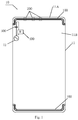
- Fig. 1 is a schematic view of an antenna device for a mobile terminal according to an embodiment of the present disclosure.
- the antenna device according to the embodiments of the present disclosure may be arranged in a mobile terminal.
- the mobile terminal may be a mobile phone, a tablet computer or the like.
- the mobile terminal is a mobile phone.
- the antenna device for the mobile terminal may include a slot 100, a connecting assembly 200, a first capacitor 300 and a match circuit 400.
- the slot 100 is defined in a shell 11 of the mobile terminal 10, separates the shell 11 into a first part 11A and a second part 11B, and the first part 11A couples with a mainboard of the mobile terminal 10 by a feeding point 12 to form a slot antenna.
- the slot antenna may be functioned by the slot, the feeding point and (electrical) connections between the first part 11A and the feeding point.
- the connecting assembly 200 may couples to the first part 11A with the second part 11B to electrically conductively connect the first part 11A and the second part 11B.
- the first capacitor 300 is coupled between the first part 11A and the feeding point 12.
- the match circuit 400 is coupled between the first part 11A and the feeding point 12.
- the number of the slots 100 may be two, for improving the radiation efficiency of the antenna device and the mobile terminal.
- one slot 100 may be defined in each of two end parts of the shell 11 of the mobile terminal 10.
- the number of the slots 100 is dependent on actual requirements. No specific restrictions are made here.
- the slot 100 may be filled with an insulator such as plastics to keep the integrity of all parts of the shell 11.
- the shell 11 is divided in two parts by the slot 100 on the shell 11, i.e. the first part 11A and the second part 11B.
- the first part 11A and the second part 11B may be electrically conductively connected by the connecting assembly 200 to form a closed circuit.
- the shell 11 of the mobile terminal 10 may be a whole-metal shell, i.e. a shell made of only a metal. Therefore, as an example, the connecting assembly 200 may be a metal connecting sheet.
- the connecting assembly 200 may be connected with the first part 11A and the second part 11B by means of laser welding. In other words, the connecting assembly 200 may be connected with the first part 11A and the second part 11B by means of laser welding to realize electrical connections.
- the number and the position of the connecting assemblies 200 may be varied depending on actual requirements. It needs to be illustrated that, in one embodiment of the present disclosure, the number of the connecting assemblies 200 may be 1 to 4. For example, as shown in Fig. 1 , there are three connecting assemblies 200 and they are disposed at different positions. Each of the connecting assemblies 200 is connected with the first part 11A and the second part 11B by means of laser welding.
- the feeding point 12 may be disposed between the first part 11A and the mainboard.
- the feeding point 12 may be a feed source of GPS/WIFI.
- the feed source of GPS/WIFI thus feeds the first part 11A through the first capacitor 300 to form the slot antenna.
- the slot antenna covers a frequency in a range of 2.4-2.48GHz/5.1-5.85GHz, i.e. at least one of 2.4 to 2.48 GHz and 5.1 to 5.85 GHz to form a WIFI communication antenna and the match circuit 400 may be configured to adjust the slot antenna to cover the frequency in a range of 1.5 to 1.6GHz to form a GPS antenna.
- the feeding point 12 may be a feed source of GPS/WIFI which feeds the first part 11A through the first capacitor 300 to form the slot antenna.
- the capacitance value of the first capacitor 300 may be in a range of 0.5pF to 2pF.
- the slot antenna may cover a frequency in a range of 2.4-2.48GHz/5.1-5.85GHz, i.e. at least one of 2.4 to 2.48 GHz and 5.1 to 5.85 GHz to form a WIFI communication antenna and the match circuit 400 may be configured to adjust the slot antenna to cover the frequency in a range of 1.5 to 1.6GHz to form a GPS antenna. Therefore, a three-in-one antenna can be realized in a limited space.
- the match circuit 400 may include a second capacitor and a first inductor connected in series.
- the match circuit 400 may be a series resonator consisting of one second capacitor and one first inductor. It may be appreciated that the specific values of the second capacitor and the first inductor in the match circuit 400 may be determined depending on actual requirements. Therefore, the slot antenna may be adjusted by the match circuit 400 to a corresponding frequency range to meet the requirements of the antenna.
- the slot 100 has a C-shape or a U-shape.
- the slot may include a straight line section 111, a first bent section 112 and a second bent section 113.
- the first bent section 112 is connected with a first end of the straight line section 111 and the second bent section 113 is connected with a second end of the straight line section 111.
- the slot 100 may consist of the straight line section 111, the first bent section 112 and the second bent section 113. That is, the horizontal section of the slot 100 may be the straight line section 111. With respect to the slot shown in Fig. 2 , the first bent section 112 may be on the left of the straight line section 111 and the second bent section 113 may be on the right of the straight line section 111. Therefore, based on the appearance and the structure of the C-shape or U-shape of the slot, antenna properties of 2.4 G WIFI/5G WIFI and GPS are achieved because of the structure by single feeding and matching network.
- the mobile terminal 10 may include a camera assembly 13.
- the feeing point 12 is disposed between the camera assembly 13 and the first bent section 112.
- the camera assembly 13 may be disposed at the upper part of the mobile terminal to facilitate the user to shoot a picture using the camera assembly of the mobile terminal.
- the camera assembly 13 may be a dual camera.
- the camera assembly 13 is disposed near the first bent section 112, for example, the camera assembly 13 is disposed on the right of the first bent section 112 and the feeding point 12.
- the feeding point 12 is thus disposed between the camera assembly 13 and the first bent section 112.
- the antenna device further includes a spring assembly 500, by which the camera assembly 13 is connected with the connecting assembly 200.
- the number of the spring assemblies 500 may be two, each of them is arranged at one of two ends of the camera assembly 13.
- the camera assembly 13 may be connected with the connecting assemblies 200.
- the spring assembly 500 is grounded, by which the camera assembly 13 is fixed.
- the camera assembly 13 is grounded to avoid its influence on the antenna.
- the slot is defined in the shell of the mobile terminal.
- the slot separates the shell into a first part and a second part, and the first part is configured to couple with a mainboard via a feeding point to form a slot antenna.
- the first part and the second part are connected by the connecting assembly.
- the first capacitor couples the first part with the feeding point.
- the match circuit couples the first part with the feeding point. That is, due to the structure of the slot, the antenna device may guarantee the efficient radiation or reception of electromagnetic signals even the shell is made of a metal, realize a three-in-one antenna by single feeding and matching network and improve the signal intensity for communication.
- a mobile terminal is further provided in embodiments of the present disclosure.
- Fig. 4 is a block diagram of a mobile terminal according to an embodiment of the present disclosure. It should be noted that the mobile terminal according to the embodiments of the present disclosure may be a mobile phone, a tablet computer and the like. In an embodiment of the present disclosure, the mobile terminal is a mobile phone.
- the mobile terminal 10 may include an antenna device 20.
- the antenna device 20 may be any antenna device according to any one of the above embodiments. That is, the specific structure and function of the antenna device 20 may refer to the description for the antenna device of any embodiments above in Fig. 1 to Fig. 3 , which are no more described in detail here.
- the slot is provided in the shell of the mobile terminal.
- the slot divides the shell into a first part and a second part, and the first part is configured to be connected with a mainboard via a feeding point to form a slot antenna.
- the connecting assembly connects the first part with the second part.
- the first capacitor is connected between the first part and the feeding point.
- the match circuit is connected between the first part and the feeding point. That is, due to the structure of the slot, the antenna device may guarantee the efficient radiation or reception of electromagnetic signals even the shell is made of a metal, realize a three-in-one antenna by single feeding and matching network and improve the signal intensity for communication.
- first and second are used herein for purposes of description and are not intended to indicate or imply relative importance or significance or to imply the number of indicated technical features.
- the feature defined with “first” and “second” may comprise one or more of this feature.
- a plurality of means two or more than two, unless specified otherwise.
- the terms “mounted,” “connected,” “coupled” and “fixed” and variations thereof are used broadly and encompass such as mechanical or electrical mountings, connections and couplings, also can be inner mountings, connections and couplings of two components, and further can be direct and indirect mountings, connections, and couplings, which can be understood by those skilled in the art according to the detail embodiment of the present disclosure.
- a structure in which a first feature is "on" or “below” a second feature may include an embodiment in which the first feature is in direct contact with the second feature, and may also include an embodiment in which the first feature and the second feature are not in direct contact with each other, but are contacted via an additional feature formed therebetween.
- a first feature "on,” “above,” or “on top of” a second feature may include an embodiment in which the first feature is right or obliquely “on,” “above,” or “on top of” the second feature, or just means that the first feature is at a height higher than that of the second feature; while a first feature “below,” “under,” or “on bottom of” a second feature may include an embodiment in which the first feature is right or obliquely “below,” “under,” or “on bottom of” the second feature, or just means that the first feature is at a height lower than that of the second feature.
Landscapes
- Engineering & Computer Science (AREA)
- Computer Networks & Wireless Communication (AREA)
- Telephone Set Structure (AREA)
- Support Of Aerials (AREA)
Abstract
Description
- The present disclosure relates to a field of mobile terminals, and more particularly to an antenna device for a mobile terminal and a mobile terminal having the same.
- With developments of mobile communication, there are various types and materials developed for mobile terminals, especially for mobile phones. Recently, it has become increasingly popular to design the rear cover as metal shells because of the favorable appearance and good touching feel of the metal shell and the better wear-resistance compared with plastic shells such as polycarbonate (PC) or acrylonitrile butadiene styrene copolymer (ABS) shells.
- At present, the main types of antenna for mobile terminals, particularly for mobile phones, are a planar inverted-F antenna (PIFA), an inverted-F antenna (IFA), a unipolar antenna and a loop antenna. However, these antennas could not efficiently send or receive electromagnetic signals when applied on a mobile terminal having a metal shell.
- Embodiments of the present disclosure seek to solve at least one of the problems existing in the related art to at least some extent.
- Accordingly, a first objective of the present disclosure is to provide an antenna device for a mobile terminal. The antenna device can guarantee efficient radiation or reception of electromagnetic signals even the shell is made of metal, realize a three-in-one antenna by single feeding and matching network and improve the signal intensity for communication.
- A second objective of the present disclosure is to provide a mobile terminal.
- In a first aspect of the present disclosure, an antenna device for a mobile terminal is provided. The antenna device includes a slot, a connecting assembly, a first capacitor and a match circuit. The slot is defined in a shell of the mobile terminal. The slot separates the shell into a first part and a second part, and the first part is configured to couple with a mainboard via a feeding point to form a slot antenna. The connecting assembly connects the first part with the second part. The first capacitor couples the first part with the feeding point. The match circuit couples the first part with the feeding point.
- According to the antenna device for the mobile terminal of embodiments of the present disclosure, the slot is defined in the shell of the mobile terminal. The shell is divided into the first part and the second part by the slot, and the mainboard is coupled to the first part via the feeding point, thus forming the slot antenna. The first part is coupled with the feeding point via the first capacitor, and the match circuit couples the first part with the feeding point. That is, due to the structure of the slot antenna, the antenna device may guarantee the efficient radiation or reception of electromagnetic signals even the shell is made of metal, realize a three-in-one antenna by single feeding and matching network and improve the signal intensity for communication.
- Furthermore, the antenna device of the mobile terminal according to embodiments of the present disclosure may have following additional technical features.
- In an embodiment of present disclosure, the slot antenna covers a frequency in a range of at least one of 2.4 to 2.48 GHz and 5.1 to 5.85 GHz to form a WIFI communication antenna and the slot antenna is adjusted to cover the frequency in a range of 1.5 to 1.6GHz by the match circuit to form a GPS antenna.
- In an embodiment of present disclosure, the slot has a C-shape or a U-shape.
- In an embodiment of present disclosure, the slot includes a straight line section, a first bent section, a second bent section. The straight line section includes a first end and a second end opposite to the first end. The first bent section is connected with the first end of the straight line section. The second bent section is connected with the second end of the straight line section.
- In an embodiment of present disclosure, the match circuit includes a second capacitor and a first inductor connected with the second capacitor.
- In an embodiment of present disclosure, the connecting assembly is a metal connecting sheet.
- In an embodiment of present disclosure, the connecting assembly is connected with the first part and the second part by means of laser welding.
- In an embodiment of present disclosure, the number of the connecting assemblies is 1 to 4.
- In an embodiment of present disclosure, the slot is filled with an insulator, preferably, a plastic material.
- In a second aspect of the present disclosure, a mobile terminal is provided, including a shell, a mainboard, and an antenna device. The antenna device includes a slot, a connecting assembly a first capacitor and a match circuit. The slot is provided in the shell of the mobile terminal. The slot divides the shell into a first part and a second part, and the first part is coupled to the mainboard via a feeding point to form a slot antenna. The connecting assembly connects the first part to the second part. The first capacitor is connected between the first part and the feeding point. The match circuit is connected between the first part and the feeding point.
- According to the mobile terminal of the embodiments of the present disclosure, in the antenna device, the slot is defined in the shell of the mobile terminal. The shell is divided into the first part and the second part by the slot, and the mainboard is coupled to the first part via the feeding point, thus forming the slot antenna. The first part is coupled with the feeding point via the first capacitor, and the match circuit couples the first part with the feeding point. That is, due to the structure of the slot antenna, the antenna device may guarantee the efficient radiation or reception of electromagnetic signals even the shell is made of metal, realize a three-in-one antenna by single feeding and matching network and improve the signal intensity for communication.
- In an embodiment of present disclosure, the slot antenna covers a frequency in a range of at least one of 2.4 to 2.48 GHz and 5.1 to 5.85 GHz to form a WIFI communication antenna and the slot antenna is adjusted to cover the frequency in a range of 1.5 to 1.6GHz by the match circuit to form a GPS antenna.
- In an embodiment of present disclosure, the slot has a C-shape or a U-shape.
- In an embodiment of present disclosure, the slot includes a straight line section, a first bent section, a second bent section. The straight line section includes a first end and a second end opposite to the first end. The first bent section is connected with the first end of the straight line section. The second bent section is connected with the second end of the straight line section.
- In an embodiment of present disclosure, the mobile terminal further includes a camera assembly. The feeding point is disposed between the camera assembly and the first bent section.
- In an embodiment of present disclosure, the antenna device further includes a spring assembly. The camera assembly is connected with the connecting assembly by the spring assembly.
- Additional aspects and advantages of embodiments of the present disclosure will be given in part in the following descriptions, become apparent in part from the following descriptions, or be learned from the practice of the embodiments of the present disclosure.
- These and other aspects and advantages of embodiments of the present disclosure will become apparent and more readily appreciated from the following descriptions made with reference to the drawings as described below.
-
Fig. 1 is a schematic view of an antenna device for a mobile terminal according to an embodiment of the present disclosure. -
Fig. 2 is a schematic view of an antenna device for a mobile terminal according to another embodiment of the present disclosure. -
Fig. 3 is a schematic view of an antenna device for a mobile terminal according to a further embodiment of the present disclosure. -
Fig. 4 is a block diagram of a mobile terminal according to an embodiment of the present disclosure. - Reference will be made in detail to embodiments of the present disclosure. The embodiments described herein with reference to drawings are explanatory, illustrative, and used to generally understand the present disclosure. The embodiments shall not be construed to limit the present disclosure. The same or similar elements and the elements having same or similar functions are denoted by like reference numerals throughout the descriptions.
- Reference will be made to the drawings to describe an antenna device for a mobile terminal and the mobile terminal with the same.
-
Fig. 1 is a schematic view of an antenna device for a mobile terminal according to an embodiment of the present disclosure. The antenna device according to the embodiments of the present disclosure may be arranged in a mobile terminal. The mobile terminal may be a mobile phone, a tablet computer or the like. In the illustrated embodiment of the present disclosure, the mobile terminal is a mobile phone. - As shown in
Fig. 1 , the antenna device for the mobile terminal may include aslot 100, a connectingassembly 200, afirst capacitor 300 and amatch circuit 400. As shown inFig. 1 , theslot 100 is defined in ashell 11 of themobile terminal 10, separates theshell 11 into afirst part 11A and asecond part 11B, and thefirst part 11A couples with a mainboard of themobile terminal 10 by afeeding point 12 to form a slot antenna. In other words, the slot antenna may be functioned by the slot, the feeding point and (electrical) connections between thefirst part 11A and the feeding point. The connectingassembly 200 may couples to thefirst part 11A with thesecond part 11B to electrically conductively connect thefirst part 11A and thesecond part 11B. Thefirst capacitor 300 is coupled between thefirst part 11A and thefeeding point 12. Thematch circuit 400 is coupled between thefirst part 11A and thefeeding point 12. - It may be appreciated that in an embodiment of the present disclosure the number of the
slots 100 may be two, for improving the radiation efficiency of the antenna device and the mobile terminal. For example, as shown inFig. 1 , oneslot 100 may be defined in each of two end parts of theshell 11 of themobile terminal 10. For example, as shown inFig. 1 , there may be twoslots 100. It may be appreciated that the number of theslots 100 is dependent on actual requirements. No specific restrictions are made here. Furthermore, theslot 100 may be filled with an insulator such as plastics to keep the integrity of all parts of theshell 11. - As shown in
Fig. 1 , theshell 11 is divided in two parts by theslot 100 on theshell 11, i.e. thefirst part 11A and thesecond part 11B. Thefirst part 11A and thesecond part 11B may be electrically conductively connected by the connectingassembly 200 to form a closed circuit. - In embodiments of the present disclosure, the
shell 11 of themobile terminal 10 may be a whole-metal shell, i.e. a shell made of only a metal. Therefore, as an example, the connectingassembly 200 may be a metal connecting sheet. The connectingassembly 200 may be connected with thefirst part 11A and thesecond part 11B by means of laser welding. In other words, the connectingassembly 200 may be connected with thefirst part 11A and thesecond part 11B by means of laser welding to realize electrical connections. - It may be appreciated that the number and the position of the connecting
assemblies 200 may be varied depending on actual requirements. It needs to be illustrated that, in one embodiment of the present disclosure, the number of the connectingassemblies 200 may be 1 to 4. For example, as shown inFig. 1 , there are three connectingassemblies 200 and they are disposed at different positions. Each of the connectingassemblies 200 is connected with thefirst part 11A and thesecond part 11B by means of laser welding. - In an embodiment of the present disclosure, the
feeding point 12 may be disposed between thefirst part 11A and the mainboard. Thefeeding point 12 may be a feed source of GPS/WIFI. The feed source of GPS/WIFI thus feeds thefirst part 11A through thefirst capacitor 300 to form the slot antenna. In an embodiment of the present disclosure, the slot antenna covers a frequency in a range of 2.4-2.48GHz/5.1-5.85GHz, i.e. at least one of 2.4 to 2.48 GHz and 5.1 to 5.85 GHz to form a WIFI communication antenna and thematch circuit 400 may be configured to adjust the slot antenna to cover the frequency in a range of 1.5 to 1.6GHz to form a GPS antenna. - Specifically, the
feeding point 12 may be a feed source of GPS/WIFI which feeds thefirst part 11A through thefirst capacitor 300 to form the slot antenna. In an embodiment of the present disclosure, the capacitance value of thefirst capacitor 300 may be in a range of 0.5pF to 2pF. Thus, the slot antenna may cover a frequency in a range of 2.4-2.48GHz/5.1-5.85GHz, i.e. at least one of 2.4 to 2.48 GHz and 5.1 to 5.85 GHz to form a WIFI communication antenna and thematch circuit 400 may be configured to adjust the slot antenna to cover the frequency in a range of 1.5 to 1.6GHz to form a GPS antenna. Therefore, a three-in-one antenna can be realized in a limited space. - As an example, the
match circuit 400 may include a second capacitor and a first inductor connected in series. In other words, thematch circuit 400 may be a series resonator consisting of one second capacitor and one first inductor. It may be appreciated that the specific values of the second capacitor and the first inductor in thematch circuit 400 may be determined depending on actual requirements. Therefore, the slot antenna may be adjusted by thematch circuit 400 to a corresponding frequency range to meet the requirements of the antenna. - In order to beautify the appearance of the mobile terminal, in an embodiment of the present disclosure, the
slot 100 has a C-shape or a U-shape. In the embodiment of the present disclosure, as shown inFig. 2 , the slot may include astraight line section 111, a firstbent section 112 and a secondbent section 113. The firstbent section 112 is connected with a first end of thestraight line section 111 and the secondbent section 113 is connected with a second end of thestraight line section 111. - For example, as shown in
Fig. 2 , theslot 100 may consist of thestraight line section 111, the firstbent section 112 and the secondbent section 113. That is, the horizontal section of theslot 100 may be thestraight line section 111. With respect to the slot shown inFig. 2 , the firstbent section 112 may be on the left of thestraight line section 111 and the secondbent section 113 may be on the right of thestraight line section 111. Therefore, based on the appearance and the structure of the C-shape or U-shape of the slot, antenna properties of 2.4 G WIFI/5G WIFI and GPS are achieved because of the structure by single feeding and matching network. - In an embodiment of the present disclosure, in the case of the slot including the straight line section, the first bent section and the second bent section, as shown in
Fig. 3 , themobile terminal 10 may include acamera assembly 13. Thefeeing point 12 is disposed between thecamera assembly 13 and the firstbent section 112. - For example, as shown in
Fig. 3 , thecamera assembly 13 may be disposed at the upper part of the mobile terminal to facilitate the user to shoot a picture using the camera assembly of the mobile terminal. Thecamera assembly 13 may be a dual camera. Thecamera assembly 13 is disposed near the firstbent section 112, for example, thecamera assembly 13 is disposed on the right of the firstbent section 112 and thefeeding point 12. Thefeeding point 12 is thus disposed between thecamera assembly 13 and the firstbent section 112. - In order to fix the camera assembly, in an embodiment of the present disclosure, as shown in
Fig. 3 , the antenna device further includes aspring assembly 500, by which thecamera assembly 13 is connected with the connectingassembly 200. - For example, as shown in
Fig. 3 , the number of thespring assemblies 500 may be two, each of them is arranged at one of two ends of thecamera assembly 13. By thespring assembly 500 arranged at thecamera assembly 13, thecamera assembly 13 may be connected with the connectingassemblies 200. Thespring assembly 500 is grounded, by which thecamera assembly 13 is fixed. Thecamera assembly 13 is grounded to avoid its influence on the antenna. - According to the antenna device for the mobile terminal of embodiments of the present disclosure, the slot is defined in the shell of the mobile terminal. The slot separates the shell into a first part and a second part, and the first part is configured to couple with a mainboard via a feeding point to form a slot antenna. The first part and the second part are connected by the connecting assembly. The first capacitor couples the first part with the feeding point. The match circuit couples the first part with the feeding point. That is, due to the structure of the slot, the antenna device may guarantee the efficient radiation or reception of electromagnetic signals even the shell is made of a metal, realize a three-in-one antenna by single feeding and matching network and improve the signal intensity for communication.
- In order to realize the above embodiments, a mobile terminal is further provided in embodiments of the present disclosure.
-
Fig. 4 is a block diagram of a mobile terminal according to an embodiment of the present disclosure. It should be noted that the mobile terminal according to the embodiments of the present disclosure may be a mobile phone, a tablet computer and the like. In an embodiment of the present disclosure, the mobile terminal is a mobile phone. - As shown in
Fig. 4 , themobile terminal 10 may include anantenna device 20. Theantenna device 20 may be any antenna device according to any one of the above embodiments. That is, the specific structure and function of theantenna device 20 may refer to the description for the antenna device of any embodiments above inFig. 1 to Fig. 3 , which are no more described in detail here. - According to the mobile terminal of the embodiments of the present disclosure, in the antenna device, the slot is provided in the shell of the mobile terminal. The slot divides the shell into a first part and a second part, and the first part is configured to be connected with a mainboard via a feeding point to form a slot antenna. The connecting assembly connects the first part with the second part. The first capacitor is connected between the first part and the feeding point. The match circuit is connected between the first part and the feeding point. That is, due to the structure of the slot, the antenna device may guarantee the efficient radiation or reception of electromagnetic signals even the shell is made of a metal, realize a three-in-one antenna by single feeding and matching network and improve the signal intensity for communication.
- In the specification, it is to be understood that terms such as "central," "longitudinal," "lateral," "length," "width," "thickness," "upper," "lower," "front," "rear," "left," "right," "vertical," "horizontal," "top," "bottom," "inner," "outer," "clockwise," and "counterclockwise" should be construed to refer to the orientation as then described or as shown in the drawings under discussion. These relative terms are for convenience of description and do not require that the present invention be constructed or operated in a particular orientation.
- In addition, terms such as "first" and "second" are used herein for purposes of description and are not intended to indicate or imply relative importance or significance or to imply the number of indicated technical features. Thus, the feature defined with "first" and "second" may comprise one or more of this feature. In the description of the present disclosure, "a plurality of" means two or more than two, unless specified otherwise.
- In the description of the present disclosure, it should be understood that, unless specified or limited otherwise, the terms "mounted," "connected," "coupled" and "fixed" and variations thereof are used broadly and encompass such as mechanical or electrical mountings, connections and couplings, also can be inner mountings, connections and couplings of two components, and further can be direct and indirect mountings, connections, and couplings, which can be understood by those skilled in the art according to the detail embodiment of the present disclosure.
- In the present invention, unless specified or limited otherwise, a structure in which a first feature is "on" or "below" a second feature may include an embodiment in which the first feature is in direct contact with the second feature, and may also include an embodiment in which the first feature and the second feature are not in direct contact with each other, but are contacted via an additional feature formed therebetween. Furthermore, a first feature "on," "above," or "on top of" a second feature may include an embodiment in which the first feature is right or obliquely "on," "above," or "on top of" the second feature, or just means that the first feature is at a height higher than that of the second feature; while a first feature "below," "under," or "on bottom of" a second feature may include an embodiment in which the first feature is right or obliquely "below," "under," or "on bottom of" the second feature, or just means that the first feature is at a height lower than that of the second feature.
- Reference throughout this specification to "an embodiment," "some embodiments," "one embodiment", "another example," "an example," "a specific example," or "some examples," means that a particular feature, structure, material, or characteristic described in connection with the embodiment or example is included in at least one embodiment or example of the present disclosure. Thus, the appearances of the phrases such as "in some embodiments," "in one embodiment", "in an embodiment", "in another example," "in an example," "in a specific example," or "in some examples," in various places throughout this specification are not necessarily referring to the same embodiment or example of the present disclosure. Furthermore, the particular features, structures, materials, or characteristics may be combined in any suitable manner in one or more embodiments or examples.
- Although explanatory embodiments have been shown and described, it would be appreciated by those skilled in the art that the above embodiments cannot be construed to limit the present disclosure.
Claims (15)
- An antenna device (20) for a mobile terminal (10), comprising
a slot (100), defined in a shell (11) of the mobile terminal (10), wherein the slot (100) separates the shell (11) into a first part (11A) and a second part (11B), and the first part (11A) is configured to couple with a mainboard via a feeding point (12) to form a slot antenna;
a connecting assembly (200), connecting the first part (11A) with the second part (11B);
a first capacitor (300), coupling the first part (11A) with the feeding point (12); and
a match circuit (400), coupling the first part (11A) with the feeding point (12). - The antenna device (20) of claim 1, wherein the slot antenna covers a frequency in a range of at least one of 2.4 to 2.48 GHz and 5.1 to 5.85 GHz to form a WIFI communication antenna and the slot antenna is adjusted to cover the frequency in a range of 1.5 to 1.6GHz by the match circuit (400) to form a GPS antenna.
- The antenna device (20) of claim 1 or 2, wherein the slot (100) has a C-shape or a U-shape.
- The antenna device (20) of any one of claims 1 to 3, wherein the slot (100) comprises:a straight line section (111) comprising a first end and a second end opposite to the first end;a first bent section (112) connected with the first end of the straight line section (111); anda second bent section (113) connected with the second end of the straight line section (111).
- The antenna device (20) of any one of claims 1 to 4, wherein the match circuit (400) comprises:a second capacitor;a first inductor connected with the second capacitor.
- The antenna device (20) of any one of claims 1 to 5, wherein the connecting assembly (200) is a metal connecting sheet.
- The antenna device (20) of any one of claims 1 to 6, wherein the connecting assembly (200) is connected with the first part (11A) and the second part (11B) by means of laser welding.
- The antenna device (20) of any one of claims 1 to 7, wherein number of the connecting assemblies (200) is 1 to 4.
- The antenna device (20) of any one of claims 1 to 8, wherein the slot (100) is filled with an insulator, preferably a plastic material.
- A mobile terminal (10), comprising
a shell (11),
a mainboard, and
an antenna device (20) comprising
a slot (100) provided in the shell (11) of the mobile terminal (10), wherein the slot (100) divides the shell (11) into a first part (11A) and a second part (11B), and the first part (11A) is coupled to the mainboard via a feeding point (12) to form a slot antenna;
a connecting assembly (200) connecting the first part (11A) to the second part (11B);
a first capacitor (300) connected between the first part (11A) and the feeding point (12); and
a match circuit (400) connected between the first part (11A) and the feeding point (12). - The mobile terminal (10) of claim 10, wherein the slot antenna covers a frequency in a range of at least one of 2.4 to 2.48 GHz and 5.1 to 5.85 GHz to form a WIFI communication antenna and the slot antenna is adjusted to cover the frequency in a range of 1.5 to 1.6GHz by the match circuit (400) to form a GPS antenna.
- The mobile terminal (10) of claim 10 or 11, wherein the slot (100) has a C-shape or a U-shape.
- The mobile terminal (10) of any one of claims 10 to 12, wherein the slot (100) comprises:a straight line section (111) comprising a first end and a second end opposite to the first end;a first bent section (112) extending from the first end of the straight line section (111); anda second bent section (113) extending from the second end of the straight line section (111).
- The mobile terminal (10) of claim 13, further comprising a camera assembly (13), wherein the feeding point (12) is disposed between the camera assembly (13) and the first bent section (112).
- The mobile terminal (10) of claim 14, wherein the antenna device (20) further comprises a spring assembly (500), wherein the camera assembly (13) is connected with the connecting assembly (200) by the spring assembly (500).
Applications Claiming Priority (2)
| Application Number | Priority Date | Filing Date | Title |
|---|---|---|---|
| CN201621462704.1U CN206332179U (en) | 2016-12-28 | 2016-12-28 | The antenna assembly and mobile terminal of mobile terminal |
| CN201611237642.9A CN106785432B (en) | 2016-12-28 | 2016-12-28 | Antenna device for mobile terminal and mobile terminal |
Publications (2)
| Publication Number | Publication Date |
|---|---|
| EP3343694A1 true EP3343694A1 (en) | 2018-07-04 |
| EP3343694B1 EP3343694B1 (en) | 2019-09-11 |
Family
ID=59387969
Family Applications (1)
| Application Number | Title | Priority Date | Filing Date |
|---|---|---|---|
| EP17182742.1A Active EP3343694B1 (en) | 2016-12-28 | 2017-07-24 | Antenna device for mobile terminal and mobile terminal |
Country Status (4)
| Country | Link |
|---|---|
| US (1) | US10389011B2 (en) |
| EP (1) | EP3343694B1 (en) |
| ES (1) | ES2747816T3 (en) |
| WO (1) | WO2018120774A1 (en) |
Cited By (1)
| Publication number | Priority date | Publication date | Assignee | Title |
|---|---|---|---|---|
| CN112467337A (en) * | 2020-11-05 | 2021-03-09 | 北京小米移动软件有限公司 | Antenna assembly and terminal |
Citations (8)
| Publication number | Priority date | Publication date | Assignee | Title |
|---|---|---|---|---|
| US20060139211A1 (en) * | 2004-12-29 | 2006-06-29 | Vance Scott L | Method and apparatus for improving the performance of a multi-band antenna in a wireless terminal |
| US20110309993A1 (en) * | 2010-06-21 | 2011-12-22 | Ziming He | Small-size printed circuit board-printed meander line inverted-f antenna for radio frequency integrated circuits |
| US20150057054A1 (en) * | 2013-08-22 | 2015-02-26 | Chiun Mai Communication Systems, Inc. | Tunable antenna and wireless communication device employing same |
| US20150070219A1 (en) * | 2013-09-06 | 2015-03-12 | Apple Inc. | Hybrid antenna for a personal electronic device |
| US20160134010A1 (en) * | 2014-11-12 | 2016-05-12 | AAC Technologies Pte. Ltd. | Mobile communication device and method for manufacturing same |
| US20160218422A1 (en) * | 2015-01-28 | 2016-07-28 | Samsung Electronics Co., Ltd. | Antenna and electronic device including the same |
| US20160351997A1 (en) * | 2015-05-29 | 2016-12-01 | AAC Technologies Pte. Ltd. | Mobile Phone Antenna System |
| CN106229617A (en) * | 2015-12-31 | 2016-12-14 | 瑞声科技(新加坡)有限公司 | The antenna structure of mobile electronic device |
Family Cites Families (11)
| Publication number | Priority date | Publication date | Assignee | Title |
|---|---|---|---|---|
| WO2008126724A1 (en) * | 2007-04-05 | 2008-10-23 | Murata Manufacturing Co., Ltd. | Antenna and radio communication device |
| WO2013107921A1 (en) * | 2012-01-19 | 2013-07-25 | Amphenol Finland Oy | Antenna structure for mobile device |
| KR102013588B1 (en) * | 2012-09-19 | 2019-08-23 | 엘지전자 주식회사 | Mobile terminal |
| US20140256800A1 (en) * | 2013-03-06 | 2014-09-11 | The University Of British Columbia | Fev mini-promoters |
| EP3067992B1 (en) * | 2015-03-13 | 2024-04-03 | TE Connectivity Germany GmbH | Electrical connector kit, electronic component, and assembly method |
| WO2016154851A1 (en) * | 2015-03-30 | 2016-10-06 | 华为技术有限公司 | Terminal |
| CN105337036B (en) * | 2015-11-12 | 2018-09-07 | 深圳市万普拉斯科技有限公司 | Mobile terminal and its antenna structure |
| CN105789827B (en) * | 2016-03-18 | 2018-01-23 | 广东欧珀移动通信有限公司 | Antenna assembly and mobile terminal |
| CN106025509A (en) * | 2016-07-12 | 2016-10-12 | 广东欧珀移动通信有限公司 | Shell, antenna device and mobile terminal |
| CN206332179U (en) * | 2016-12-28 | 2017-07-14 | 广东欧珀移动通信有限公司 | The antenna assembly and mobile terminal of mobile terminal |
| CN106785432B (en) * | 2016-12-28 | 2023-01-31 | Oppo广东移动通信有限公司 | Antenna device for mobile terminal and mobile terminal |
-
2017
- 2017-07-17 WO PCT/CN2017/093205 patent/WO2018120774A1/en not_active Ceased
- 2017-07-24 ES ES17182742T patent/ES2747816T3/en active Active
- 2017-07-24 EP EP17182742.1A patent/EP3343694B1/en active Active
- 2017-08-04 US US15/669,550 patent/US10389011B2/en active Active
Patent Citations (8)
| Publication number | Priority date | Publication date | Assignee | Title |
|---|---|---|---|---|
| US20060139211A1 (en) * | 2004-12-29 | 2006-06-29 | Vance Scott L | Method and apparatus for improving the performance of a multi-band antenna in a wireless terminal |
| US20110309993A1 (en) * | 2010-06-21 | 2011-12-22 | Ziming He | Small-size printed circuit board-printed meander line inverted-f antenna for radio frequency integrated circuits |
| US20150057054A1 (en) * | 2013-08-22 | 2015-02-26 | Chiun Mai Communication Systems, Inc. | Tunable antenna and wireless communication device employing same |
| US20150070219A1 (en) * | 2013-09-06 | 2015-03-12 | Apple Inc. | Hybrid antenna for a personal electronic device |
| US20160134010A1 (en) * | 2014-11-12 | 2016-05-12 | AAC Technologies Pte. Ltd. | Mobile communication device and method for manufacturing same |
| US20160218422A1 (en) * | 2015-01-28 | 2016-07-28 | Samsung Electronics Co., Ltd. | Antenna and electronic device including the same |
| US20160351997A1 (en) * | 2015-05-29 | 2016-12-01 | AAC Technologies Pte. Ltd. | Mobile Phone Antenna System |
| CN106229617A (en) * | 2015-12-31 | 2016-12-14 | 瑞声科技(新加坡)有限公司 | The antenna structure of mobile electronic device |
Cited By (1)
| Publication number | Priority date | Publication date | Assignee | Title |
|---|---|---|---|---|
| CN112467337A (en) * | 2020-11-05 | 2021-03-09 | 北京小米移动软件有限公司 | Antenna assembly and terminal |
Also Published As
| Publication number | Publication date |
|---|---|
| US10389011B2 (en) | 2019-08-20 |
| EP3343694B1 (en) | 2019-09-11 |
| US20180183136A1 (en) | 2018-06-28 |
| ES2747816T3 (en) | 2020-03-11 |
| WO2018120774A1 (en) | 2018-07-05 |
Similar Documents
| Publication | Publication Date | Title |
|---|---|---|
| EP3343695B1 (en) | Antenna device for mobile terminal and mobile terminal | |
| CN106972254B (en) | Mobile terminal | |
| US9059520B2 (en) | Wireless communication device and communication terminal apparatus | |
| EP3332448B1 (en) | Antenna arrangement for an electronic device | |
| US9236650B2 (en) | Mobile terminal | |
| CN106785350B (en) | Antenna device of mobile terminal and mobile terminal | |
| CN105811076B (en) | A kind of high-isolation antenna structure of mobile phole based on metal back cover | |
| US20120050121A1 (en) | Antenna having capacitive element | |
| CN109802236B (en) | Antenna structure and wireless communication device with same | |
| CN106299593A (en) | Antenna structure and apply the radio communication device of this antenna structure | |
| CN106785432B (en) | Antenna device for mobile terminal and mobile terminal | |
| US9142890B2 (en) | Antenna assembly | |
| US9954281B2 (en) | Antenna device and portable information terminal | |
| CN107994316B (en) | Antenna system and communication terminal | |
| CN108321497A (en) | Antenna system and terminal | |
| CN107069219B (en) | All-metal shell 4G broadband antenna | |
| CN206332179U (en) | The antenna assembly and mobile terminal of mobile terminal | |
| CN111755811A (en) | Dual band antenna | |
| EP3343694A1 (en) | Antenna device for mobile terminal and mobile terminal | |
| US9793609B2 (en) | Surface-mount multi-band antenna | |
| CN110767980B (en) | Antenna structure and wireless communication device with same | |
| US9331383B2 (en) | Antenna structure and the manufacturing method therefor | |
| KR101156486B1 (en) | Antenna and mobile electronic device including the same | |
| US20130194150A1 (en) | Antenna of a laptop device and methods | |
| CN202259670U (en) | Terminal built-in antenna |
Legal Events
| Date | Code | Title | Description |
|---|---|---|---|
| PUAI | Public reference made under article 153(3) epc to a published international application that has entered the european phase |
Free format text: ORIGINAL CODE: 0009012 |
|
| STAA | Information on the status of an ep patent application or granted ep patent |
Free format text: STATUS: REQUEST FOR EXAMINATION WAS MADE |
|
| 17P | Request for examination filed |
Effective date: 20170724 |
|
| AK | Designated contracting states |
Kind code of ref document: A1 Designated state(s): AL AT BE BG CH CY CZ DE DK EE ES FI FR GB GR HR HU IE IS IT LI LT LU LV MC MK MT NL NO PL PT RO RS SE SI SK SM TR |
|
| AX | Request for extension of the european patent |
Extension state: BA ME |
|
| STAA | Information on the status of an ep patent application or granted ep patent |
Free format text: STATUS: EXAMINATION IS IN PROGRESS |
|
| 17Q | First examination report despatched |
Effective date: 20180716 |
|
| GRAP | Despatch of communication of intention to grant a patent |
Free format text: ORIGINAL CODE: EPIDOSNIGR1 |
|
| STAA | Information on the status of an ep patent application or granted ep patent |
Free format text: STATUS: GRANT OF PATENT IS INTENDED |
|
| INTG | Intention to grant announced |
Effective date: 20190408 |
|
| GRAS | Grant fee paid |
Free format text: ORIGINAL CODE: EPIDOSNIGR3 |
|
| GRAA | (expected) grant |
Free format text: ORIGINAL CODE: 0009210 |
|
| STAA | Information on the status of an ep patent application or granted ep patent |
Free format text: STATUS: THE PATENT HAS BEEN GRANTED |
|
| AK | Designated contracting states |
Kind code of ref document: B1 Designated state(s): AL AT BE BG CH CY CZ DE DK EE ES FI FR GB GR HR HU IE IS IT LI LT LU LV MC MK MT NL NO PL PT RO RS SE SI SK SM TR |
|
| REG | Reference to a national code |
Ref country code: GB Ref legal event code: FG4D |
|
| REG | Reference to a national code |
Ref country code: CH Ref legal event code: EP |
|
| REG | Reference to a national code |
Ref country code: AT Ref legal event code: REF Ref document number: 1179691 Country of ref document: AT Kind code of ref document: T Effective date: 20190915 |
|
| REG | Reference to a national code |
Ref country code: NL Ref legal event code: FP |
|
| REG | Reference to a national code |
Ref country code: DE Ref legal event code: R096 Ref document number: 602017006907 Country of ref document: DE Ref country code: IE Ref legal event code: FG4D |
|
| RAP2 | Party data changed (patent owner data changed or rights of a patent transferred) |
Owner name: GUANGDONG OPPO MOBILE TELECOMMUNICATIONS CORP., LT |
|
| REG | Reference to a national code |
Ref country code: LT Ref legal event code: MG4D |
|
| PG25 | Lapsed in a contracting state [announced via postgrant information from national office to epo] |
Ref country code: BG Free format text: LAPSE BECAUSE OF FAILURE TO SUBMIT A TRANSLATION OF THE DESCRIPTION OR TO PAY THE FEE WITHIN THE PRESCRIBED TIME-LIMIT Effective date: 20191211 Ref country code: LT Free format text: LAPSE BECAUSE OF FAILURE TO SUBMIT A TRANSLATION OF THE DESCRIPTION OR TO PAY THE FEE WITHIN THE PRESCRIBED TIME-LIMIT Effective date: 20190911 Ref country code: FI Free format text: LAPSE BECAUSE OF FAILURE TO SUBMIT A TRANSLATION OF THE DESCRIPTION OR TO PAY THE FEE WITHIN THE PRESCRIBED TIME-LIMIT Effective date: 20190911 Ref country code: SE Free format text: LAPSE BECAUSE OF FAILURE TO SUBMIT A TRANSLATION OF THE DESCRIPTION OR TO PAY THE FEE WITHIN THE PRESCRIBED TIME-LIMIT Effective date: 20190911 Ref country code: HR Free format text: LAPSE BECAUSE OF FAILURE TO SUBMIT A TRANSLATION OF THE DESCRIPTION OR TO PAY THE FEE WITHIN THE PRESCRIBED TIME-LIMIT Effective date: 20190911 Ref country code: NO Free format text: LAPSE BECAUSE OF FAILURE TO SUBMIT A TRANSLATION OF THE DESCRIPTION OR TO PAY THE FEE WITHIN THE PRESCRIBED TIME-LIMIT Effective date: 20191211 |
|
| PG25 | Lapsed in a contracting state [announced via postgrant information from national office to epo] |
Ref country code: RS Free format text: LAPSE BECAUSE OF FAILURE TO SUBMIT A TRANSLATION OF THE DESCRIPTION OR TO PAY THE FEE WITHIN THE PRESCRIBED TIME-LIMIT Effective date: 20190911 Ref country code: GR Free format text: LAPSE BECAUSE OF FAILURE TO SUBMIT A TRANSLATION OF THE DESCRIPTION OR TO PAY THE FEE WITHIN THE PRESCRIBED TIME-LIMIT Effective date: 20191212 Ref country code: LV Free format text: LAPSE BECAUSE OF FAILURE TO SUBMIT A TRANSLATION OF THE DESCRIPTION OR TO PAY THE FEE WITHIN THE PRESCRIBED TIME-LIMIT Effective date: 20190911 Ref country code: AL Free format text: LAPSE BECAUSE OF FAILURE TO SUBMIT A TRANSLATION OF THE DESCRIPTION OR TO PAY THE FEE WITHIN THE PRESCRIBED TIME-LIMIT Effective date: 20190911 |
|
| REG | Reference to a national code |
Ref country code: ES Ref legal event code: FG2A Ref document number: 2747816 Country of ref document: ES Kind code of ref document: T3 Effective date: 20200311 |
|
| REG | Reference to a national code |
Ref country code: AT Ref legal event code: MK05 Ref document number: 1179691 Country of ref document: AT Kind code of ref document: T Effective date: 20190911 |
|
| PG25 | Lapsed in a contracting state [announced via postgrant information from national office to epo] |
Ref country code: EE Free format text: LAPSE BECAUSE OF FAILURE TO SUBMIT A TRANSLATION OF THE DESCRIPTION OR TO PAY THE FEE WITHIN THE PRESCRIBED TIME-LIMIT Effective date: 20190911 Ref country code: AT Free format text: LAPSE BECAUSE OF FAILURE TO SUBMIT A TRANSLATION OF THE DESCRIPTION OR TO PAY THE FEE WITHIN THE PRESCRIBED TIME-LIMIT Effective date: 20190911 Ref country code: PL Free format text: LAPSE BECAUSE OF FAILURE TO SUBMIT A TRANSLATION OF THE DESCRIPTION OR TO PAY THE FEE WITHIN THE PRESCRIBED TIME-LIMIT Effective date: 20190911 Ref country code: RO Free format text: LAPSE BECAUSE OF FAILURE TO SUBMIT A TRANSLATION OF THE DESCRIPTION OR TO PAY THE FEE WITHIN THE PRESCRIBED TIME-LIMIT Effective date: 20190911 Ref country code: PT Free format text: LAPSE BECAUSE OF FAILURE TO SUBMIT A TRANSLATION OF THE DESCRIPTION OR TO PAY THE FEE WITHIN THE PRESCRIBED TIME-LIMIT Effective date: 20200113 |
|
| PG25 | Lapsed in a contracting state [announced via postgrant information from national office to epo] |
Ref country code: CZ Free format text: LAPSE BECAUSE OF FAILURE TO SUBMIT A TRANSLATION OF THE DESCRIPTION OR TO PAY THE FEE WITHIN THE PRESCRIBED TIME-LIMIT Effective date: 20190911 Ref country code: SK Free format text: LAPSE BECAUSE OF FAILURE TO SUBMIT A TRANSLATION OF THE DESCRIPTION OR TO PAY THE FEE WITHIN THE PRESCRIBED TIME-LIMIT Effective date: 20190911 Ref country code: SM Free format text: LAPSE BECAUSE OF FAILURE TO SUBMIT A TRANSLATION OF THE DESCRIPTION OR TO PAY THE FEE WITHIN THE PRESCRIBED TIME-LIMIT Effective date: 20190911 Ref country code: IS Free format text: LAPSE BECAUSE OF FAILURE TO SUBMIT A TRANSLATION OF THE DESCRIPTION OR TO PAY THE FEE WITHIN THE PRESCRIBED TIME-LIMIT Effective date: 20200224 |
|
| REG | Reference to a national code |
Ref country code: DE Ref legal event code: R097 Ref document number: 602017006907 Country of ref document: DE |
|
| PLBE | No opposition filed within time limit |
Free format text: ORIGINAL CODE: 0009261 |
|
| STAA | Information on the status of an ep patent application or granted ep patent |
Free format text: STATUS: NO OPPOSITION FILED WITHIN TIME LIMIT |
|
| PG2D | Information on lapse in contracting state deleted |
Ref country code: IS |
|
| PG25 | Lapsed in a contracting state [announced via postgrant information from national office to epo] |
Ref country code: IS Free format text: LAPSE BECAUSE OF FAILURE TO SUBMIT A TRANSLATION OF THE DESCRIPTION OR TO PAY THE FEE WITHIN THE PRESCRIBED TIME-LIMIT Effective date: 20200112 Ref country code: DK Free format text: LAPSE BECAUSE OF FAILURE TO SUBMIT A TRANSLATION OF THE DESCRIPTION OR TO PAY THE FEE WITHIN THE PRESCRIBED TIME-LIMIT Effective date: 20190911 |
|
| 26N | No opposition filed |
Effective date: 20200615 |
|
| PG25 | Lapsed in a contracting state [announced via postgrant information from national office to epo] |
Ref country code: SI Free format text: LAPSE BECAUSE OF FAILURE TO SUBMIT A TRANSLATION OF THE DESCRIPTION OR TO PAY THE FEE WITHIN THE PRESCRIBED TIME-LIMIT Effective date: 20190911 |
|
| PG25 | Lapsed in a contracting state [announced via postgrant information from national office to epo] |
Ref country code: MC Free format text: LAPSE BECAUSE OF FAILURE TO SUBMIT A TRANSLATION OF THE DESCRIPTION OR TO PAY THE FEE WITHIN THE PRESCRIBED TIME-LIMIT Effective date: 20190911 |
|
| REG | Reference to a national code |
Ref country code: CH Ref legal event code: PL |
|
| REG | Reference to a national code |
Ref country code: BE Ref legal event code: MM Effective date: 20200731 |
|
| PG25 | Lapsed in a contracting state [announced via postgrant information from national office to epo] |
Ref country code: LI Free format text: LAPSE BECAUSE OF NON-PAYMENT OF DUE FEES Effective date: 20200731 Ref country code: LU Free format text: LAPSE BECAUSE OF NON-PAYMENT OF DUE FEES Effective date: 20200724 Ref country code: CH Free format text: LAPSE BECAUSE OF NON-PAYMENT OF DUE FEES Effective date: 20200731 |
|
| PG25 | Lapsed in a contracting state [announced via postgrant information from national office to epo] |
Ref country code: BE Free format text: LAPSE BECAUSE OF NON-PAYMENT OF DUE FEES Effective date: 20200731 |
|
| PG25 | Lapsed in a contracting state [announced via postgrant information from national office to epo] |
Ref country code: IE Free format text: LAPSE BECAUSE OF NON-PAYMENT OF DUE FEES Effective date: 20200724 |
|
| PG25 | Lapsed in a contracting state [announced via postgrant information from national office to epo] |
Ref country code: TR Free format text: LAPSE BECAUSE OF FAILURE TO SUBMIT A TRANSLATION OF THE DESCRIPTION OR TO PAY THE FEE WITHIN THE PRESCRIBED TIME-LIMIT Effective date: 20190911 Ref country code: MT Free format text: LAPSE BECAUSE OF FAILURE TO SUBMIT A TRANSLATION OF THE DESCRIPTION OR TO PAY THE FEE WITHIN THE PRESCRIBED TIME-LIMIT Effective date: 20190911 Ref country code: CY Free format text: LAPSE BECAUSE OF FAILURE TO SUBMIT A TRANSLATION OF THE DESCRIPTION OR TO PAY THE FEE WITHIN THE PRESCRIBED TIME-LIMIT Effective date: 20190911 |
|
| PG25 | Lapsed in a contracting state [announced via postgrant information from national office to epo] |
Ref country code: MK Free format text: LAPSE BECAUSE OF FAILURE TO SUBMIT A TRANSLATION OF THE DESCRIPTION OR TO PAY THE FEE WITHIN THE PRESCRIBED TIME-LIMIT Effective date: 20190911 |
|
| PGFP | Annual fee paid to national office [announced via postgrant information from national office to epo] |
Ref country code: FR Payment date: 20221223 Year of fee payment: 7 |
|
| PGFP | Annual fee paid to national office [announced via postgrant information from national office to epo] |
Ref country code: NL Payment date: 20230124 Year of fee payment: 7 |
|
| PGFP | Annual fee paid to national office [announced via postgrant information from national office to epo] |
Ref country code: IT Payment date: 20221227 Year of fee payment: 7 |
|
| P01 | Opt-out of the competence of the unified patent court (upc) registered |
Effective date: 20230412 |
|
| PGFP | Annual fee paid to national office [announced via postgrant information from national office to epo] |
Ref country code: GB Payment date: 20230724 Year of fee payment: 7 |
|
| PGFP | Annual fee paid to national office [announced via postgrant information from national office to epo] |
Ref country code: DE Payment date: 20221222 Year of fee payment: 7 |
|
| REG | Reference to a national code |
Ref country code: DE Ref legal event code: R119 Ref document number: 602017006907 Country of ref document: DE |
|
| REG | Reference to a national code |
Ref country code: NL Ref legal event code: MM Effective date: 20240801 |
|
| GBPC | Gb: european patent ceased through non-payment of renewal fee |
Effective date: 20240724 |
|
| PG25 | Lapsed in a contracting state [announced via postgrant information from national office to epo] |
Ref country code: DE Free format text: LAPSE BECAUSE OF NON-PAYMENT OF DUE FEES Effective date: 20250201 |
|
| PG25 | Lapsed in a contracting state [announced via postgrant information from national office to epo] |
Ref country code: NL Free format text: LAPSE BECAUSE OF NON-PAYMENT OF DUE FEES Effective date: 20240801 |
|
| PG25 | Lapsed in a contracting state [announced via postgrant information from national office to epo] |
Ref country code: FR Free format text: LAPSE BECAUSE OF NON-PAYMENT OF DUE FEES Effective date: 20240731 |
|
| PG25 | Lapsed in a contracting state [announced via postgrant information from national office to epo] |
Ref country code: GB Free format text: LAPSE BECAUSE OF NON-PAYMENT OF DUE FEES Effective date: 20240724 |
|
| PG25 | Lapsed in a contracting state [announced via postgrant information from national office to epo] |
Ref country code: IT Free format text: LAPSE BECAUSE OF NON-PAYMENT OF DUE FEES Effective date: 20240724 |
|
| PGFP | Annual fee paid to national office [announced via postgrant information from national office to epo] |
Ref country code: ES Payment date: 20250807 Year of fee payment: 9 |