EP3343665A1 - Housing of battery module and battery module - Google Patents
Housing of battery module and battery module Download PDFInfo
- Publication number
- EP3343665A1 EP3343665A1 EP17208129.1A EP17208129A EP3343665A1 EP 3343665 A1 EP3343665 A1 EP 3343665A1 EP 17208129 A EP17208129 A EP 17208129A EP 3343665 A1 EP3343665 A1 EP 3343665A1
- Authority
- EP
- European Patent Office
- Prior art keywords
- battery module
- connecting portion
- lower shell
- accommodating chambers
- bare cell
- Prior art date
- Legal status (The legal status is an assumption and is not a legal conclusion. Google has not performed a legal analysis and makes no representation as to the accuracy of the status listed.)
- Granted
Links
Images




Classifications
-
- H—ELECTRICITY
- H01—ELECTRIC ELEMENTS
- H01M—PROCESSES OR MEANS, e.g. BATTERIES, FOR THE DIRECT CONVERSION OF CHEMICAL ENERGY INTO ELECTRICAL ENERGY
- H01M50/00—Constructional details or processes of manufacture of the non-active parts of electrochemical cells other than fuel cells, e.g. hybrid cells
- H01M50/20—Mountings; Secondary casings or frames; Racks, modules or packs; Suspension devices; Shock absorbers; Transport or carrying devices; Holders
- H01M50/256—Carrying devices, e.g. belts
-
- H—ELECTRICITY
- H01—ELECTRIC ELEMENTS
- H01M—PROCESSES OR MEANS, e.g. BATTERIES, FOR THE DIRECT CONVERSION OF CHEMICAL ENERGY INTO ELECTRICAL ENERGY
- H01M50/00—Constructional details or processes of manufacture of the non-active parts of electrochemical cells other than fuel cells, e.g. hybrid cells
- H01M50/10—Primary casings; Jackets or wrappings
- H01M50/102—Primary casings; Jackets or wrappings characterised by their shape or physical structure
- H01M50/103—Primary casings; Jackets or wrappings characterised by their shape or physical structure prismatic or rectangular
-
- H—ELECTRICITY
- H01—ELECTRIC ELEMENTS
- H01M—PROCESSES OR MEANS, e.g. BATTERIES, FOR THE DIRECT CONVERSION OF CHEMICAL ENERGY INTO ELECTRICAL ENERGY
- H01M50/00—Constructional details or processes of manufacture of the non-active parts of electrochemical cells other than fuel cells, e.g. hybrid cells
- H01M50/20—Mountings; Secondary casings or frames; Racks, modules or packs; Suspension devices; Shock absorbers; Transport or carrying devices; Holders
- H01M50/204—Racks, modules or packs for multiple batteries or multiple cells
- H01M50/207—Racks, modules or packs for multiple batteries or multiple cells characterised by their shape
- H01M50/209—Racks, modules or packs for multiple batteries or multiple cells characterised by their shape adapted for prismatic or rectangular cells
-
- H—ELECTRICITY
- H01—ELECTRIC ELEMENTS
- H01M—PROCESSES OR MEANS, e.g. BATTERIES, FOR THE DIRECT CONVERSION OF CHEMICAL ENERGY INTO ELECTRICAL ENERGY
- H01M50/00—Constructional details or processes of manufacture of the non-active parts of electrochemical cells other than fuel cells, e.g. hybrid cells
- H01M50/20—Mountings; Secondary casings or frames; Racks, modules or packs; Suspension devices; Shock absorbers; Transport or carrying devices; Holders
- H01M50/218—Mountings; Secondary casings or frames; Racks, modules or packs; Suspension devices; Shock absorbers; Transport or carrying devices; Holders characterised by the material
- H01M50/22—Mountings; Secondary casings or frames; Racks, modules or packs; Suspension devices; Shock absorbers; Transport or carrying devices; Holders characterised by the material of the casings or racks
- H01M50/227—Organic material
-
- H—ELECTRICITY
- H01—ELECTRIC ELEMENTS
- H01M—PROCESSES OR MEANS, e.g. BATTERIES, FOR THE DIRECT CONVERSION OF CHEMICAL ENERGY INTO ELECTRICAL ENERGY
- H01M50/00—Constructional details or processes of manufacture of the non-active parts of electrochemical cells other than fuel cells, e.g. hybrid cells
- H01M50/20—Mountings; Secondary casings or frames; Racks, modules or packs; Suspension devices; Shock absorbers; Transport or carrying devices; Holders
- H01M50/218—Mountings; Secondary casings or frames; Racks, modules or packs; Suspension devices; Shock absorbers; Transport or carrying devices; Holders characterised by the material
- H01M50/22—Mountings; Secondary casings or frames; Racks, modules or packs; Suspension devices; Shock absorbers; Transport or carrying devices; Holders characterised by the material of the casings or racks
- H01M50/231—Mountings; Secondary casings or frames; Racks, modules or packs; Suspension devices; Shock absorbers; Transport or carrying devices; Holders characterised by the material of the casings or racks having a layered structure
-
- H—ELECTRICITY
- H01—ELECTRIC ELEMENTS
- H01M—PROCESSES OR MEANS, e.g. BATTERIES, FOR THE DIRECT CONVERSION OF CHEMICAL ENERGY INTO ELECTRICAL ENERGY
- H01M50/00—Constructional details or processes of manufacture of the non-active parts of electrochemical cells other than fuel cells, e.g. hybrid cells
- H01M50/20—Mountings; Secondary casings or frames; Racks, modules or packs; Suspension devices; Shock absorbers; Transport or carrying devices; Holders
- H01M50/296—Mountings; Secondary casings or frames; Racks, modules or packs; Suspension devices; Shock absorbers; Transport or carrying devices; Holders characterised by terminals of battery packs
-
- H—ELECTRICITY
- H01—ELECTRIC ELEMENTS
- H01M—PROCESSES OR MEANS, e.g. BATTERIES, FOR THE DIRECT CONVERSION OF CHEMICAL ENERGY INTO ELECTRICAL ENERGY
- H01M50/00—Constructional details or processes of manufacture of the non-active parts of electrochemical cells other than fuel cells, e.g. hybrid cells
- H01M50/50—Current conducting connections for cells or batteries
- H01M50/502—Interconnectors for connecting terminals of adjacent batteries; Interconnectors for connecting cells outside a battery casing
- H01M50/503—Interconnectors for connecting terminals of adjacent batteries; Interconnectors for connecting cells outside a battery casing characterised by the shape of the interconnectors
-
- H—ELECTRICITY
- H01—ELECTRIC ELEMENTS
- H01M—PROCESSES OR MEANS, e.g. BATTERIES, FOR THE DIRECT CONVERSION OF CHEMICAL ENERGY INTO ELECTRICAL ENERGY
- H01M50/00—Constructional details or processes of manufacture of the non-active parts of electrochemical cells other than fuel cells, e.g. hybrid cells
- H01M50/50—Current conducting connections for cells or batteries
- H01M50/502—Interconnectors for connecting terminals of adjacent batteries; Interconnectors for connecting cells outside a battery casing
- H01M50/509—Interconnectors for connecting terminals of adjacent batteries; Interconnectors for connecting cells outside a battery casing characterised by the type of connection, e.g. mixed connections
-
- H—ELECTRICITY
- H01—ELECTRIC ELEMENTS
- H01M—PROCESSES OR MEANS, e.g. BATTERIES, FOR THE DIRECT CONVERSION OF CHEMICAL ENERGY INTO ELECTRICAL ENERGY
- H01M50/00—Constructional details or processes of manufacture of the non-active parts of electrochemical cells other than fuel cells, e.g. hybrid cells
- H01M50/50—Current conducting connections for cells or batteries
- H01M50/528—Fixed electrical connections, i.e. not intended for disconnection
- H01M50/529—Intercell connections through partitions, e.g. in a battery casing
-
- H—ELECTRICITY
- H01—ELECTRIC ELEMENTS
- H01M—PROCESSES OR MEANS, e.g. BATTERIES, FOR THE DIRECT CONVERSION OF CHEMICAL ENERGY INTO ELECTRICAL ENERGY
- H01M50/00—Constructional details or processes of manufacture of the non-active parts of electrochemical cells other than fuel cells, e.g. hybrid cells
- H01M50/50—Current conducting connections for cells or batteries
- H01M50/543—Terminals
- H01M50/547—Terminals characterised by the disposition of the terminals on the cells
- H01M50/55—Terminals characterised by the disposition of the terminals on the cells on the same side of the cell
-
- H—ELECTRICITY
- H01—ELECTRIC ELEMENTS
- H01M—PROCESSES OR MEANS, e.g. BATTERIES, FOR THE DIRECT CONVERSION OF CHEMICAL ENERGY INTO ELECTRICAL ENERGY
- H01M50/00—Constructional details or processes of manufacture of the non-active parts of electrochemical cells other than fuel cells, e.g. hybrid cells
- H01M50/50—Current conducting connections for cells or batteries
- H01M50/543—Terminals
- H01M50/552—Terminals characterised by their shape
- H01M50/553—Terminals adapted for prismatic, pouch or rectangular cells
-
- H—ELECTRICITY
- H01—ELECTRIC ELEMENTS
- H01M—PROCESSES OR MEANS, e.g. BATTERIES, FOR THE DIRECT CONVERSION OF CHEMICAL ENERGY INTO ELECTRICAL ENERGY
- H01M50/00—Constructional details or processes of manufacture of the non-active parts of electrochemical cells other than fuel cells, e.g. hybrid cells
- H01M50/60—Arrangements or processes for filling or topping-up with liquids; Arrangements or processes for draining liquids from casings
- H01M50/609—Arrangements or processes for filling with liquid, e.g. electrolytes
- H01M50/627—Filling ports
-
- Y—GENERAL TAGGING OF NEW TECHNOLOGICAL DEVELOPMENTS; GENERAL TAGGING OF CROSS-SECTIONAL TECHNOLOGIES SPANNING OVER SEVERAL SECTIONS OF THE IPC; TECHNICAL SUBJECTS COVERED BY FORMER USPC CROSS-REFERENCE ART COLLECTIONS [XRACs] AND DIGESTS
- Y02—TECHNOLOGIES OR APPLICATIONS FOR MITIGATION OR ADAPTATION AGAINST CLIMATE CHANGE
- Y02E—REDUCTION OF GREENHOUSE GAS [GHG] EMISSIONS, RELATED TO ENERGY GENERATION, TRANSMISSION OR DISTRIBUTION
- Y02E60/00—Enabling technologies; Technologies with a potential or indirect contribution to GHG emissions mitigation
- Y02E60/10—Energy storage using batteries
Definitions
- the present application relates to the field of energy storage devices and, particularly, relates to a housing of a battery module and a battery module.
- a battery system can be classified into a battery package, a battery module and a bare cell in a sequence from a high system level to a low system level.
- the bare cell is the smallest unit, i.e., a cell is firstly produced, then, a corresponding protection device is provided and integrated in a lower shell body outside the cell to form a bare cell, and then a plurality of bare cells is assembled in parallel or in series to form a battery module.
- the present application provides a housing of a battery module and a battery module, which can solve the abovementioned problems.
- a first aspect of the present application provides a housing of a battery module, including a lower housing, a top cover and two output assemblies, wherein the lower housing includes a lower housing body and at least one connecting member; the lower shell body is separated into a plurality of accommodating chambers for accommodating bare cells, the plurality of accommodating chambers is sequentially arranged along a hypothetical straight line, an opening is defined in each accommodating chamber at a same side, a plurality of injection holes communicating with external environment is defined in the lower shell body, and the plurality of injection holes corresponds to the plurality of accommodating chambers, respectively; an installation site for connecting member is provided in each accommodating chamber, two installation sites for connecting member in two adjacent accommodation chambers are arranged opposite to each other, every two adjacent accommodating chambers are provided with one connecting member between and penetrating through the every two adjacent accommodating chambers, and the one connecting member is fixed on two installation sites for connecting member in the every two adjacent accommodating chambers, for connecting bare cells in the every two adjacent accommodating chambers in series; an installation site for output component and an output hole are provided
- the installation site for output component and the installation site for connecting member are arranged along an arrangement direction of the plurality of accommodating chambers.
- the installation site for output component and the installation site for connecting member are arranged at a side of each accommodating chamber parallel to the arrangement direction of the plurality of accommodating chambers.
- each connecting member includes a first contact surface oriented toward the opening, and the first contact surface is used for connecting with the bare cells; and/or each output component includes a second contact surface oriented toward the opening, and the second contact surface is used for connecting with the bare cells.
- the installation site for connecting member includes a first boss, and the at least one connecting member is fixed on the first boss, and/or the installation site for output component includes a second boss, and each of the two output components is placed on the second boss, correspondingly.
- each output component includes a connection plate, an electrode terminal, a sealing member and a connecting block
- the connection plate includes a connecting portion for bare cell and a connecting portion for electrode terminal
- the connecting portion for bare cell is electrically connected with the connecting portion for electrode terminal
- the connecting portion for bare cell is placed on the second boss
- the contact surface for output component is located on the connecting portion for bare cell
- the electrode terminal is connected with the connecting portion for electrode terminal and extends out from a correspondingly accommodation chamber through the output hole
- the electrode terminal seals the output hole by the sealing member
- the connecting block is connected with the electrode terminal from an outside of the lower shell body.
- both the connecting portion for bare cell and the connecting portion for electrode terminal are sheet-like and extend along the arrangement direction of the plurality of accommodating chambers, and a projection of the connecting portion for bare cell on a plane perpendicular to the arrangement direction of the plurality of accommodating chambers is perpendicular to a projection of the connecting portion for electrode terminal on a plane perpendicular to the arrangement direction of the plurality of accommodating chambers.
- a welding slot is defined in the electrode terminal, and the connecting portion for electrode terminal extends into the welding slot and is welded with the electrode terminal.
- connection plate further includes a transition portion, the transition portion is sheet-like and extends along a direction perpendicular to the arrangement direction of the plurality of accommodating chambers, and the connecting portion for bare cell and the connecting portion for electrode terminal are respectively connected with the transition portion.
- connection plate further includes a bending portion, the connecting portion for bare cell is connected with the transition portion by the bending portion, and the bending portion is capable of being located in the gap when the connecting portion for bare cell is placed on the second boss.
- the connecting member is pre-embedded in the lower shell body.
- a welding boss is provided on a surface of the lower shell body coordinating with the upper cover.
- the upper cover includes a stop protrusion, and the stop protrusion is located at a side of the upper cover facing the plurality of accommodating chambers and is arranged along edges of the plurality of accommodating chambers.
- a second aspect of the present application provides a battery module including a plurality of bare cells and the housing of a battery module as described above, each accommodating chamber accommodates at least one bare cell, and the at least one bare cell in each accommodation chamber is stacked and in parallel connection with each other, the at least one bare cell in one accommodation chamber is connected in series with the at least one bare cell in one adjacent accommodation chamber, and the two output components are connected with the at least one bare cell in the first one of the plurality of accommodating chambers and the at least one bare cell in the last one of the plurality of accommodating chambers, respectively.
- the battery module further includes a barrier film, both the lower housing body and the upper cover are made of plastics, and the barrier film warps a surface of the lower housing body and a surface of the upper cover.
- the battery module in the present application can be directly formed by the bare cells, which eliminates the mechanical structures such as the lower shell body outside the bare cells, therefore, the battery module can have improved energy density.
- an embodiment of the present application provides a battery module, including a housing 1 and a plurality of bare cells 2.
- the battery module may further include a barrier film 3 if necessary.
- the housing 1 is configured to accommodate the plurality of bare cells 2 and constitutes a protection shell of the battery module.
- the housing 1 includes a lower shell 10, an upper cover 12 and an output component 14.
- the lower shell 10 includes a lower shell body 100 and a connecting member 102.
- the lower shell body 100 is a main structure of the lower shell 10 and is generally made as a whole of polypropylene (PP) or polybutylene terephthalate (PBT) materials by injection molding.
- a plurality of accommodating chambers 100a for accommodating the plurality of bare cells 2 are defined in the lower shell body 100.
- the number of the plurality of accommodating chambers 100a may be two or more.
- the lower shell body 100 is separated into two accommodating chambers 100a. These accommodating chambers 100a are sequentially arranged along a hypothetical straight line, and each two adjacent accommodating chambers 100a are separated by a baffle plate 100b therebetween.
- Each accommodating chamber 100a may accommodate only one bare cell 2, or may accommodate two or more bare cells 2. In an embodiment as shown in FIG. 2 , each accommodating chamber 100a accommodates two bare cells 2.
- Each bare cell 2 generally includes two tabs, and the two tabs have opposite electric polarities, i.e., a positive electrode tab 20 and a negative electrode tab 22. These bare cells 2 placed in the same accommodating chamber 100a are stacked together with the positive electrode tabs 20 being connected with each other and with the negative electrode tab 22 being connected with each other, so as to form a parallel connection circuit.
- each accommodating chamber 100a is provided with an opening 100c at the same side, the accommodating chamber 100a is generally a cuboid structure of a flat shape and the opening 100c is defined in the largest surface of the accommodating chamber 100a, so as to facilitate the assembling of the bare cell 2 and other components.
- a plurality of injection holes 100d is defined in a plurality of positions of the lower shell body 100 corresponding to the plurality of accommodating chambers 100a, respectively. The plurality of injection holes 100d communicates with the external environment and is configured for injecting electrolyte into the plurality of accommodating chambers 100a, respectively.
- the connecting member 102 is configured to connect the bare cells 2 in two adjacent accommodating chambers 100a in series, i.e., each two adjacent accommodating chambers 100a are provided with one connecting member 102 therebetween penetrating through the two adjacent accommodating chambers 100a.
- An installation site 100e for installing the connecting member 102 is provided in each accommodating chamber 100a, installation sites 100e in every two adjacent accommodating chambers 100a are opposite to each other, and the connecting member 102 is fixed on the installation sites 100e.
- only two accommodating chambers 100a and one connecting member 102 are included.
- the negative electrode tabs 22 of all the bare cells 2 in the accommodating chamber 100a at the left side are connected with the connecting member 102, and the positive electrode tabs 20 of all the bare cells 2 in the accommodating chamber 100a at the right side are connected with the connecting member 102, so as to connect all the bare cells 2 in the two adjacent accommodating chambers 100a in series.
- the positive electrode tabs 20 and the negative electrode tabs 22 are made of different materials, for example, the positive electrode tabs 20 are made of aluminum and the negative electrode tabs 22 are made of copper. Since the connecting member 102 is connected with both the positive electrode tabs 20 and the negative electrode tabs 22, good connection performance of the connecting member 102 with both of the two kinds of materials are necessary, thus, the connecting member 102 in the present embodiment is made of a copper-aluminum composite material.
- the battery module further includes a port to be electrically connected with an external device, and the electric energy of the bare cells 2 is transmitted out from the battery module through the port.
- an installation site 100f for installing the output component 14 and an output hole 100g are provided in each of the first accommodating chamber 100a and the last accommodating chamber 100a.
- the two accommodating chambers 100a are the first accommodating chamber 100a and the last accommodating chamber 100a which are arranged in sequence. In an embodiment as shown in FIG.
- two output components 14 are provided, and the two output components 14 are arranged on the installation site 100f for output component in the first accommodating chamber 100a and the installation site 100f for output component in the last accommodating chamber 100a, respectively.
- the output component 14 at the left side is connected with the positive electrode tabs 20 of the bare cells 2 in the accommodating chamber 100a at the left side
- the output component 14 at the right side is connected with the negative electrode tabs 22 of the bare cells 2 in the accommodating chamber 100a at the right side, so as to connect the two output components 14 in series at two ends of the connection circuit of these bare cells 2.
- the output component 14 further extends out from the accommodating chamber 100a through the output hole 100g, so as to transmit the electric energy out from the accommodating chamber 100a.
- the positive electrode tab 20 and the negative electrode tab 22 of the bare cell 2 are generally classified into side-out type and up-out type, i.e., the positive electrode tab 20 and the negative electrode tab 22 are arranged at two sides of the bare cell 2, respectively; or both the positive electrode tab 20 and the negative electrode tab 22 are arranged at the top of the bare cell 2. Accordingly, the connecting member 102 and the output component 14 are arranged at corresponding positions in correspondence to a different battery module with a different type of electrode tabs.
- the battery module with the up-out type electrode tabs is advantageous over the battery module with the side-out type electrode tabs.
- the bare cells 2 include up-out type electrode tabs, and all the positive electrode tabs 20 and the negative electrode tabs 22 extend from the same side of the bare cells 2, therefore, the electric connection components (i.e., the output components 14 and the connecting member 102) can be arranged at the same side of the accommodating chambers 100a.
- the length direction of the bare cells 2 is identical to the arrangement direction of the accommodating chambers 100a, so that the positive electrode tabs 20 and the negative electrode tabs 22 of all the bare cells 2 are oriented toward the same side of the lower shell body 100.
- the installation sites 100f for output component and the installation sites 100e for connecting member can also be arranged along the arrangement direction of the accommodating chambers 100a, so that the lower shell body 100 can have higher structural uniformity.
- the installation site 100e for connecting member and the installation site 100f for output component may be arranged at a side of the accommodating chamber 100a parallel to the arrangement direction of the accommodating chambers 100a, and closely attached to an inner wall of the accommodating chamber 100a.
- the extending direction of the positive electrode tabs 20 and the extending direction of the negative electrode tabs 22 are generally identical to the opening direction of the opening 100c, that is, main planes of the positive electrode tabs 20 and the negative electrode tabs 22 are oriented toward the opening 100c.
- the connecting member 102 has a contact surface 102a facing the opening 100c, so that the electrode tabs do not need to be bended and thus the spaced occupied will be saved, which can further facilitate welding operation.
- the output component 14 includes a contact surface 140a for output component, so as to achieve the same effect as the contact surface 102a.
- the connecting member 102 may be a sheet-like, triangular prism-like, cubic or other more complicated structures, as long as the connecting member 102 can have one contact surface 102a, however, the sheet-like structure is simpler and more space-saving as compared with other structures.
- the connecting member 102 may be pre-embedded at a corresponding position in the lower shell body 100, and then integrated as whole by injection molding and the like, so as to eliminate the installation procedure of the connecting member 102.
- the bare cell 2 has a certain thickness, and the positive electrode tab 20 and the negative electrode tab 22 are generally located close to the middle of the thickness surface of the bare cell 2; if the contact surface 102a is too close to the edge of the bare cell 2 or directly arranged on the inner wall of the accommodating chamber 100a facing the opening 100c, the electrode tabs will be too far to be connected with the contact surface 102a.
- the installation site 100e for connecting member may include a first boss (for convenience for referring to the drawings, the first boss is still referred as 100e in the following description), the output component 14 is placed on the first boss 100e, so that the contact surface 102a can be closer to the electrode tabs, so as to reduce the connection difficulties.
- the installation site 100f for output component may also include a second boss (for convenience for referring to the drawings, the second boss is still referred as 100f in the following description), and the second boss 100f plays a similar role as the first boss 100e, and thus the contact surface 140a for output component can be closer to the electrode tabs.
- the output component 14 includes a connection plate 140, an electrode terminal 142, a sealing member 144 and a connecting block 146.
- the connection plate 140 includes a connecting portion 140b for bare cell, a connecting portion 140c for electrode terminal, a transition portion 140d and a bending portion 140e, and the connecting portion 140b for bare cell is electrically connected with the connecting portion 140c for electrode terminal.
- the connecting portion 140b for bare cell may be a sheet-like structure, a flat surface of the connecting portion 140b for bare cell is attached to the second boss 100f and another flat surface of the connecting portion 140b for bare cell serves as the contact surface 140a for output component.
- the connecting portion 140c for electrode terminal is configured to be connected with the electrode terminal 142, the electrode terminal 142 after being connected with the connecting portion 140c for electrode terminal extends out from the accommodating chamber 100a through the output hole 100g, so as to transmit electric energy out of the accommodating chamber 100a.
- the connecting portion 140c for electrode terminal may also be a sheet-like structure, both the connecting portion 140b for bare cell and the connecting portion 140c for electrode terminal extend along the arrangement direction of the accommodating chambers 100a, an projection of the connecting portion 140b for bare cell in a plane perpendicular to the arrangement direction is perpendicular to a projection of the connecting portion 140c for electrode terminal in the plane perpendicular to the arrangement direction, that is, the connecting portion 140b for bare cell is oriented toward the opening 100c, and the connecting portion 140c for electrode terminal is oriented toward an inner wall of the accommodating chamber 100a parallel to the arrangement direction of the accommodating chambers 100a.
- the connection area of the connecting portion 140b for bare cell and the connection area of the connecting portion 140c for electrode terminal can be staggered at 90 degrees, so as to reduce interference risk and realize the sufficient utilization of space.
- a welding slot 142a may be defined in the electrode terminal 142, the connecting portion 140c for electrode terminal is inserted in the welding slot 142a and is welded with the electrode terminal 142. It is preferred that the outer surface of the connecting portion 140c for electrode terminal is fitted to the inner surface of the welding slot 142a, so as to improve the welding effect.
- the extending direction of the connecting portion 140b for bare cell is opposite to the extending direction of the connecting portion 140c for electrode terminal, and the projection of the connecting portion 140b for bare cell on a plane perpendicular to the arrangement direction of the accommodating chambers 100a is perpendicular to the projection of the connecting portion 140c for electrode terminal on the plane perpendicular to the arrangement direction of the accommodating chambers 100a, thus, if the direct connection between the connecting portion 140b for bare cell and the connecting portion 140c for electrode terminal merely adopts a cross connection or an angular connection, the connection area is small and the connection is insecure and is also inconvenient for processing. Therefore, the connection may be achieved by means of the transition portion 140d.
- the transition portion 140d is a sheet-like structure, and the extending direction of the transition portion 140d is perpendicular to the arrangement direction of the accommodating chambers 100a, i.e., parallel to the baffle plate 100b. Accordingly, both the connecting portion 140b for bare cell and the connecting portion 140c for electrode terminal are perpendicular to the transition portion 140d, therefore, both the connecting portion 140b for bare cell and the connecting portion 140c for electrode terminal can be perpendicularly connected with the transition portion 140d. Or, the connection relation of the connecting portion 140b for bare cell, the connecting portion 140c for electrode terminal and the transition portion 140d can be achieved by means of an electrical conductive sheet by directly trimming and bending.
- the output component 14 is not pre-embedded into the lower shell body 100 as the output component 14 is required to connect the interior of the accommodating chamber 100a with the exterior of the accommodating chamber 100a.
- the embedding-injection molding manner cannot guarantee the sealing performance, therefore, the installation is achieved by an assembling manner.
- the installation by the assembling manner may have a certain deviation. In order to eliminate influence of the deviation on the assembling, a certain gap 100h is defined between the second boss 100f and the output hole 100g, and a bending portion 140e is formed between the connecting portion 140b for bare cell and the transition portion 140d of the adaptor 140.
- the bending portion 140e is configured to adjust the angle between the connecting portion 140b for bare cell and the transition portion 140d and the positions of the connecting portion 140b for bare cell and the transition portion 140d, so as to eliminate the deviation.
- the gap 100h is configured to accommodate the bending portion 140e. Further, the bending portion 140e after being accommodated in the gap 100h can also play a role of clamping and thus limiting the movement of the connecting portion 140b for bare cell.
- the output component 14 shall be sealedly connected with the output hole 100g to prevent leakage of the electrolyte.
- the electrode terminal 142 seals the output hole 100g through a sealing member 144 (e.g., a sealing ring), and a portion of the electrode terminal 142 extending out of the output hole 100g is connected with the connecting block 146 by welding or riveting.
- the upper cover 12 covers the lower shell body 100 and is connected with the lower shell 100 by laser welding or other manners, so as to seal all the openings 100c.
- a welding boss 100i may be provided on a surface of the lower shell body 100 coordinating with the upper cover 12, and the welding boss 100i is configured to melt and solidify during welding and then the welding is finished.
- a stop protrusion 120 may be provided at a suitable position on the upper cover 12, the stop protrusion 120 is located at side of the upper cover 12 facing the accommodating chamber 100a, and the stop protrusion 120 is arranged along the edge of the accommodating chambers 100a.
- the assembling of the battery module is basically finished after the bare cells 2 are packaged into the housing 1 of battery module and the lower shell body 100 is welded and sealed with the upper cover 12.
- the lower shell body 100 and the upper cover 12 define a closed and sealed interior of the battery module.
- the electric vehicles need to be lightweight, and the housings for the electric vehicles also need to be lightweight accordingly. Therefore, it is a developing trend to use a plastic material which is resistant against corrosion of electrolyte as the materials of the lower shell body 100 and the upper cover 12.
- suitable choice of the plastic material may include: general plastics such as polyethylene, polypropylene, polyvinyl chloride, polystyrene, ABS (acrylic acid-butadiene-styrene), polymethyl benzoic acid methyl ester and amino plastics; or general engineering plastics such as polyamide, polycarbonate, polyformaldehyde, polyphenylene oxide and thermoplastic polyesters; or special engineering plastics such as polyimide, polyphenylene sulfide, polysulfone, aromatic polyamide, polyarylester, polyphenyl ester, poly (aryl ether ketone), liquid crystalline polymer and fluorine resin.
- general plastics such as polyethylene, polypropylene, polyvinyl chloride, polystyrene, ABS (acrylic acid-butadiene-styrene), polymethyl benzoic acid methyl ester and amino plastics
- general engineering plastics such as polyamide, polycarbonate, polyformaldehyde, polyphenylene oxide and
- the lower shell body 100 and upper cover 12 made of plastics have low compactness, and readily age with time, the polymer molecular chains have increasing porosity and increasing permeability of water and oxygen molecules, which influences the inner property of the bare cells, especially the cycle performance of the bare cells.
- a barrier film 3 may wrap the outer surface of each of the lower shell body 100 and the upper cover 12.
- the barrier film 3 shall be made of a material with water vapor transmission coefficient less than 0.5g/[m 2 *24h], e.g., aluminum-plastic composite film material, plastics with evaporation plating/deposition composite material on surface or plastic film material with super-high molecular weight.
- barrier film 3 there may be one layer of barrier film 3, two layers of barrier films 3, or more than two layers of barrier films 3 wrapping the lower shell body 100 and the upper cover 12.
- the barrier film 3 can be separately arranged according to the position to be wrapped.
- the barrier film 3 can be folded to wrap a plurality of surfaces of both the lower shell body 100 and the upper cover 12 (shown in FIG. 9 ), or be attached to the outer surfaces of the lower shell body 100 and the upper cover 12 by adhering, welding or laminating.
- the battery module in the present application is formed by directly using the bare cells, which eliminates the mechanical structures like the lower shell outside the bare cell, therefore, the battery module can have improved energy density.
Landscapes
- Chemical & Material Sciences (AREA)
- Chemical Kinetics & Catalysis (AREA)
- Electrochemistry (AREA)
- General Chemical & Material Sciences (AREA)
- Sealing Battery Cases Or Jackets (AREA)
- Battery Mounting, Suspending (AREA)
Abstract
Description
- The present application relates to the field of energy storage devices and, particularly, relates to a housing of a battery module and a battery module.
- In the relevant art, a battery system can be classified into a battery package, a battery module and a bare cell in a sequence from a high system level to a low system level. In most of the battery modules produced by domestic and foreign manufacturers, the bare cell is the smallest unit, i.e., a cell is firstly produced, then, a corresponding protection device is provided and integrated in a lower shell body outside the cell to form a bare cell, and then a plurality of bare cells is assembled in parallel or in series to form a battery module.
- However, such an assembling manner has various deficiencies, for example, both the lower shell body for the bare cell and the housing for the battery module are included, which leads to a great weight ratio of the mechanical structural members and a low energy density of the battery module.
- The present application provides a housing of a battery module and a battery module, which can solve the abovementioned problems.
- A first aspect of the present application provides a housing of a battery module, including a lower housing, a top cover and two output assemblies, wherein the lower housing includes a lower housing body and at least one connecting member;
the lower shell body is separated into a plurality of accommodating chambers for accommodating bare cells, the plurality of accommodating chambers is sequentially arranged along a hypothetical straight line, an opening is defined in each accommodating chamber at a same side, a plurality of injection holes communicating with external environment is defined in the lower shell body, and the plurality of injection holes corresponds to the plurality of accommodating chambers, respectively;
an installation site for connecting member is provided in each accommodating chamber, two installation sites for connecting member in two adjacent accommodation chambers are arranged opposite to each other, every two adjacent accommodating chambers are provided with one connecting member between and penetrating through the every two adjacent accommodating chambers, and the one connecting member is fixed on two installation sites for connecting member in the every two adjacent accommodating chambers, for connecting bare cells in the every two adjacent accommodating chambers in series;
an installation site for output component and an output hole are provided in each of a first one and a last one of the plurality of accommodation chambers; each output component is arranged on one installation site for output component, and extends out from the first one or the last one of the plurality of accommodation chambers through one output hole; the two output components are sealedly connected with two output holes, respectively;
the upper cover is capable of covering and matching with the lower shell body, and sealing all the openings. - Preferably, the installation site for output component and the installation site for connecting member are arranged along an arrangement direction of the plurality of accommodating chambers.
- Preferably, the installation site for output component and the installation site for connecting member are arranged at a side of each accommodating chamber parallel to the arrangement direction of the plurality of accommodating chambers.
- Preferably, each connecting member includes a first contact surface oriented toward the opening, and the first contact surface is used for connecting with the bare cells; and/or
each output component includes a second contact surface oriented toward the opening, and the second contact surface is used for connecting with the bare cells. - Preferably, the installation site for connecting member includes a first boss, and the at least one connecting member is fixed on the first boss, and/or
the installation site for output component includes a second boss, and each of the two output components is placed on the second boss, correspondingly. - Preferably, each output component includes a connection plate, an electrode terminal, a sealing member and a connecting block,
the connection plate includes a connecting portion for bare cell and a connecting portion for electrode terminal, the connecting portion for bare cell is electrically connected with the connecting portion for electrode terminal, the connecting portion for bare cell is placed on the second boss, and the contact surface for output component is located on the connecting portion for bare cell,
the electrode terminal is connected with the connecting portion for electrode terminal and extends out from a correspondingly accommodation chamber through the output hole, the electrode terminal seals the output hole by the sealing member, and the connecting block is connected with the electrode terminal from an outside of the lower shell body. - Preferably, both the connecting portion for bare cell and the connecting portion for electrode terminal are sheet-like and extend along the arrangement direction of the plurality of accommodating chambers, and a projection of the connecting portion for bare cell on a plane perpendicular to the arrangement direction of the plurality of accommodating chambers is perpendicular to a projection of the connecting portion for electrode terminal on a plane perpendicular to the arrangement direction of the plurality of accommodating chambers.
- Preferably, a welding slot is defined in the electrode terminal, and the connecting portion for electrode terminal extends into the welding slot and is welded with the electrode terminal.
- Preferably, the connection plate further includes a transition portion, the transition portion is sheet-like and extends along a direction perpendicular to the arrangement direction of the plurality of accommodating chambers, and the connecting portion for bare cell and the connecting portion for electrode terminal are respectively connected with the transition portion.
- Preferably, a gap is defined between the second boss and the output hole, the connection plate further includes a bending portion, the connecting portion for bare cell is connected with the transition portion by the bending portion, and the bending portion is capable of being located in the gap when the connecting portion for bare cell is placed on the second boss.
- Preferably, the connecting member is pre-embedded in the lower shell body.
- Preferably, a welding boss is provided on a surface of the lower shell body coordinating with the upper cover.
- Preferably, the upper cover includes a stop protrusion, and the stop protrusion is located at a side of the upper cover facing the plurality of accommodating chambers and is arranged along edges of the plurality of accommodating chambers.
- A second aspect of the present application provides a battery module including a plurality of bare cells and the housing of a battery module as described above,
each accommodating chamber accommodates at least one bare cell, and the at least one bare cell in each accommodation chamber is stacked and in parallel connection with each other,
the at least one bare cell in one accommodation chamber is connected in series with the at least one bare cell in one adjacent accommodation chamber, and the two output components are connected with the at least one bare cell in the first one of the plurality of accommodating chambers and the at least one bare cell in the last one of the plurality of accommodating chambers, respectively. - Preferably, the battery module further includes a barrier film, both the lower housing body and the upper cover are made of plastics, and the barrier film warps a surface of the lower housing body and a surface of the upper cover.
- The technical solutions provided by the present application have the following beneficial effects:
- The battery module in the present application can be directly formed by the bare cells, which eliminates the mechanical structures such as the lower shell body outside the bare cells, therefore, the battery module can have improved energy density.
- It should be understood that the general description above and the detailed description below are merely exemplary and cannot limit the present application.
-
-
FIG. 1 is an overall structural schematic diagram of a battery module according to an embodiment of the present application; -
FIG. 2 is an exploded structural schematic diagram of a battery module according to an embodiment of the present application; -
FIG. 3 is a schematic diagram of a lower shell and an output component before being assembled according to an embodiment of the present application; -
FIG. 4 is a partial enlarged schematic diagram of section A inFIG. 3 ; -
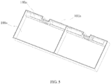
FIG. 5 is a schematic diagram of a lower shell and an output component after being assembled according to an embodiment of the present application; -
FIG. 6 is a schematic diagram of a lower shell and a bare cell after being assembled according to an embodiment of the present application; -
FIG. 7 is a partial sectional view of a battery module according to an embodiment of the present application; -
FIG. 8 is a partial enlarged schematic diagram of section B inFIG. 6 ; and -
FIG. 9 is a schematic diagram showing wrapping of a barrier film on a battery module according to an embodiment of the present application. -
- 1-housing of battery module;
- 10-lower shell;
- 100-lower shell body;
- 100a-accomodating chamber for bare cell;
- 100b-baffle plate;
- 100c-opening;
- 100d-injection hole;
- 100e-installation site for connecting member/first boss;
- 100f- installation site for output component/second boss;
- 100g-output hole;
- 100h-gap;
- 100i-welding boss;
- 102-connecting member;
- 102a-contact surface of connecting member;
- 12-upper cover;
- 120-stop protrusion;
- 14-output component;
- 140- connection plate;
- 140a-contact surface for output component;
- 140b-connecting portion for bare cell;
- 140c-connecting portion for electrode terminal;
- 140d-transition portion;
- 140e-bending portion;
- 142-electrode terminal;
- 142a-welding slot;
- 144-sealing member;
- 146-connecting block;
- 2-bare cell;
- 20-positive electrode tab;
- 22- negative electrode tab;
- 3-barrier film.
- The drawings here are incorporated in the specification and form a part of the specification, which show embodiments of the present application and are used together with the specification to explain the principle of the present application.
- The present application will be further illustrated in detail with reference to specific embodiments and the drawings. The expressions "front", "back", "left", "right", "top" and "bottom" mentioned in the present application are all referring to the placement state of the housing of battery module in the drawings.
- As shown in
FIG. 1 , an embodiment of the present application provides a battery module, including ahousing 1 and a plurality ofbare cells 2. The battery module may further include abarrier film 3 if necessary. Thehousing 1 is configured to accommodate the plurality ofbare cells 2 and constitutes a protection shell of the battery module. As shown inFIG. 2 , thehousing 1 includes alower shell 10, anupper cover 12 and anoutput component 14. - The
lower shell 10 includes alower shell body 100 and a connectingmember 102. Thelower shell body 100 is a main structure of thelower shell 10 and is generally made as a whole of polypropylene (PP) or polybutylene terephthalate (PBT) materials by injection molding. A plurality ofaccommodating chambers 100a for accommodating the plurality ofbare cells 2 are defined in thelower shell body 100. The number of the plurality ofaccommodating chambers 100a may be two or more. InFIG. 2 ,FIG. 3 andFIG. 5 , thelower shell body 100 is separated into twoaccommodating chambers 100a. Theseaccommodating chambers 100a are sequentially arranged along a hypothetical straight line, and each two adjacentaccommodating chambers 100a are separated by abaffle plate 100b therebetween. - Each
accommodating chamber 100a may accommodate only onebare cell 2, or may accommodate two or morebare cells 2. In an embodiment as shown inFIG. 2 , eachaccommodating chamber 100a accommodates twobare cells 2. Eachbare cell 2 generally includes two tabs, and the two tabs have opposite electric polarities, i.e., apositive electrode tab 20 and anegative electrode tab 22. Thesebare cells 2 placed in the sameaccommodating chamber 100a are stacked together with thepositive electrode tabs 20 being connected with each other and with thenegative electrode tab 22 being connected with each other, so as to form a parallel connection circuit. - In order to accommodate the
bare cells 2 and other components, eachaccommodating chamber 100a is provided with anopening 100c at the same side, theaccommodating chamber 100a is generally a cuboid structure of a flat shape and theopening 100c is defined in the largest surface of theaccommodating chamber 100a, so as to facilitate the assembling of thebare cell 2 and other components. Besides, a plurality ofinjection holes 100d is defined in a plurality of positions of thelower shell body 100 corresponding to the plurality ofaccommodating chambers 100a, respectively. The plurality ofinjection holes 100d communicates with the external environment and is configured for injecting electrolyte into the plurality ofaccommodating chambers 100a, respectively. - The connecting
member 102 is configured to connect thebare cells 2 in two adjacentaccommodating chambers 100a in series, i.e., each two adjacentaccommodating chambers 100a are provided with one connectingmember 102 therebetween penetrating through the two adjacentaccommodating chambers 100a. Aninstallation site 100e for installing the connectingmember 102 is provided in eachaccommodating chamber 100a,installation sites 100e in every two adjacentaccommodating chambers 100a are opposite to each other, and the connectingmember 102 is fixed on theinstallation sites 100e. In the embodiment as shown inFIG. 2 , only twoaccommodating chambers 100a and one connectingmember 102 are included. Thenegative electrode tabs 22 of all thebare cells 2 in theaccommodating chamber 100a at the left side are connected with the connectingmember 102, and thepositive electrode tabs 20 of all thebare cells 2 in theaccommodating chamber 100a at the right side are connected with the connectingmember 102, so as to connect all thebare cells 2 in the two adjacentaccommodating chambers 100a in series. - Generally, the
positive electrode tabs 20 and thenegative electrode tabs 22 are made of different materials, for example, thepositive electrode tabs 20 are made of aluminum and thenegative electrode tabs 22 are made of copper. Since the connectingmember 102 is connected with both thepositive electrode tabs 20 and thenegative electrode tabs 22, good connection performance of the connectingmember 102 with both of the two kinds of materials are necessary, thus, the connectingmember 102 in the present embodiment is made of a copper-aluminum composite material. - In addition to that all the
bare cells 2 in the battery module are electrically connected with each other, the battery module further includes a port to be electrically connected with an external device, and the electric energy of thebare cells 2 is transmitted out from the battery module through the port. In an embodiment, aninstallation site 100f for installing theoutput component 14 and anoutput hole 100g are provided in each of the firstaccommodating chamber 100a and the lastaccommodating chamber 100a. For example, in the embodiment including twoaccommodating chambers 100a, the twoaccommodating chambers 100a are the firstaccommodating chamber 100a and the lastaccommodating chamber 100a which are arranged in sequence. In an embodiment as shown inFIG. 3 , twooutput components 14 are provided, and the twooutput components 14 are arranged on theinstallation site 100f for output component in the firstaccommodating chamber 100a and theinstallation site 100f for output component in the lastaccommodating chamber 100a, respectively. Theoutput component 14 at the left side is connected with thepositive electrode tabs 20 of thebare cells 2 in theaccommodating chamber 100a at the left side, and theoutput component 14 at the right side is connected with thenegative electrode tabs 22 of thebare cells 2 in theaccommodating chamber 100a at the right side, so as to connect the twooutput components 14 in series at two ends of the connection circuit of thesebare cells 2. Theoutput component 14 further extends out from theaccommodating chamber 100a through theoutput hole 100g, so as to transmit the electric energy out from theaccommodating chamber 100a. - The
positive electrode tab 20 and thenegative electrode tab 22 of thebare cell 2 are generally classified into side-out type and up-out type, i.e., thepositive electrode tab 20 and thenegative electrode tab 22 are arranged at two sides of thebare cell 2, respectively; or both thepositive electrode tab 20 and thenegative electrode tab 22 are arranged at the top of thebare cell 2. Accordingly, the connectingmember 102 and theoutput component 14 are arranged at corresponding positions in correspondence to a different battery module with a different type of electrode tabs. The battery module with the up-out type electrode tabs is advantageous over the battery module with the side-out type electrode tabs. - As shown in
FIG. 2 andFIG. 6 , thebare cells 2 include up-out type electrode tabs, and all thepositive electrode tabs 20 and thenegative electrode tabs 22 extend from the same side of thebare cells 2, therefore, the electric connection components (i.e., theoutput components 14 and the connecting member 102) can be arranged at the same side of theaccommodating chambers 100a. In an embodiment, the length direction of thebare cells 2 is identical to the arrangement direction of theaccommodating chambers 100a, so that thepositive electrode tabs 20 and thenegative electrode tabs 22 of all thebare cells 2 are oriented toward the same side of thelower shell body 100. Accordingly, theinstallation sites 100f for output component and theinstallation sites 100e for connecting member can also be arranged along the arrangement direction of theaccommodating chambers 100a, so that thelower shell body 100 can have higher structural uniformity. - In order to save internal space of the
accommodating chamber 100a, theinstallation site 100e for connecting member and theinstallation site 100f for output component may be arranged at a side of theaccommodating chamber 100a parallel to the arrangement direction of theaccommodating chambers 100a, and closely attached to an inner wall of theaccommodating chamber 100a. - As shown in
FIG. 5 , when the length direction of thebare cells 2 placed in theaccommodating chambers 100a is identical to the arrangement direction of theaccommodating chambers 100a, the extending direction of thepositive electrode tabs 20 and the extending direction of thenegative electrode tabs 22 are generally identical to the opening direction of theopening 100c, that is, main planes of thepositive electrode tabs 20 and thenegative electrode tabs 22 are oriented toward theopening 100c. Thus, in order to facilitate the connection of the connectingmember 102 with thepositive electrode tabs 20 and thenegative electrode tabs 22, it is preferred that the connectingmember 102 has acontact surface 102a facing theopening 100c, so that the electrode tabs do not need to be bended and thus the spaced occupied will be saved, which can further facilitate welding operation. - It is also preferred that the
output component 14 includes acontact surface 140a for output component, so as to achieve the same effect as thecontact surface 102a. - The connecting
member 102 may be a sheet-like, triangular prism-like, cubic or other more complicated structures, as long as the connectingmember 102 can have onecontact surface 102a, however, the sheet-like structure is simpler and more space-saving as compared with other structures. - In an embodiment, during the forming of the
lower shell body 100, the connectingmember 102 may be pre-embedded at a corresponding position in thelower shell body 100, and then integrated as whole by injection molding and the like, so as to eliminate the installation procedure of the connectingmember 102. - The
bare cell 2 has a certain thickness, and thepositive electrode tab 20 and thenegative electrode tab 22 are generally located close to the middle of the thickness surface of thebare cell 2; if thecontact surface 102a is too close to the edge of thebare cell 2 or directly arranged on the inner wall of theaccommodating chamber 100a facing theopening 100c, the electrode tabs will be too far to be connected with thecontact surface 102a. In view of this, as shown inFIG. 2 , theinstallation site 100e for connecting member may include a first boss (for convenience for referring to the drawings, the first boss is still referred as 100e in the following description), theoutput component 14 is placed on thefirst boss 100e, so that thecontact surface 102a can be closer to the electrode tabs, so as to reduce the connection difficulties. - Similarly, the
installation site 100f for output component may also include a second boss (for convenience for referring to the drawings, the second boss is still referred as 100f in the following description), and thesecond boss 100f plays a similar role as thefirst boss 100e, and thus thecontact surface 140a for output component can be closer to the electrode tabs. - The structure of the
output component 14 is described in details as follows. As shown inFIG. 2 , theoutput component 14 includes aconnection plate 140, anelectrode terminal 142, a sealingmember 144 and a connectingblock 146. As shown inFIG. 4 , theconnection plate 140 includes a connectingportion 140b for bare cell, a connectingportion 140c for electrode terminal, atransition portion 140d and a bendingportion 140e, and the connectingportion 140b for bare cell is electrically connected with the connectingportion 140c for electrode terminal. The connectingportion 140b for bare cell may be a sheet-like structure, a flat surface of the connectingportion 140b for bare cell is attached to thesecond boss 100f and another flat surface of the connectingportion 140b for bare cell serves as thecontact surface 140a for output component. - The connecting
portion 140c for electrode terminal is configured to be connected with theelectrode terminal 142, theelectrode terminal 142 after being connected with the connectingportion 140c for electrode terminal extends out from theaccommodating chamber 100a through theoutput hole 100g, so as to transmit electric energy out of theaccommodating chamber 100a. In order to sufficiently utilize the space, the connectingportion 140c for electrode terminal may also be a sheet-like structure, both the connectingportion 140b for bare cell and the connectingportion 140c for electrode terminal extend along the arrangement direction of theaccommodating chambers 100a, an projection of the connectingportion 140b for bare cell in a plane perpendicular to the arrangement direction is perpendicular to a projection of the connectingportion 140c for electrode terminal in the plane perpendicular to the arrangement direction, that is, the connectingportion 140b for bare cell is oriented toward theopening 100c, and the connectingportion 140c for electrode terminal is oriented toward an inner wall of theaccommodating chamber 100a parallel to the arrangement direction of theaccommodating chambers 100a. Thus, the connection area of the connectingportion 140b for bare cell and the connection area of the connectingportion 140c for electrode terminal can be staggered at 90 degrees, so as to reduce interference risk and realize the sufficient utilization of space. - In order to enhance the connection strength between the connecting
portion 140c for electrode terminal and theelectrode terminal 142, awelding slot 142a may be defined in theelectrode terminal 142, the connectingportion 140c for electrode terminal is inserted in thewelding slot 142a and is welded with theelectrode terminal 142. It is preferred that the outer surface of the connectingportion 140c for electrode terminal is fitted to the inner surface of thewelding slot 142a, so as to improve the welding effect. - The extending direction of the connecting
portion 140b for bare cell is opposite to the extending direction of the connectingportion 140c for electrode terminal, and the projection of the connectingportion 140b for bare cell on a plane perpendicular to the arrangement direction of theaccommodating chambers 100a is perpendicular to the projection of the connectingportion 140c for electrode terminal on the plane perpendicular to the arrangement direction of theaccommodating chambers 100a, thus, if the direct connection between the connectingportion 140b for bare cell and the connectingportion 140c for electrode terminal merely adopts a cross connection or an angular connection, the connection area is small and the connection is insecure and is also inconvenient for processing. Therefore, the connection may be achieved by means of thetransition portion 140d. Thetransition portion 140d is a sheet-like structure, and the extending direction of thetransition portion 140d is perpendicular to the arrangement direction of theaccommodating chambers 100a, i.e., parallel to thebaffle plate 100b. Accordingly, both the connectingportion 140b for bare cell and the connectingportion 140c for electrode terminal are perpendicular to thetransition portion 140d, therefore, both the connectingportion 140b for bare cell and the connectingportion 140c for electrode terminal can be perpendicularly connected with thetransition portion 140d. Or, the connection relation of the connectingportion 140b for bare cell, the connectingportion 140c for electrode terminal and thetransition portion 140d can be achieved by means of an electrical conductive sheet by directly trimming and bending. - In an embodiment, the
output component 14 is not pre-embedded into thelower shell body 100 as theoutput component 14 is required to connect the interior of theaccommodating chamber 100a with the exterior of theaccommodating chamber 100a. However, the embedding-injection molding manner cannot guarantee the sealing performance, therefore, the installation is achieved by an assembling manner. However, the installation by the assembling manner may have a certain deviation. In order to eliminate influence of the deviation on the assembling, acertain gap 100h is defined between thesecond boss 100f and theoutput hole 100g, and a bendingportion 140e is formed between the connectingportion 140b for bare cell and thetransition portion 140d of theadaptor 140. The bendingportion 140e is configured to adjust the angle between the connectingportion 140b for bare cell and thetransition portion 140d and the positions of the connectingportion 140b for bare cell and thetransition portion 140d, so as to eliminate the deviation. Thegap 100h is configured to accommodate the bendingportion 140e. Further, the bendingportion 140e after being accommodated in thegap 100h can also play a role of clamping and thus limiting the movement of the connectingportion 140b for bare cell. - Since the
accommodating chamber 100a is required to be injected with electrolyte, theoutput component 14 shall be sealedly connected with theoutput hole 100g to prevent leakage of the electrolyte. For example, theelectrode terminal 142 seals theoutput hole 100g through a sealing member 144 (e.g., a sealing ring), and a portion of theelectrode terminal 142 extending out of theoutput hole 100g is connected with the connectingblock 146 by welding or riveting. - When the placement and corresponding connection and fixation of the
bare cells 2 and theoutput components 14 are finished, theupper cover 12 covers thelower shell body 100 and is connected with thelower shell 100 by laser welding or other manners, so as to seal all theopenings 100c. As shown inFIGS. 4 ,7 and 8 , in order to improve the sealing performance, awelding boss 100i may be provided on a surface of thelower shell body 100 coordinating with theupper cover 12, and thewelding boss 100i is configured to melt and solidify during welding and then the welding is finished. - In order to prevent overflowing toward the interior of the
accommodating chamber 100a during welding, as shown inFIG. 8 , astop protrusion 120 may be provided at a suitable position on theupper cover 12, thestop protrusion 120 is located at side of theupper cover 12 facing theaccommodating chamber 100a, and thestop protrusion 120 is arranged along the edge of theaccommodating chambers 100a. - The assembling of the battery module is basically finished after the
bare cells 2 are packaged into thehousing 1 of battery module and thelower shell body 100 is welded and sealed with theupper cover 12. During use, thelower shell body 100 and theupper cover 12 define a closed and sealed interior of the battery module. However, the electric vehicles need to be lightweight, and the housings for the electric vehicles also need to be lightweight accordingly. Therefore, it is a developing trend to use a plastic material which is resistant against corrosion of electrolyte as the materials of thelower shell body 100 and theupper cover 12. For examples, suitable choice of the plastic material may include: general plastics such as polyethylene, polypropylene, polyvinyl chloride, polystyrene, ABS (acrylic acid-butadiene-styrene), polymethyl benzoic acid methyl ester and amino plastics; or general engineering plastics such as polyamide, polycarbonate, polyformaldehyde, polyphenylene oxide and thermoplastic polyesters; or special engineering plastics such as polyimide, polyphenylene sulfide, polysulfone, aromatic polyamide, polyarylester, polyphenyl ester, poly (aryl ether ketone), liquid crystalline polymer and fluorine resin. - However, the
lower shell body 100 andupper cover 12 made of plastics have low compactness, and readily age with time, the polymer molecular chains have increasing porosity and increasing permeability of water and oxygen molecules, which influences the inner property of the bare cells, especially the cycle performance of the bare cells. - Therefore, in order to extend service life, a
barrier film 3 may wrap the outer surface of each of thelower shell body 100 and theupper cover 12. Thebarrier film 3 shall be made of a material with water vapor transmission coefficient less than 0.5g/[m2*24h], e.g., aluminum-plastic composite film material, plastics with evaporation plating/deposition composite material on surface or plastic film material with super-high molecular weight. - According to the actual application demands on the materials of the
barrier film 3 and the battery module, there may be one layer ofbarrier film 3, two layers ofbarrier films 3, or more than two layers ofbarrier films 3 wrapping thelower shell body 100 and theupper cover 12. Thebarrier film 3 can be separately arranged according to the position to be wrapped. Thebarrier film 3 can be folded to wrap a plurality of surfaces of both thelower shell body 100 and the upper cover 12 (shown inFIG. 9 ), or be attached to the outer surfaces of thelower shell body 100 and theupper cover 12 by adhering, welding or laminating. - The battery module in the present application is formed by directly using the bare cells, which eliminates the mechanical structures like the lower shell outside the bare cell, therefore, the battery module can have improved energy density.
- The above-mentioned are merely the preferred embodiments of the present application, which are not used to limit the present application. For the person skilled in the art, the present application can have a variety of modifications and changes. Whatever in the spirit and principle of the present application. All modifications, equivalent substitutions and improvement based on the present application shall all be included in the protection scope of the present application.
Claims (15)
- A housing of a battery module, characterized in that, comprising a lower shell, an upper cover and two output components, wherein the lower shell comprises a lower shell body and at least one connecting member;
the lower shell body is separated into a plurality of accommodating chambers for accommodating bare cells, the plurality of accommodating chambers is sequentially arranged along a hypothetical straight line, an opening is defined in each accommodating chamber at a same side, a plurality of injection holes communicating with external environment is defined in the lower shell body, and the plurality of injection holes corresponds to the plurality of accommodating chambers, respectively;
an installation site for connecting member is provided in each accommodating chamber, two installation sites for connecting member in two adjacent accommodation chambers are arranged opposite to each other, every two adjacent accommodating chambers are provided with one connecting member between and penetrating through the every two adjacent accommodating chambers, and the one connecting member is fixed on two installation sites for connecting member in the every two adjacent accommodating chambers, for connecting bare cells in the every two adjacent accommodating chambers in series;
an installation site for output component and an output hole are provided in each of a first one and a last one of the plurality of accommodation chambers; each output component is arranged on one installation site for output component, and extends out from the first one or the last one of the plurality of accommodation chambers through one output hole; the two output components are sealedly connected with two output holes, respectively;
the upper cover is capable of covering and matching with the lower shell body, and sealing all the openings. - The housing of a battery module according to claim 1, characterized in that, the installation site for output component and the installation site for connecting member are arranged along an arrangement direction of the plurality of accommodating chambers.
- The housing of a battery module according to claim 2, characterized in that, the installation site for output component and the installation site for connecting member are arranged at a side of each accommodating chamber parallel to the arrangement direction of the plurality of accommodating chambers.
- The housing of a battery module according to claim 3, characterized in that,
each connecting member comprises a first contact surface oriented toward the opening, and the first contact surface is used for connecting with the bare cells; and/or
each output component comprises a second contact surface oriented toward the opening, and the second contact surface is used for connecting with the bare cells. - The housing of a battery module according to claim 4, characterized in that,
the installation site for connecting member comprises a first boss, and the at least one connecting member is fixed on the first boss, and/or
the installation site for output component comprises a second boss, and each of the two output components is placed on the second boss, correspondingly. - The housing of a battery module according to claim 5, characterized in that, each output component comprises an connection plate, an electrode terminal, a sealing member and a connecting block,
the connection plate comprises a connecting portion for bare cell and a connecting portion for electrode terminal, the connecting portion for bare cell is electrically connected with the connecting portion for electrode terminal, the connecting portion for bare cell is placed on the second boss, and the contact surface for output component is located on the connecting portion for bare cell,
the electrode terminal is connected with the connecting portion for electrode terminal and extends out from a correspondingly accommodation chamber through the output hole, the electrode terminal seals the output hole by the sealing member, and the connecting block is connected with the electrode terminal from an outside of the lower shell body. - The housing of a battery module according to claim 6, characterized in that, both the connecting portion for bare cell and the connecting portion for electrode terminal are sheet-like and extend along the arrangement direction of the plurality of accommodating chambers, and a projection of the connecting portion for bare cell on a plane perpendicular to the arrangement direction of the plurality of accommodating chambers is perpendicular to a projection of the connecting portion for electrode terminal on a plane perpendicular to the arrangement direction of the plurality of accommodating chambers.
- The housing of a battery module according to claim 7, characterized in that, a welding slot is defined in the electrode terminal, and the connecting portion for electrode terminal extends into the welding slot and is welded with the electrode terminal.
- The housing of a battery module according to claim 7, characterized in that, the connection plate further comprises a transition portion, the transition portion is sheet-like and extends along a direction perpendicular to the arrangement direction of the plurality of accommodating chambers, and the connecting portion for bare cell and the connecting portion for electrode terminal are respectively connected with the transition portion.
- The housing of a battery module according to claim 9, characterized in that, a gap is defined between the second boss and the output hole, the connection plate further comprises a bending portion, the connecting portion for bare cell is connected with the transition portion by the bending portion, and the bending portion is capable of being located in the gap when the connecting portion for bare cell is placed on the second boss.
- The housing of a battery module according to any one of claims 1-10, characterized in that, the connecting member is pre-embedded in the lower shell body.
- The housing of a battery module according to any one of claims 1-10, characterized in that, a welding boss is provided on a surface of the lower shell body coordinating with the upper cover.
- The housing of a battery module according to any one of claims 1-10, characterized in that, the upper cover comprises a stop protrusion, the stop protrusion is located at a side of the upper cover facing the plurality of accommodating chambers and is arranged along edges of the plurality of accommodating chambers.
- A battery module, characterized in that, the battery module comprises a plurality of bare cells and the housing of a battery module according to any one of claims 1-13,
each accommodating chamber accommodates at least one bare cell, the at least one bare cell in each accommodation chamber is stacked and in parallel connection with each other,
the at least one bare cell in one accommodation chamber is connected in series with the at least one bare cell in one adjacent accommodation chamber, and the two output components are connected with the at least one bare cell in the first one of the plurality of accommodating chambers and the at least one bare cell in the last one of the plurality of accommodating chambers, respectively. - The battery module according to claim 14, characterized in that, the battery module further comprises a barrier film, both the lower shell body and the upper cover are made of plastics, and the barrier film wraps a surface of the lower shell body and a surface of the upper cover.
Applications Claiming Priority (1)
| Application Number | Priority Date | Filing Date | Title |
|---|---|---|---|
| CN201611225113.7A CN106505169B (en) | 2016-12-27 | 2016-12-27 | Battery module housing structure and battery module |
Publications (2)
| Publication Number | Publication Date |
|---|---|
| EP3343665A1 true EP3343665A1 (en) | 2018-07-04 |
| EP3343665B1 EP3343665B1 (en) | 2020-06-10 |
Family
ID=58334389
Family Applications (1)
| Application Number | Title | Priority Date | Filing Date |
|---|---|---|---|
| EP17208129.1A Active EP3343665B1 (en) | 2016-12-27 | 2017-12-18 | Housing of battery module and battery module |
Country Status (4)
| Country | Link |
|---|---|
| US (1) | US10629871B2 (en) |
| EP (1) | EP3343665B1 (en) |
| CN (1) | CN106505169B (en) |
| PT (1) | PT3343665T (en) |
Cited By (3)
| Publication number | Priority date | Publication date | Assignee | Title |
|---|---|---|---|---|
| EP3557647A1 (en) * | 2018-04-20 | 2019-10-23 | Contemporary Amperex Technology Co., Limited | Secondary battery and battery module |
| CN112259858A (en) * | 2020-10-13 | 2021-01-22 | 合肥国轩高科动力能源有限公司 | Lithium ion battery |
| EP3726626A4 (en) * | 2019-01-07 | 2021-04-14 | Contemporary Amperex Technology Co., Limited | AUXILIARY BATTERY AND BATTERY MODULE |
Families Citing this family (23)
| Publication number | Priority date | Publication date | Assignee | Title |
|---|---|---|---|---|
| CN107808939A (en) * | 2017-09-26 | 2018-03-16 | 努比亚技术有限公司 | A kind of end cell structure and mobile terminal |
| KR102248228B1 (en) | 2017-09-26 | 2021-05-03 | 주식회사 엘지화학 | Battery module housing by applying Electromagnetic pulse technology and Method for manufacturing the same |
| CN109994662A (en) * | 2017-12-29 | 2019-07-09 | 上汽通用五菱汽车股份有限公司 | A power battery box for a hybrid vehicle |
| CN108428852B (en) * | 2018-01-12 | 2024-02-09 | 宁德时代新能源科技股份有限公司 | Secondary battery and automobile |
| CN108336273B (en) * | 2018-04-10 | 2023-10-13 | 苏州鸿钜金属制品有限公司 | Power battery pack for vehicle |
| DE102018119051A1 (en) | 2018-08-06 | 2020-02-06 | Webasto SE | Battery case, battery system and assembly method for a battery system |
| CN109360912A (en) * | 2018-10-19 | 2019-02-19 | 珠海格力电器股份有限公司 | Battery module and power battery thereof |
| CN110518174B (en) * | 2019-10-23 | 2020-03-20 | 比亚迪股份有限公司 | Battery, battery module, battery pack and electric vehicle |
| CN112838298B (en) * | 2019-11-22 | 2021-11-12 | 比亚迪股份有限公司 | Batteries, battery modules, battery packs and electric vehicles |
| CN112952240B (en) * | 2019-11-22 | 2022-03-18 | 比亚迪股份有限公司 | Battery, battery module, battery pack and automobile |
| CN112838331B (en) * | 2019-11-22 | 2022-01-07 | 比亚迪股份有限公司 | Battery, battery module, battery pack and electric vehicle |
| CN112838325B (en) | 2019-11-22 | 2021-11-12 | 比亚迪股份有限公司 | A battery, battery module, battery pack and electric vehicle |
| CN113782879A (en) * | 2020-05-22 | 2021-12-10 | 比亚迪股份有限公司 | Battery packs and electric vehicles |
| CN112234280A (en) * | 2020-09-30 | 2021-01-15 | 荣盛盟固利新能源科技有限公司 | battery system |
| CN114914617A (en) * | 2021-02-09 | 2022-08-16 | 荣耀终端有限公司 | Battery and electronic equipment |
| CN113140851A (en) * | 2021-03-23 | 2021-07-20 | 荣盛盟固利新能源科技有限公司 | Lithium ion battery module |
| CN114375522A (en) * | 2021-03-30 | 2022-04-19 | 宁德新能源科技有限公司 | Battery pack |
| CN116508196A (en) * | 2021-11-11 | 2023-07-28 | 宁德时代新能源科技股份有限公司 | Battery cell, manufacturing method and system thereof, battery, and electrical device |
| CN114566694A (en) * | 2022-03-04 | 2022-05-31 | 上海兰钧新能源科技有限公司 | Battery assembly structure and battery assembly method |
| WO2024082095A1 (en) * | 2022-10-17 | 2024-04-25 | 宁德时代新能源科技股份有限公司 | Battery cell, battery and electrical device |
| CN218677425U (en) * | 2022-11-15 | 2023-03-21 | 珠海冠宇电池股份有限公司 | Battery and electronic equipment |
| CN220172269U (en) * | 2022-12-19 | 2023-12-12 | 珠海冠宇电源有限公司 | Battery pack box and battery pack |
| CN118173853B (en) * | 2024-04-02 | 2025-06-27 | 蜂巢能源科技股份有限公司 | Battery module assembly method |
Citations (3)
| Publication number | Priority date | Publication date | Assignee | Title |
|---|---|---|---|---|
| US20060166087A1 (en) * | 2005-01-25 | 2006-07-27 | Toyota Jidosha Kabushiki Kaisha | Secondary battery |
| US20080014499A1 (en) * | 2004-06-02 | 2008-01-17 | Sylva Industries Limited | Prismatic Battery With Novel Intercell Connection |
| US20160248052A1 (en) * | 2015-02-23 | 2016-08-25 | Showa Denko Packaging Co., Ltd. | Power storage device and production method thereof |
Family Cites Families (5)
| Publication number | Priority date | Publication date | Assignee | Title |
|---|---|---|---|---|
| JP4642179B2 (en) * | 1999-10-08 | 2011-03-02 | パナソニック株式会社 | Collective secondary battery |
| CN1254871C (en) * | 2001-08-06 | 2006-05-03 | 松下电器产业株式会社 | Rectangular sealed battery |
| CN203326064U (en) * | 2013-07-11 | 2013-12-04 | 安徽江淮汽车股份有限公司 | Battery module and electric vehicle |
| CN204927359U (en) * | 2015-09-24 | 2015-12-30 | 宁德时代新能源科技有限公司 | Insulation shell structure and adopt lithium ion power batteries of this insulation shell structure |
| CN206271794U (en) * | 2016-12-27 | 2017-06-20 | 宁德时代新能源科技股份有限公司 | Battery modules shell structure and battery modules |
-
2016
- 2016-12-27 CN CN201611225113.7A patent/CN106505169B/en active Active
-
2017
- 2017-12-13 US US15/839,949 patent/US10629871B2/en active Active
- 2017-12-18 PT PT172081291T patent/PT3343665T/en unknown
- 2017-12-18 EP EP17208129.1A patent/EP3343665B1/en active Active
Patent Citations (3)
| Publication number | Priority date | Publication date | Assignee | Title |
|---|---|---|---|---|
| US20080014499A1 (en) * | 2004-06-02 | 2008-01-17 | Sylva Industries Limited | Prismatic Battery With Novel Intercell Connection |
| US20060166087A1 (en) * | 2005-01-25 | 2006-07-27 | Toyota Jidosha Kabushiki Kaisha | Secondary battery |
| US20160248052A1 (en) * | 2015-02-23 | 2016-08-25 | Showa Denko Packaging Co., Ltd. | Power storage device and production method thereof |
Cited By (6)
| Publication number | Priority date | Publication date | Assignee | Title |
|---|---|---|---|---|
| EP3557647A1 (en) * | 2018-04-20 | 2019-10-23 | Contemporary Amperex Technology Co., Limited | Secondary battery and battery module |
| US10818882B2 (en) | 2018-04-20 | 2020-10-27 | Contemporary Amperex Technology Co., Limited | Secondary battery and battery module |
| EP3726626A4 (en) * | 2019-01-07 | 2021-04-14 | Contemporary Amperex Technology Co., Limited | AUXILIARY BATTERY AND BATTERY MODULE |
| US11088398B2 (en) | 2019-01-07 | 2021-08-10 | Contemporary Amperex Technology Co., Limited | Secondary battery and battery module |
| CN112259858A (en) * | 2020-10-13 | 2021-01-22 | 合肥国轩高科动力能源有限公司 | Lithium ion battery |
| CN112259858B (en) * | 2020-10-13 | 2022-05-13 | 合肥国轩高科动力能源有限公司 | Lithium ion battery |
Also Published As
| Publication number | Publication date |
|---|---|
| CN106505169A (en) | 2017-03-15 |
| PT3343665T (en) | 2020-08-26 |
| US10629871B2 (en) | 2020-04-21 |
| US20180183023A1 (en) | 2018-06-28 |
| CN106505169B (en) | 2024-09-24 |
| EP3343665B1 (en) | 2020-06-10 |
Similar Documents
| Publication | Publication Date | Title |
|---|---|---|
| EP3343665B1 (en) | Housing of battery module and battery module | |
| CN206271794U (en) | Battery modules shell structure and battery modules | |
| US10608219B2 (en) | Integrated cartridge and battery pack comprising same | |
| US10615397B2 (en) | Battery design with bussing integral to battery assembly | |
| KR20170047687A (en) | Cartridge for secondary battery and battery module including the same | |
| KR20170017514A (en) | Battery pack | |
| WO2014027783A1 (en) | Battery module comprising venting guidance portion | |
| WO2014123329A1 (en) | Battery cell including stepped structure | |
| CN114424391A (en) | Battery pack with improved vibration resistance | |
| US20190173065A1 (en) | Prismatic-Pouch Hybrid Battery Module | |
| JP5206711B2 (en) | Power storage module and module frame | |
| KR20170095136A (en) | Intergrated Cartridge for battery cell and Battery Pack having the same | |
| WO2024157601A1 (en) | Electric power storage module | |
| JP7506186B2 (en) | Secondary battery module, secondary battery pack including the same, and automobile | |
| JP7605204B2 (en) | Energy storage facilities | |
| WO2021024728A1 (en) | Power storage device | |
| JP4784067B2 (en) | Power storage module | |
| US20250350010A1 (en) | Pouch-Type Secondary Battery Cell | |
| KR20160096485A (en) | Compact secondary battery module | |
| JP6842097B1 (en) | Power storage module | |
| WO2021166624A1 (en) | Electrical storage device | |
| JP7826759B2 (en) | Power storage device | |
| CN120457590A (en) | Battery module and battery pack including the same | |
| JP2019145245A (en) | Battery device | |
| JP2024030630A (en) | Power storage device |
Legal Events
| Date | Code | Title | Description |
|---|---|---|---|
| PUAI | Public reference made under article 153(3) epc to a published international application that has entered the european phase |
Free format text: ORIGINAL CODE: 0009012 |
|
| STAA | Information on the status of an ep patent application or granted ep patent |
Free format text: STATUS: REQUEST FOR EXAMINATION WAS MADE |
|
| 17P | Request for examination filed |
Effective date: 20171218 |
|
| AK | Designated contracting states |
Kind code of ref document: A1 Designated state(s): AL AT BE BG CH CY CZ DE DK EE ES FI FR GB GR HR HU IE IS IT LI LT LU LV MC MK MT NL NO PL PT RO RS SE SI SK SM TR |
|
| AX | Request for extension of the european patent |
Extension state: BA ME |
|
| STAA | Information on the status of an ep patent application or granted ep patent |
Free format text: STATUS: EXAMINATION IS IN PROGRESS |
|
| 17Q | First examination report despatched |
Effective date: 20190925 |
|
| REG | Reference to a national code |
Ref country code: DE Ref legal event code: R079 Ref document number: 602017017935 Country of ref document: DE Free format text: PREVIOUS MAIN CLASS: H01M0002020000 Ipc: H01M0002100000 |
|
| GRAP | Despatch of communication of intention to grant a patent |
Free format text: ORIGINAL CODE: EPIDOSNIGR1 |
|
| STAA | Information on the status of an ep patent application or granted ep patent |
Free format text: STATUS: GRANT OF PATENT IS INTENDED |
|
| RIC1 | Information provided on ipc code assigned before grant |
Ipc: H01M 2/10 20060101AFI20200220BHEP Ipc: H01M 2/36 20060101ALN20200220BHEP Ipc: H01M 2/30 20060101ALI20200220BHEP Ipc: H01M 2/20 20060101ALI20200220BHEP |
|
| INTG | Intention to grant announced |
Effective date: 20200319 |
|
| GRAS | Grant fee paid |
Free format text: ORIGINAL CODE: EPIDOSNIGR3 |
|
| GRAA | (expected) grant |
Free format text: ORIGINAL CODE: 0009210 |
|
| STAA | Information on the status of an ep patent application or granted ep patent |
Free format text: STATUS: THE PATENT HAS BEEN GRANTED |
|
| AK | Designated contracting states |
Kind code of ref document: B1 Designated state(s): AL AT BE BG CH CY CZ DE DK EE ES FI FR GB GR HR HU IE IS IT LI LT LU LV MC MK MT NL NO PL PT RO RS SE SI SK SM TR |
|
| REG | Reference to a national code |
Ref country code: GB Ref legal event code: FG4D |
|
| REG | Reference to a national code |
Ref country code: CH Ref legal event code: EP Ref country code: AT Ref legal event code: REF Ref document number: 1279892 Country of ref document: AT Kind code of ref document: T Effective date: 20200615 |
|
| REG | Reference to a national code |
Ref country code: DE Ref legal event code: R096 Ref document number: 602017017935 Country of ref document: DE |
|
| REG | Reference to a national code |
Ref country code: IE Ref legal event code: FG4D |
|
| REG | Reference to a national code |
Ref country code: SE Ref legal event code: TRGR |
|
| REG | Reference to a national code |
Ref country code: PT Ref legal event code: SC4A Ref document number: 3343665 Country of ref document: PT Date of ref document: 20200826 Kind code of ref document: T Free format text: AVAILABILITY OF NATIONAL TRANSLATION Effective date: 20200813 |
|
| REG | Reference to a national code |
Ref country code: LT Ref legal event code: MG4D |
|
| PG25 | Lapsed in a contracting state [announced via postgrant information from national office to epo] |
Ref country code: LT Free format text: LAPSE BECAUSE OF FAILURE TO SUBMIT A TRANSLATION OF THE DESCRIPTION OR TO PAY THE FEE WITHIN THE PRESCRIBED TIME-LIMIT Effective date: 20200610 Ref country code: FI Free format text: LAPSE BECAUSE OF FAILURE TO SUBMIT A TRANSLATION OF THE DESCRIPTION OR TO PAY THE FEE WITHIN THE PRESCRIBED TIME-LIMIT Effective date: 20200610 Ref country code: GR Free format text: LAPSE BECAUSE OF FAILURE TO SUBMIT A TRANSLATION OF THE DESCRIPTION OR TO PAY THE FEE WITHIN THE PRESCRIBED TIME-LIMIT Effective date: 20200911 Ref country code: NO Free format text: LAPSE BECAUSE OF FAILURE TO SUBMIT A TRANSLATION OF THE DESCRIPTION OR TO PAY THE FEE WITHIN THE PRESCRIBED TIME-LIMIT Effective date: 20200910 |
|
| REG | Reference to a national code |
Ref country code: NL Ref legal event code: MP Effective date: 20200610 |
|
| REG | Reference to a national code |
Ref country code: DE Ref legal event code: R079 Ref document number: 602017017935 Country of ref document: DE Free format text: PREVIOUS MAIN CLASS: H01M0002100000 Ipc: H01M0050200000 |
|
| PG25 | Lapsed in a contracting state [announced via postgrant information from national office to epo] |
Ref country code: BG Free format text: LAPSE BECAUSE OF FAILURE TO SUBMIT A TRANSLATION OF THE DESCRIPTION OR TO PAY THE FEE WITHIN THE PRESCRIBED TIME-LIMIT Effective date: 20200910 Ref country code: RS Free format text: LAPSE BECAUSE OF FAILURE TO SUBMIT A TRANSLATION OF THE DESCRIPTION OR TO PAY THE FEE WITHIN THE PRESCRIBED TIME-LIMIT Effective date: 20200610 Ref country code: HR Free format text: LAPSE BECAUSE OF FAILURE TO SUBMIT A TRANSLATION OF THE DESCRIPTION OR TO PAY THE FEE WITHIN THE PRESCRIBED TIME-LIMIT Effective date: 20200610 Ref country code: LV Free format text: LAPSE BECAUSE OF FAILURE TO SUBMIT A TRANSLATION OF THE DESCRIPTION OR TO PAY THE FEE WITHIN THE PRESCRIBED TIME-LIMIT Effective date: 20200610 |
|
| REG | Reference to a national code |
Ref country code: AT Ref legal event code: MK05 Ref document number: 1279892 Country of ref document: AT Kind code of ref document: T Effective date: 20200610 |
|
| PG25 | Lapsed in a contracting state [announced via postgrant information from national office to epo] |
Ref country code: AL Free format text: LAPSE BECAUSE OF FAILURE TO SUBMIT A TRANSLATION OF THE DESCRIPTION OR TO PAY THE FEE WITHIN THE PRESCRIBED TIME-LIMIT Effective date: 20200610 Ref country code: NL Free format text: LAPSE BECAUSE OF FAILURE TO SUBMIT A TRANSLATION OF THE DESCRIPTION OR TO PAY THE FEE WITHIN THE PRESCRIBED TIME-LIMIT Effective date: 20200610 |
|
| PG25 | Lapsed in a contracting state [announced via postgrant information from national office to epo] |
Ref country code: EE Free format text: LAPSE BECAUSE OF FAILURE TO SUBMIT A TRANSLATION OF THE DESCRIPTION OR TO PAY THE FEE WITHIN THE PRESCRIBED TIME-LIMIT Effective date: 20200610 Ref country code: AT Free format text: LAPSE BECAUSE OF FAILURE TO SUBMIT A TRANSLATION OF THE DESCRIPTION OR TO PAY THE FEE WITHIN THE PRESCRIBED TIME-LIMIT Effective date: 20200610 Ref country code: SM Free format text: LAPSE BECAUSE OF FAILURE TO SUBMIT A TRANSLATION OF THE DESCRIPTION OR TO PAY THE FEE WITHIN THE PRESCRIBED TIME-LIMIT Effective date: 20200610 Ref country code: ES Free format text: LAPSE BECAUSE OF FAILURE TO SUBMIT A TRANSLATION OF THE DESCRIPTION OR TO PAY THE FEE WITHIN THE PRESCRIBED TIME-LIMIT Effective date: 20200610 Ref country code: CZ Free format text: LAPSE BECAUSE OF FAILURE TO SUBMIT A TRANSLATION OF THE DESCRIPTION OR TO PAY THE FEE WITHIN THE PRESCRIBED TIME-LIMIT Effective date: 20200610 Ref country code: RO Free format text: LAPSE BECAUSE OF FAILURE TO SUBMIT A TRANSLATION OF THE DESCRIPTION OR TO PAY THE FEE WITHIN THE PRESCRIBED TIME-LIMIT Effective date: 20200610 Ref country code: IT Free format text: LAPSE BECAUSE OF FAILURE TO SUBMIT A TRANSLATION OF THE DESCRIPTION OR TO PAY THE FEE WITHIN THE PRESCRIBED TIME-LIMIT Effective date: 20200610 |
|
| PG25 | Lapsed in a contracting state [announced via postgrant information from national office to epo] |
Ref country code: PL Free format text: LAPSE BECAUSE OF FAILURE TO SUBMIT A TRANSLATION OF THE DESCRIPTION OR TO PAY THE FEE WITHIN THE PRESCRIBED TIME-LIMIT Effective date: 20200610 Ref country code: SK Free format text: LAPSE BECAUSE OF FAILURE TO SUBMIT A TRANSLATION OF THE DESCRIPTION OR TO PAY THE FEE WITHIN THE PRESCRIBED TIME-LIMIT Effective date: 20200610 Ref country code: IS Free format text: LAPSE BECAUSE OF FAILURE TO SUBMIT A TRANSLATION OF THE DESCRIPTION OR TO PAY THE FEE WITHIN THE PRESCRIBED TIME-LIMIT Effective date: 20201010 |
|
| REG | Reference to a national code |
Ref country code: DE Ref legal event code: R097 Ref document number: 602017017935 Country of ref document: DE |
|
| PLBE | No opposition filed within time limit |
Free format text: ORIGINAL CODE: 0009261 |
|
| STAA | Information on the status of an ep patent application or granted ep patent |
Free format text: STATUS: NO OPPOSITION FILED WITHIN TIME LIMIT |
|
| PG25 | Lapsed in a contracting state [announced via postgrant information from national office to epo] |
Ref country code: DK Free format text: LAPSE BECAUSE OF FAILURE TO SUBMIT A TRANSLATION OF THE DESCRIPTION OR TO PAY THE FEE WITHIN THE PRESCRIBED TIME-LIMIT Effective date: 20200610 |
|
| 26N | No opposition filed |
Effective date: 20210311 |
|
| PG25 | Lapsed in a contracting state [announced via postgrant information from national office to epo] |
Ref country code: SI Free format text: LAPSE BECAUSE OF FAILURE TO SUBMIT A TRANSLATION OF THE DESCRIPTION OR TO PAY THE FEE WITHIN THE PRESCRIBED TIME-LIMIT Effective date: 20200610 |
|
| REG | Reference to a national code |
Ref country code: CH Ref legal event code: PL |
|
| PG25 | Lapsed in a contracting state [announced via postgrant information from national office to epo] |
Ref country code: MC Free format text: LAPSE BECAUSE OF FAILURE TO SUBMIT A TRANSLATION OF THE DESCRIPTION OR TO PAY THE FEE WITHIN THE PRESCRIBED TIME-LIMIT Effective date: 20200610 |
|
| PG25 | Lapsed in a contracting state [announced via postgrant information from national office to epo] |
Ref country code: LU Free format text: LAPSE BECAUSE OF NON-PAYMENT OF DUE FEES Effective date: 20201218 Ref country code: IE Free format text: LAPSE BECAUSE OF NON-PAYMENT OF DUE FEES Effective date: 20201218 |
|
| PG25 | Lapsed in a contracting state [announced via postgrant information from national office to epo] |
Ref country code: LI Free format text: LAPSE BECAUSE OF NON-PAYMENT OF DUE FEES Effective date: 20201231 Ref country code: CH Free format text: LAPSE BECAUSE OF NON-PAYMENT OF DUE FEES Effective date: 20201231 |
|
| PG25 | Lapsed in a contracting state [announced via postgrant information from national office to epo] |
Ref country code: TR Free format text: LAPSE BECAUSE OF FAILURE TO SUBMIT A TRANSLATION OF THE DESCRIPTION OR TO PAY THE FEE WITHIN THE PRESCRIBED TIME-LIMIT Effective date: 20200610 Ref country code: MT Free format text: LAPSE BECAUSE OF FAILURE TO SUBMIT A TRANSLATION OF THE DESCRIPTION OR TO PAY THE FEE WITHIN THE PRESCRIBED TIME-LIMIT Effective date: 20200610 Ref country code: CY Free format text: LAPSE BECAUSE OF FAILURE TO SUBMIT A TRANSLATION OF THE DESCRIPTION OR TO PAY THE FEE WITHIN THE PRESCRIBED TIME-LIMIT Effective date: 20200610 |
|
| PG25 | Lapsed in a contracting state [announced via postgrant information from national office to epo] |
Ref country code: MK Free format text: LAPSE BECAUSE OF FAILURE TO SUBMIT A TRANSLATION OF THE DESCRIPTION OR TO PAY THE FEE WITHIN THE PRESCRIBED TIME-LIMIT Effective date: 20200610 |
|
| P01 | Opt-out of the competence of the unified patent court (upc) registered |
Effective date: 20230516 |
|
| REG | Reference to a national code |
Ref country code: DE Ref legal event code: R081 Ref document number: 602017017935 Country of ref document: DE Owner name: CONTEMPORARY AMPEREX TECHNOLOGY (HONG KONG) LT, HK Free format text: FORMER OWNER: CONTEMPORARY AMPEREX TECHNOLOGY CO., LTD., NINGDE CITY, FUJIAN, CN |
|
| REG | Reference to a national code |
Ref country code: GB Ref legal event code: 732E Free format text: REGISTERED BETWEEN 20240801 AND 20240807 |
|
| REG | Reference to a national code |
Ref country code: BE Ref legal event code: PD Owner name: CONTEMPORARY AMPEREX TECHNOLOGY (HONG KONG) LIMITED; CN Free format text: DETAILS ASSIGNMENT: CHANGE OF OWNER(S), ASSIGNMENT; FORMER OWNER NAME: CONTEMPORARY AMPEREX TECHNOLOGY CO., LIMITED Effective date: 20240807 |
|
| PGFP | Annual fee paid to national office [announced via postgrant information from national office to epo] |
Ref country code: PT Payment date: 20251202 Year of fee payment: 9 |
|
| PGFP | Annual fee paid to national office [announced via postgrant information from national office to epo] |
Ref country code: DE Payment date: 20250930 Year of fee payment: 9 |
|
| PGFP | Annual fee paid to national office [announced via postgrant information from national office to epo] |
Ref country code: GB Payment date: 20251001 Year of fee payment: 9 |
|
| PGFP | Annual fee paid to national office [announced via postgrant information from national office to epo] |
Ref country code: FR Payment date: 20251008 Year of fee payment: 9 |
|
| PGFP | Annual fee paid to national office [announced via postgrant information from national office to epo] |
Ref country code: BE Payment date: 20251003 Year of fee payment: 9 |
|
| PGFP | Annual fee paid to national office [announced via postgrant information from national office to epo] |
Ref country code: SE Payment date: 20251001 Year of fee payment: 9 |