EP3343344A1 - System and method for storing data in data storage unit of virtual storage area network - Google Patents
System and method for storing data in data storage unit of virtual storage area network Download PDFInfo
- Publication number
- EP3343344A1 EP3343344A1 EP17163901.6A EP17163901A EP3343344A1 EP 3343344 A1 EP3343344 A1 EP 3343344A1 EP 17163901 A EP17163901 A EP 17163901A EP 3343344 A1 EP3343344 A1 EP 3343344A1
- Authority
- EP
- European Patent Office
- Prior art keywords
- node
- data
- storage unit
- data storage
- storing
- Prior art date
- Legal status (The legal status is an assumption and is not a legal conclusion. Google has not performed a legal analysis and makes no representation as to the accuracy of the status listed.)
- Withdrawn
Links
Images


Classifications
-
- H—ELECTRICITY
- H04—ELECTRIC COMMUNICATION TECHNIQUE
- H04L—TRANSMISSION OF DIGITAL INFORMATION, e.g. TELEGRAPHIC COMMUNICATION
- H04L67/00—Network arrangements or protocols for supporting network services or applications
- H04L67/01—Protocols
- H04L67/10—Protocols in which an application is distributed across nodes in the network
- H04L67/1097—Protocols in which an application is distributed across nodes in the network for distributed storage of data in networks, e.g. transport arrangements for network file system [NFS], storage area networks [SAN] or network attached storage [NAS]
-
- G—PHYSICS
- G06—COMPUTING OR CALCULATING; COUNTING
- G06F—ELECTRIC DIGITAL DATA PROCESSING
- G06F3/00—Input arrangements for transferring data to be processed into a form capable of being handled by the computer; Output arrangements for transferring data from processing unit to output unit, e.g. interface arrangements
- G06F3/06—Digital input from, or digital output to, record carriers, e.g. RAID, emulated record carriers or networked record carriers
- G06F3/0601—Interfaces specially adapted for storage systems
- G06F3/0602—Interfaces specially adapted for storage systems specifically adapted to achieve a particular effect
- G06F3/0604—Improving or facilitating administration, e.g. storage management
-
- G—PHYSICS
- G06—COMPUTING OR CALCULATING; COUNTING
- G06F—ELECTRIC DIGITAL DATA PROCESSING
- G06F3/00—Input arrangements for transferring data to be processed into a form capable of being handled by the computer; Output arrangements for transferring data from processing unit to output unit, e.g. interface arrangements
- G06F3/06—Digital input from, or digital output to, record carriers, e.g. RAID, emulated record carriers or networked record carriers
- G06F3/0601—Interfaces specially adapted for storage systems
- G06F3/0628—Interfaces specially adapted for storage systems making use of a particular technique
- G06F3/0629—Configuration or reconfiguration of storage systems
- G06F3/0631—Configuration or reconfiguration of storage systems by allocating resources to storage systems
-
- G—PHYSICS
- G06—COMPUTING OR CALCULATING; COUNTING
- G06F—ELECTRIC DIGITAL DATA PROCESSING
- G06F3/00—Input arrangements for transferring data to be processed into a form capable of being handled by the computer; Output arrangements for transferring data from processing unit to output unit, e.g. interface arrangements
- G06F3/06—Digital input from, or digital output to, record carriers, e.g. RAID, emulated record carriers or networked record carriers
- G06F3/0601—Interfaces specially adapted for storage systems
- G06F3/0628—Interfaces specially adapted for storage systems making use of a particular technique
- G06F3/0629—Configuration or reconfiguration of storage systems
- G06F3/0635—Configuration or reconfiguration of storage systems by changing the path, e.g. traffic rerouting, path reconfiguration
-
- G—PHYSICS
- G06—COMPUTING OR CALCULATING; COUNTING
- G06F—ELECTRIC DIGITAL DATA PROCESSING
- G06F3/00—Input arrangements for transferring data to be processed into a form capable of being handled by the computer; Output arrangements for transferring data from processing unit to output unit, e.g. interface arrangements
- G06F3/06—Digital input from, or digital output to, record carriers, e.g. RAID, emulated record carriers or networked record carriers
- G06F3/0601—Interfaces specially adapted for storage systems
- G06F3/0668—Interfaces specially adapted for storage systems adopting a particular infrastructure
- G06F3/067—Distributed or networked storage systems, e.g. storage area networks [SAN], network attached storage [NAS]
-
- H—ELECTRICITY
- H04—ELECTRIC COMMUNICATION TECHNIQUE
- H04L—TRANSMISSION OF DIGITAL INFORMATION, e.g. TELEGRAPHIC COMMUNICATION
- H04L43/00—Arrangements for monitoring or testing data switching networks
- H04L43/16—Threshold monitoring
Definitions
- the present disclosure relates to data storage in a Virtual Storage Area Network (VSAN). More particularly, but not exclusively, the present disclosure relates to effective utilization of data storage units for storing data in the VSAN.
- VSAN Virtual Storage Area Network
- a storage area network is a dedicated high-speed network for interconnecting and presenting a shared pool of storage devices to multiple servers.
- SAN is primarily used to enhance performance of the storage devices as they appear as a single locally attached device to the servers, where the servers are centrally managed.
- Virtual Storage Area Network is a logical partition in the SAN.
- the VSAN allows data traffic of the servers to be isolated within specific portions of SAN so that system of storage devices is scaled out and is easy to configure.
- the main objective of the VSAN is the easy management of subscribers which can be added or relocated without the need for changing the physical layout of storage.
- Another objective of the VSAN is to provide data redundancy which minimizes the risk of data loss.
- a conventional VSAN storage array includes a brick as a basic building block.
- the brick of the VSAN architecture comprises two storage controllers for receiving Input/Output (I/O) request from host machines connected to the bricks.
- the brick further comprises a Disk Array Enclosure (DAE) for holding multiple Solid State Drives (SSD) for storing data, and backup units.
- DAE Disk Array Enclosure
- Each storage controller has multi-core Central Processing Units (CPUs) for processing I/O tasks.
- the bricks may be clustered together to increase performance and capacity of the system.
- a cluster in VSAN may include two or more bricks. When storage space in a brick of the cluster is utilized up to a threshold, an alert is sent to a user to scale out the system by including additional bricks in the system.
- the threshold may be 90% of total storage available in the brick.
- the user has to manually instruct the system for including additional bricks in the system.
- inclusion of additional bricks in the system may cost substantial amount of money.
- a new I/O request has to wait in a process queue to be processed, hence increasing latency to process the request.
- the existing VSAN architecture only alerts the user, and does not provide automatic inclusion of bricks to the VSAN network, i.e. in the existing architecture, there does not exist a mechanism to route the data to different a secondary data storage unit when primary data storage unit is overloaded. Therefore, the bricks of the VSAN network is not fully utilized. Also, in the conventional VSAN architecture, an I/O request cannot be passed to different bricks of the VSAN. Thus, processing load of a brick is not efficiently managed.
- the present disclosure presents a method for storing data in a data storage unit of a Virtual Storage Area Network (VSAN).
- the method comprises receiving, by a server management system, a request message for storing data, from an array controller of a first node among a plurality of nodes of a Virtual Storage Area Network (VSAN) cluster, where each of the plurality of nodes comprises a pair of array controllers and a data storage unit, identifying a second node from the plurality of nodes, for storing the data in a data storage unit of the second node and routing the data to an array controller of the second node, for storing the data in the data storage unit, for effectively utilizing the data storage unit of the VSAN network.
- VSAN Virtual Storage Area Network
- the present disclosure presents a system for storing data in a data storage unit of a Virtual Storage Area Network (VSAN).
- the system comprises a processor and a memory.
- the processor is configured to receive a request message for storing data, from an array controller of a first node among a plurality of nodes of a Virtual Storage Area Network (VSAN) cluster, wherein each of the plurality of nodes comprises a pair of array controllers and a data storage unit, identify a second node from the plurality of nodes, for storing the data in a data storage unit of the second node and route the data to an array controller of the second node, for storing the data in the data storage unit, for effectively utilizing the data storage unit of the VSAN network.
- VSAN Virtual Storage Area Network
- the present disclosure discloses a server management system for storing data in a data storage unit of a Virtual Storage Area Network (VSAN).
- the server management system receives a request message from a first node of a VSAN, for storing data, when a data storage unit of the first node cannot accommodate the data. Then, the server management system identifies a second node among plurality of nodes of the VSAN for storing the data in data storage unit of the second node.
- the present disclosure provides a system for utilizing data storage unit of the VSAN.
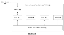
- FIG. 1 shows a VSAN 100 architecture for storing data in a data storage unit in accordance with some embodiments of the present disclosure.
- the VSAN 100 comprises node 101A, node 101B, node 101C, ..., node 101N, a server management system 102 and a switch 103.
- the VSAN 100 is connected to a host device 104.
- a host device 104 For illustration, only one user device 104 is shown in Figure 1 . However, plurality of user devices can be connected to a single node.
- the node 101A, node 101B, node 101c, ..., node 101N may be collectively represented as plurality of nodes 101.
- the term plurality of nodes 101 is used throughout this disclosure to represent the collective representation of node 101A, node 101B, node 101C, ..., node 101N.
- Each of the plurality of nodes 101 is connected to the server management system 102, either by wired interface or wireless interface.
- each of the plurality of nodes 101 may be a server.
- each of the plurality of nodes 101 may be connected to a host device 104.
- the switch 103 receives one or more Input/Output (I/O) request messages from the host device 104.
- the one or more I/O request messages may comprise instructions for storing data, along with data to be stored.
- the one or more I/O request message may further comprise address for storing the data.
- the switch 103 forwards the one or more I/O request messages to corresponding node among the plurality of nodes 101 based on the address.
- the switch 103 is connected to the node 101A in Figure 1 .
- the switch 103 will be connected to one or more nodes.
- the node 101A be represented as first node 101A.
- the first node 101A receives the one or more I/O request messages from the switch 103 for storing the data.
- the first node 101A forwards the one or more I/O request messages to the server management system 102 for storing the data in a second node among the plurality of nodes 101, when the first node 101A cannot accommodate to store the data.
- the first node 101A forwards the one or more I/O request messages to the server management system 102 when data availability in a data storage unit (not shown in Figure 1 ) associated with the first node 101A is less than a predefined threshold memory.
- the server management system 102 identifies a second node among the plurality of nodes 101 and forwards the one or more I/O request messages to the second node for storing the data in a data storage unit associated with the second node. For illustration, let us consider that the second node be represented by node 101B.
- the host device 104 may be a Personal Digital Assistant (PDA), a laptop, a Personal Computer (PC), a smartphone or any other computing unit.
- PDA Personal Digital Assistant
- laptop a laptop
- PC Personal Computer
- smartphone any other computing unit.
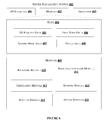
- Figure 2 shows an exemplary block diagram of a node of a VSAN 100 for storing data in a data storage unit in accordance with some embodiments of the present disclosure.
- the first node 101A comprises a first array controller 201 1 , a second array controller 201 2 , and a data storage unit 208.
- the first array controller 201 1 comprises a Small Computer System Interface (SCSI) driver 202 1 , a routing module 203 1 , a routing module 203 2 , a control module 204 1 , a control module 204 2 , a data module 205 1 , a data module 205 2 , a kernel 206 1 and processor cores 207 1 .
- the second array controller 201 2 comprises a Small Computer System Interface (SCSI) driver 202 2 , a routing module 203 3 , a routing module 203 4 , a control module 204 3 , a control module 204 4 , a data module 205 3 , a data module 205 4 , a kernel 206 2 and processor cores 207 2 .
- SCSI Small Computer System Interface
- either the first array controller 201 1 or the second array controller 201 2 takes control of the data storage unit 208.
- Either of the first array controller 201 1 or the second array controller 201 2 help in storing the data in the data storage unit 208.
- the SCSI driver 202 1 facilitates data communication, within the first array controller 201 1 , with the switch 103 and with the server management system 102.
- the SCSI driver 202 1 receives the one or more I/O request messages from the switch 103.
- one of, the routing modules 203 1 and the routing module 203 2 receives the one or more I/O request messages from the SCSI driver 202 1 .
- the routing module 203 1 receives the one or more request messages from the SCSI driver 202 1 .
- the routing module 203 1 then routes the data and the address present in the one or more I/O request messages to corresponding control module 204 1 .
- the control module 204 1 converts the address to an internal address.
- the control module 204 1 forwards the data to corresponding data module 205 1 based on the internal address.
- the data module 205 1 comprises a mapping of the internal address with corresponding physical address of the data storage unit 208 where the data is intended to be stored.
- the data module 205 1 stores the data in the physical address of the data storage unit 208 based on the mapping.
- the data storage unit 208 of each of the plurality of nodes 101 is associated with a corresponding predefined threshold memory.
- the predefined threshold memory is set on total memory of respective data storage unit 208.
- the data storage unit 208 comprises a counter. The value of the counter increases based on amount of data stored in the data storage unit 208.
- the kernel 206 1 monitors the data storage unit 208 for available memory based on the predefined threshold.
- the kernel 206 1 configures the SCSI driver 202 1 to forward the one or more I/O requests to the server management system 102 when the available memory in the data storage unit 208 is less than the predefined threshold memory.
- the kernel 206 1 configures the SCSI driver 202 1 to transmit available memory in the data storage unit 208 to the server management system 102 at predefined intervals of time.
- FIG. 3 shows an exemplary block diagram of a server management system 102 of a VSAN for storing data in a data storage unit in accordance with some embodiments of the present disclosure.
- the server management system 102 comprises a Control Routing Unit (CRU) 301 and a Master Routing Unit (MRU) 302.
- the server management system 102 further comprises a kernel 303 and processor cores 304.
- the CRU 301 receives the one or more I/O request messages from the SCSI driver 202 1 .
- the CRU 301 acts as a temporary storage unit.
- the CRU 301 stores the data present in the one or more I/O request messages temporarily.
- the kernel 303 configures the MRU 302 to identify a second node 101B among the plurality of nodes 101 for storing the data.
- the MRU 302 Upon identifying the second node 101B, the MRU 302 maps address of the first node 101A with address of the second node 101B. Further, the MRU 302 provides instructions to the CRU 301 for transmitting the data to the address of the second node 101B. The CRU 301 transmits the data to the second node 101B for storing the data in the second node 101B.
- FIG. 4 illustrates internal architecture of the server management system 102 in accordance with some embodiments of the present disclosure.
- the server management system 102 may include at least one central processing unit (“CPU” or “processor”) 403 and a memory 402 storing instructions executable by the at least one processor 403.
- the processor 403 may comprise at least one data processor for executing program components for executing user or system-generated requests.
- the memory 402 is communicatively coupled to the processor 403.
- the server management system 102 further comprises an Input/Output (I/O) interface 401.
- the I/O interface 401 is coupled with the processor 403 through which an input signal or/and an output signal is communicated.
- data 404 may be stored within the memory 402.
- the data 404 may include, for example, I/O request data 405, first node data 406, second node data 407 and other data 408.
- I/O request data 404 may include data to be stored and a request message for storing the data.
- the first node data 406 and the second node data 407 may include I/O request message type, available memory in data storage unit 208 of the first node 101A and the second node 101B.
- the I/O request message type may include a read request, a write request, request for editing, etc.
- the data 404 in the memory 402 is processed by modules 409 of the server management system 102.
- the term module refers to an application specific integrated circuit (ASIC), an electronic circuit, a field-programmable gate arrays (FPGA), Programmable System-on-Chip (PSoC), a combinational logic circuit, and/or other suitable components that provide the described functionality.
- ASIC application specific integrated circuit
- FPGA field-programmable gate arrays
- PSoC Programmable System-on-Chip
- a combinational logic circuit and/or other suitable components that provide the described functionality.
- the modules 409 may include, for example, receiving module 410, node identification module 411, generation module 412, mapping module 413, routing module 414 and other modules 415. It will be appreciated that such aforementioned modules 409 may be represented as a single module or a combination of different modules.
- the receiving module 410 receives the one or more I/O request messages from the SCSI driver 202 1 of the first node when available memory in the data storage unit 208 of the first node is less than the predefined threshold memory. Let the data storage unit 208 of the first node 101A be represented as first data storage unit for illustration of this embodiment.
- the receiving module 410 may store the one or more I/O request messages in the CRU 301.
- the receiving module 410 may communicate with the SCSI driver 202 1 through wired interface or wireless interface.
- the node identification module 411 identifies a second node 101B among the plurality of nodes 101 for storing the data.
- the second node is identified based on size of the data and available memory in the data storage unit 208 of the second node 101B. Let the data storage unit 208 of the second node be represented as second data storage unit for illustration of this embodiment.
- the node identification module 411 receives data regarding available memory in data storage unit 208 from each of the plurality of nodes 101.
- the node identification module 411 receives the data regarding available memory in data storage unit 208 from each of the plurality of nodes 101 at predefined intervals of time.
- the node identification module 411 identifies a second node 101B among the plurality of nodes 101 such that available memory in the second data storage unit is greater than the corresponding predefined threshold memory. Further, the second node 101B is identified when the size of the data can be accommodated in the available memory in the second data storage unit 208.
- the generation module 412 generates an ID and address for the first node 101A and the second node 101B, when the server management system 102 receives the one or more I/O request messages from the first node 101A.
- the generation module 412 generates the ID based on cluster of the first node 101A and second node 101B, the array controller 201 used for processing the one or more I/O request messages and the routing module 203 of the array controller 201. Further, the generation module 412 generates an address for the first node 101A and the second node 101B.
- the address for the first node 101A is generated based on the I/O request message type and ID of the first node 101A.
- the generation module generates address for the second node 101B based on the I/O request message type and ID of the second node 101B.
- the ID and address for each of the plurality of nodes 101 is unique.
- the mapping module 413 forms a part of the MRU 302.
- a cluster indicates a group of nodes.
- the first node 101A and the second node 101B may be a part of a same cluster or may be a part of different clusters.
- the VSAN 100 comprises plurality of clusters, each cluster comprising plurality of nodes 101.
- the mapping module 413 receives the address of the first node 101A and the second node 101B and maps the address of the first node 101A with the address of the second node 101B.
- the mapping indicates a source node and a corresponding destination node.
- the mapping module 413 generates a map of all source nodes requesting the server management system 102 for storing the data, and corresponding destination nodes.
- the mapping module 413 forms a part of the MRU 302.
- the routing module 414 routes the data present in the CRU 301 to the second node 101B based on the map generated by the mapping module 413.
- the routing module 414 routes the data to SCSI driver 202 B of the second node 101B for storing the data in the data storage unit 208 B .
- the other modules 415 may include notification module, node monitoring module, etc.
- the notification module may notify administrator of the VSAN 100 regarding available memory of data storage unit 208 of each of the plurality of nodes 101.
- the server management system 102 may include a monitoring unit for monitoring available memory in the data storage unit 208 of each of the plurality of nodes 101.
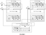
- Figure 5 illustrates management of data storage unit for storing data in accordance with some embodiments of the present disclosure.
- Figure 5 illustrates an example where the data to be stored in the first node 101A is stored in the second node 101B using the server management system 102.
- first array controller 201 A receives the one or more I/O request messages from the switch 103.
- the SCSI driver 202 A1 receives the one or more I/O request messages.
- the SCSI driver 202 A1 forwards the one or more I/O request messages to the routing module 203 A1 .
- the routing module 203 A1 transmits the data and address present in the one or more I/O request messages to the corresponding control module 204 A1 .
- the control module 204 A1 routes the data to be stored in the data storage unit 208 A to corresponding data module 205 A1 .
- the predefined threshold memory for available memory be 10% of total memory of the data storage unit 208 A .
- the kernel 206 A1 detects that the available memory in the data storage unit 208 A is less than the predefined threshold memory and refrains from storing the data in the data storage unit 208 A . Therefore, the kernel 206 A1 configures the SCSI driver 202 A1 to forward the one or more I/O request messages to the sever management system 102 for storing the data.
- the receiving module 410 of the server management system 102 receives the one or more I/O request messages from the SCSI driver 202 A1 from the first node 101A. Further, the receiving module 410 stores the data in the CRU 301.
- the node identification module 411 may have access to the data regarding available memory in data storage unit 208 of each of the plurality of nodes 101. Now, the node identification module 411 traverses each of the plurality of nodes 101 and identifies the second node 101B based on the predefined threshold memory and the size of data. Let us consider that the data storage unit 208 B has available memory greater than the corresponding predefined threshold memory. Further, the generation module 413 generates ID and address for the first node 101A and the second node 101B.
- the source ID indicates that the first node is from cluster 2, the one or more I/O request messages are processed by the first array controller 201 A1 and the routing module 203 A1 has received the one or more I/O request messages.
- the source address indicates the one or more I/O request messages type, the array controller 201 used to process the one or more I/O request messages.
- the ID and address of the second node 101B indicates that the second node 101B lies in cluster 1.
- the array controller 201 B and the routing module 203 B1 should be used for storing the data in the data storage unit 208 B . Then, the routing module 414 routes the data stored in the CRU 301 to the second node 101B based on the mapping.
- the SCSI driver 202 B1 of the second node 101B receives the data and forwards the data to the routing module 203 B1 of the first array controller 201 B .
- the routing module 203 B1 routes the data to corresponding control module 204 B1 and in turn the control module 204 B1 routes the data to corresponding data module 205 B1 .
- the data module 205 B1 stores the data in the data storage unit 208 B .
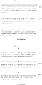
- Figure 6A and Figure 6B show an exemplary flow chart illustrating a method for storing data in a data storage device of a VSAN 100.
- the method 600 and 603 may comprise one or more steps for storing data in a data storage unit in accordance with some embodiments of the present disclosure.
- the method 600 and 603 may be described in the general context of computer executable instructions.
- computer executable instructions can include routines, programs, objects, components, data structures, procedures, modules, and functions, which perform particular functions or implement particular abstract data types.
- the receiving module 410 receives one or more I/O request messages from the first node 101 A of the VSAN 100.
- the receiving module 410 receives the one or more I/O request messages when the available memory in the data storage unit 208 A is less than the predefined threshold memory. Further, the receiving module stores the data present in the one or more I/O request messages in the CRU 301.
- the node identification module 411 identifies the second node 101B from the plurality of nodes 101.
- the node identification module 411 receives the data regarding available memory in data storage unit 208 from each of the plurality of nodes 101.
- the second node 101B is identified such that the available memory in the data storage unit 208 B is greater than the corresponding threshold memory. Also, the available memory can accommodate the size of the data.
- the routing module 414 routes the data to the second node 101B for storing the data in the data storage unit 208 B .
- the step 603 can be further divided into 603A, 603B and 603C.
- Figure 6B shows the method steps for routing the data to the second node 101B.
- the generation module 412 generates an ID and address for the first node 101A.
- the ID of the first node 101A indicates the cluster of the first node 101A, the array controller 201 used for processing the one or more I/O request messages and the routing module 203 used to route the one or more I/O request messages.
- the address is generated based on the ID of the first node 101A.
- the address comprises one or more I/O request messages type and the array controller 201 which has processed the one or more I/O request messages.
- the generation module 412 generates an ID and address for the second node 101B.
- the ID of the second node 101B indicates the cluster of the second node 101B, the array controller 201 to be used for processing the one or more I/O request messages and the routing module 203 to be used to route the one or more I/O request messages for storing the data on the data storage unit 208 B .
- the address is generated based on the ID of the second node 101B.
- the address comprises one or more I/O request messages type and the array controller 201 which has to be used to process the one or more I/O request messages.
- the mapping module 413 maps the address of the first node 101A with the address of the second node 101.
- the map generated provides a link between the first node 101A and the second node 101B.
- the link can be used to track the data which was intended to be stored in the first node 101A, but is stored in the second node 101B.
- the routing module 414 routes the one or more I/O request messages to the second module 101B for storing the data in the data storage unit 208 B .
- FIG. 7 illustrates a block diagram of an exemplary computer system 700 for implementing embodiments consistent with the present disclosure.
- the computer system 700 is used to implement the method for storing data in a data storage unit 208 of a VSAN 100.
- the computer system 700 may comprise a central processing unit (“CPU” or "processor") 702.
- the processor 702 may comprise at least one data processor for executing program components for dynamic resource allocation at run time.
- the processor 702 may include specialized processing units such as integrated system (bus) controllers, memory management control units, floating point units, graphics processing units, digital signal processing units, etc.
- the processor 702 may be disposed in communication with one or more input/output (I/O) devices (not shown) via I/O interface 701.
- the I/O interface 701 may employ communication protocols/methods such as, without limitation, audio, analog, digital, monoaural, RCA, stereo, IEEE-1394, serial bus, universal serial bus (USB), infrared, PS/2, BNC, coaxial, component, composite, digital visual interface (DVI), high-definition multimedia interface (HDMI), RF antennas, S-Video, VGA, IEEE 802.n /b/g/n/x, Bluetooth, cellular (e.g., code-division multiple access (CDMA), high-speed packet access (HSPA+), global system for mobile communications (GSM), long-term evolution (LTE), WiMax, or the like), etc.
- CDMA code-division multiple access
- HSPA+ high-speed packet access
- GSM global system for mobile communications
- LTE long-term evolution
- WiMax wireless wide area network
- the computer system 700 may communicate with one or more I/O devices.
- the input device 710 may be an antenna, keyboard, mouse, joystick, (infrared) remote control, camera, card reader, fax machine, dongle, biometric reader, microphone, touch screen, touchpad, trackball, stylus, scanner, storage device, transceiver, video device/source, etc.
- the output device 711 may be a printer, fax machine, video display (e.g., cathode ray tube (CRT), liquid crystal display (LCD), light-emitting diode (LED), plasma, Plasma display panel (PDP), Organic light-emitting diode display (OLED) or the like), audio speaker, etc.
- CTR cathode ray tube
- LCD liquid crystal display
- LED light-emitting diode
- PDP Plasma display panel
- OLED Organic light-emitting diode display
- the computer system 700 is connected to the service operator through a communication network 709.
- the processor 702 may be disposed in communication with the communication network 709 via a network interface 703.
- the network interface 703 may communicate with the communication network 709.
- the network interface 703 may employ connection protocols including, without limitation, direct connect, Ethernet (e.g., twisted pair 10/100/1000 Base T), transmission control protocol/Internet protocol (TCP/IP), token ring, IEEE 802.11a/b/g/n/x, etc.
- the communication network 709 may include, without limitation, a direct interconnection, e-commerce network, a peer to peer (P2P) network, local area network (LAN), wide area network (WAN), wireless network (e.g., using Wireless Application Protocol), the Internet, Wi-Fi, etc.
- P2P peer to peer
- LAN local area network
- WAN wide area network
- wireless network e.g., using Wireless Application Protocol
- the Internet e.g., Wi-Fi, etc.
- the processor 702 may be disposed in communication with a memory 705 (e.g., RAM, ROM, etc. not shown in Figure 7 ) via a storage interface 704.
- the storage interface 704 may connect to memory 705 including, without limitation, memory drives, removable disc drives, etc., employing connection protocols such as serial advanced technology attachment (SATA), Integrated Drive Electronics (IDE), IEEE-1394, Universal Serial Bus (USB), fibre channel, Small Computer Systems Interface (SCSI), etc.
- the memory drives may further include a drum, magnetic disc drive, magneto-optical drive, optical drive, Redundant Array of Independent Discs (RAID), solid-state memory devices, solid-state drives, etc.
- the memory 705 may store a collection of program or database components, including, without limitation, user interface 706, an operating system 707, web server 708 etc.
- computer system 700 may store user/application data 706, such as the data, variables, records, etc. as described in this disclosure.
- databases may be implemented as fault-tolerant, relational, scalable, secure databases such as Oracle or Sybase.
- the operating system 707 may facilitate resource management and operation of the computer system 700.
- Examples of operating systems include, without limitation, Apple Macintosh OS X, Unix, Unix-like system distributions (e.g., Berkeley Software Distribution (BSD), FreeBSD, NetBSD, OpenBSD, etc.), Linux distributions (e.g., Red Hat, Ubuntu, Kubuntu, etc.), IBM OS/2, Microsoft Windows (XP, Vista/7/8, 10 etc.), Apple iOS, Google Android, Blackberry OS, or the like.
- the computer system 700 may implement a web browser 708 stored program component.
- the web browser 708 may be a hypertext viewing application, such as Microsoft Internet Explorer, Google Chrome, Mozilla Firefox, Apple Safari, etc. Secure web browsing may be provided using Secure Hypertext Transport Protocol (HTTPS), Secure Sockets Layer (SSL), Transport Layer Security (TLS), etc. Web browsers 708 may utilize facilities such as AJAX, DHTML, Adobe Flash, JavaScript, Java, Application Programming Interfaces (APIs), etc.
- the computer system 700 may implement a mail server stored program component.
- the mail server may be an Internet mail server such as Microsoft Exchange, or the like.
- the mail server may utilize facilities such as ASP, ActiveX, ANSI C++/C#, Microsoft .NET, CGI scripts, Java, JavaScript, PERL, PHP, Python, WebObjects, etc.
- the mail server may utilize communication protocols such as Internet Message Access Protocol (IMAP), Messaging Application Programming Interface (MAPI), Microsoft Exchange, Post Office Protocol (POP), Simple Mail Transfer Protocol (SMTP), or the like.
- IMAP Internet Message Access Protocol
- MAPI Messaging Application Programming Interface
- PMP Post Office Protocol
- SMTP Simple Mail Transfer Protocol
- the computer system 700 may implement a mail client stored program component.
- the mail client may be a mail viewing application, such as Apple Mail, Microsoft Entourage, Microsoft Outlook, Mozilla Thunderbird, etc.
- the computer system 700 is associated with plurality of nodes 712.
- Each of the plurality of nodes 712 provide the computer system 500 with data related to available memory in the corresponding data storage unit 208.
- the present disclosure discloses a method and a system for distributing load to different data storage system units in a VSAN.
- processing efficiency of individual cluster increases.
- the cluster utilization is increased by storing data in data storage units of different nodes.
- the disclosed system and method is compatible with existing VSAN architecture. Hence, cost of implementing the disclosed system is low.
- the data can be stored in data storage unit of different cluster associated with the server management system, therefore the system managing memory efficiently in the VSAN.
Landscapes
- Engineering & Computer Science (AREA)
- Theoretical Computer Science (AREA)
- Human Computer Interaction (AREA)
- Physics & Mathematics (AREA)
- General Engineering & Computer Science (AREA)
- General Physics & Mathematics (AREA)
- Computer Networks & Wireless Communication (AREA)
- Signal Processing (AREA)
- Computer And Data Communications (AREA)
- Information Retrieval, Db Structures And Fs Structures Therefor (AREA)
- Hardware Redundancy (AREA)
Abstract
The present disclosure discloses a method and a system for storing data in a data storage system of a Virtual Storage Area Network (VSAN). The method comprises receiving, by a server management system, a request message for storing data, from an array controller of a first node among a plurality of nodes of a Virtual Storage Area Network (VSAN) cluster, where each of the plurality of nodes comprises a pair of array controllers and a data storage unit, identifying a second node from the plurality of nodes, for storing the data in a data storage unit of the second node and routing the data to an array controller of the second node, for storing the data in the data storage unit, for effectively utilizing the data storage unit of the VSAN network.
Description
- The present disclosure relates to data storage in a Virtual Storage Area Network (VSAN). More particularly, but not exclusively, the present disclosure relates to effective utilization of data storage units for storing data in the VSAN.
- A storage area network (SAN) is a dedicated high-speed network for interconnecting and presenting a shared pool of storage devices to multiple servers. SAN is primarily used to enhance performance of the storage devices as they appear as a single locally attached device to the servers, where the servers are centrally managed. Virtual Storage Area Network (VSAN) is a logical partition in the SAN. The VSAN allows data traffic of the servers to be isolated within specific portions of SAN so that system of storage devices is scaled out and is easy to configure. The main objective of the VSAN is the easy management of subscribers which can be added or relocated without the need for changing the physical layout of storage. Another objective of the VSAN is to provide data redundancy which minimizes the risk of data loss.
- A conventional VSAN storage array includes a brick as a basic building block. The brick of the VSAN architecture comprises two storage controllers for receiving Input/Output (I/O) request from host machines connected to the bricks. The brick further comprises a Disk Array Enclosure (DAE) for holding multiple Solid State Drives (SSD) for storing data, and backup units. Each storage controller has multi-core Central Processing Units (CPUs) for processing I/O tasks. In the conventional architecture of VSAN, the bricks may be clustered together to increase performance and capacity of the system. A cluster in VSAN may include two or more bricks. When storage space in a brick of the cluster is utilized up to a threshold, an alert is sent to a user to scale out the system by including additional bricks in the system. For example, the threshold may be 90% of total storage available in the brick. Thus, the user has to manually instruct the system for including additional bricks in the system. Also, inclusion of additional bricks in the system may cost substantial amount of money. Additionally, if the threshold is reached, a new I/O request has to wait in a process queue to be processed, hence increasing latency to process the request.
- Furthermore, the existing VSAN architecture only alerts the user, and does not provide automatic inclusion of bricks to the VSAN network, i.e. in the existing architecture, there does not exist a mechanism to route the data to different a secondary data storage unit when primary data storage unit is overloaded. Therefore, the bricks of the VSAN network is not fully utilized. Also, in the conventional VSAN architecture, an I/O request cannot be passed to different bricks of the VSAN. Thus, processing load of a brick is not efficiently managed.
- The information disclosed in this background of the disclosure section is only for enhancement of understanding of the general background of the invention and should not be taken as an acknowledgement or any form of suggestion that this information forms the prior art already known to a person skilled in the art.
- In an embodiment, the present disclosure presents a method for storing data in a data storage unit of a Virtual Storage Area Network (VSAN). The method comprises receiving, by a server management system, a request message for storing data, from an array controller of a first node among a plurality of nodes of a Virtual Storage Area Network (VSAN) cluster, where each of the plurality of nodes comprises a pair of array controllers and a data storage unit, identifying a second node from the plurality of nodes, for storing the data in a data storage unit of the second node and routing the data to an array controller of the second node, for storing the data in the data storage unit, for effectively utilizing the data storage unit of the VSAN network.
- In one embodiment, the present disclosure presents a system for storing data in a data storage unit of a Virtual Storage Area Network (VSAN). The system comprises a processor and a memory. The processor is configured to receive a request message for storing data, from an array controller of a first node among a plurality of nodes of a Virtual Storage Area Network (VSAN) cluster, wherein each of the plurality of nodes comprises a pair of array controllers and a data storage unit, identify a second node from the plurality of nodes, for storing the data in a data storage unit of the second node and route the data to an array controller of the second node, for storing the data in the data storage unit, for effectively utilizing the data storage unit of the VSAN network.
- The foregoing summary is illustrative only and is not intended to be in any way limiting. In addition to the illustrative aspects, embodiments, and features described above, further aspects, embodiments, and features will become apparent by reference to the drawings and the following detailed description.
- The novel features and characteristic of the disclosure are set forth in the appended claims. The disclosure itself, however, as well as a preferred mode of use, further objectives and advantages thereof, will best be understood by reference to the following detailed description of an illustrative embodiment when read in conjunction with the accompanying figures. One or more embodiments are now described, by way of example only, with reference to the accompanying figures wherein like reference numerals represent like elements and in which:
-
Figure 1 shows a VSAN architecture for storing data in a data storage unit in accordance with some embodiments of the present disclosure; -
Figure 2 shows an exemplary block diagram of a node of a VSAN for storing data in a data storage unit in accordance with some embodiments of the present disclosure; -
Figure 3 shows an exemplary block diagram of a server management system of a VSAN for storing data in a data storage unit in accordance with some embodiments of the present disclosure; -
Figure 4 shows internal architecture of a server management system for storing data in a data storage unit in accordance with some embodiments of the present disclosure; -
Figure 5 illustrates management of data storage unit for storing data in accordance with some embodiments of the present disclosure; -
Figure 6A and Figure 6B show an exemplary flow chart illustrating a method for storing data in a data storage unit in accordance with some embodiments of the present disclosure; and -
Figure 7 shows a general-purpose computer system for storing data in a data storage unit in accordance with some embodiments of the present disclosure. - It should be appreciated by those skilled in the art that any block diagrams herein represent conceptual views of illustrative systems embodying the principles of the present subject matter. Similarly, it will be appreciated that any flow charts, flow diagrams, state transition diagrams, pseudo code, and the like represent various processes which may be substantially represented in computer readable medium and executed by a computer or processor, whether or not such computer or processor is explicitly shown.
- While the disclosure is susceptible to various modifications and alternative forms, specific embodiment thereof has been shown by way of example in the drawings and will be described in detail below. It should be understood, however that it is not intended to limit the disclosure to the particular forms disclosed, but on the contrary, the disclosure is to cover all modifications, equivalents, and alternative falling within the scope of the disclosure.
- In an embodiment, the present disclosure discloses a server management system for storing data in a data storage unit of a Virtual Storage Area Network (VSAN). The server management system receives a request message from a first node of a VSAN, for storing data, when a data storage unit of the first node cannot accommodate the data. Then, the server management system identifies a second node among plurality of nodes of the VSAN for storing the data in data storage unit of the second node. Thus, the present disclosure provides a system for utilizing data storage unit of the VSAN.
-
Figure 1 shows aVSAN 100 architecture for storing data in a data storage unit in accordance with some embodiments of the present disclosure. TheVSAN 100 comprisesnode 101A,node 101B,node 101C, ...,node 101N, aserver management system 102 and aswitch 103. The VSAN 100 is connected to ahost device 104. For illustration, only oneuser device 104 is shown inFigure 1 . However, plurality of user devices can be connected to a single node. Thenode 101A,node 101B, node 101c, ...,node 101N may be collectively represented as plurality ofnodes 101. The term plurality ofnodes 101 is used throughout this disclosure to represent the collective representation ofnode 101A,node 101B,node 101C, ...,node 101N. Each of the plurality ofnodes 101 is connected to theserver management system 102, either by wired interface or wireless interface. In an embodiment, each of the plurality ofnodes 101 may be a server. Further, each of the plurality ofnodes 101 may be connected to ahost device 104. For illustration, let us consider thatnode 101A is connected to thehost device 104, through theswitch 103. Theswitch 103 receives one or more Input/Output (I/O) request messages from thehost device 104. The one or more I/O request messages may comprise instructions for storing data, along with data to be stored. The one or more I/O request message may further comprise address for storing the data. Then, theswitch 103 forwards the one or more I/O request messages to corresponding node among the plurality ofnodes 101 based on the address. For illustration purpose, theswitch 103 is connected to thenode 101A inFigure 1 . However, in a network, theswitch 103 will be connected to one or more nodes. For convenience, let thenode 101A be represented asfirst node 101A. Thefirst node 101A receives the one or more I/O request messages from theswitch 103 for storing the data. Thefirst node 101A forwards the one or more I/O request messages to theserver management system 102 for storing the data in a second node among the plurality ofnodes 101, when thefirst node 101A cannot accommodate to store the data. Here, thefirst node 101A forwards the one or more I/O request messages to theserver management system 102 when data availability in a data storage unit (not shown inFigure 1 ) associated with thefirst node 101A is less than a predefined threshold memory. Theserver management system 102 identifies a second node among the plurality ofnodes 101 and forwards the one or more I/O request messages to the second node for storing the data in a data storage unit associated with the second node. For illustration, let us consider that the second node be represented bynode 101B. - In an embodiment, the
host device 104 may be a Personal Digital Assistant (PDA), a laptop, a Personal Computer (PC), a smartphone or any other computing unit. -
Figure 2 shows an exemplary block diagram of a node of aVSAN 100 for storing data in a data storage unit in accordance with some embodiments of the present disclosure. For illustrationFigure 2 , let us consider thefirst node 101A. However, any node among the plurality ofnodes 101 can be considered. Thefirst node 101A comprises afirst array controller 2011, asecond array controller 2012, and adata storage unit 208. Further, thefirst array controller 2011 comprises a Small Computer System Interface (SCSI) driver 2021, arouting module 2031, arouting module 2032, a control module 2041, a control module 2042, adata module 2051, adata module 2052, akernel 2061 and processor cores 2071. Thesecond array controller 2012 comprises a Small Computer System Interface (SCSI) driver 2022, arouting module 2033, arouting module 2034, a control module 2043, a control module 2044, adata module 2053, adata module 2054, akernel 2062 and processor cores 2072. - In an embodiment, for processing an I/O request, either the
first array controller 2011 or thesecond array controller 2012, takes control of thedata storage unit 208. Either of thefirst array controller 2011 or thesecond array controller 2012 help in storing the data in thedata storage unit 208. For illustration, let us consider that thefirst array controller 2011 receives the I/O request from thehost device 104 through theswitch 103, for storing the data in thedata storage unit 208. The SCSI driver 2021 facilitates data communication, within thefirst array controller 2011, with theswitch 103 and with theserver management system 102. The SCSI driver 2021 receives the one or more I/O request messages from theswitch 103. Further, one of, therouting modules 2031 and therouting module 2032 receives the one or more I/O request messages from the SCSI driver 2021. Let us consider that therouting module 2031 receives the one or more request messages from the SCSI driver 2021. Therouting module 2031 then routes the data and the address present in the one or more I/O request messages to corresponding control module 2041. The control module 2041 converts the address to an internal address. Then, the control module 2041 forwards the data to correspondingdata module 2051 based on the internal address. Thedata module 2051 comprises a mapping of the internal address with corresponding physical address of thedata storage unit 208 where the data is intended to be stored. Thedata module 2051 stores the data in the physical address of thedata storage unit 208 based on the mapping. - In an embodiment, the
data storage unit 208 of each of the plurality ofnodes 101 is associated with a corresponding predefined threshold memory. The predefined threshold memory is set on total memory of respectivedata storage unit 208. - In an embodiment, the
data storage unit 208 comprises a counter. The value of the counter increases based on amount of data stored in thedata storage unit 208. Thekernel 2061 monitors thedata storage unit 208 for available memory based on the predefined threshold. Thekernel 2061 configures the SCSI driver 2021 to forward the one or more I/O requests to theserver management system 102 when the available memory in thedata storage unit 208 is less than the predefined threshold memory. Also, thekernel 2061 configures the SCSI driver 2021 to transmit available memory in thedata storage unit 208 to theserver management system 102 at predefined intervals of time. -
Figure 3 shows an exemplary block diagram of aserver management system 102 of a VSAN for storing data in a data storage unit in accordance with some embodiments of the present disclosure. Theserver management system 102 comprises a Control Routing Unit (CRU) 301 and a Master Routing Unit (MRU) 302. Theserver management system 102 further comprises akernel 303 andprocessor cores 304. TheCRU 301 receives the one or more I/O request messages from the SCSI driver 2021. TheCRU 301 acts as a temporary storage unit. TheCRU 301 stores the data present in the one or more I/O request messages temporarily. Then, thekernel 303 configures theMRU 302 to identify asecond node 101B among the plurality ofnodes 101 for storing the data. Upon identifying thesecond node 101B, theMRU 302 maps address of thefirst node 101A with address of thesecond node 101B. Further, theMRU 302 provides instructions to theCRU 301 for transmitting the data to the address of thesecond node 101B. TheCRU 301 transmits the data to thesecond node 101B for storing the data in thesecond node 101B. -
Figure 4 illustrates internal architecture of theserver management system 102 in accordance with some embodiments of the present disclosure. Theserver management system 102 may include at least one central processing unit ("CPU" or "processor") 403 and amemory 402 storing instructions executable by the at least oneprocessor 403. Theprocessor 403 may comprise at least one data processor for executing program components for executing user or system-generated requests. Thememory 402 is communicatively coupled to theprocessor 403. Theserver management system 102 further comprises an Input/Output (I/O)interface 401. The I/O interface 401 is coupled with theprocessor 403 through which an input signal or/and an output signal is communicated. - In an embodiment,
data 404 may be stored within thememory 402. Thedata 404 may include, for example, I/O request data 405,first node data 406,second node data 407 andother data 408. - In an embodiment, I/
O request data 404 may include data to be stored and a request message for storing the data. In an embodiment, thefirst node data 406 and thesecond node data 407 may include I/O request message type, available memory indata storage unit 208 of thefirst node 101A and thesecond node 101B. In an embodiment, the I/O request message type may include a read request, a write request, request for editing, etc. - In an embodiment, the
data 404 in thememory 402 is processed bymodules 409 of theserver management system 102. As used herein, the term module refers to an application specific integrated circuit (ASIC), an electronic circuit, a field-programmable gate arrays (FPGA), Programmable System-on-Chip (PSoC), a combinational logic circuit, and/or other suitable components that provide the described functionality. The saidmodules 409 when configured with the functionality defined in the present disclosure will result in a novel hardware. - In one implementation, the
modules 409 may include, for example, receivingmodule 410,node identification module 411,generation module 412,mapping module 413,routing module 414 andother modules 415. It will be appreciated that suchaforementioned modules 409 may be represented as a single module or a combination of different modules. - In an embodiment, the receiving
module 410 receives the one or more I/O request messages from the SCSI driver 2021 of the first node when available memory in thedata storage unit 208 of the first node is less than the predefined threshold memory. Let thedata storage unit 208 of thefirst node 101A be represented as first data storage unit for illustration of this embodiment. The receivingmodule 410 may store the one or more I/O request messages in theCRU 301. The receivingmodule 410 may communicate with the SCSI driver 2021 through wired interface or wireless interface. - In an embodiment, the
node identification module 411 identifies asecond node 101B among the plurality ofnodes 101 for storing the data. Here, the second node is identified based on size of the data and available memory in thedata storage unit 208 of thesecond node 101B. Let thedata storage unit 208 of the second node be represented as second data storage unit for illustration of this embodiment. In an embodiment, thenode identification module 411 receives data regarding available memory indata storage unit 208 from each of the plurality ofnodes 101. In an embodiment, thenode identification module 411 receives the data regarding available memory indata storage unit 208 from each of the plurality ofnodes 101 at predefined intervals of time. Further, thenode identification module 411 identifies asecond node 101B among the plurality ofnodes 101 such that available memory in the second data storage unit is greater than the corresponding predefined threshold memory. Further, thesecond node 101B is identified when the size of the data can be accommodated in the available memory in the seconddata storage unit 208. - In an embodiment, the
generation module 412 generates an ID and address for thefirst node 101A and thesecond node 101B, when theserver management system 102 receives the one or more I/O request messages from thefirst node 101A. Thegeneration module 412 generates the ID based on cluster of thefirst node 101A andsecond node 101B, thearray controller 201 used for processing the one or more I/O request messages and therouting module 203 of thearray controller 201. Further, thegeneration module 412 generates an address for thefirst node 101A and thesecond node 101B. The address for thefirst node 101A is generated based on the I/O request message type and ID of thefirst node 101A. Likewise, the generation module generates address for thesecond node 101B based on the I/O request message type and ID of thesecond node 101B. In an embodiment, the ID and address for each of the plurality ofnodes 101 is unique. In an embodiment, themapping module 413 forms a part of theMRU 302. - In an embodiment, a cluster indicates a group of nodes. In an embodiment, the
first node 101A and thesecond node 101B may be a part of a same cluster or may be a part of different clusters. TheVSAN 100 comprises plurality of clusters, each cluster comprising plurality ofnodes 101. - In an embodiment, the
mapping module 413 receives the address of thefirst node 101A and thesecond node 101B and maps the address of thefirst node 101A with the address of thesecond node 101B. The mapping indicates a source node and a corresponding destination node. Thus, themapping module 413 generates a map of all source nodes requesting theserver management system 102 for storing the data, and corresponding destination nodes. In an embodiment, themapping module 413 forms a part of theMRU 302. - In an embodiment, the
routing module 414 routes the data present in theCRU 301 to thesecond node 101B based on the map generated by themapping module 413. Here, therouting module 414 routes the data to SCSI driver 202B of thesecond node 101B for storing the data in thedata storage unit 208B. - In an embodiment, the
other modules 415 may include notification module, node monitoring module, etc. In an embodiment, the notification module may notify administrator of theVSAN 100 regarding available memory ofdata storage unit 208 of each of the plurality ofnodes 101. In an embodiment, theserver management system 102 may include a monitoring unit for monitoring available memory in thedata storage unit 208 of each of the plurality ofnodes 101. -
Figure 5 illustrates management of data storage unit for storing data in accordance with some embodiments of the present disclosure.Figure 5 illustrates an example where the data to be stored in thefirst node 101A is stored in thesecond node 101B using theserver management system 102. Considerfirst array controller 201A receives the one or more I/O request messages from theswitch 103. Particularly, the SCSI driver 202A1 receives the one or more I/O request messages. Further, the SCSI driver 202A1 forwards the one or more I/O request messages to therouting module 203A1. Then, therouting module 203A1 transmits the data and address present in the one or more I/O request messages to the corresponding control module 204A1. In turn, the control module 204A1 routes the data to be stored in thedata storage unit 208A tocorresponding data module 205A1. Let the predefined threshold memory for available memory be 10% of total memory of thedata storage unit 208A. Consider a scenario where the available memory of thedata storage unit 208A is less than the predefined threshold memory. Here, thekernel 206A1 detects that the available memory in thedata storage unit 208A is less than the predefined threshold memory and refrains from storing the data in thedata storage unit 208A. Therefore, thekernel 206A1 configures the SCSI driver 202A1 to forward the one or more I/O request messages to the severmanagement system 102 for storing the data. The receivingmodule 410 of theserver management system 102 receives the one or more I/O request messages from the SCSI driver 202A1 from thefirst node 101A. Further, the receivingmodule 410 stores the data in theCRU 301. Consider that thenode identification module 411 may have access to the data regarding available memory indata storage unit 208 of each of the plurality ofnodes 101. Now, thenode identification module 411 traverses each of the plurality ofnodes 101 and identifies thesecond node 101B based on the predefined threshold memory and the size of data. Let us consider that thedata storage unit 208B has available memory greater than the corresponding predefined threshold memory. Further, thegeneration module 413 generates ID and address for thefirst node 101A and thesecond node 101B. Table 1 shows an example of ID and address for thefirst node 101A and thesecond node 101B and the mapping of the address of thefirst node 101A with the address of thesecond node 101B.TABLE 1 Source ID Source Address Destination ID Destination Address CL-2-AC-1-RM-1=6 #4067-AC-1-6 CL-1-AC-1-RM-1=1 #4067-AC-1-1 - From Table 1, the source ID indicates that the first node is from cluster 2, the one or more I/O request messages are processed by the
first array controller 201A1 and therouting module 203A1 has received the one or more I/O request messages. Further, the source address indicates the one or more I/O request messages type, thearray controller 201 used to process the one or more I/O request messages. Likewise, the ID and address of thesecond node 101B indicates that thesecond node 101B lies in cluster 1. Further, thearray controller 201B and therouting module 203B1 should be used for storing the data in thedata storage unit 208B. Then, therouting module 414 routes the data stored in theCRU 301 to thesecond node 101B based on the mapping. The SCSI driver 202B1 of thesecond node 101B receives the data and forwards the data to therouting module 203B1 of thefirst array controller 201B. Therouting module 203B1 routes the data to corresponding control module 204B1 and in turn the control module 204B1 routes the data to correspondingdata module 205B1. Then, thedata module 205B1 stores the data in thedata storage unit 208B. -
Figure 6A and Figure 6B show an exemplary flow chart illustrating a method for storing data in a data storage device of aVSAN 100. - As illustrated in
Figure 6A and Figure 6B , themethod method - The order in which the
method - At
step 601, the receivingmodule 410 receives one or more I/O request messages from thefirst node 101A of theVSAN 100. Here, the receivingmodule 410 receives the one or more I/O request messages when the available memory in thedata storage unit 208A is less than the predefined threshold memory. Further, the receiving module stores the data present in the one or more I/O request messages in theCRU 301. - At
step 602, thenode identification module 411 identifies thesecond node 101B from the plurality ofnodes 101. In an embodiment, thenode identification module 411 receives the data regarding available memory indata storage unit 208 from each of the plurality ofnodes 101. Thesecond node 101B is identified such that the available memory in thedata storage unit 208B is greater than the corresponding threshold memory. Also, the available memory can accommodate the size of the data. - At
step 603, therouting module 414 routes the data to thesecond node 101B for storing the data in thedata storage unit 208B. Thestep 603 can be further divided into 603A, 603B and 603C.Figure 6B shows the method steps for routing the data to thesecond node 101B. - At
step 603A, thegeneration module 412 generates an ID and address for thefirst node 101A. Here, the ID of thefirst node 101A indicates the cluster of thefirst node 101A, thearray controller 201 used for processing the one or more I/O request messages and therouting module 203 used to route the one or more I/O request messages. Further, the address is generated based on the ID of thefirst node 101A. The address comprises one or more I/O request messages type and thearray controller 201 which has processed the one or more I/O request messages. - At
step 603B, thegeneration module 412 generates an ID and address for thesecond node 101B. Here, the ID of thesecond node 101B indicates the cluster of thesecond node 101B, thearray controller 201 to be used for processing the one or more I/O request messages and therouting module 203 to be used to route the one or more I/O request messages for storing the data on thedata storage unit 208B. Further, the address is generated based on the ID of thesecond node 101B. The address comprises one or more I/O request messages type and thearray controller 201 which has to be used to process the one or more I/O request messages. - At
step 603C, themapping module 413 maps the address of thefirst node 101A with the address of thesecond node 101. The map generated provides a link between thefirst node 101A and thesecond node 101B. Thus, the link can be used to track the data which was intended to be stored in thefirst node 101A, but is stored in thesecond node 101B. - Referring back to step 603 of
Figure 6 , therouting module 414 routes the one or more I/O request messages to thesecond module 101B for storing the data in thedata storage unit 208B. -
Figure 7 illustrates a block diagram of anexemplary computer system 700 for implementing embodiments consistent with the present disclosure. In an embodiment, thecomputer system 700 is used to implement the method for storing data in adata storage unit 208 of aVSAN 100. Thecomputer system 700 may comprise a central processing unit ("CPU" or "processor") 702. Theprocessor 702 may comprise at least one data processor for executing program components for dynamic resource allocation at run time. Theprocessor 702 may include specialized processing units such as integrated system (bus) controllers, memory management control units, floating point units, graphics processing units, digital signal processing units, etc. - The
processor 702 may be disposed in communication with one or more input/output (I/O) devices (not shown) via I/O interface 701. The I/O interface 701 may employ communication protocols/methods such as, without limitation, audio, analog, digital, monoaural, RCA, stereo, IEEE-1394, serial bus, universal serial bus (USB), infrared, PS/2, BNC, coaxial, component, composite, digital visual interface (DVI), high-definition multimedia interface (HDMI), RF antennas, S-Video, VGA, IEEE 802.n /b/g/n/x, Bluetooth, cellular (e.g., code-division multiple access (CDMA), high-speed packet access (HSPA+), global system for mobile communications (GSM), long-term evolution (LTE), WiMax, or the like), etc. - Using the I/
O interface 701, thecomputer system 700 may communicate with one or more I/O devices. For example, theinput device 710 may be an antenna, keyboard, mouse, joystick, (infrared) remote control, camera, card reader, fax machine, dongle, biometric reader, microphone, touch screen, touchpad, trackball, stylus, scanner, storage device, transceiver, video device/source, etc. Theoutput device 711 may be a printer, fax machine, video display (e.g., cathode ray tube (CRT), liquid crystal display (LCD), light-emitting diode (LED), plasma, Plasma display panel (PDP), Organic light-emitting diode display (OLED) or the like), audio speaker, etc. - In some embodiments, the
computer system 700 is connected to the service operator through acommunication network 709. Theprocessor 702 may be disposed in communication with thecommunication network 709 via anetwork interface 703. Thenetwork interface 703 may communicate with thecommunication network 709. Thenetwork interface 703 may employ connection protocols including, without limitation, direct connect, Ethernet (e.g., twisted pair 10/100/1000 Base T), transmission control protocol/Internet protocol (TCP/IP), token ring, IEEE 802.11a/b/g/n/x, etc. Thecommunication network 709 may include, without limitation, a direct interconnection, e-commerce network, a peer to peer (P2P) network, local area network (LAN), wide area network (WAN), wireless network (e.g., using Wireless Application Protocol), the Internet, Wi-Fi, etc. Using thenetwork interface 703 and thecommunication network 709, thecomputer system 700 may communicate with the one or more service operators. - In some embodiments, the
processor 702 may be disposed in communication with a memory 705 (e.g., RAM, ROM, etc. not shown inFigure 7 ) via astorage interface 704. Thestorage interface 704 may connect tomemory 705 including, without limitation, memory drives, removable disc drives, etc., employing connection protocols such as serial advanced technology attachment (SATA), Integrated Drive Electronics (IDE), IEEE-1394, Universal Serial Bus (USB), fibre channel, Small Computer Systems Interface (SCSI), etc. The memory drives may further include a drum, magnetic disc drive, magneto-optical drive, optical drive, Redundant Array of Independent Discs (RAID), solid-state memory devices, solid-state drives, etc. - The
memory 705 may store a collection of program or database components, including, without limitation, user interface 706, anoperating system 707,web server 708 etc. In some embodiments,computer system 700 may store user/application data 706, such as the data, variables, records, etc. as described in this disclosure. Such databases may be implemented as fault-tolerant, relational, scalable, secure databases such as Oracle or Sybase. - The
operating system 707 may facilitate resource management and operation of thecomputer system 700. Examples of operating systems include, without limitation, Apple Macintosh OS X, Unix, Unix-like system distributions (e.g., Berkeley Software Distribution (BSD), FreeBSD, NetBSD, OpenBSD, etc.), Linux distributions (e.g., Red Hat, Ubuntu, Kubuntu, etc.), IBM OS/2, Microsoft Windows (XP, Vista/7/8, 10 etc.), Apple iOS, Google Android, Blackberry OS, or the like. - In some embodiments, the
computer system 700 may implement aweb browser 708 stored program component. Theweb browser 708 may be a hypertext viewing application, such as Microsoft Internet Explorer, Google Chrome, Mozilla Firefox, Apple Safari, etc. Secure web browsing may be provided using Secure Hypertext Transport Protocol (HTTPS), Secure Sockets Layer (SSL), Transport Layer Security (TLS), etc.Web browsers 708 may utilize facilities such as AJAX, DHTML, Adobe Flash, JavaScript, Java, Application Programming Interfaces (APIs), etc. In some embodiments, thecomputer system 700 may implement a mail server stored program component. The mail server may be an Internet mail server such as Microsoft Exchange, or the like. The mail server may utilize facilities such as ASP, ActiveX, ANSI C++/C#, Microsoft .NET, CGI scripts, Java, JavaScript, PERL, PHP, Python, WebObjects, etc. The mail server may utilize communication protocols such as Internet Message Access Protocol (IMAP), Messaging Application Programming Interface (MAPI), Microsoft Exchange, Post Office Protocol (POP), Simple Mail Transfer Protocol (SMTP), or the like. In some embodiments, thecomputer system 700 may implement a mail client stored program component. The mail client may be a mail viewing application, such as Apple Mail, Microsoft Entourage, Microsoft Outlook, Mozilla Thunderbird, etc. - In one embodiment, the
computer system 700 is associated with plurality ofnodes 712. Each of the plurality ofnodes 712 provide the computer system 500 with data related to available memory in the correspondingdata storage unit 208. - In the present document, the word "exemplary" is used herein to mean "serving as an example, instance, or illustration." Any embodiment or implementation of the present subject matter described herein as "exemplary" is not necessarily to be construed as preferred or advantageous over other embodiments.
- While the disclosure is susceptible to various modifications and alternative forms, specific embodiment thereof has been shown by way of example in the drawings and will be described in detail below. It should be understood, however that it is not intended to limit the disclosure to the particular forms disclosed, but on the contrary, the disclosure is to cover all modifications, equivalents, and alternative falling within the scope of the disclosure.
- A description of an embodiment with several components in communication with each other does not imply that all such components are required. On the contrary a variety of optional components are described to illustrate the wide variety of possible embodiments of the invention.
- When a single device or article is described herein, it will be readily apparent that more than one device/article (whether or not they cooperate) may be used in place of a single device/article. Similarly, where more than one device or article is described herein (whether or not they cooperate), it will be readily apparent that a single device/article may be used in place of the more than one device or article or a different number of devices/articles may be used instead of the shown number of devices or programs. The functionality and/or the features of a device may be alternatively embodied by one or more other devices which are not explicitly described as having such functionality/features. Thus, other embodiments of the invention need not include the device itself.
- The illustrated operations of
Figure 6A and Figure 6B , show certain events occurring in a certain order. In alternative embodiments, certain operations may be performed in a different order, modified or removed. Moreover, steps may be added to the above described logic and still conform to the described embodiments. Further, operations described herein may occur sequentially or certain operations may be processed in parallel. Yet further, operations may be performed by a single processing unit or by distributed processing units. - In an embodiment, the present disclosure discloses a method and a system for distributing load to different data storage system units in a VSAN. Thus, processing efficiency of individual cluster increases.
- In an embodiment, the cluster utilization is increased by storing data in data storage units of different nodes.
- In an embodiment, the disclosed system and method is compatible with existing VSAN architecture. Hence, cost of implementing the disclosed system is low.
- In an embodiment, the data can be stored in data storage unit of different cluster associated with the server management system, therefore the system managing memory efficiently in the VSAN.
- Finally, the language used in the specification has been principally selected for readability and instructional purposes, The scope of the invention is to be limited only by its claims. Accordingly, the disclosure of the embodiments of the invention is intended to be illustrative, but not limiting, of the scope of the invention, which is set forth in the following claims.
- While various aspects and embodiments have been disclosed herein, other aspects and embodiments will be apparent to those skilled in the art. The various aspects and embodiments disclosed herein are for purposes of illustration and are not intended to be limiting, with the true scope being indicated by the following claims.
Claims (7)
- A method for storing data in a data storage unit of a Virtual Storage Area Network (VSAN), comprising:receiving, by a server management system, a request message for storing data, from an array controller of a first node among a plurality of nodes of a Virtual Storage Area Network (VSAN) cluster, wherein each of the plurality of nodes comprises a pair of array controllers and a data storage unit;identifying, by the server management system, a second node from the plurality of nodes, for storing the data in a data storage unit of the second node, based on size of the data and available memory in the data storage unit, wherein the available memory is greater than a predefined threshold memory corresponding to the data storage unit of the second node; androuting, by the server management system, the data to an array controller of the second node, for storing the data in the data storage unit, for effectively utilizing the data storage unit of the VSAN network.
- The method of claim 1, wherein the request message is received when available memory in the data storage unit of the first node is less than a predefined threshold memory corresponding to the data storage unit of the first node.
- The method of claim 1 or 2, wherein the first node receives the request message from a host device associated with the first node, for storing the data in the data storage unit of the first node.
- The method of claim 1, 2, or 3, wherein the available memory is greater than the size of the data.
- The method of any preceding claim, wherein routing further comprises:generating an identity (ID) and a corresponding address for the first node, wherein the ID and the address indicates source of the request message;generating an ID and a corresponding address for the second node when the second node is identified; andmapping the address of the first node with the address of the second node, for storing the data in the data storage unit of the second node.
- A server management system for storing data in a data storage unit of a Virtual Storage Area Network (VSAN), comprising:a processor; anda memory, communicatively coupled to the processor, which stores processor executable instructions, which, on execution causes the processor to perform the method of any preceding claim.
- A non-transitory computer-readable medium storing instructions creating a multicast group, wherein upon execution of the instructions by one or more processors, the processors perform operations comprising the method of any of claims 1 - 5.
Applications Claiming Priority (1)
| Application Number | Priority Date | Filing Date | Title |
|---|---|---|---|
| IN201741000193 | 2017-01-03 |
Publications (1)
| Publication Number | Publication Date |
|---|---|
| EP3343344A1 true EP3343344A1 (en) | 2018-07-04 |
Family
ID=58464313
Family Applications (1)
| Application Number | Title | Priority Date | Filing Date |
|---|---|---|---|
| EP17163901.6A Withdrawn EP3343344A1 (en) | 2017-01-03 | 2017-03-30 | System and method for storing data in data storage unit of virtual storage area network |
Country Status (2)
| Country | Link |
|---|---|
| US (1) | US10764366B2 (en) |
| EP (1) | EP3343344A1 (en) |
Families Citing this family (6)
| Publication number | Priority date | Publication date | Assignee | Title |
|---|---|---|---|---|
| CN109309615B (en) * | 2017-07-27 | 2020-07-07 | 华为技术有限公司 | Method and device for transmitting data |
| CN111061423B (en) * | 2018-10-17 | 2023-09-26 | 杭州海康威视系统技术有限公司 | A data processing method, device and management node |
| CN111338647B (en) * | 2018-12-18 | 2023-09-12 | 杭州海康威视数字技术股份有限公司 | A big data cluster management method and device |
| CN111459650B (en) * | 2019-01-21 | 2023-08-18 | 伊姆西Ip控股有限责任公司 | Method, apparatus and medium for managing memory of dedicated processing resource |
| CN111176845A (en) * | 2019-12-29 | 2020-05-19 | 北京浪潮数据技术有限公司 | Data reading method of double controllers and related device |
| US12204778B1 (en) | 2023-07-20 | 2025-01-21 | Pure Storage, Inc. | Event-based configuration of virtual network interfaces for use by a container system |
Citations (2)
| Publication number | Priority date | Publication date | Assignee | Title |
|---|---|---|---|---|
| US20060129779A1 (en) * | 2004-12-10 | 2006-06-15 | Cannon David M | Storage pool space allocation across multiple locations |
| US20130086351A1 (en) * | 2011-09-30 | 2013-04-04 | International Business Machines Corporation | Obtaining additional data storage from another data storage system |
Family Cites Families (20)
| Publication number | Priority date | Publication date | Assignee | Title |
|---|---|---|---|---|
| JPH04152439A (en) * | 1990-10-17 | 1992-05-26 | Fujitsu Ltd | File substitute processing system |
| US6092170A (en) * | 1996-11-29 | 2000-07-18 | Mitsubishi Denki Kabushiki Kaisha | Data transfer apparatus between devices |
| US6587462B2 (en) * | 2001-02-16 | 2003-07-01 | Dunti Corporation | Address mapping mechanism enabling multi-domain addressing in communication networks |
| JP2002064590A (en) * | 2000-08-18 | 2002-02-28 | Nec Corp | Load sharing type duplex communication system and duplex transmission device |
| JP4009434B2 (en) * | 2001-04-18 | 2007-11-14 | 株式会社日立製作所 | Magnetic disk unit coupling device |
| US7529816B2 (en) * | 2005-06-03 | 2009-05-05 | Hewlett-Packard Development Company, L.P. | System for providing multi-path input/output in a clustered data storage network |
| US7831786B2 (en) * | 2006-05-08 | 2010-11-09 | Research In Motion Limited | Sharing memory resources of wireless portable electronic devices |
| US8396963B2 (en) * | 2010-09-29 | 2013-03-12 | Schneider Electric USA, Inc. | Networked devices for monitoring utility usage and methods of using the same |
| US20150074222A1 (en) * | 2013-09-12 | 2015-03-12 | Guanfeng Liang | Method and apparatus for load balancing and dynamic scaling for low delay two-tier distributed cache storage system |
| US9787586B2 (en) * | 2013-10-24 | 2017-10-10 | University Of Houston System | Location-based network routing |
| US9626108B2 (en) * | 2014-09-16 | 2017-04-18 | Kove Ip, Llc | Dynamically provisionable and allocatable external memory |
| US9513822B2 (en) * | 2014-09-26 | 2016-12-06 | Hewlett Packard Enterprise Development Lp | Unmap storage space |
| WO2016060675A1 (en) * | 2014-10-17 | 2016-04-21 | Hitachi, Ltd. | Method and apparatus for managing data recovery of distributed storage system |
| US9710165B1 (en) * | 2015-02-18 | 2017-07-18 | Pure Storage, Inc. | Identifying volume candidates for space reclamation |
| US11057446B2 (en) * | 2015-05-14 | 2021-07-06 | Bright Data Ltd. | System and method for streaming content from multiple servers |
| US10360267B2 (en) * | 2015-06-10 | 2019-07-23 | Futurewei Technologies, Inc. | Query plan and operation-aware communication buffer management |
| US10467096B2 (en) * | 2015-07-31 | 2019-11-05 | Pure Storage, Inc. | Securely storing data in a dispersed storage network |
| US9940154B2 (en) * | 2015-10-15 | 2018-04-10 | Netapp, Inc. | Storage virtual machine relocation |
| US9841921B2 (en) * | 2016-04-27 | 2017-12-12 | Pure Storage, Inc. | Migrating data in a storage array that includes a plurality of storage devices |
| US10432722B2 (en) * | 2016-05-06 | 2019-10-01 | Microsoft Technology Licensing, Llc | Cloud storage platform providing performance-based service level agreements |
-
2017
- 2017-03-01 US US15/446,534 patent/US10764366B2/en active Active
- 2017-03-30 EP EP17163901.6A patent/EP3343344A1/en not_active Withdrawn
Patent Citations (2)
| Publication number | Priority date | Publication date | Assignee | Title |
|---|---|---|---|---|
| US20060129779A1 (en) * | 2004-12-10 | 2006-06-15 | Cannon David M | Storage pool space allocation across multiple locations |
| US20130086351A1 (en) * | 2011-09-30 | 2013-04-04 | International Business Machines Corporation | Obtaining additional data storage from another data storage system |
Also Published As
| Publication number | Publication date |
|---|---|
| US10764366B2 (en) | 2020-09-01 |
| US20180191826A1 (en) | 2018-07-05 |
Similar Documents
| Publication | Publication Date | Title |
|---|---|---|
| US10764366B2 (en) | System and method for storing data in data storage unit of virtual storage area network | |
| US10581982B2 (en) | Mobility of application services in a distributed computing system | |
| EP3525097A1 (en) | Method and system for migrating applications into cloud platforms | |
| US20190196875A1 (en) | Method, system and computer program product for processing computing task | |
| US11070650B2 (en) | De-duplicating remote procedure calls | |
| US11281384B2 (en) | Method, device and computer program product for managing memory of dedicated processing resource | |
| EP3547188A1 (en) | Method and system for managing policies in a network security system | |
| US10574755B2 (en) | Method and high performance computing (HPC) switch for optimizing distribution of data packets | |
| US10691650B2 (en) | Method and server for vendor-independent acquisition of medical data | |
| US20230205445A1 (en) | Device and method for data replication in disaggregated distributed storage system | |
| US20190065399A1 (en) | Ensuring forward progress for nested translations in a memory management unit | |
| US20170147764A1 (en) | Method and system for predicting consultation duration | |
| US10963413B2 (en) | Method and system for transmitting data using small computer system interface (SCSI) | |
| US12210772B2 (en) | Method and a host device for accessing data from a data storage device | |
| US10534645B2 (en) | Method and system for executing processes in a virtual storage area network | |
| US20180210797A1 (en) | Methods and systems for improving fault tolerance in storage area network | |
| US12260099B2 (en) | Method, distributed controller, and system for managing sequential storage devices in distributed storage environment | |
| US10338948B2 (en) | Method and device for managing execution of scripts by a virtual computing unit | |
| US20150288638A1 (en) | Event driven dynamic multi-purpose internet mail extensions (mime) parser | |
| US11962939B1 (en) | Method of managing media communication in mission critical (MC) system, MC server, and receiver thereof | |
| US20180013482A1 (en) | Method and unit for mapping information bits to polarization angles of a wave | |
| US10932307B2 (en) | Method and device for providing wireless data communication in datacenters | |
| EP4439268A1 (en) | Method and data storage device for managing host requests in data storage device | |
| AHMED et al. | A METHOD AND A SYSTEM OF PROVIDING DATA VISUALIZATION IN A SERVER | |
| US10380042B2 (en) | Dispatch input/output traffic to channels with multiple channel communication array queues |
Legal Events
| Date | Code | Title | Description |
|---|---|---|---|
| PUAI | Public reference made under article 153(3) epc to a published international application that has entered the european phase |
Free format text: ORIGINAL CODE: 0009012 |
|
| AK | Designated contracting states |
Kind code of ref document: A1 Designated state(s): AL AT BE BG CH CY CZ DE DK EE ES FI FR GB GR HR HU IE IS IT LI LT LU LV MC MK MT NL NO PL PT RO RS SE SI SK SM TR |
|
| AX | Request for extension of the european patent |
Extension state: BA ME |
|
| STAA | Information on the status of an ep patent application or granted ep patent |
Free format text: STATUS: THE APPLICATION IS DEEMED TO BE WITHDRAWN |
|
| 18D | Application deemed to be withdrawn |
Effective date: 20190105 |