EP3343152B1 - Built-in refrigerator including wire cover unit - Google Patents
Built-in refrigerator including wire cover unit Download PDFInfo
- Publication number
- EP3343152B1 EP3343152B1 EP17210033.1A EP17210033A EP3343152B1 EP 3343152 B1 EP3343152 B1 EP 3343152B1 EP 17210033 A EP17210033 A EP 17210033A EP 3343152 B1 EP3343152 B1 EP 3343152B1
- Authority
- EP
- European Patent Office
- Prior art keywords
- wire
- door
- sliding member
- case
- built
- Prior art date
- Legal status (The legal status is an assumption and is not a legal conclusion. Google has not performed a legal analysis and makes no representation as to the accuracy of the status listed.)
- Active
Links
Images

Classifications
-
- F—MECHANICAL ENGINEERING; LIGHTING; HEATING; WEAPONS; BLASTING
- F25—REFRIGERATION OR COOLING; COMBINED HEATING AND REFRIGERATION SYSTEMS; HEAT PUMP SYSTEMS; MANUFACTURE OR STORAGE OF ICE; LIQUEFACTION SOLIDIFICATION OF GASES
- F25D—REFRIGERATORS; COLD ROOMS; ICE-BOXES; COOLING OR FREEZING APPARATUS NOT OTHERWISE PROVIDED FOR
- F25D23/00—General constructional features
- F25D23/02—Doors; Covers
- F25D23/028—Details
-
- E—FIXED CONSTRUCTIONS
- E05—LOCKS; KEYS; WINDOW OR DOOR FITTINGS; SAFES
- E05D—HINGES OR SUSPENSION DEVICES FOR DOORS, WINDOWS OR WINGS
- E05D11/00—Additional features or accessories of hinges
- E05D11/0054—Covers, e.g. for protection
-
- E—FIXED CONSTRUCTIONS
- E05—LOCKS; KEYS; WINDOW OR DOOR FITTINGS; SAFES
- E05D—HINGES OR SUSPENSION DEVICES FOR DOORS, WINDOWS OR WINGS
- E05D11/00—Additional features or accessories of hinges
- E05D11/0081—Additional features or accessories of hinges for transmitting energy, e.g. electrical cable routing
-
- F—MECHANICAL ENGINEERING; LIGHTING; HEATING; WEAPONS; BLASTING
- F25—REFRIGERATION OR COOLING; COMBINED HEATING AND REFRIGERATION SYSTEMS; HEAT PUMP SYSTEMS; MANUFACTURE OR STORAGE OF ICE; LIQUEFACTION SOLIDIFICATION OF GASES
- F25D—REFRIGERATORS; COLD ROOMS; ICE-BOXES; COOLING OR FREEZING APPARATUS NOT OTHERWISE PROVIDED FOR
- F25D11/00—Self-contained movable devices, e.g. domestic refrigerators
-
- F—MECHANICAL ENGINEERING; LIGHTING; HEATING; WEAPONS; BLASTING
- F25—REFRIGERATION OR COOLING; COMBINED HEATING AND REFRIGERATION SYSTEMS; HEAT PUMP SYSTEMS; MANUFACTURE OR STORAGE OF ICE; LIQUEFACTION SOLIDIFICATION OF GASES
- F25D—REFRIGERATORS; COLD ROOMS; ICE-BOXES; COOLING OR FREEZING APPARATUS NOT OTHERWISE PROVIDED FOR
- F25D23/00—General constructional features
- F25D23/02—Doors; Covers
-
- E—FIXED CONSTRUCTIONS
- E05—LOCKS; KEYS; WINDOW OR DOOR FITTINGS; SAFES
- E05D—HINGES OR SUSPENSION DEVICES FOR DOORS, WINDOWS OR WINGS
- E05D3/00—Hinges with pins
- E05D3/06—Hinges with pins with two or more pins
- E05D3/16—Hinges with pins with two or more pins with seven parallel pins and four arms
-
- E—FIXED CONSTRUCTIONS
- E05—LOCKS; KEYS; WINDOW OR DOOR FITTINGS; SAFES
- E05Y—INDEXING SCHEME ASSOCIATED WITH SUBCLASSES E05D AND E05F, RELATING TO CONSTRUCTION ELEMENTS, ELECTRIC CONTROL, POWER SUPPLY, POWER SIGNAL OR TRANSMISSION, USER INTERFACES, MOUNTING OR COUPLING, DETAILS, ACCESSORIES, AUXILIARY OPERATIONS NOT OTHERWISE PROVIDED FOR, APPLICATION THEREOF
- E05Y2800/00—Details, accessories and auxiliary operations not otherwise provided for
- E05Y2800/10—Additional functions
- E05Y2800/122—Telescopic action
-
- E—FIXED CONSTRUCTIONS
- E05—LOCKS; KEYS; WINDOW OR DOOR FITTINGS; SAFES
- E05Y—INDEXING SCHEME ASSOCIATED WITH SUBCLASSES E05D AND E05F, RELATING TO CONSTRUCTION ELEMENTS, ELECTRIC CONTROL, POWER SUPPLY, POWER SIGNAL OR TRANSMISSION, USER INTERFACES, MOUNTING OR COUPLING, DETAILS, ACCESSORIES, AUXILIARY OPERATIONS NOT OTHERWISE PROVIDED FOR, APPLICATION THEREOF
- E05Y2800/00—Details, accessories and auxiliary operations not otherwise provided for
- E05Y2800/40—Physical or chemical protection
-
- E—FIXED CONSTRUCTIONS
- E05—LOCKS; KEYS; WINDOW OR DOOR FITTINGS; SAFES
- E05Y—INDEXING SCHEME ASSOCIATED WITH SUBCLASSES E05D AND E05F, RELATING TO CONSTRUCTION ELEMENTS, ELECTRIC CONTROL, POWER SUPPLY, POWER SIGNAL OR TRANSMISSION, USER INTERFACES, MOUNTING OR COUPLING, DETAILS, ACCESSORIES, AUXILIARY OPERATIONS NOT OTHERWISE PROVIDED FOR, APPLICATION THEREOF
- E05Y2900/00—Application of doors, windows, wings or fittings thereof
- E05Y2900/30—Application of doors, windows, wings or fittings thereof for domestic appliances
- E05Y2900/302—Application of doors, windows, wings or fittings thereof for domestic appliances for built-in appliances
-
- E—FIXED CONSTRUCTIONS
- E05—LOCKS; KEYS; WINDOW OR DOOR FITTINGS; SAFES
- E05Y—INDEXING SCHEME ASSOCIATED WITH SUBCLASSES E05D AND E05F, RELATING TO CONSTRUCTION ELEMENTS, ELECTRIC CONTROL, POWER SUPPLY, POWER SIGNAL OR TRANSMISSION, USER INTERFACES, MOUNTING OR COUPLING, DETAILS, ACCESSORIES, AUXILIARY OPERATIONS NOT OTHERWISE PROVIDED FOR, APPLICATION THEREOF
- E05Y2900/00—Application of doors, windows, wings or fittings thereof
- E05Y2900/30—Application of doors, windows, wings or fittings thereof for domestic appliances
- E05Y2900/31—Application of doors, windows, wings or fittings thereof for domestic appliances for refrigerators
-
- F—MECHANICAL ENGINEERING; LIGHTING; HEATING; WEAPONS; BLASTING
- F25—REFRIGERATION OR COOLING; COMBINED HEATING AND REFRIGERATION SYSTEMS; HEAT PUMP SYSTEMS; MANUFACTURE OR STORAGE OF ICE; LIQUEFACTION SOLIDIFICATION OF GASES
- F25D—REFRIGERATORS; COLD ROOMS; ICE-BOXES; COOLING OR FREEZING APPARATUS NOT OTHERWISE PROVIDED FOR
- F25D2323/00—General constructional features not provided for in other groups of this subclass
- F25D2323/02—Details of doors or covers not otherwise covered
- F25D2323/024—Door hinges
-
- F—MECHANICAL ENGINEERING; LIGHTING; HEATING; WEAPONS; BLASTING
- F25—REFRIGERATION OR COOLING; COMBINED HEATING AND REFRIGERATION SYSTEMS; HEAT PUMP SYSTEMS; MANUFACTURE OR STORAGE OF ICE; LIQUEFACTION SOLIDIFICATION OF GASES
- F25D—REFRIGERATORS; COLD ROOMS; ICE-BOXES; COOLING OR FREEZING APPARATUS NOT OTHERWISE PROVIDED FOR
- F25D2400/00—General features of, or devices for refrigerators, cold rooms, ice-boxes, or for cooling or freezing apparatus not covered by any other subclass
- F25D2400/40—Refrigerating devices characterised by electrical wiring
Definitions
- the present disclosure relates to a built-in refrigerator, and more particularly, to a built-in refrigerator including a wire cover unit of which a portion is configured to move in a sliding manner to reduce friction of a wire due to an opening and closing of a door.
- wires may be drawn from the body of the refrigerator and connected to the inside of a door to supply power to electronic devices such as a display device, a control panel, and the like of the door and transmit and receive signals to and from the electronic devices.
- electronic devices such as a display device, a control panel, and the like of the door and transmit and receive signals to and from the electronic devices.
- a through hole is formed in the central portion of a rotary shaft and the wire is drawn from the through hole to supply the power to the door.
- the door when the door is opened and closed by using a multi-joint hinge, the door is moved simultaneously with linear motion and a rotary motion. Thereby, as the door is opened and closed, the wire can be pulled otherwise introduce friction with surrounding structures at exposed portions of the wire.
- the sliding member 130 is connected to the fixing bracket 150 by a rotatable hinge 152 (see FIG. 2 ) at one end thereof, and includes an opening 131 (see FIG. 4 ) so that the wire is drawn in a door direction.
- the wire drawn from the body 10 may be led into the other end of the sliding member 130 by the sliding member 130.
- a structure of the multi-joint hinge according to certain embodiments of this disclosure will be now described and an opening and closing operation of the door 20 of the built-in refrigerator will be then described with reference to FIGS. 2 and 3 .
- the multi-joint hinge 30 includes a plurality of links 31, 32, 33 and 34.
- the multi-joint hinge 30 includes a main body link 31, a main door link 32, a sub body link 33, and a sub door link 34.
- the multi-joint hinge 30 further includes a body frame 35 attached to the body 10 and a door fixing frame 36 attached to the door 20.
- One end of the main body link 31 of the multi-joint hinge 30 is hingeably connected to the body frame 35 and the other end of the main body link 31 is connected to one end of the main door link 32.
- the other end of the main door link 32 is hingeably connected to the door frame 36.
- the other end of the main door link 32 may be configured to slide on the door frame 36.
- the multi-joint hinge may include only the main body link 31 and the main door link 32, and can present a problem that the opening and closing path of the door is varies.
- the opening and closing path can be limited by attaching the sub body link 33 and the sub door link 34.
- One end of the sub body link 33 is coupled to the body frame 35 of the body 10 and the other end of the sub body link 33 hingeably connected to the central portion of the sub door link 34.
- One end of the sub door link 34 may be hingeably connected to the central portion of the main body link 31 to limit a path of the main body link 31.
- the other end of the sub door link 34 is hingeably coupled to the door frame 36.
- an exposed length of the sliding member 130 may at its shortest. In this case, most of the sliding member 130 remains in the case 110.
- a portion indicated by a dotted line illustrates a case in which the door 20 is opened by 90° or more based on the opened surface of the body 10.
- the sliding member 130 may be bent, and the sliding member 130 may be formed of a soft material such as ABS, a rubber, or the like to prevent the sliding member 130 from being damaged due to the bending.
- FIG. 4 is a perspective view illustrating a wire cover unit 100 according to an exemplary embodiment of the present disclosure.
- one end of the sliding member 130 is hingeably connected to the fixing bracket 150.
- the opening 131 may be formed in a side surface of the sliding member at one end of the sliding member 130 and the wire 170 is drawn from the opening 131 of the sliding member 130.
- the fixing bracket 150 includes a wire guide 151, and the wire guide 151 guides the wire drawn from the opening 131 to the wire connection terminal 172 which is adjacent to the door 20 or in other examples that are useful for understanding the invention to the wire passing hole 22 (see FIG. 1 ) included in the door.
- a wire connection terminal 171 which is adjacent to the sliding member 130 and is connectable to the wire connection terminal 172 which is adjacent to the door 20 may be included.
- the wire connection terminals 171 and 172 may be harness connectors.
- the wire guide 151 includes a pair of protruding pieces 153 and two or more fixing protrusions 154.
- the pair of protruding pieces 153 is disposed on the fixing bracket 150 to face each other.
- the wire is disposed between the pair of protruding pieces 153.
- At least two or more fixing protrusions 154 fixing the wire 170 disposed between the pair of protruding pieces 153 is further disposed on the fixing bracket 150.
- the wire 170 drawn from the opening 131 of the sliding member 130 is guided to the wire connection terminal 172 which is adjacent to the door 20 or in other examples that are useful for understanding the invention to the wire passing hole 22 by the pair of protruding pieces 153.
- a fixing member for fixing the wire 170 is required.
- the fixing protrusions 154 may be used as the fixing member for fixing the wire.
- a plurality of fixing protrusions 154 are disposed on the fixing bracket 150 and the wire 170 is disposed in a zigzag shape so as to be caught by the plurality of fixing protrusions 154, thereby limiting a motion of the wire 170 in a planar direction.
- wire guide 151 may have auxiliary protrusions 155 protruding from the protruding pieces 153.
- the auxiliary protrusions 155 may limit vertical motion of the wire 170.
- the wire guide 151 may have a plurality of protruding pieces 153, the fixing protrusions 154, and the like to fix the wire 170 to a top surface of the fixing bracket 150.
- the fixing member for fixing is not limited to the protruding pieces 153, the fixing protrusion 154, the auxiliary protrusion 155, or the like, and may include a hook capable of fitting the wire 170, a through-type member attached to the fixing bracket 150 and enclosing the wire, and the like.
- a length L2 of the sliding member 130 may be determined in consideration of an installation position of the case and the advancing distance of the door 20. According to certain embodiments, it is desirable that length L2 of the sliding member 130 be determined to have a margin in which the wire 170 may move so that the wire 170 is not bent inside the case 110 at a position at which the sliding member 130 is retracted, such as when the door 20 is closed. Further, according to some embodiments, the length of the sliding member is determined to be longer than the maximum advancing distance L1 (see FIG. 3 ) of the door 20 so that a portion of the sliding member 130 is disposed to be within the drawn portion of the case 110 even at the maximum advancing distance of the door 20, when the door 20 is opened.
- FIGS. 5A and 5B illustrate cross-sectional views of an upper portion of the wire cover unit 100 and the body 10 of the built-in refrigerator 1 according to certain exemplary embodiments of the present disclosure
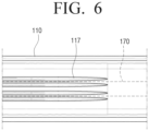
- FIG. 6 further illustrates, from a bottom view, part A of FIG. 5A
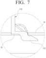
- FIG. 7 further illustrates, from an enlarged view, part B of FIG. 5A .
- FIG. 5A illustrates an arrangement of the sliding member 130 and the wire 170 in a state in which the door 20 is closed
- FIG. 5B illustrates an arrangement of the sliding member 130 and the wire 170 in a state in which the door 20 is opened.
- the case 110 includes a storing portion 113 and a drawing portion 114.
- the case 110 may store the wire 170 to prevent the wire 170 from being exposed to the outside, and the drawing portion 114 has a shape corresponding to the sliding member 130 so that the sliding member 130 slides to draw the wire 170.
- storing portion 113 stores the wire 170 drawn from the top surface of the body 10.
- the storing portion 113 determines a movement position of the wire 170 and includes a wire fixing portion limiting a moving length of the wire 170.
- the moving length of the wire 170 is limited by installing the wire fixing portion and this is to prevent the wire 170 from being entangled in the storing portion 113.
- the wire fixing portion includes protruding members 115a, 115b, and 115c protruding on an inner surface of the storing portion 113.
- the protruding members 115a, 115b, and 115c may be plural, and the wire fixing portion may include a wire fixing protrusion 116 protruding below a position corresponding to one of the protruding members 115a, 115b, and 115c.
- the wire fixing portion may have surfaces of the protruding members 115a, 115b, and 115c that are in contact with the wire, which are curved surfaces, to minimize friction with the wire. That is, the protruding members 115a, 115b, and 115c of the wire fixing portion may be formed in a cylindrical shape. Further, the protruding members 115a, 115b, and 115c of the wire fixing portion may include a roller (not shown) to minimize the friction even in a case in which the motion of the wire 170 occurs in the case 110.
- the wire 170 may be disposed in a zigzag shape above and below the plurality of protruding members 115a, 115b, and 115c.
- First to third protruding members 115a, 115b, and 115c may be sequentially disposed from a front surface.
- the wire 170 drawn from the top surface of the body 10 is disposed at upper ends of the first protruding member and third protruding member 115a and 115c, and may be disposed at a lower end of the second protruding member 115b.
- wire 170 is drawn to the outside of the case 110, since the wire 170 may be caught by the second protruding member 115b, it is possible to prevent the wire 170 from being disconnected because the wire 170 is drawn without any limitation and force is applied to the wire 170. Even if the maintenance of the wire 170 is performed, the protruding members 115a, 115b, and 115c may prevent the wire 170 from being drawn by a predetermined distance or more, thereby preventing the wire 170 inside the body 10 from being damaged.
- the wire fixing portion includes three protruding members 115a, 115b, and 115c as illustrated in FIG. 5A and FIG. 5B , in which case, the maximum drawing distance of the wire 170 is determined by a distance L3 from the second protruding member 115b to a position at which the wire is bent when the door 20 is closed.
- the wire 170 may be drawn approximately twice as long as the distance L3.
- the protruding members 115a, 115b, and 115c may be disposed so that the drawing distance of the wire 170 is sufficient, and in a case in which the wire 170 may be separated by the connector at the middle, the protruding members 115a, 115b, and 115c may be disposed by taking into account only the drawing distance of the sliding member 130.
- a protruding portion 117 may be provided in a length direction of the case 110 to be linearly in contact with the wire 170 inside the case 110.
- FIG. 6 which illustrates, through an enlarged bottom view, part A of FIG. 5A , an upper bottom of the case 110 has a comb shaped protruding portion 117.
- the wire 170 is in contact with the case 110, and the wire 170 is in contact with a tip of the protruding portion 117.
- a contact area is reduced and the friction between the wire 170 and the case 110 is reduced as compared to a case in which the wire 170 is directly in contact with the case 110. Since resistance is small during the movement of the wire 170 due to allowing a direction of the protruding portion 117 of the comb-shape to coincide with a movement direction of the wire 170, it may be possible to prevent the wire from being damaged due to the friction between the wire 170 and the case 110.
- FIG. 5B illustrates a coupled portion between the case 110 and top surface of the body 10 according to some embodiments of the present disclosure.
- the top surface of the body 10 has a coupling groove 15 and one end of the case 110 has the inserting protrusion 112 having a shape corresponding to the coupling groove 15.
- the inserting protrusion 112 of the case is hooked to the coupling groove 15.
- One end portion of the case 110 is hooked to the coupling groove 15 as described above, and the side surface of the case 110 is screwed to the body as described above.
- a case screw groove 111 which is on the side surface of the case is illustrated in FIG. 5A and FIG. 5B .
- the case screw groove 111 is disposed at a position corresponding to the body screw groove 11 protruding on the top surface of the body 10, and the body 10 and the side surface of the case 110 are screwed to the respective screw grooves 11 and 111 externally from the central portion of the body 10.
- door 20 performs an advance movement by the multi-joint hinge 30 being relaxed. Since the main door link 32 and the sub door link 34 are hinge-connected to the door fixing frame 36, they involve the rotary movement. Therefore, the door 20 simultaneously performs the advance and rotary movements.
- the sliding member 130 slides in the door direction from the wire cover unit 100 and is drawn by the advanced distance L1 of the door 20. Since the length of the sliding member 130 is determined by taking account into the movement distance L1 of the door 20, the wire 170 is not exposed between the sliding member 130 and the case 110. Since the wire 170 is not exposed, friction between an external object and the wire 170 may be reduced, and wear and damage of the wire 170 may be reduced.
- the storing portion of the case 110 keeps a sufficient length of wire 170 which may be moved by taking account into the drawn length of the wire 170, force pulling the wire 170 by the opened door 20, that is, tensile force applied to the wire 170 may be minimized. Therefore, a damage risk of the wire 170 may be reduced.
- the plurality of protruding members 115a, 115b, and 115c when the wire 170 moves in the case 110, the plurality of protruding members 115a, 115b, and 115c have the curved surface or are configured as the cylindrical roller, thereby reducing the friction between the plurality of protruding members 115a, 115b, and 115c and the wire 170 inside the case 110.
- the door 20 When the door 20 is fully opened, in some embodiments, the door 20 is opened as indicated by the dotted line of FIG. 3 .
- a predominantly opened position of the door 20 is determined according to a movement range of the multi-joint hinge 30.
- the sliding member 130 When the door 20 is fully opened and an angle between the opened surface of the body 10 and the door 20 is an obtuse angle, the sliding member 130 is bent. If the sliding member 130 is weak in softness, since sliding member 130 may be damaged, it is preferable that the sliding member 130 is formed of a soft material.
- the wire cover unit 100 includes the case 110, the sliding member 130, and the fixing bracket 150.
- the sliding member 130 and the fixing bracket 150 which are hingeably connected to each other are provided.
- the inserting protrusion 112 of the case 110 is inserted into the coupling groove 15 of the top surface of the body 10 and is hooked thereto.
- the body screw groove 11 protruding from the body 10 and a corresponding case screw groove 111 are aligned to coincide with each other, and the screw is coupled to the screw grooves 11 and 111 in an outward direction from the centre of the body 10.
- the sliding member 130 can be installed to protect the wire 170 drawn from the case 110.
- the wire 170 drawn from the case is inserted into the sliding member 130, and the sliding member 130 slides into the case 110 through the drawing portion 114. Thereafter, the fixing bracket 150 which is hingeably connected to the sliding member 130 is coupled to the door frame 36, thereby mounting the wire cover unit 100 in the built-in refrigerator 1. Thereafter, the wire 170 is connected through the wire connection terminal (harness).
- An operation of disassembling the wire cover unit 100 may be performed in the reverse order of the mounting operation for maintenance or replacement of the wire 170 provided in the built-in refrigerator 1.
- the wire cover unit 100 may be mounted in a device such as a built-in microwave oven, a built-in styler, or the like having a door 20 which includes a device requiring power such as a display or including a dial button requiring transmission and reception of signals.
- a device such as a built-in microwave oven, a built-in styler, or the like having a door 20 which includes a device requiring power such as a display or including a dial button requiring transmission and reception of signals.
- the wire cover unit 100 includes the sliding member 130 and the case 110, and the wire 170 may be drawn through the sliding member 130 in conjunction with the movement of the door 20 according to the motion of the multi-joint hinge 30.
- the external exposure of the wire 170 may be minimized, the damage risk due to the friction with the external object is reduced, and there is an advantage in that an appearance is good.
- the wire cover unit has the protruding members 115a, 115b, and 115c inside the case 110 and has the protruding portion 117 in the length direction of the case, the friction due to the movement of the wire 170 may be reduced and the damage risk due to the movement of the wire may also be reduced.
Landscapes
- Engineering & Computer Science (AREA)
- Mechanical Engineering (AREA)
- Chemical & Material Sciences (AREA)
- Combustion & Propulsion (AREA)
- Physics & Mathematics (AREA)
- Thermal Sciences (AREA)
- General Engineering & Computer Science (AREA)
- Refrigerator Housings (AREA)
Description
- The present disclosure relates to a built-in refrigerator, and more particularly, to a built-in refrigerator including a wire cover unit of which a portion is configured to move in a sliding manner to reduce friction of a wire due to an opening and closing of a door.
- In some refrigerators, wires may be drawn from the body of the refrigerator and connected to the inside of a door to supply power to electronic devices such as a display device, a control panel, and the like of the door and transmit and receive signals to and from the electronic devices.
- Since certain refrigerators provide an opening and closing function of the door by a hinge motion, a through hole is formed in the central portion of a rotary shaft and the wire is drawn from the through hole to supply the power to the door.
- In certain refrigerators, however, when the door is opened and closed by using a multi-joint hinge, the door is moved simultaneously with linear motion and a rotary motion. Thereby, as the door is opened and closed, the wire can be pulled otherwise introduce friction with surrounding structures at exposed portions of the wire.
- As a result, there the wire could be damaged and the sheath of the wire peeled off, and a core of the wire was exposed to the outside, which causes a risk of electric shock accident, and there was a problem in that an appearance was not good.
-
DE 693 23 392 T2 relates to a refrigerator with a door mounted dispenser supply mechanism.US 2013/212835 A1 relates to a hinge for a household appliance.US 2013/092802 A1 relates to a line extender/retractor.DE 20 2008 006133 A1 relates to a refrigerator/freezer.US 2014/210328 A1 relates to a home appliance.US 3,788,094 A relates to a refrigerator cabinet having a waterline retractor mechanism. - Exemplary embodiments of the present disclosure overcome the above disadvantages and other disadvantages not described above. Also, the present disclosure is not required to overcome the disadvantages described above, and an exemplary embodiment of the present disclosure may not overcome any of the problems described above.
- To address the above-discussed deficiencies, it is a primary object to provide a built-in refrigerator including a wire cover unit capable of minimizing a damage of a wire by reducing a friction occurring at the wire.
- In accordance with an aspect of the present invention, there is provided a built-in refrigerator according to
claim 1. Embodiments of the invention are set out in the dependent claims. - The hinge may be a multi-joint hinge, and the fixing bracket may be connected to the door through a portion which is adjacent to the door of the multi-joint hinge.
- The storing portion may include a wire fixing portion limiting a movement length of the wire.
- The wire fixing portion may include a protruding member protruding on an inner surface of the storing portion.
- A plurality of protruding members may be provided, and the wire may be disposed above and below the plurality of protruding members in a zigzag shape.
- The sliding member may be formed of a soft material.
- The body may include a coupling hole positioned in the top surface, and one end of the wire cover unit may include an inserting protrusion corresponding to a shape of the coupling hole, and the inserting protrusion and the coupling hole may be hooked to each other.
- The body may be screwed to the wire cover unit in an outward direction from a centre of the body.
- The body may include a body screw groove protruding from the body, the wire cover unit may include a cover screw groove in a side surface of the wire cover unit corresponding to the body screw groove, and a screw may be fastened to the body screw groove and the cover screw groove.
- Before undertaking the DETAILED DESCRIPTION below, it may be advantageous to set forth definitions of certain words and phrases used throughout this patent document: the terms "include" and "comprise", as well as derivatives thereof, mean inclusion without limitation; the term "or", is inclusive, meaning and/or; the phrases "associated with" and "associated therewith", as well as derivatives thereof, may mean to include, be included within, interconnect with, contain, be contained within, connect to or with, couple to or with, be communicable with, cooperate with, interleave, juxtapose, be proximate to, be bound to or with, have, have a property of, or the like.
- Definitions for certain words and phrases are provided throughout this patent document, those of ordinary skill in the art should understand that in many, if not most instances, such definitions apply to prior, as well as future uses of such defined words and phrases.
- For a more complete understanding of the present disclosure and its advantages, reference is now made to the following description taken in conjunction with the accompanying drawings, in which like reference numerals represent like parts:
-
FIG. 1 illustrates a perspective view of a built-in refrigerator including a wire cover unit according to the present disclosure; -
FIG. 2 illustrates a plan view of a door of a built-in refrigerator in a closed state, according to the present disclosure; -
FIG. 3 is a plan view illustrating a state in which the door of the built-in refrigerator including a wire cover unit according to the present disclosure is opened; -
FIG. 4 illustrates a perspective view of a wire cover unit according to the present disclosure; -
FIGS. 5A and 5B illustrate cross-sectional views of a wire cover unit and an upper portion of a body of the built-in refrigerator according to the present disclosure; -
FIG. 6 further illustrates, through a bottom view, part A shown inFIG. 5A ; and -
FIG. 7 further illustrates, through an enlarged cross-sectional view, part B shown inFIG. 5A . - FIGS. 1A through 7, discussed below, and the various embodiments used to describe the principles of the present disclosure in this patent document are by way of illustration only and should not be construed in any way to limit the scope of the disclosure, which is defined by the claims. Those skilled in the art will understand that the principles of the present disclosure may be implemented in any suitably arranged system or device.
- Hereinafter, diverse exemplary embodiments of the present disclosure will be described with reference to the accompanying drawings. Throughout the accompanying drawings, similar components will be denoted by similar reference numerals.
- Terms used in the present disclosure may be used only in order to describe specific exemplary embodiments rather than restricting the scope of other exemplary embodiments. Singular forms may include plural forms unless the context clearly indicates otherwise. Terms used in the present specification including technical and scientific terms have the same meanings as those that are generally understood by those skilled in the art to which the present disclosure pertains. Terms defined by a general dictionary among terms used in the present disclosure may be interpreted as meaning that are the same as or similar to meanings within a context of the related art, and are not interpreted as ideal or excessively formal meaning unless clearly defined in the present disclosure. In some cases, terms may not be interpreted to exclude exemplary embodiments of the present disclosure even though they are defined in the present disclosure.
- Hereinafter, a configuration of a built-in refrigerator according to certain embodiments of the present disclosure will be described with reference to the accompanying drawings.
-
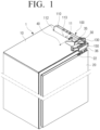
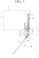
FIG. 1 illustrates a perspective view of a built-in refrigerator including a wire cover unit according to at least one exemplary embodiment of the present disclosure,FIG. 2 illustrates a plan view of a door of a built-inrefrigerator 1 including a wire cover unit according to an exemplary embodiment of the present disclosure in a closed state, andFIG. 3 illustrates a plan view of a door of a built-in refrigerator including a wire cover unit according to certain embodiments of the present disclosure, in an opened state. - Referring to
FIG. 1 , a built-inrefrigerator 1 according to the present invention includes abody 10, adoor 20, ahinge 30, and awire cover unit 100. - The built-in
refrigerator 1 may be installed on a wall surface or in a space provided between the kitchen cabinetry. Thebody 10 includes an opened one surface and includes storage space therein. - The
door 20 is, in some embodiments, connected to one corner of the opened surface of thebody 10 by thehinge 30. Thedoor 20 may include electronic devices (not shown) such as a display, a temperature control button, and the like, and awire passing hole 22. The wire for supplying power to the electronic device or transmitting and receiving signals to and from the electronic device supplies the power or transmits and receives the signals to and from the electronic device through thewire passing hole 22. - The
hinge 30 may be a multi-joint hinge. According to certain embodiments,body frame 35 and adoor frame 36 of thehinge 30 are coupled to thebody 10 and thedoor 20, respectively. Since the built-inrefrigerator 1 can be arranged on the wall surface or in the space between the kitchen cabinetry, a side surface of the built-inrefrigerator 1 may have almost no free space. Therefore, when a rotary door hinge performing only a rotary motion is used, an outer portion of the door may strike or impinge upon the kitchen cabinetry or the wall surface. - In order to solve the above-mentioned problem, it may be preferable that the
hinge 30 connecting thebody 10 and thedoor 20 of the built-inrefrigerator 1 be a multi-joint hinge. - The multi-joint may simultaneously perform a forward motion and a rotary motion. That is, when the
door 20 is opened, thedoor 20 may move to a front of thebody 10 and perform the rotary motion at the same time. Since thedoor 20 is operated to be opened while moving to the front of thebody 10, the outer portion of thedoor 20 may avoid the striking or otherwise impinging upon the kitchen cabinetry or the wall surface. - The
wire cover unit 100 includes acase 110, a slidingmember 130, and afixing bracket 150. - The
case 110 includes a space in which the wire drawn from thebody 10 is positioned and is coupled to a top surface of thebody 10. In order to couple thecase 110 to the top surface of thebody 10 without using separate equipment, one end of thecase 110 is hooked to the top surface of thebody 10. Acoupling groove 15 of the top surface of thebody 10 and an insertingprotrusion 112 of a rear surface portion of the case are hooked to each other to fix one end of thecase 110 to the top surface of thebody 10. - The top surface of the
body 10 and a side surface of thecase 110 are connected to each other by one or more screws. It may be undesirable and/or difficult for the built-inrefrigerator 1 to incorporate a screw which fastens to thecase 110 from a side which is adjacent to the wall surface. The reason is because depending on the overall profile of built-in refrigerator and the installation site, the gap between the side surface of thecase 110 and a wall surface may be very narrow. Therefore, ascrew 40 may fastened to abody screw groove 11 in a direction from the centre of thebody 10 toward the wall surface. - A portion of the wire drawn from the top surface of the
body 10 and positioned in thecase 110 is enclosed by a slidingmember 130. The slidingmember 130 includes a space in which the wire is mounted. - The sliding
member 130 is connected to the fixingbracket 150 by a rotatable hinge 152 (seeFIG. 2 ) at one end thereof, and includes an opening 131 (seeFIG. 4 ) so that the wire is drawn in a door direction. The wire drawn from thebody 10 may be led into the other end of the slidingmember 130 by the slidingmember 130. - According to some embodiments that are useful for understanding the invention, the sliding
member 130 is coupled to thedoor 20 or according to the invention the slidingmember 130 is coupled to the fixingbracket 150 attached to thedoor 20 through thehinge 152. If there is nohinge 152 when thedoor 20 is opened from thebody 10 and is rotated, the sliding member may be bent. In such cases, stress may be repeatedly applied to the slidingmember 130 from the opening and closing ofdoor 20, and the slidingmember 130 may be subject to fatigue failure. Thus, one end of the slidingmember 130 may be hingeably coupled to thedoor 20 or, in accordance with the invention, coupled to the fixingbracket 150 to be rotatable. Further, since the slidingmember 130 may be bent when thedoor 20 is fully opened, an ABS (acrylonitrile-butadiene-styrene) resin or similarly flexible material may be used. - The length of the sliding
member 130 may be determined depending on an advancing distance of thedoor 20. That is, according to some embodiments, the length of the slidingmember 130 is determined to be longer than the advancing distance of thedoor 20 so that the wire is not exposed to the outside of thecase 110. - The fixing
bracket 150 is coupled to thedoor frame 36 of themulti-joint hinge 30 and is connected to thedoor 20. The fixingbracket 150 is hingeably connected to the slidingmember 130. Therefore, when thedoor 20 of the built-in refrigerator is opened, the slidingmember 130 may move in conjunction with a forward motion of thedoor 20. The fixingbracket 150 includes a wire guide that guides the wire drawn from theopening 131 of the slidingmember 130 to awire connection terminal 172 which is adjacent to the door or in other examples that are useful for understanding the invention to thewire passing hole 22 of thedoor 20. - The wire may minimize its motion through the wire guide. Such a wire guide guides the wire to the
wire passing hole 22 of thedoor 20 or, in accordance with the invention, to thewire connection terminal 172 which is adjacent to thedoor 20. - The
wire cover unit 100 includes the fixingbracket 150. According to other embodiments that are useful for understanding the invention, the fixingbracket 150 may be omitted. In a case in which the fixingbracket 150 is omitted, the slidingmember 130 may be hingeably connected to thedoor frame 36 or may be hingeably connected to thedoor 20, and thewire passing hole 22 may be formed to be adjacent to the hinge. - A structure of the multi-joint hinge according to certain embodiments of this disclosure will be now described and an opening and closing operation of the
door 20 of the built-in refrigerator will be then described with reference toFIGS. 2 and3 . - According to certain embodiments, the
multi-joint hinge 30 includes a plurality oflinks FIG. 3 , themulti-joint hinge 30 includes amain body link 31, amain door link 32, asub body link 33, and asub door link 34. Further, themulti-joint hinge 30 further includes abody frame 35 attached to thebody 10 and adoor fixing frame 36 attached to thedoor 20. - One end of the
main body link 31 of themulti-joint hinge 30 is hingeably connected to thebody frame 35 and the other end of themain body link 31 is connected to one end of themain door link 32. The other end of themain door link 32 is hingeably connected to thedoor frame 36. Although it is described in the drawing of the present disclosure that the other end of themain door link 32 is hingeably connected to thedoor frame 36, the other end of themain door link 32 may be configured to slide on thedoor frame 36. - According to certain embodiments, the multi-joint hinge may include only the
main body link 31 and themain door link 32, and can present a problem that the opening and closing path of the door is varies. According to some embodiments, the opening and closing path can be limited by attaching thesub body link 33 and thesub door link 34. One end of thesub body link 33 is coupled to thebody frame 35 of thebody 10 and the other end of thesub body link 33 hingeably connected to the central portion of thesub door link 34. One end of thesub door link 34 may be hingeably connected to the central portion of themain body link 31 to limit a path of themain body link 31. The other end of thesub door link 34 is hingeably coupled to thedoor frame 36. - As described above, according to some embodiments of the present disclosure, the
main body link 31, themain door link 32, thesub body link 33, and thesub door link 34 of themulti-joint hinge 30 can be organically coupled to each other to allow simultaneous forward and rotational movement along defined path(s). With the organic coupling between the respective links, themulti-joint hinge 30 may move thedoor 20 forward and rotate thedoor 20 at the same time while limiting a movement direction of thedoor 20 to one. By themulti-joint hinge 30, it is possible for thedoor 20 to avoid interference with the wall surface or the furniture closet when thedoor 20 is opened. - Referring to the illustration of certain exemplary embodiments provided by
FIG. 2 , when thedoor 20 closes the inside of thebody 10, themulti-joint hinge 30 is contracted with each other, and thedoor 20 and an opened one surface of thebody 10 face each other. According to certain embodiments, in the case in which thedoor 20 is closed, an exposed length of the slidingmember 130 may at its shortest. In this case, most of the slidingmember 130 remains in thecase 110. - Referring to
FIG. 3 , according to some embodiments, when thedoor 20 is opened, the links of themulti-joint hinge 30 are relaxed and thedoor 20 simultaneously performs the forward and rotary motions. Therefore, the distance between thehinge 152 of one end of the slidingmember 130 and a portion from which the slidingmember 130 of thecase 110 is drawn is increased. That is, the slidingmember 130 slides from thecase 110 and is drawn to the outside. Since the advancing distance, a rotary direction, and a movement direction of thedoor 20 are limited by themulti-joint hinge 30, the distance of the slidingmember 130 drawn from thecase 110 is also limited. Since, according to certain embodiments, the length of the slidingmember 130 is determined to be larger than a distance at which the slidingmember 130 is maximally drawn, the entirety of the slidingmember 130 need not be drawn to the outside of thecase 110. - In
FIG. 3 , a portion indicated by a dotted line illustrates a case in which thedoor 20 is opened by 90° or more based on the opened surface of thebody 10. In this case, the slidingmember 130 may be bent, and the slidingmember 130 may be formed of a soft material such as ABS, a rubber, or the like to prevent the slidingmember 130 from being damaged due to the bending. -
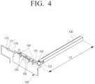
FIG. 4 is a perspective view illustrating awire cover unit 100 according to an exemplary embodiment of the present disclosure. - Referring to
FIG. 4 , according to certain embodiments, one end of the slidingmember 130 is hingeably connected to the fixingbracket 150. Theopening 131 may be formed in a side surface of the sliding member at one end of the slidingmember 130 and thewire 170 is drawn from theopening 131 of the slidingmember 130. - The fixing
bracket 150 includes awire guide 151, and thewire guide 151 guides the wire drawn from theopening 131 to thewire connection terminal 172 which is adjacent to thedoor 20 or in other examples that are useful for understanding the invention to the wire passing hole 22 (seeFIG. 1 ) included in the door. Awire connection terminal 171 which is adjacent to the slidingmember 130 and is connectable to thewire connection terminal 172 which is adjacent to thedoor 20 may be included. Thewire connection terminals - The
wire guide 151 includes a pair of protrudingpieces 153 and two ormore fixing protrusions 154. - The pair of protruding
pieces 153 is disposed on the fixingbracket 150 to face each other. In this case, the wire is disposed between the pair of protrudingpieces 153. At least two or more fixingprotrusions 154 fixing thewire 170 disposed between the pair of protrudingpieces 153 is further disposed on the fixingbracket 150. - The
wire 170 drawn from theopening 131 of the slidingmember 130 is guided to thewire connection terminal 172 which is adjacent to thedoor 20 or in other examples that are useful for understanding the invention to thewire passing hole 22 by the pair of protrudingpieces 153. In this case, since thewire 170 may be moved when thedoor 20 is opened and closed, a fixing member for fixing thewire 170 is required. According to certain embodiments the present disclosure, as the fixing member for fixing the wire, the fixingprotrusions 154 may be used. A plurality of fixingprotrusions 154 are disposed on the fixingbracket 150 and thewire 170 is disposed in a zigzag shape so as to be caught by the plurality of fixingprotrusions 154, thereby limiting a motion of thewire 170 in a planar direction. - According to certain embodiments as disclosed herein,
wire guide 151 may haveauxiliary protrusions 155 protruding from the protrudingpieces 153. Theauxiliary protrusions 155 may limit vertical motion of thewire 170. As described above, thewire guide 151 may have a plurality of protrudingpieces 153, the fixingprotrusions 154, and the like to fix thewire 170 to a top surface of the fixingbracket 150. The fixing member for fixing is not limited to the protrudingpieces 153, the fixingprotrusion 154, theauxiliary protrusion 155, or the like, and may include a hook capable of fitting thewire 170, a through-type member attached to the fixingbracket 150 and enclosing the wire, and the like. - According to certain embodiments of the present disclosure, a length L2 of the sliding
member 130 may be determined in consideration of an installation position of the case and the advancing distance of thedoor 20. According to certain embodiments, it is desirable that length L2 of the slidingmember 130 be determined to have a margin in which thewire 170 may move so that thewire 170 is not bent inside thecase 110 at a position at which the slidingmember 130 is retracted, such as when thedoor 20 is closed. Further, according to some embodiments, the length of the sliding member is determined to be longer than the maximum advancing distance L1 (seeFIG. 3 ) of thedoor 20 so that a portion of the slidingmember 130 is disposed to be within the drawn portion of thecase 110 even at the maximum advancing distance of thedoor 20, when thedoor 20 is opened. -
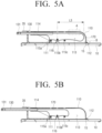
FIGS. 5A and 5B illustrate cross-sectional views of an upper portion of thewire cover unit 100 and thebody 10 of the built-inrefrigerator 1 according to certain exemplary embodiments of the present disclosure,FIG. 6 further illustrates, from a bottom view, part A ofFIG. 5A , andFIG. 7 further illustrates, from an enlarged view, part B ofFIG. 5A . - Referring to
FIG. 5A and 5B , in some embodiments, thecase 110 of thewire cover unit 110 and the top surface of thebody 10 are coupled to each other.FIG. 5A illustrates an arrangement of the slidingmember 130 and thewire 170 in a state in which thedoor 20 is closed andFIG. 5B illustrates an arrangement of the slidingmember 130 and thewire 170 in a state in which thedoor 20 is opened. - According to the present disclosure, the
case 110 includes a storingportion 113 and adrawing portion 114. Thecase 110 may store thewire 170 to prevent thewire 170 from being exposed to the outside, and thedrawing portion 114 has a shape corresponding to the slidingmember 130 so that the slidingmember 130 slides to draw thewire 170. - According to the present invention, storing
portion 113 stores thewire 170 drawn from the top surface of thebody 10. The storingportion 113 determines a movement position of thewire 170 and includes a wire fixing portion limiting a moving length of thewire 170. The moving length of thewire 170 is limited by installing the wire fixing portion and this is to prevent thewire 170 from being entangled in the storingportion 113. The wire fixing portion includes protrudingmembers portion 113. The protrudingmembers wire fixing protrusion 116 protruding below a position corresponding to one of the protrudingmembers members members members wire 170 occurs in thecase 110. - According to some embodiments, the
wire 170 may be disposed in a zigzag shape above and below the plurality of protrudingmembers members wire 170 drawn from the top surface of thebody 10 is disposed at upper ends of the first protruding member and third protrudingmember member 115b. According to someembodiments wire 170 is drawn to the outside of thecase 110, since thewire 170 may be caught by the second protrudingmember 115b, it is possible to prevent thewire 170 from being disconnected because thewire 170 is drawn without any limitation and force is applied to thewire 170. Even if the maintenance of thewire 170 is performed, the protrudingmembers wire 170 from being drawn by a predetermined distance or more, thereby preventing thewire 170 inside thebody 10 from being damaged. - According to some embodiments, the wire fixing portion includes three protruding
members FIG. 5A and FIG. 5B , in which case, the maximum drawing distance of thewire 170 is determined by a distance L3 from the second protrudingmember 115b to a position at which the wire is bent when thedoor 20 is closed. Thewire 170 may be drawn approximately twice as long as the distance L3. Therefore, when the maintenance of thewire 170 is required, in a case in which thewire 170 is separated or is not separated by a connector inside thedoor 20 or thebody 10, the protrudingmembers wire 170 is sufficient, and in a case in which thewire 170 may be separated by the connector at the middle, the protrudingmembers member 130. - In embodiments in which the
wire 170 and the inside of thecase 110 are in contact with each other, in order to minimize the friction between thewire 170 and thecase 110, a protrudingportion 117 may be provided in a length direction of thecase 110 to be linearly in contact with thewire 170 inside thecase 110. Referring toFIG. 6 , which illustrates, through an enlarged bottom view, part A ofFIG. 5A , an upper bottom of thecase 110 has a comb shaped protrudingportion 117. According to some embodiments, thewire 170 is in contact with thecase 110, and thewire 170 is in contact with a tip of the protrudingportion 117. Therefore, a contact area is reduced and the friction between thewire 170 and thecase 110 is reduced as compared to a case in which thewire 170 is directly in contact with thecase 110. Since resistance is small during the movement of thewire 170 due to allowing a direction of the protrudingportion 117 of the comb-shape to coincide with a movement direction of thewire 170, it may be possible to prevent the wire from being damaged due to the friction between thewire 170 and thecase 110. -
FIG. 5B illustrates a coupled portion between thecase 110 and top surface of thebody 10 according to some embodiments of the present disclosure. Referring toFIG. 7 , which illustrates an enlarged view of the coupled portion according to certain embodiments, the top surface of thebody 10 has acoupling groove 15 and one end of thecase 110 has the insertingprotrusion 112 having a shape corresponding to thecoupling groove 15. The insertingprotrusion 112 of the case is hooked to thecoupling groove 15. One end portion of thecase 110 is hooked to thecoupling groove 15 as described above, and the side surface of thecase 110 is screwed to the body as described above. Acase screw groove 111 which is on the side surface of the case is illustrated inFIG. 5A and FIG. 5B . Thecase screw groove 111 is disposed at a position corresponding to thebody screw groove 11 protruding on the top surface of thebody 10, and thebody 10 and the side surface of thecase 110 are screwed to therespective screw grooves body 10. - According to the invention, the drawing
portion 114 is utilized as a passage through which the slidingmember 130 is drawn from and led to the outside of thecase 110. Even in the case in which thedoor 20 is closed, the drawingportion 114 may have a sufficient length so that the slidingmember 130 is not exposed. - Hereinafter, an operation of the built-in
refrigerator 1 according to an exemplary embodiment of the present disclosure will be described with reference to the accompanying drawings. - According to certain embodiments, built-in
refrigerator 1 is stored in a cabinetry or is installed in a refrigerator storage space of the wall surface. When a strictly rotary hinge, is used in the built-inrefrigerator 1, wheredoor 20 is fully opened, interference between the wall surface or the furniture closet and a movement path of thedoor 20 occurs, thereby causing a case in which thedoor 20 is not fully opened. - Accordingly, the
door 20 of the built-inrefrigerator 1 may be connected to thebody 10 by themulti-joint hinge 30. Even in the case of the rotary hinge performing only a general rotary motion, there may be movement and exposure of the wire. However, to clearly illustrate features of thewire cover unit 100 of the built-inrefrigerator 1 according to certain embodiments of the present disclosure, the operation of the built-inrefrigerator 1 thedoor 20 and thebody 10 are connected to each other by themulti-joint hinge 30 as illustrated in the drawings. - A state in which the
door 20 of the built-inrefrigerator 1 is closed will be described with reference toFIGS. 1 ,2 ,5A and 5B . - According to some embodiments,
links multi-link hinge 30 are contracted to each other. Thewire 170 drawn from the top surface of thebody 10 of the built-inrefrigerator 1 is stored in the storingportion 113 of thecase 110, and a portion of the storedwire 170 is enclosed by the slidingmember 130 that slides on thedrawing portion 114 of thecase 110. Thewire 170 may be drawn through theopening 131 in a door direction of the slidingmember 130, and the drawnwire 170 is guided to thewire passing hole 22 of thedoor 20 along the guidance of the fixingbracket 150. Thewire 170 may be connected to an electronic device through thewire passing hole 22, and may supply power to the electronic device such as a display, a light apparatus dial, a lighting of the dial, or the like which is in thedoor 20, or transmit and receive signals according to an operation of the display or the dial with a controller (not shown). - As illustrated in
FIG. 5A , according to some embodiments, when thedoor 20 is closed, most of the slidingmember 130 is positioned inside thecase 110. Thewire 170 is stored in the storingportion 113 of thecase 110, and the protrudingmembers wire 170 or entangling between the wires. Since the protrudingmembers wire 170 according to the opening and closing of thedoor 20 and only thewire 170 of the limited length moves, the protrudingmembers wire 170. - A process of opening the
door 20 of the built-inrefrigerator 1 and a state in which thedoor 20 of the built-inrefrigerator 1 is opened, according to certain embodiments of the present disclosure will be described with reference toFIGS. 1 ,3 ,5A and 5B . - If the
door 20 is opened, themulti-joint hinge 30 starts to be relaxed. Since themulti-joint hinge 30 has therespective links door 20 is determined as described above. That is, thedoor fixing frame 36 of themulti-joint hinge 30 has one movement path based on thebody frame 35. - According to certain embodiments,
door 20 performs an advance movement by themulti-joint hinge 30 being relaxed. Since themain door link 32 and thesub door link 34 are hinge-connected to thedoor fixing frame 36, they involve the rotary movement. Therefore, thedoor 20 simultaneously performs the advance and rotary movements. - According to some embodiments, when the
door 20 advances, the slidingmember 130 slides in the door direction from thewire cover unit 100 and is drawn by the advanced distance L1 of thedoor 20. Since the length of the slidingmember 130 is determined by taking account into the movement distance L1 of thedoor 20, thewire 170 is not exposed between the slidingmember 130 and thecase 110. Since thewire 170 is not exposed, friction between an external object and thewire 170 may be reduced, and wear and damage of thewire 170 may be reduced. - Further, since the storing portion of the
case 110 keeps a sufficient length ofwire 170 which may be moved by taking account into the drawn length of thewire 170, force pulling thewire 170 by the openeddoor 20, that is, tensile force applied to thewire 170 may be minimized. Therefore, a damage risk of thewire 170 may be reduced. - According to certain embodiments, when the
wire 170 moves in thecase 110, the plurality of protrudingmembers members wire 170 inside thecase 110. - When the
door 20 is fully opened, in some embodiments, thedoor 20 is opened as indicated by the dotted line ofFIG. 3 . A predominantly opened position of thedoor 20 is determined according to a movement range of themulti-joint hinge 30. When thedoor 20 is fully opened and an angle between the opened surface of thebody 10 and thedoor 20 is an obtuse angle, the slidingmember 130 is bent. If the slidingmember 130 is weak in softness, since slidingmember 130 may be damaged, it is preferable that the slidingmember 130 is formed of a soft material. - Hereinafter, an operation of mounting and separating the
wire cover unit 110 on and from the built-inrefrigerator 1 according to certain embodiments of the present disclosure will be described. - In some embodiments, the
wire cover unit 100 includes thecase 110, the slidingmember 130, and the fixingbracket 150. The slidingmember 130 and the fixingbracket 150 which are hingeably connected to each other are provided. - First, the
wire 170 is disposed on the protrudingmembers case 110 in the zigzag shape, and the margin taking account into the movement length of thewire 170 is stored in the storingportion 113. A portion of the storedwire 170 is disposed to be exposed to the outside through the drawingportion 114. - Thereafter, in some embodiments, the inserting
protrusion 112 of thecase 110 is inserted into thecoupling groove 15 of the top surface of thebody 10 and is hooked thereto. Thebody screw groove 11 protruding from thebody 10 and a correspondingcase screw groove 111 are aligned to coincide with each other, and the screw is coupled to thescrew grooves body 10. - If the
case 110 and thebody 10 are fixed, the slidingmember 130 can be installed to protect thewire 170 drawn from thecase 110. - According to certain embodiments, the
wire 170 drawn from the case is inserted into the slidingmember 130, and the slidingmember 130 slides into thecase 110 through the drawingportion 114. Thereafter, the fixingbracket 150 which is hingeably connected to the slidingmember 130 is coupled to thedoor frame 36, thereby mounting thewire cover unit 100 in the built-inrefrigerator 1. Thereafter, thewire 170 is connected through the wire connection terminal (harness). - An operation of disassembling the
wire cover unit 100 may be performed in the reverse order of the mounting operation for maintenance or replacement of thewire 170 provided in the built-inrefrigerator 1. - Although the
wire cover unit 100 according to an exemplary embodiment of the present disclosure is described as being mounted in the built-inrefrigerator 1, thewire cover unit 100 may be mounted in a device such as a built-in microwave oven, a built-in styler, or the like having adoor 20 which includes a device requiring power such as a display or including a dial button requiring transmission and reception of signals. - As described above, in some embodiments, the
wire cover unit 100 includes the slidingmember 130 and thecase 110, and thewire 170 may be drawn through the slidingmember 130 in conjunction with the movement of thedoor 20 according to the motion of themulti-joint hinge 30. Thereby, the external exposure of thewire 170 may be minimized, the damage risk due to the friction with the external object is reduced, and there is an advantage in that an appearance is good. - Further, since, according to some embodiments, the wire cover unit has the protruding
members case 110 and has the protrudingportion 117 in the length direction of the case, the friction due to the movement of thewire 170 may be reduced and the damage risk due to the movement of the wire may also be reduced. - Although the present disclosure has been described with exemplary embodiments, various changes and modifications may be suggested to one skilled in the art that fall within the scope of the appended claims.
Claims (7)
- A built-in refrigerator (1) comprising:a body (10);a door (20) configured to open and close an inside of the body (10);a hinge (30) configured to connect the body (10) with the door (20); anda wire cover unit (100) configured to guide a wire (170) drawn from the body (10) while a portion thereof slides according to an opening and closing of the door (20),wherein the wire cover unit (100) includes:a case (110) coupled to a top surface of the body (10) and configured to accommodate the wire (170) drawn from the body (10);a sliding member (130) configured to slide linearly from an inside of the case (110) to be drawn to an outside of the case (110), and to enclose a portion of the wire (170);a fixing bracket (150) configured to be hingeably connected to the sliding member (130) and coupled to the door (20); anda plurality of protruding portions (117) which are linearly in contact with the wire (170) in a length direction of the wire (170),wherein the case (110) includes:an accommodating portion (113) formed by a space of the case (110) and configured to accommodate the wire (170); anda drawing portion (114) having a shape corresponding to the sliding member (130) and configured to linearly guide the sliding member (130) when the sliding member (130) is drawn through the drawing portion (114) according to the opening or closing of the door (20),wherein the drawing portion (114) is used as a passage through which the sliding member (130) is drawn into and out of the case (110),wherein the fixing bracket (150) includes a wire guide (151) that guides the wire (170) drawn from the sliding member (130) to a wire connection terminal (172) which is adjacent to the door (20),wherein the wire guide (151) includes:a pair of protruding pieces (153) disposed to face each other; andat least two or more fixing protrusions (154) configured to hold the wire (170) disposed between the pair of protruding pieces (153), andwherein one end of the wire cover unit (100) is hooked to a top surface of the body (10), and a portion of a side surface of the wire cover unit (100) is screwed to the body (10).
- The built-in refrigerator (1) of claim 1, wherein the hinge (30) is a multi-joint hinge, and
the fixing bracket (150) is connected to the door (20) through a portion which is adjacent to the door (20) of the multi-joint hinge. - The built-in refrigerator (1) of claim 1, wherein the accommodating portion (113) includes a wire fixing portion limiting a movement length of the wire (170), and
the wire fixing portion includes a protruding member (115a, 115b, 115c) protruding on an inner surface of the accommodating portion (113). - The built-in refrigerator (1) of claim 3, wherein a plurality of protruding members (115a, 115b, 115c) are provided, and
the wire (170) is disposed above and below the plurality of protruding members (115a, 115b, 115c) in a zigzag shape. - The built-in refrigerator (1) of any one of the preceding claims, wherein the body (10) includes a coupling hole (15) positioned in the top surface,one end of the wire cover unit (100) includes an inserting protrusion (112) corresponding to a shape of the coupling hole (15), andthe inserting protrusion (112) and the coupling hole (15) are hooked to each other.
- The built-in refrigerator (1) of claim 5, wherein the body (10) is screwed to the wire cover unit (100) in an outward direction from a centre of the body (10).
- The built-in refrigerator (1) of claim 5 or 6, wherein the body (10) includes a body screw groove (11) protruding from the body (10),the wire cover unit (100) includes a cover screw groove (111) in a side surface of the wire cover unit (100) corresponding to the body screw groove (11), anda screw is fastened to the body screw groove (11) and the cover screw groove (111).
Applications Claiming Priority (1)
| Application Number | Priority Date | Filing Date | Title |
|---|---|---|---|
| KR1020170000907A KR102253487B1 (en) | 2017-01-03 | 2017-01-03 | A built-in refrigerator including a wire cover unit |
Publications (3)
| Publication Number | Publication Date |
|---|---|
| EP3343152A1 EP3343152A1 (en) | 2018-07-04 |
| EP3343152B1 true EP3343152B1 (en) | 2025-07-09 |
| EP3343152C0 EP3343152C0 (en) | 2025-07-09 |
Family
ID=60811866
Family Applications (1)
| Application Number | Title | Priority Date | Filing Date |
|---|---|---|---|
| EP17210033.1A Active EP3343152B1 (en) | 2017-01-03 | 2017-12-22 | Built-in refrigerator including wire cover unit |
Country Status (4)
| Country | Link |
|---|---|
| US (2) | US10563904B2 (en) |
| EP (1) | EP3343152B1 (en) |
| KR (1) | KR102253487B1 (en) |
| CN (1) | CN108266954B (en) |
Families Citing this family (31)
| Publication number | Priority date | Publication date | Assignee | Title |
|---|---|---|---|---|
| EP3526431A4 (en) | 2016-10-17 | 2020-06-10 | Whirlpool Corporation | HINGE ASSEMBLY |
| US10544983B2 (en) | 2017-01-03 | 2020-01-28 | Samsung Electronics Co., Ltd. | Refrigerator |
| KR102412060B1 (en) | 2017-04-26 | 2022-06-23 | 엘지전자 주식회사 | Refrigerator |
| US11091943B2 (en) * | 2018-12-29 | 2021-08-17 | Whirlpool Corporation | Articulating wire chase for use with an articulating hinge for an appliance door |
| CN112444030B (en) * | 2019-08-28 | 2022-11-08 | 青岛海尔电冰箱有限公司 | Refrigerator with wiring module |
| CN117661944A (en) | 2020-07-30 | 2024-03-08 | Lg电子株式会社 | Multi-joint connecting rod hinge and refrigerator including the multi-joint connecting rod hinge |
| KR20220022225A (en) | 2020-08-18 | 2022-02-25 | 엘지전자 주식회사 | Refrigerator |
| US11725443B2 (en) * | 2020-12-07 | 2023-08-15 | Haier Us Appliance Solutions, Inc. | Linear hinge assembly for an appliance |
| KR20220085383A (en) | 2020-12-15 | 2022-06-22 | 엘지전자 주식회사 | Refrigerator |
| KR20220085385A (en) | 2020-12-15 | 2022-06-22 | 엘지전자 주식회사 | Refrigerator |
| KR20220085384A (en) | 2020-12-15 | 2022-06-22 | 엘지전자 주식회사 | Refrigerator |
| KR20220099332A (en) * | 2021-01-06 | 2022-07-13 | 엘지전자 주식회사 | Refrigerator |
| KR20220099329A (en) | 2021-01-06 | 2022-07-13 | 엘지전자 주식회사 | Refrigerator |
| KR20220099330A (en) | 2021-01-06 | 2022-07-13 | 엘지전자 주식회사 | Refrigerator |
| KR20220099328A (en) * | 2021-01-06 | 2022-07-13 | 엘지전자 주식회사 | Refrigerator |
| KR20230038048A (en) * | 2021-09-10 | 2023-03-17 | 삼성전자주식회사 | Refrigerator |
| CN116222064B (en) * | 2021-12-03 | 2025-11-11 | 青岛海尔电冰箱有限公司 | Refrigerator with take-up structure |
| CN116294344B (en) * | 2021-12-03 | 2025-09-09 | 青岛海尔电冰箱有限公司 | Refrigerator with wiring module |
| CN116222066B (en) * | 2021-12-03 | 2025-10-17 | 青岛海尔电冰箱有限公司 | Refrigerator with winding device |
| WO2023098200A1 (en) * | 2021-12-03 | 2023-06-08 | 青岛海尔电冰箱有限公司 | Refrigerator with wiring module |
| CN116222067A (en) * | 2021-12-03 | 2023-06-06 | 青岛海尔电冰箱有限公司 | Refrigerator with retractable cable routing module |
| CN116222069B (en) * | 2021-12-03 | 2025-09-09 | 青岛海尔电冰箱有限公司 | Refrigerator with wiring assembly assembled with refrigerator body |
| AT525246B1 (en) * | 2021-12-21 | 2023-02-15 | Blum Gmbh Julius | Fitting for the movable mounting of a pivoting element |
| CN117128685A (en) * | 2022-05-20 | 2023-11-28 | 青岛海尔电冰箱有限公司 | refrigerator |
| KR20240018273A (en) | 2022-08-02 | 2024-02-13 | 엘지전자 주식회사 | Cooking appliance |
| KR20240018266A (en) | 2022-08-02 | 2024-02-13 | 엘지전자 주식회사 | Cooking appliance |
| WO2024029727A1 (en) * | 2022-08-03 | 2024-02-08 | 삼성전자주식회사 | Refrigerator |
| KR20240113135A (en) * | 2023-01-13 | 2024-07-22 | 삼성전자주식회사 | Refrigerator |
| CN119998609A (en) * | 2023-01-13 | 2025-05-13 | 三星电子株式会社 | refrigerator |
| CN116182458B (en) * | 2023-03-08 | 2024-10-29 | 海信冰箱有限公司 | Built-in refrigerator |
| WO2024237525A1 (en) * | 2023-05-12 | 2024-11-21 | 삼성전자주식회사 | Electronic device comprising discontinuous part for shifting parasitic resonance frequency |
Family Cites Families (39)
| Publication number | Priority date | Publication date | Assignee | Title |
|---|---|---|---|---|
| US3396282A (en) * | 1965-08-20 | 1968-08-06 | Rca Corp | Time delay circuit employing logic gate |
| GB1347656A (en) * | 1972-02-11 | 1974-02-27 | Messerschmitt Boelkow Blohm | Guides for electrical cables |
| US3788094A (en) * | 1972-12-01 | 1974-01-29 | Gen Motors Corp | Waterline retractor for refrigerator cabinet |
| JPH02146490A (en) * | 1988-11-28 | 1990-06-05 | Hitachi Ltd | Refrigerator |
| US5263509A (en) * | 1992-11-12 | 1993-11-23 | General Electric Company | Refrigerator with door mounted dispenser supply mechanism |
| KR0136613Y1 (en) | 1995-08-19 | 1999-03-20 | 구자홍 | Wire connection structure of a refrigerator |
| US5787724A (en) * | 1997-06-04 | 1998-08-04 | Maytag Corporation | Dispensing assembly for top mount refrigerator |
| US5941619A (en) * | 1997-09-24 | 1999-08-24 | White Consolidated Industries, Inc. | Electrical connector for a refrigerator and method of installing |
| US20030090182A1 (en) * | 2001-11-14 | 2003-05-15 | Johnson Kristianne E. | Interchangeable customized bezel |
| US7623115B2 (en) * | 2002-07-27 | 2009-11-24 | Sony Computer Entertainment Inc. | Method and apparatus for light input device |
| US20060017361A1 (en) * | 2004-07-23 | 2006-01-26 | Robert Rendel | Hinge conduit casing |
| KR100606731B1 (en) | 2004-11-10 | 2006-08-01 | 엘지전자 주식회사 | Refrigerator |
| TWI360539B (en) * | 2004-10-28 | 2012-03-21 | Shionogi & Co | 3-carbamoyl-2-pyridone derivatives |
| KR100596569B1 (en) | 2004-12-06 | 2006-07-05 | 삼성전자주식회사 | Refrigerator |
| US20090289536A1 (en) * | 2006-07-06 | 2009-11-26 | Lg Electronics Inc. | Refrigerator |
| KR100872226B1 (en) * | 2007-04-20 | 2008-12-05 | 엘지전자 주식회사 | Refrigerator |
| KR101349986B1 (en) * | 2007-05-23 | 2014-01-24 | 엘지전자 주식회사 | A lead wire connecting structure for refrigerator |
| DE202008006133U1 (en) * | 2007-06-09 | 2008-10-23 | Liebherr-Hausgeräte Ochsenhausen GmbH | Fridge and / or freezer |
| KR101831614B1 (en) * | 2010-01-28 | 2018-02-26 | 삼성전자주식회사 | Refrigerator |
| CA2806678A1 (en) | 2010-08-30 | 2012-03-08 | St. Jude Medical Puerto Rico Llc | Disengagable cam system for tissue puncture closure device |
| US20120080991A1 (en) * | 2010-10-05 | 2012-04-05 | General Electric Company | Consumer appliance with finger guard |
| US20120242207A1 (en) * | 2011-03-22 | 2012-09-27 | Martin Mershon | Connection point for communication device on appliance |
| KR101849106B1 (en) * | 2011-08-23 | 2018-06-01 | 삼성전자주식회사 | Refrigerator |
| US20130092802A1 (en) * | 2011-10-13 | 2013-04-18 | Andrew J. Doberstein | Line Extender/Retractor |
| ITMI20120237A1 (en) * | 2012-02-17 | 2013-08-18 | Oreste Lanzani | HINGE FOR A APPLIANCE WITH ELASTICALLY DEFORMABLE DEFORMABLE MEANS |
| TR201301119A2 (en) * | 2013-01-30 | 2014-08-21 | Bsh Ev Aletleri San Ve Tic As | A household appliance that includes a transmission element between a body and a door. |
| EP2978916A1 (en) * | 2013-03-26 | 2016-02-03 | Arçelik Anonim Sirketi | Cooling device hinge mechanism and cable installation device |
| US9572475B2 (en) * | 2013-04-29 | 2017-02-21 | Whirlpool Corporation | Appliance with closure element having an operative device |
| JP6092027B2 (en) * | 2013-07-12 | 2017-03-08 | 東芝ライフスタイル株式会社 | refrigerator |
| ITTO20130710A1 (en) | 2013-09-02 | 2015-03-03 | Indesit Co Spa | REFRIGERATION APPLIANCE WITH PASSAGE FOR FLEXIBLE TUBULAR ELEMENT BETWEEN CABINET AND DOOR |
| DE102014114177A1 (en) * | 2014-09-30 | 2016-03-31 | Miele & Cie. Kg | Household appliance with two or more units |
| CN204118531U (en) * | 2014-10-23 | 2015-01-21 | 国家电网公司 | Improve the linkage that terminal chamber door closes problem |
| CN104466826B (en) * | 2014-11-26 | 2017-09-01 | 珠海格力电器股份有限公司 | Door body hinge wire harness restraint structure and refrigerator |
| CN204316032U (en) * | 2014-11-26 | 2015-05-06 | 珠海格力电器股份有限公司 | Door body hinge wire harness restraint structure and refrigerator |
| KR102100252B1 (en) * | 2015-01-05 | 2020-04-13 | 삼성전자주식회사 | Refrigerator |
| US10386111B2 (en) * | 2016-11-30 | 2019-08-20 | Bsh Hausgeraete Gmbh | Home appliance device and method for assembling a home appliance device |
| US20180156519A1 (en) * | 2016-12-02 | 2018-06-07 | Bsh Hausgeraete Gmbh | Home Appliance Device |
| KR102412060B1 (en) * | 2017-04-26 | 2022-06-23 | 엘지전자 주식회사 | Refrigerator |
| US11091943B2 (en) * | 2018-12-29 | 2021-08-17 | Whirlpool Corporation | Articulating wire chase for use with an articulating hinge for an appliance door |
-
2017
- 2017-01-03 KR KR1020170000907A patent/KR102253487B1/en active Active
- 2017-12-22 EP EP17210033.1A patent/EP3343152B1/en active Active
-
2018
- 2018-01-03 US US15/861,591 patent/US10563904B2/en active Active
- 2018-01-03 CN CN201810004685.5A patent/CN108266954B/en active Active
-
2020
- 2020-01-16 US US16/744,978 patent/US11047612B2/en active Active
Also Published As
| Publication number | Publication date |
|---|---|
| US10563904B2 (en) | 2020-02-18 |
| US20180187956A1 (en) | 2018-07-05 |
| US11047612B2 (en) | 2021-06-29 |
| US20200149800A1 (en) | 2020-05-14 |
| CN108266954B (en) | 2021-07-16 |
| KR102253487B1 (en) | 2021-05-18 |
| EP3343152A1 (en) | 2018-07-04 |
| CN108266954A (en) | 2018-07-10 |
| EP3343152C0 (en) | 2025-07-09 |
| KR20180080032A (en) | 2018-07-11 |
Similar Documents
| Publication | Publication Date | Title |
|---|---|---|
| US11047612B2 (en) | Built-in refrigerator including wire cover unit | |
| US10830528B2 (en) | Traveling harness system | |
| US11181280B2 (en) | Door for a domestic appliance | |
| WO2020134184A1 (en) | Refrigerator having slide rail cabling mechanism | |
| US6409517B2 (en) | Device for electrically powering present on a part of household electrical appliance which is moveable relative to the main structure of this latter | |
| US20170122016A1 (en) | Hinge mechanism for household appliance | |
| KR100813683B1 (en) | Built-in Fixed Imaging Device | |
| KR20070059677A (en) | Moving wiring system of the vehicle | |
| EP4484633A1 (en) | Detergent box assembly and washing machine | |
| KR101113640B1 (en) | Wire Harness Protectors for Sliding Doors | |
| KR20040049683A (en) | Hinge assembly for built-in refrigerator | |
| CN107702404A (en) | refrigerator | |
| CN116222062A (en) | Refrigerator with wiring module | |
| EP4438847A1 (en) | An actuator device comprising a circuit board displacer | |
| CN223976272U (en) | Refrigerator with a refrigerator body | |
| CN116222064B (en) | Refrigerator with take-up structure | |
| CN116222066B (en) | Refrigerator with winding device | |
| KR0122840Y1 (en) | Lead wire connection device for a door | |
| CN116222067A (en) | Refrigerator with retractable cable routing module | |
| KR100608940B1 (en) | Leadwire Installation Structure of Display Merged in Refrigerator | |
| WO2023098200A1 (en) | Refrigerator with wiring module | |
| CN116222065A (en) | refrigerator | |
| CN119434782A (en) | A refrigerator | |
| CN119221258A (en) | Detergent box assembly and washing machine | |
| CN119221257A (en) | Detergent box assembly and washing machine |
Legal Events
| Date | Code | Title | Description |
|---|---|---|---|
| PUAI | Public reference made under article 153(3) epc to a published international application that has entered the european phase |
Free format text: ORIGINAL CODE: 0009012 |
|
| STAA | Information on the status of an ep patent application or granted ep patent |
Free format text: STATUS: REQUEST FOR EXAMINATION WAS MADE |
|
| 17P | Request for examination filed |
Effective date: 20171222 |
|
| AK | Designated contracting states |
Kind code of ref document: A1 Designated state(s): AL AT BE BG CH CY CZ DE DK EE ES FI FR GB GR HR HU IE IS IT LI LT LU LV MC MK MT NL NO PL PT RO RS SE SI SK SM TR |
|
| AX | Request for extension of the european patent |
Extension state: BA ME |
|
| STAA | Information on the status of an ep patent application or granted ep patent |
Free format text: STATUS: EXAMINATION IS IN PROGRESS |
|
| 17Q | First examination report despatched |
Effective date: 20200211 |
|
| GRAP | Despatch of communication of intention to grant a patent |
Free format text: ORIGINAL CODE: EPIDOSNIGR1 |
|
| STAA | Information on the status of an ep patent application or granted ep patent |
Free format text: STATUS: GRANT OF PATENT IS INTENDED |
|
| INTG | Intention to grant announced |
Effective date: 20250207 |
|
| GRAS | Grant fee paid |
Free format text: ORIGINAL CODE: EPIDOSNIGR3 |
|
| GRAA | (expected) grant |
Free format text: ORIGINAL CODE: 0009210 |
|
| STAA | Information on the status of an ep patent application or granted ep patent |
Free format text: STATUS: THE PATENT HAS BEEN GRANTED |
|
| AK | Designated contracting states |
Kind code of ref document: B1 Designated state(s): AL AT BE BG CH CY CZ DE DK EE ES FI FR GB GR HR HU IE IS IT LI LT LU LV MC MK MT NL NO PL PT RO RS SE SI SK SM TR |
|
| REG | Reference to a national code |
Ref country code: GB Ref legal event code: FG4D |
|
| REG | Reference to a national code |
Ref country code: CH Ref legal event code: EP |
|
| REG | Reference to a national code |
Ref country code: IE Ref legal event code: FG4D |
|
| U01 | Request for unitary effect filed |
Effective date: 20250711 |
|
| U07 | Unitary effect registered |
Designated state(s): AT BE BG DE DK EE FI FR IT LT LU LV MT NL PT RO SE SI Effective date: 20250716 |
|
| PG25 | Lapsed in a contracting state [announced via postgrant information from national office to epo] |
Ref country code: IS Free format text: LAPSE BECAUSE OF FAILURE TO SUBMIT A TRANSLATION OF THE DESCRIPTION OR TO PAY THE FEE WITHIN THE PRESCRIBED TIME-LIMIT Effective date: 20251109 |
|
| PGFP | Annual fee paid to national office [announced via postgrant information from national office to epo] |
Ref country code: GB Payment date: 20251120 Year of fee payment: 9 |
|
| PG25 | Lapsed in a contracting state [announced via postgrant information from national office to epo] |
Ref country code: NO Free format text: LAPSE BECAUSE OF FAILURE TO SUBMIT A TRANSLATION OF THE DESCRIPTION OR TO PAY THE FEE WITHIN THE PRESCRIBED TIME-LIMIT Effective date: 20251009 |
|
| PG25 | Lapsed in a contracting state [announced via postgrant information from national office to epo] |
Ref country code: HR Free format text: LAPSE BECAUSE OF FAILURE TO SUBMIT A TRANSLATION OF THE DESCRIPTION OR TO PAY THE FEE WITHIN THE PRESCRIBED TIME-LIMIT Effective date: 20250709 |
|
| PG25 | Lapsed in a contracting state [announced via postgrant information from national office to epo] |
Ref country code: GR Free format text: LAPSE BECAUSE OF FAILURE TO SUBMIT A TRANSLATION OF THE DESCRIPTION OR TO PAY THE FEE WITHIN THE PRESCRIBED TIME-LIMIT Effective date: 20251010 |
|
| PG25 | Lapsed in a contracting state [announced via postgrant information from national office to epo] |
Ref country code: PL Free format text: LAPSE BECAUSE OF FAILURE TO SUBMIT A TRANSLATION OF THE DESCRIPTION OR TO PAY THE FEE WITHIN THE PRESCRIBED TIME-LIMIT Effective date: 20250709 |
|
| PG25 | Lapsed in a contracting state [announced via postgrant information from national office to epo] |
Ref country code: RS Free format text: LAPSE BECAUSE OF FAILURE TO SUBMIT A TRANSLATION OF THE DESCRIPTION OR TO PAY THE FEE WITHIN THE PRESCRIBED TIME-LIMIT Effective date: 20251009 |
|
| U20 | Renewal fee for the european patent with unitary effect paid |
Year of fee payment: 9 Effective date: 20251223 |
|
| PG25 | Lapsed in a contracting state [announced via postgrant information from national office to epo] |
Ref country code: ES Free format text: LAPSE BECAUSE OF FAILURE TO SUBMIT A TRANSLATION OF THE DESCRIPTION OR TO PAY THE FEE WITHIN THE PRESCRIBED TIME-LIMIT Effective date: 20250709 |
|
| PG25 | Lapsed in a contracting state [announced via postgrant information from national office to epo] |
Ref country code: SM Free format text: LAPSE BECAUSE OF FAILURE TO SUBMIT A TRANSLATION OF THE DESCRIPTION OR TO PAY THE FEE WITHIN THE PRESCRIBED TIME-LIMIT Effective date: 20250709 |
|
| PG25 | Lapsed in a contracting state [announced via postgrant information from national office to epo] |
Ref country code: CZ Free format text: LAPSE BECAUSE OF FAILURE TO SUBMIT A TRANSLATION OF THE DESCRIPTION OR TO PAY THE FEE WITHIN THE PRESCRIBED TIME-LIMIT Effective date: 20250709 |
|
| PG25 | Lapsed in a contracting state [announced via postgrant information from national office to epo] |
Ref country code: SK Free format text: LAPSE BECAUSE OF FAILURE TO SUBMIT A TRANSLATION OF THE DESCRIPTION OR TO PAY THE FEE WITHIN THE PRESCRIBED TIME-LIMIT Effective date: 20250709 |
|
| PLBE | No opposition filed within time limit |
Free format text: ORIGINAL CODE: 0009261 |
|
| STAA | Information on the status of an ep patent application or granted ep patent |
Free format text: STATUS: NO OPPOSITION FILED WITHIN TIME LIMIT |