EP3343137A1 - Impingement apparatus for freezer - Google Patents
Impingement apparatus for freezer Download PDFInfo
- Publication number
- EP3343137A1 EP3343137A1 EP17175602.6A EP17175602A EP3343137A1 EP 3343137 A1 EP3343137 A1 EP 3343137A1 EP 17175602 A EP17175602 A EP 17175602A EP 3343137 A1 EP3343137 A1 EP 3343137A1
- Authority
- EP
- European Patent Office
- Prior art keywords
- holes
- impingement
- gas
- movable
- plate
- Prior art date
- Legal status (The legal status is an assumption and is not a legal conclusion. Google has not performed a legal analysis and makes no representation as to the accuracy of the status listed.)
- Granted
Links
Images



Classifications
-
- F—MECHANICAL ENGINEERING; LIGHTING; HEATING; WEAPONS; BLASTING
- F25—REFRIGERATION OR COOLING; COMBINED HEATING AND REFRIGERATION SYSTEMS; HEAT PUMP SYSTEMS; MANUFACTURE OR STORAGE OF ICE; LIQUEFACTION SOLIDIFICATION OF GASES
- F25D—REFRIGERATORS; COLD ROOMS; ICE-BOXES; COOLING OR FREEZING APPARATUS NOT OTHERWISE PROVIDED FOR
- F25D17/00—Arrangements for circulating cooling fluids; Arrangements for circulating gas, e.g. air, within refrigerated spaces
- F25D17/04—Arrangements for circulating cooling fluids; Arrangements for circulating gas, e.g. air, within refrigerated spaces for circulating air, e.g. by convection
- F25D17/042—Air treating means within refrigerated spaces
- F25D17/045—Air flow control arrangements
-
- F—MECHANICAL ENGINEERING; LIGHTING; HEATING; WEAPONS; BLASTING
- F25—REFRIGERATION OR COOLING; COMBINED HEATING AND REFRIGERATION SYSTEMS; HEAT PUMP SYSTEMS; MANUFACTURE OR STORAGE OF ICE; LIQUEFACTION SOLIDIFICATION OF GASES
- F25D—REFRIGERATORS; COLD ROOMS; ICE-BOXES; COOLING OR FREEZING APPARATUS NOT OTHERWISE PROVIDED FOR
- F25D13/00—Stationary devices, e.g. cold-rooms
- F25D13/06—Stationary devices, e.g. cold-rooms with conveyors carrying articles to be cooled through the cooling space
- F25D13/067—Stationary devices, e.g. cold-rooms with conveyors carrying articles to be cooled through the cooling space with circulation of gaseous cooling fluid
-
- F—MECHANICAL ENGINEERING; LIGHTING; HEATING; WEAPONS; BLASTING
- F25—REFRIGERATION OR COOLING; COMBINED HEATING AND REFRIGERATION SYSTEMS; HEAT PUMP SYSTEMS; MANUFACTURE OR STORAGE OF ICE; LIQUEFACTION SOLIDIFICATION OF GASES
- F25D—REFRIGERATORS; COLD ROOMS; ICE-BOXES; COOLING OR FREEZING APPARATUS NOT OTHERWISE PROVIDED FOR
- F25D3/00—Devices using other cold materials; Devices using cold-storage bodies
- F25D3/10—Devices using other cold materials; Devices using cold-storage bodies using liquefied gases, e.g. liquid air
-
- F—MECHANICAL ENGINEERING; LIGHTING; HEATING; WEAPONS; BLASTING
- F25—REFRIGERATION OR COOLING; COMBINED HEATING AND REFRIGERATION SYSTEMS; HEAT PUMP SYSTEMS; MANUFACTURE OR STORAGE OF ICE; LIQUEFACTION SOLIDIFICATION OF GASES
- F25D—REFRIGERATORS; COLD ROOMS; ICE-BOXES; COOLING OR FREEZING APPARATUS NOT OTHERWISE PROVIDED FOR
- F25D3/00—Devices using other cold materials; Devices using cold-storage bodies
- F25D3/12—Devices using other cold materials; Devices using cold-storage bodies using solidified gases, e.g. carbon-dioxide snow
Definitions
- the present invention relates to impingement apparatus and processes for chilling and freezing at least one product, in particular at least one food product.
- impingement freezing technologies use impingement plates, with holes drilled to sizes ranging from approximately 3/8 inch (approximately 0.95 cm) diameter to approximately 5/8 inch (approximately 1.59 cm) diameter suspended inside a pressurized space or enclosure to create jets or columns of gas or air which impact the product surface to be chilled or frozen and provide high heat transfer rates at the surface of the product.
- the known apparatus use a constant flow of gas or air through each impingement hole to continuously impact the product surface as it passes in proximity to the impingement hole.
- the U-factor that has been achieved with the known impingement plates is approximately 18 Btu/(hr*ft 2 *°F) (approximately 102.21 W/(m 2 *K)) for an impingement pressure of approximately three inches (approximately 7.62 cm) water column in the pressurized space above the plates.
- the maximum impingement heat transfer may be obtained upon initial gas impact with the product surface, but such heat transfer is reduced after a short duration to a lower heat transfer rate due to a resistance of gas flow along the product surface and impact of adjacent gas jet columns with each other.
- an object of the present invention is to overcome the limitations and problems that earlier apparatus have experienced.
- an impingement apparatus for a freezer comprising an impingement plate having a first plurality of holes therethrough and at least one movable plate having a second plurality of holes therethrough, the at least one movable plate positioned proximate to a surface of the impingement plate and movable to align select ones of the second plurality of holes in registration with select ones of the first plurality of holes for providing a plurality of gas flow passageways within the freezer.
- Another embodiment of the present apparatus may include each one of the first plurality of holes having a first diameter, and each one of the second plurality of holes having a second diameter great than the first diameter.
- Another embodiment of the present apparatus may include each one of the first plurality of holes comprising a circular shape, and each one of the second plurality of holes comprising a slot-like shape.
- Another embodiment of the present apparatus may include the slot-like shape being longer than the circular shape.
- Another embodiment of the present apparatus may include the at least one movable plate comprising a disc mounted for rotation in close proximity to the surface of the impingement plate.
- Another embodiment of the present apparatus may include the at least one movable plate comprising at least one elongated planar member slidable into and out of position with respect to the impingement plate.
- Another embodiment of the present apparatus may include the at least one movable plate comprising a plurality of elongated planar members slidable into and out of position with respect to the impingement plate.
- Another embodiment of the present apparatus further may include a valve, in particular a solenoid valve, for moving the at least one elongated planar member in a first direction to cover at least a portion of the first plurality of holes; and a biasing member, in particular a spring, for moving the at least one elongated planar member in a second direction opposite to the first direction to align the first and second plurality of holes into registration for providing the gas flow passageways.
- a valve in particular a solenoid valve
- a biasing member in particular a spring
- an impingement apparatus for a freezer comprising an impingement plate having a plurality of holes therethrough and a valve assembly comprising a movable valve in registration with select ones of the plurality of holes for being pressurized to close a corresponding one of the holes; a biasing member, in particular a spring, mounted for coaction with the movable valve to bias the valve out of the corresponding one of the holes for providing gas passageways through the select ones of the plurality of holes; and a pressurized gas for providing a gas pulse to the valve assembly to close the valve at the select ones of the holes and the gas passageways.
- impingement apparatus for a freezer, comprising an impingement plate having a plurality of holes therethrough; a piston assembly comprising a movable piston for select ones of the plurality of holes, each of the movable piston for being pressurized to close a corresponding one of the plurality of holes; a biasing member, in particular a spring, mounted for coaction with the movable piston to bias the piston out of the corresponding one of the plurality of holes for providing a gas passageway through each of the select ones of the plurality of holes; and a pressurized gas for providing a gas pulse to the piston assembly to close the piston and the gas passageways at the select ones of the impingement holes.
- Another embodiment of the present apparatus may include pistons of the piston assembly moving concurrently with other of the pistons.
- Another embodiment of the present apparatus may include pistons of the piston assembly moving at different time intervals from other of the pistons.
- each piston comprising an individual control valve for being energized separately or individually.
- the present apparatus and method embodiments shown in FIG. 1 to FIG. 5B pulse an impingement gas flow through impingement holes at a frequency that maximizes heat transfer at the product surface by periodically impacting the product surface with gas flow, and then eliminating gas flow for a select or prearranged period of time to stop an increasing resistance to the flow. With the present embodiments, maximum heat transfer can be continuously maintained at the product surface.
- This present apparatus embodiments 10 of FIG. 1 to FIG. 3 include a rotating disc 12 or plate that is placed overtop of holes 14 in an existing impingement plate 16; discharging slots 18 being cut into the rotating disc 12 that are slightly wider than the diameter of the existing holes 14 in the impingement plate 16 and aligned with the impingement holes 18 as the disc 12 rotates, so that gas 20 flows through the slot 18 area and then through the impingement hole 14, but will prevent flow when the solid material 22 of the disc 12 covers and is in registration with the impingement holes 14.
- This embodiment has slots 18 that vary the period of flow of the gas 20 versus non-flow of the gas 20, depending on the length of the slot 18 versus the solid material 22 length of the disc 12, and the speed of movement of the rotating disc 12.
- This embodiment has a motor 24 to drive the disc 12 at variable revolutions per minute to control pulse duration, thereby varying rotation from a maximum of 1800 rounds per minute (rpm) to a minimum of 30 rpm.
- the slots 18 of this embodiment are positioned so that adjacent holes 14 do not permit flow of the gas 20 at the same time, thereby eliminating interference of flow between adjacent holes 14, and maximizing heat transfer to the product.
- This embodiment allows impingement holes 14 to be spaced for maximum heat transfer coverage of for example food product, while allowing flow through only half of the holes 14 at any one time, thereby increasing heat transfer due to higher hood pressure at only slightly increased power rate for the blowers.
- the movable plate 12 may comprise at least one elongated planar member, in particular a plurality of elongated planar members, slidable into and out of position with respect to the impingement plate 16.
- Solenoid valves may be provided for moving each elongated planar member in a first direction to cover at least a portion of the first plurality of holes 14, and a biasing member, in particular a spring, may be provided for moving each elongated planar member in a second direction opposite to the first direction to align the first plurality of holes 14 and the second plurality of holes 18 into registration for providing the gas flow passageways.
- a biasing member in particular a spring
- FIG. 4 Another apparatus embodiment 110 shown at FIG. 4 includes sliding plates 112 which coact with the impingement plate 114 to open and close the impingement holes 116 to allow pulsing of gas flow therethrough.
- the sliding plates 112 can be actuated by a solenoid valve 118 to close the holes 116, with a spring 120 that would bias the plate 112 back to its original position and align holes 122 in the plates 112 to be in registration with the impingement holes 116 to open the holes 116 again to gas flow.
- FIG. 5A and FIG. 5B Further apparatus embodiments 210, 310 are shown at FIG. 5A and at FIG. 5B , respectively:
- This embodiment with the piston 212 also acts to keep the impingement hole 214 free of ice, and an additional benefit of knocking ice free from the entire impingement plate 218 due to the impact of the pistons 212 on the impingement plate 218.
- all pistons 212 open and close at the same time, so all impingement ports 214 produce columns of high velocity gas flow at the same time.
- An impingement hood 220 contains the impingement plate 218 and the pistons 212.
- the impingement pressure is approximately four inches (approximately 10.16 cm) water column.
- each individual piston 312 can be energized separately or individually, because each piston 312 has its own control valve 322 (provided with gas 324 with approximately 90 psig (approximately 620.53 kPa)). This allows to open and close adjacent impingement holes 314 separately with the pistons 312 at select, different time intervals in order to control the interaction of adjacent impingement holes 314.
- An impingement hood 320 contains the impingement plate 318 and the pistons 312.
- the springs 316 are constructed and function similar to the springs 216.
- the impingement pressure 326 is approximately six inches (approximately 15.24 cm) water column to approximately ten inches (approximately 25.4 cm) water column.
- opening and closing all holes at the same time will cause adjacent holes to produce jets at the same time. This produces columns of high velocity gas that will impact the food product at the same time, and then the gas will radiate outward. As the gas flow does so, the adjacent gas streams will impact each other and create a certain amount of turbulence at the product surface in between each column of gas.
- a user can select when to open and close adjacent holes and columns of gas and therefore, the user can control the interaction of adjacent gas streams. This is beneficial to allow each gas column to spread radially somewhat before the gas impacts with another radiating column of gas.
- the present embodiments provide combinations of open time and closed time for each impingement hole and adjacent impingement holes in order to create the optimal combination that produces the maximum heat transfer by eliminating resistance at the product surface.
Landscapes
- Engineering & Computer Science (AREA)
- Chemical & Material Sciences (AREA)
- Combustion & Propulsion (AREA)
- Physics & Mathematics (AREA)
- Mechanical Engineering (AREA)
- Thermal Sciences (AREA)
- General Engineering & Computer Science (AREA)
- Sliding Valves (AREA)
- Separation By Low-Temperature Treatments (AREA)
Abstract
- an impingement plate (16) having a first plurality of holes (14) therethrough; and
- at least one movable plate (12) having a second plurality of holes (18) therethrough, the at least one movable plate (12) positioned proximate to a surface of the impingement plate (16) and movable to align select ones of the second plurality of holes (18) in registration with select ones of the first plurality of holes (14) for providing a plurality of gas (20) flow passageways within the freezer.
Description
- The present invention relates to impingement apparatus and processes for chilling and freezing at least one product, in particular at least one food product.
- Known impingement freezing technologies use impingement plates, with holes drilled to sizes ranging from approximately 3/8 inch (approximately 0.95 cm) diameter to approximately 5/8 inch (approximately 1.59 cm) diameter suspended inside a pressurized space or enclosure to create jets or columns of gas or air which impact the product surface to be chilled or frozen and provide high heat transfer rates at the surface of the product.
- The known apparatus use a constant flow of gas or air through each impingement hole to continuously impact the product surface as it passes in proximity to the impingement hole. The U-factor that has been achieved with the known impingement plates is approximately 18 Btu/(hr*ft2*°F) (approximately 102.21 W/(m2*K)) for an impingement pressure of approximately three inches (approximately 7.62 cm) water column in the pressurized space above the plates.
- Utilizing higher pressures in the impingement hoods can increase heat transfer rates. However, there is a practical limit to the pressure that can be attained, due to required material thickness to achieve the strength needed, and the power required to deliver the desired pressure and flow rate of the impingement gas.
- The maximum impingement heat transfer may be obtained upon initial gas impact with the product surface, but such heat transfer is reduced after a short duration to a lower heat transfer rate due to a resistance of gas flow along the product surface and impact of adjacent gas jet columns with each other.
- Known impingement heat transfer process relies upon a constant flow of impingement gas through the impingement holes and therefore, the heat transfer achieved at the product surface is less than the maximum possible heat transfer which would otherwise be obtained.
- Starting from the disadvantages and shortcomings as described above as well as taking the prior art as discussed into account, an object of the present invention is to overcome the limitations and problems that earlier apparatus have experienced.
- This object is accomplished by an apparatus comprising the features of claim 1 as well as by an apparatus comprising the features of
claim 10 as well as by an apparatus comprising the features of claim 11. Advantageous embodiments, expedient improvements and other optional features of the present invention are set forth herein and disclosed in the respective dependent claims. - There is basically provided a pulse impingement variable timing apparatus and methods, and more specifically there is provided herein an impingement apparatus for a freezer, comprising an impingement plate having a first plurality of holes therethrough and at least one movable plate having a second plurality of holes therethrough, the at least one movable plate positioned proximate to a surface of the impingement plate and movable to align select ones of the second plurality of holes in registration with select ones of the first plurality of holes for providing a plurality of gas flow passageways within the freezer.
- Another embodiment of the present apparatus may include each one of the first plurality of holes having a first diameter, and each one of the second plurality of holes having a second diameter great than the first diameter.
- Another embodiment of the present apparatus may include each one of the first plurality of holes comprising a circular shape, and each one of the second plurality of holes comprising a slot-like shape.
- Another embodiment of the present apparatus may include the slot-like shape being longer than the circular shape.
- Another embodiment of the present apparatus may include the at least one movable plate comprising a disc mounted for rotation in close proximity to the surface of the impingement plate.
- Another embodiment of the present apparatus may include the at least one movable plate comprising at least one elongated planar member slidable into and out of position with respect to the impingement plate.
- Another embodiment of the present apparatus may include the at least one movable plate comprising a plurality of elongated planar members slidable into and out of position with respect to the impingement plate.
- Another embodiment of the present apparatus further may include a valve, in particular a solenoid valve, for moving the at least one elongated planar member in a first direction to cover at least a portion of the first plurality of holes; and a biasing member, in particular a spring, for moving the at least one elongated planar member in a second direction opposite to the first direction to align the first and second plurality of holes into registration for providing the gas flow passageways.
- There is provided herein another impingement apparatus for a freezer, comprising an impingement plate having a plurality of holes therethrough and a valve assembly comprising a movable valve in registration with select ones of the plurality of holes for being pressurized to close a corresponding one of the holes; a biasing member, in particular a spring, mounted for coaction with the movable valve to bias the valve out of the corresponding one of the holes for providing gas passageways through the select ones of the plurality of holes; and a pressurized gas for providing a gas pulse to the valve assembly to close the valve at the select ones of the holes and the gas passageways.
- There is provided herein still another impingement apparatus for a freezer, comprising an impingement plate having a plurality of holes therethrough; a piston assembly comprising a movable piston for select ones of the plurality of holes, each of the movable piston for being pressurized to close a corresponding one of the plurality of holes; a biasing member, in particular a spring, mounted for coaction with the movable piston to bias the piston out of the corresponding one of the plurality of holes for providing a gas passageway through each of the select ones of the plurality of holes; and a pressurized gas for providing a gas pulse to the piston assembly to close the piston and the gas passageways at the select ones of the impingement holes.
- Another embodiment of the present apparatus may include pistons of the piston assembly moving concurrently with other of the pistons.
- Another embodiment of the present apparatus may include pistons of the piston assembly moving at different time intervals from other of the pistons.
- Another embodiment of the present apparatus may include each piston comprising an individual control valve for being energized separately or individually.
- For a more complete understanding of the present embodiment disclosures and as already discussed above, there are several options to embody as well as to improve the teaching of the present invention in an advantageous manner. To this aim, reference may be made to the claims dependent on claim 1 as well as on claim 11; further improvements, features and advantages of the present invention are explained below in more detail with reference to the particular and preferred embodiments by way of non-limiting example and to the appended drawing figures taken in conjunction with the following description of exemplary embodiments, of which:
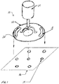
- FIG. 1
- shows a perspective view of a first illustrative embodiment of a pulse impingement variable timing apparatus according to the present invention, said embodiment working according to the method of the present invention;
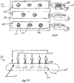
- FIG. 2
- shows a top view of the first illustrative embodiment apparatus of
FIG. 1 ; - FIG. 3
- shows a cross-sectional side view of the first illustrative embodiment apparatus of
FIG. 1 andFIG. 2 ; - FIG. 4
- shows a schematic view of a second illustrative embodiment (with sliding plates attached to solenoid coils) of a pulse impingement variable timing apparatus according to the present invention, said embodiment working according to the method of the present invention;
- FIG. 5A
- shows a schematic view of a third illustrative embodiment of a pulse impingement variable timing apparatus according to the present invention, said embodiment working according to the method of the present invention; and
- FIG. 5B
- shows a schematic view of a fourth illustrative embodiment (with pulsed impingement hood with actuated valves) of a pulse impingement variable timing apparatus according to the present invention, said embodiment working according to the method of the present invention.
- The accompanying drawings are included to provide a further understanding of the apparatus and method(s) provided herein and are incorporated in and constitute a part of this specification. The drawings illustrate various embodiments of the apparatus and method(s) provided herein and, together with the description, serve to explain the principles described herein but are not intended to limit the specification or any of the claims. In the accompanying drawings, like equipment is labelled with the same reference numerals throughout the description of
FIG. 1 to FIG. 5B . - Before explaining the present inventive embodiments in detail, it is to be understood that the embodiments are not limited in its respective application to the details of construction and arrangement of parts illustrated in the accompanying drawings, since the present invention is capable of other embodiments and of being practiced or carried out in various ways. Also, it is to be understood that the phraseology or terminology employed herein is for the purpose of description and not of limitation.
- In the following description, terms such a horizontal, upright, vertical, above, below, beneath and the like, are used solely for the purpose of clarity illustrating the present invention and should not be taken as words of limitation. The drawings are for the purpose of illustrating the present invention and are not intended to be to scale.
- The present apparatus and method embodiments shown in
FIG. 1 to FIG. 5B pulse an impingement gas flow through impingement holes at a frequency that maximizes heat transfer at the product surface by periodically impacting the product surface with gas flow, and then eliminating gas flow for a select or prearranged period of time to stop an increasing resistance to the flow. With the present embodiments, maximum heat transfer can be continuously maintained at the product surface. - In addition, by controlling pulses of gas flow so that adjacent holes will not flow gas (or gas columns) at the same time, the negating effect of flow from adjacent holes impacting each other is eliminated.
- This
present apparatus embodiments 10 ofFIG. 1 to FIG. 3 include a rotatingdisc 12 or plate that is placed overtop ofholes 14 in an existingimpingement plate 16;discharging slots 18 being cut into the rotatingdisc 12 that are slightly wider than the diameter of the existingholes 14 in theimpingement plate 16 and aligned with theimpingement holes 18 as thedisc 12 rotates, so thatgas 20 flows through theslot 18 area and then through theimpingement hole 14, but will prevent flow when thesolid material 22 of thedisc 12 covers and is in registration with theimpingement holes 14. - This embodiment has
slots 18 that vary the period of flow of thegas 20 versus non-flow of thegas 20, depending on the length of theslot 18 versus thesolid material 22 length of thedisc 12, and the speed of movement of therotating disc 12. - This embodiment has a
motor 24 to drive thedisc 12 at variable revolutions per minute to control pulse duration, thereby varying rotation from a maximum of 1800 rounds per minute (rpm) to a minimum of 30 rpm. - The
slots 18 of this embodiment are positioned so thatadjacent holes 14 do not permit flow of thegas 20 at the same time, thereby eliminating interference of flow betweenadjacent holes 14, and maximizing heat transfer to the product. - This embodiment allows
impingement holes 14 to be spaced for maximum heat transfer coverage of for example food product, while allowing flow through only half of theholes 14 at any one time, thereby increasing heat transfer due to higher hood pressure at only slightly increased power rate for the blowers. - In this embodiment according to
FIG. 1 to FIG. 3 , themovable plate 12 may comprise at least one elongated planar member, in particular a plurality of elongated planar members, slidable into and out of position with respect to theimpingement plate 16. - Solenoid valves may be provided for moving each elongated planar member in a first direction to cover at least a portion of the first plurality of
holes 14, and a biasing member, in particular a spring, may be provided for moving each elongated planar member in a second direction opposite to the first direction to align the first plurality ofholes 14 and the second plurality ofholes 18 into registration for providing the gas flow passageways. - Another
apparatus embodiment 110 shown atFIG. 4 includessliding plates 112 which coact with theimpingement plate 114 to open and close theimpingement holes 116 to allow pulsing of gas flow therethrough. The slidingplates 112 can be actuated by asolenoid valve 118 to close theholes 116, with aspring 120 that would bias theplate 112 back to its original position and alignholes 122 in theplates 112 to be in registration with the impingement holes 116 to open theholes 116 again to gas flow. -
Further apparatus embodiments FIG. 5A and atFIG. 5B , respectively: - In the
embodiment 210 according toFIG. 5A , anindividual piston 212 for each impingement hole 214 or port uses a high pressure gas pulse or burst to close the hole 214, with thepiston 212, and a spring 216 to bias thepiston 212 in a reverse direction to open the hole 214 again to allow gas flow through the hole 214. The burst delay 222 to thepistons 212 is approximately 90 psig (approximately 620.53 kPa). - This embodiment with the
piston 212 also acts to keep the impingement hole 214 free of ice, and an additional benefit of knocking ice free from theentire impingement plate 218 due to the impact of thepistons 212 on theimpingement plate 218. - In the
embodiment 210 according toFIG. 5A , allpistons 212 open and close at the same time, so all impingement ports 214 produce columns of high velocity gas flow at the same time. Animpingement hood 220 contains theimpingement plate 218 and thepistons 212. The impingement pressure is approximately four inches (approximately 10.16 cm) water column. - In the
embodiment 310 according toFIG. 5B , eachindividual piston 312 can be energized separately or individually, because eachpiston 312 has its own control valve 322 (provided withgas 324 with approximately 90 psig (approximately 620.53 kPa)). This allows to open and close adjacent impingement holes 314 separately with thepistons 312 at select, different time intervals in order to control the interaction of adjacent impingement holes 314. - An
impingement hood 320 contains theimpingement plate 318 and thepistons 312. Thesprings 316 are constructed and function similar to the springs 216. Theimpingement pressure 326 is approximately six inches (approximately 15.24 cm) water column to approximately ten inches (approximately 25.4 cm) water column. - In the embodiment of
FIG. 5A , opening and closing all holes at the same time will cause adjacent holes to produce jets at the same time. This produces columns of high velocity gas that will impact the food product at the same time, and then the gas will radiate outward. As the gas flow does so, the adjacent gas streams will impact each other and create a certain amount of turbulence at the product surface in between each column of gas. - In the embodiment of
FIG. 5B , a user can select when to open and close adjacent holes and columns of gas and therefore, the user can control the interaction of adjacent gas streams. This is beneficial to allow each gas column to spread radially somewhat before the gas impacts with another radiating column of gas. - The present embodiments provide combinations of open time and closed time for each impingement hole and adjacent impingement holes in order to create the optimal combination that produces the maximum heat transfer by eliminating resistance at the product surface.
- The foregoing apparatus embodiments 10, 110, 210, 310 of
FIG. 1 to FIG. 5B : - increase impingement heat transfer rates by creating and using pulsed impingement gas flows;
- reduce freezing times in view of the increased heat transfer rate achieved;
- create smaller ice crystals in the food product, thereby resulting in less product damage during the freezing process;
- reduce product dehydration due to the faster freezing process resulting in higher overall production yield of the product;
- provide a variable impingement duration, thereby resulting in an optimal pulse duration for each product and its particular surface; and
- reduce the number of holes that flow gas therethrough at any given time, resulting in reducing total flow requirement, but still using only slightly more power due to higher pressure requirement.
- It will be understood that the embodiments described herein are merely exemplary, and that one skilled in the art may make variations and modifications without departing from the spirit and scope of the present invention. All such variations and modifications are intended to be included within the scope of the present invention as described and claimed herein. Further, all embodiments disclosed are not necessarily in the alternative, as various embodiments of the present invention may be combined to provide the desired result.
-
- 10
- impingement apparatus (first embodiment; cf.
FIG. 1 to FIG. 3 ) - 12
- movable disc, in particular rotating disc, or movable plate, in particular rotating plate
- 14
- hole, in particular impingement hole, or port, in particular impingement port
- 16
- impingement plate or stationary plate
- 18
- discharging slot or gas pulse slot, in particular rotating gas pulse slot
- 20
- gas
- 22
- solid material of movable disc or
movable plate 12 - 24
- motor, in particular drive motor, for example variable speed drive motor
- 26
- drive motor, in particular blower drive motor, for example impingement blower drive motor
- 28
- blower wheel
- 30
- impingement hood
- 110
- impingement apparatus (second embodiment; cf.
FIG. 4 ) - 112
- sliding plate
- 114
- impingement plate
- 116
- hole, in particular impingement hole, or port, in particular impingement port
- 118
- valve, in particular movable valve, for example solenoid valve
- 120
- biasing member, in particular spring
- 122
- hole in sliding
plate 112 - 210
- impingement apparatus (third embodiment; cf.
FIG. 5A ) - 212
- piston, in particular movable piston
- 214
- hole, in particular impingement hole, or port, in particular impingement port
- 216
- biasing member, in particular spring
- 218
- impingement plate
- 220
- impingement hood
- 222
- burst delay to
piston 212 - 310
- impingement apparatus (fourth embodiment; cf.
FIG. 5B ) - 312
- piston, in particular movable piston
- 314
- hole, in particular impingement hole, or port, in particular impingement port
- 316
- biasing member, in particular spring
- 318
- impingement plate
- 320
- impingement hood
- 322
- control valve
- 324
- gas, in particular pressurized gas
- 326
- impingement pressure
Claims (15)
- An impingement apparatus (10) for a freezer, comprising:- an impingement plate (16) having a first plurality of holes (14) therethrough; and- at least one movable plate (12) having a second plurality of holes (18) therethrough, the at least one movable plate (12) positioned proximate to a surface of the impingement plate (16) and movable to align select ones of the second plurality of holes (18) in registration with select ones of the first plurality of holes (14) for providing a plurality of gas (20) flow passageways within the freezer.
- The apparatus according to claim 1, wherein each one of the first plurality of holes (14) have a first diameter, and each one of the second plurality of holes (18) have a second diameter greater than the first diameter.
- The apparatus according to claim 1 or 2, wherein each one of the first plurality of holes (14) comprise a circular shape, and each one of the second plurality of holes (18) comprise a slot-like shape.
- The apparatus according to claim 3, wherein the slot-like shape is longer than the circular shape.
- The apparatus according to at least one of claims 1 to 4, wherein the at least one movable plate (12) comprises a disc mounted for rotation in close proximity to the surface of the impingement plate (16).
- The apparatus according to at least one of claims 1 to 5, wherein the at least one movable plate (12) comprises at least one elongated planar member slidable into and out of position with respect to the impingement plate (16).
- The apparatus according to claim 6, wherein the at least one movable plate (12) comprises a plurality of elongated planar members slidable into and out of position with respect to the impingement plate (16).
- The apparatus according to claim 6 or 7, further comprising:- at least one valve for moving the at least one elongated planar member in a first direction to cover at least a portion of the first plurality of holes (14); and- at least one biasing member for moving the at least one elongated planar member in a second direction opposite to the first direction to align the first plurality of holes (14) and the second plurality of holes (18) into registration for providing the gas (20) flow passageways.
- The apparatus according to claim 8, wherein the at least one valve is at least one solenoid valve.
- An impingement apparatus (110) for a freezer, comprising:- an impingement plate (114) having a plurality of holes (116) therethrough;- a valve assembly comprising at least one movable valve (118) in registration with select ones of the plurality of holes (116) for being pressurized to close a corresponding one of the holes (116);- at least one biasing member (120) mounted for coaction with the at least one movable valve (118) to bias the at least one movable valve (118) out of the corresponding one of the holes (116) for providing gas passageways through the select ones of the plurality of holes (116); and- a pressurized gas for providing a gas pulse to the valve assembly to close the at least one movable valve (118) at the select one of the holes (116) and the gas passageways.
- An impingement apparatus (210; 310) for a freezer, comprising:- an impingement plate (218; 318) having a plurality of holes (214; 314) therethrough;- a piston assembly comprising at least one movable piston (212; 312) for select ones of the plurality of holes (214; 314), each of the movable pistons (212; 312) for being pressurized to close a corresponding one of the holes (214; 314);- at least one biasing member (216; 316) mounted for coaction with the at least one movable piston (212; 312) to bias the at least one movable piston (212; 312) out of the corresponding one of the plurality of holes (214; 314) for providing a gas passageway through each of the select ones of the plurality of holes (214; 314); and- a pressurized gas (324) for providing a gas pulse to the piston assembly to close the at least one movable piston (212; 312) and the gas passageways at the select ones of the impingement holes (214; 314).
- The apparatus according to claim 11, wherein pistons (212) of the piston assembly move- concurrently with other pistons (212) of the piston assembly, or- at different time intervals from other pistons (312) of the piston assembly.
- The apparatus according to claim 11 or 12, wherein each piston (312) comprises an individual control valve (322) for being energized separately or individually
- The apparatus according to at least one of claims 8 to 13, wherein the at least one biasing member (120; 216; 316) is at least one spring.
- The apparatus according to at least one of claims 1 to 14, provided for chilling and/or freezing at least one product, in particular at least one food product.
Applications Claiming Priority (1)
| Application Number | Priority Date | Filing Date | Title |
|---|---|---|---|
| US201662439551P | 2016-12-28 | 2016-12-28 |
Publications (2)
| Publication Number | Publication Date |
|---|---|
| EP3343137A1 true EP3343137A1 (en) | 2018-07-04 |
| EP3343137B1 EP3343137B1 (en) | 2019-07-24 |
Family
ID=59070464
Family Applications (1)
| Application Number | Title | Priority Date | Filing Date |
|---|---|---|---|
| EP17175602.6A Active EP3343137B1 (en) | 2016-12-28 | 2017-06-12 | Impingement apparatus for freezer |
Country Status (1)
| Country | Link |
|---|---|
| EP (1) | EP3343137B1 (en) |
Citations (5)
| Publication number | Priority date | Publication date | Assignee | Title |
|---|---|---|---|---|
| JPH046379A (en) * | 1990-04-24 | 1992-01-10 | Mitsubishi Electric Corp | Refrigerator |
| US5941087A (en) * | 1997-07-31 | 1999-08-24 | Daewoo Electronics Co., Ltd. | Refrigerator having an apparatus for preventing an air from flowing into the refrigerator |
| JP2005173852A (en) * | 2003-12-10 | 2005-06-30 | Fuji Electric Retail Systems Co Ltd | Vending machine |
| US20050241333A1 (en) * | 2003-12-03 | 2005-11-03 | Hamilton Robert W | Rate-controlled freezer and cooling methods thereof |
| EP2733447A1 (en) * | 2012-11-15 | 2014-05-21 | Linde Aktiengesellschaft | Oscillating flow freezer |
-
2017
- 2017-06-12 EP EP17175602.6A patent/EP3343137B1/en active Active
Patent Citations (5)
| Publication number | Priority date | Publication date | Assignee | Title |
|---|---|---|---|---|
| JPH046379A (en) * | 1990-04-24 | 1992-01-10 | Mitsubishi Electric Corp | Refrigerator |
| US5941087A (en) * | 1997-07-31 | 1999-08-24 | Daewoo Electronics Co., Ltd. | Refrigerator having an apparatus for preventing an air from flowing into the refrigerator |
| US20050241333A1 (en) * | 2003-12-03 | 2005-11-03 | Hamilton Robert W | Rate-controlled freezer and cooling methods thereof |
| JP2005173852A (en) * | 2003-12-10 | 2005-06-30 | Fuji Electric Retail Systems Co Ltd | Vending machine |
| EP2733447A1 (en) * | 2012-11-15 | 2014-05-21 | Linde Aktiengesellschaft | Oscillating flow freezer |
Also Published As
| Publication number | Publication date |
|---|---|
| EP3343137B1 (en) | 2019-07-24 |
Similar Documents
| Publication | Publication Date | Title |
|---|---|---|
| KR101658045B1 (en) | Fruit pulp and seed separation device | |
| EP3482031B1 (en) | Flow-through pulsing assembly for use in downhole operations | |
| EP2733447B1 (en) | Oscillating flow freezer | |
| RU2012152706A (en) | CONTROL OF THE PULSING FLOW OF THE SPRAYER INJECTOR USING ROTARY STEP-BY-STEP POSITIONS | |
| EP3343137B1 (en) | Impingement apparatus for freezer | |
| CN104896828B (en) | refrigerator | |
| KR101383219B1 (en) | Percussion equipment driven by a pressurized incompressible fluid | |
| CN114414616A (en) | Closed experimental device for observing melting, freezing and impacting behaviors of ice crystals | |
| JP2018122225A5 (en) | apparatus | |
| CN110440509B (en) | Refrigerating chamber shell | |
| CN108472702A (en) | Cooling device and cooling method | |
| CN112005849A (en) | Intelligent water-saving irrigation spraying system and working method | |
| JP4229864B2 (en) | Cooker | |
| RU2607754C1 (en) | Device for automatic pucks feed for training hockey | |
| US2749721A (en) | Ice machine | |
| MX391024B (en) | INTEGRATED MOTOR DRIVE SYSTEM FOR CREAMY PRODUCT DISPENSER. | |
| RU2453779C1 (en) | Device for poultry chilling by carbon dioxide | |
| EP2892668B1 (en) | Rotary valve system | |
| RU2015150163A (en) | PRE-COOLING SYSTEM WITH CONTROLLED INTERNAL REGULATION | |
| KR102367571B1 (en) | Sprockets with improved torque and cooling towers with them | |
| CN205735940U (en) | PVC profile chiller | |
| EP3201543B1 (en) | A refrigerator comprising a humidity and temperature controlled special compartment | |
| EP3343140B1 (en) | Apparatus for chilling and/or freezing products | |
| CN109073310A (en) | Apparatus for producing pulsating impingement jets in freezers | |
| WO2016037719A1 (en) | A refrigerator comprising a humidity and temperature controlled compartment |
Legal Events
| Date | Code | Title | Description |
|---|---|---|---|
| PUAI | Public reference made under article 153(3) epc to a published international application that has entered the european phase |
Free format text: ORIGINAL CODE: 0009012 |
|
| STAA | Information on the status of an ep patent application or granted ep patent |
Free format text: STATUS: THE APPLICATION HAS BEEN PUBLISHED |
|
| AK | Designated contracting states |
Kind code of ref document: A1 Designated state(s): AL AT BE BG CH CY CZ DE DK EE ES FI FR GB GR HR HU IE IS IT LI LT LU LV MC MK MT NL NO PL PT RO RS SE SI SK SM TR |
|
| AX | Request for extension of the european patent |
Extension state: BA ME |
|
| STAA | Information on the status of an ep patent application or granted ep patent |
Free format text: STATUS: REQUEST FOR EXAMINATION WAS MADE |
|
| GRAP | Despatch of communication of intention to grant a patent |
Free format text: ORIGINAL CODE: EPIDOSNIGR1 |
|
| STAA | Information on the status of an ep patent application or granted ep patent |
Free format text: STATUS: GRANT OF PATENT IS INTENDED |
|
| 17P | Request for examination filed |
Effective date: 20190104 |
|
| RBV | Designated contracting states (corrected) |
Designated state(s): AL AT BE BG CH CY CZ DE DK EE ES FI FR GB GR HR HU IE IS IT LI LT LU LV MC MK MT NL NO PL PT RO RS SE SI SK SM TR |
|
| INTG | Intention to grant announced |
Effective date: 20190214 |
|
| GRAS | Grant fee paid |
Free format text: ORIGINAL CODE: EPIDOSNIGR3 |
|
| GRAA | (expected) grant |
Free format text: ORIGINAL CODE: 0009210 |
|
| STAA | Information on the status of an ep patent application or granted ep patent |
Free format text: STATUS: THE PATENT HAS BEEN GRANTED |
|
| AK | Designated contracting states |
Kind code of ref document: B1 Designated state(s): AL AT BE BG CH CY CZ DE DK EE ES FI FR GB GR HR HU IE IS IT LI LT LU LV MC MK MT NL NO PL PT RO RS SE SI SK SM TR |
|
| REG | Reference to a national code |
Ref country code: GB Ref legal event code: FG4D |
|
| REG | Reference to a national code |
Ref country code: CH Ref legal event code: EP |
|
| REG | Reference to a national code |
Ref country code: DE Ref legal event code: R096 Ref document number: 602017005448 Country of ref document: DE |
|
| REG | Reference to a national code |
Ref country code: AT Ref legal event code: REF Ref document number: 1158676 Country of ref document: AT Kind code of ref document: T Effective date: 20190815 |
|
| REG | Reference to a national code |
Ref country code: IE Ref legal event code: FG4D |
|
| REG | Reference to a national code |
Ref country code: NL Ref legal event code: MP Effective date: 20190724 |
|
| REG | Reference to a national code |
Ref country code: LT Ref legal event code: MG4D |
|
| REG | Reference to a national code |
Ref country code: AT Ref legal event code: MK05 Ref document number: 1158676 Country of ref document: AT Kind code of ref document: T Effective date: 20190724 |
|
| PG25 | Lapsed in a contracting state [announced via postgrant information from national office to epo] |
Ref country code: HR Free format text: LAPSE BECAUSE OF FAILURE TO SUBMIT A TRANSLATION OF THE DESCRIPTION OR TO PAY THE FEE WITHIN THE PRESCRIBED TIME-LIMIT Effective date: 20190724 Ref country code: LT Free format text: LAPSE BECAUSE OF FAILURE TO SUBMIT A TRANSLATION OF THE DESCRIPTION OR TO PAY THE FEE WITHIN THE PRESCRIBED TIME-LIMIT Effective date: 20190724 Ref country code: NL Free format text: LAPSE BECAUSE OF FAILURE TO SUBMIT A TRANSLATION OF THE DESCRIPTION OR TO PAY THE FEE WITHIN THE PRESCRIBED TIME-LIMIT Effective date: 20190724 Ref country code: PT Free format text: LAPSE BECAUSE OF FAILURE TO SUBMIT A TRANSLATION OF THE DESCRIPTION OR TO PAY THE FEE WITHIN THE PRESCRIBED TIME-LIMIT Effective date: 20191125 Ref country code: SE Free format text: LAPSE BECAUSE OF FAILURE TO SUBMIT A TRANSLATION OF THE DESCRIPTION OR TO PAY THE FEE WITHIN THE PRESCRIBED TIME-LIMIT Effective date: 20190724 Ref country code: BG Free format text: LAPSE BECAUSE OF FAILURE TO SUBMIT A TRANSLATION OF THE DESCRIPTION OR TO PAY THE FEE WITHIN THE PRESCRIBED TIME-LIMIT Effective date: 20191024 Ref country code: FI Free format text: LAPSE BECAUSE OF FAILURE TO SUBMIT A TRANSLATION OF THE DESCRIPTION OR TO PAY THE FEE WITHIN THE PRESCRIBED TIME-LIMIT Effective date: 20190724 Ref country code: AT Free format text: LAPSE BECAUSE OF FAILURE TO SUBMIT A TRANSLATION OF THE DESCRIPTION OR TO PAY THE FEE WITHIN THE PRESCRIBED TIME-LIMIT Effective date: 20190724 Ref country code: NO Free format text: LAPSE BECAUSE OF FAILURE TO SUBMIT A TRANSLATION OF THE DESCRIPTION OR TO PAY THE FEE WITHIN THE PRESCRIBED TIME-LIMIT Effective date: 20191024 |
|
| PG25 | Lapsed in a contracting state [announced via postgrant information from national office to epo] |
Ref country code: RS Free format text: LAPSE BECAUSE OF FAILURE TO SUBMIT A TRANSLATION OF THE DESCRIPTION OR TO PAY THE FEE WITHIN THE PRESCRIBED TIME-LIMIT Effective date: 20190724 Ref country code: IS Free format text: LAPSE BECAUSE OF FAILURE TO SUBMIT A TRANSLATION OF THE DESCRIPTION OR TO PAY THE FEE WITHIN THE PRESCRIBED TIME-LIMIT Effective date: 20191124 Ref country code: GR Free format text: LAPSE BECAUSE OF FAILURE TO SUBMIT A TRANSLATION OF THE DESCRIPTION OR TO PAY THE FEE WITHIN THE PRESCRIBED TIME-LIMIT Effective date: 20191025 Ref country code: LV Free format text: LAPSE BECAUSE OF FAILURE TO SUBMIT A TRANSLATION OF THE DESCRIPTION OR TO PAY THE FEE WITHIN THE PRESCRIBED TIME-LIMIT Effective date: 20190724 Ref country code: AL Free format text: LAPSE BECAUSE OF FAILURE TO SUBMIT A TRANSLATION OF THE DESCRIPTION OR TO PAY THE FEE WITHIN THE PRESCRIBED TIME-LIMIT Effective date: 20190724 Ref country code: ES Free format text: LAPSE BECAUSE OF FAILURE TO SUBMIT A TRANSLATION OF THE DESCRIPTION OR TO PAY THE FEE WITHIN THE PRESCRIBED TIME-LIMIT Effective date: 20190724 |
|
| PG25 | Lapsed in a contracting state [announced via postgrant information from national office to epo] |
Ref country code: TR Free format text: LAPSE BECAUSE OF FAILURE TO SUBMIT A TRANSLATION OF THE DESCRIPTION OR TO PAY THE FEE WITHIN THE PRESCRIBED TIME-LIMIT Effective date: 20190724 |
|
| PG25 | Lapsed in a contracting state [announced via postgrant information from national office to epo] |
Ref country code: PL Free format text: LAPSE BECAUSE OF FAILURE TO SUBMIT A TRANSLATION OF THE DESCRIPTION OR TO PAY THE FEE WITHIN THE PRESCRIBED TIME-LIMIT Effective date: 20190724 Ref country code: DK Free format text: LAPSE BECAUSE OF FAILURE TO SUBMIT A TRANSLATION OF THE DESCRIPTION OR TO PAY THE FEE WITHIN THE PRESCRIBED TIME-LIMIT Effective date: 20190724 Ref country code: IT Free format text: LAPSE BECAUSE OF FAILURE TO SUBMIT A TRANSLATION OF THE DESCRIPTION OR TO PAY THE FEE WITHIN THE PRESCRIBED TIME-LIMIT Effective date: 20190724 Ref country code: RO Free format text: LAPSE BECAUSE OF FAILURE TO SUBMIT A TRANSLATION OF THE DESCRIPTION OR TO PAY THE FEE WITHIN THE PRESCRIBED TIME-LIMIT Effective date: 20190724 Ref country code: EE Free format text: LAPSE BECAUSE OF FAILURE TO SUBMIT A TRANSLATION OF THE DESCRIPTION OR TO PAY THE FEE WITHIN THE PRESCRIBED TIME-LIMIT Effective date: 20190724 |
|
| PG25 | Lapsed in a contracting state [announced via postgrant information from national office to epo] |
Ref country code: SM Free format text: LAPSE BECAUSE OF FAILURE TO SUBMIT A TRANSLATION OF THE DESCRIPTION OR TO PAY THE FEE WITHIN THE PRESCRIBED TIME-LIMIT Effective date: 20190724 Ref country code: CZ Free format text: LAPSE BECAUSE OF FAILURE TO SUBMIT A TRANSLATION OF THE DESCRIPTION OR TO PAY THE FEE WITHIN THE PRESCRIBED TIME-LIMIT Effective date: 20190724 Ref country code: SK Free format text: LAPSE BECAUSE OF FAILURE TO SUBMIT A TRANSLATION OF THE DESCRIPTION OR TO PAY THE FEE WITHIN THE PRESCRIBED TIME-LIMIT Effective date: 20190724 Ref country code: IS Free format text: LAPSE BECAUSE OF FAILURE TO SUBMIT A TRANSLATION OF THE DESCRIPTION OR TO PAY THE FEE WITHIN THE PRESCRIBED TIME-LIMIT Effective date: 20200224 |
|
| REG | Reference to a national code |
Ref country code: DE Ref legal event code: R097 Ref document number: 602017005448 Country of ref document: DE |
|
| RAP2 | Party data changed (patent owner data changed or rights of a patent transferred) |
Owner name: LINDE GMBH |
|
| PLBE | No opposition filed within time limit |
Free format text: ORIGINAL CODE: 0009261 |
|
| STAA | Information on the status of an ep patent application or granted ep patent |
Free format text: STATUS: NO OPPOSITION FILED WITHIN TIME LIMIT |
|
| REG | Reference to a national code |
Ref country code: DE Ref legal event code: R081 Ref document number: 602017005448 Country of ref document: DE Owner name: LINDE GMBH, DE Free format text: FORMER OWNER: LINDE AKTIENGESELLSCHAFT, 80331 MUENCHEN, DE |
|
| PG2D | Information on lapse in contracting state deleted |
Ref country code: IS |
|
| 26N | No opposition filed |
Effective date: 20200603 |
|
| PG25 | Lapsed in a contracting state [announced via postgrant information from national office to epo] |
Ref country code: SI Free format text: LAPSE BECAUSE OF FAILURE TO SUBMIT A TRANSLATION OF THE DESCRIPTION OR TO PAY THE FEE WITHIN THE PRESCRIBED TIME-LIMIT Effective date: 20190724 |
|
| PG25 | Lapsed in a contracting state [announced via postgrant information from national office to epo] |
Ref country code: MC Free format text: LAPSE BECAUSE OF FAILURE TO SUBMIT A TRANSLATION OF THE DESCRIPTION OR TO PAY THE FEE WITHIN THE PRESCRIBED TIME-LIMIT Effective date: 20190724 |
|
| REG | Reference to a national code |
Ref country code: CH Ref legal event code: PL |
|
| PG25 | Lapsed in a contracting state [announced via postgrant information from national office to epo] |
Ref country code: LU Free format text: LAPSE BECAUSE OF NON-PAYMENT OF DUE FEES Effective date: 20200612 |
|
| REG | Reference to a national code |
Ref country code: BE Ref legal event code: MM Effective date: 20200630 |
|
| PG25 | Lapsed in a contracting state [announced via postgrant information from national office to epo] |
Ref country code: IE Free format text: LAPSE BECAUSE OF NON-PAYMENT OF DUE FEES Effective date: 20200612 Ref country code: CH Free format text: LAPSE BECAUSE OF NON-PAYMENT OF DUE FEES Effective date: 20200630 Ref country code: LI Free format text: LAPSE BECAUSE OF NON-PAYMENT OF DUE FEES Effective date: 20200630 |
|
| PG25 | Lapsed in a contracting state [announced via postgrant information from national office to epo] |
Ref country code: BE Free format text: LAPSE BECAUSE OF NON-PAYMENT OF DUE FEES Effective date: 20200630 |
|
| PG25 | Lapsed in a contracting state [announced via postgrant information from national office to epo] |
Ref country code: MT Free format text: LAPSE BECAUSE OF FAILURE TO SUBMIT A TRANSLATION OF THE DESCRIPTION OR TO PAY THE FEE WITHIN THE PRESCRIBED TIME-LIMIT Effective date: 20190724 Ref country code: CY Free format text: LAPSE BECAUSE OF FAILURE TO SUBMIT A TRANSLATION OF THE DESCRIPTION OR TO PAY THE FEE WITHIN THE PRESCRIBED TIME-LIMIT Effective date: 20190724 |
|
| PG25 | Lapsed in a contracting state [announced via postgrant information from national office to epo] |
Ref country code: MK Free format text: LAPSE BECAUSE OF FAILURE TO SUBMIT A TRANSLATION OF THE DESCRIPTION OR TO PAY THE FEE WITHIN THE PRESCRIBED TIME-LIMIT Effective date: 20190724 |
|
| PGFP | Annual fee paid to national office [announced via postgrant information from national office to epo] |
Ref country code: DE Payment date: 20250618 Year of fee payment: 9 |
|
| PGFP | Annual fee paid to national office [announced via postgrant information from national office to epo] |
Ref country code: GB Payment date: 20250620 Year of fee payment: 9 |
|
| PGFP | Annual fee paid to national office [announced via postgrant information from national office to epo] |
Ref country code: FR Payment date: 20250626 Year of fee payment: 9 |