EP3343052A1 - Magnetic bearing device and hot-dip galvanizing apparatus comprising same - Google Patents
Magnetic bearing device and hot-dip galvanizing apparatus comprising same Download PDFInfo
- Publication number
- EP3343052A1 EP3343052A1 EP15902340.7A EP15902340A EP3343052A1 EP 3343052 A1 EP3343052 A1 EP 3343052A1 EP 15902340 A EP15902340 A EP 15902340A EP 3343052 A1 EP3343052 A1 EP 3343052A1
- Authority
- EP
- European Patent Office
- Prior art keywords
- magnetic
- roll shaft
- bearing device
- support
- radial
- Prior art date
- Legal status (The legal status is an assumption and is not a legal conclusion. Google has not performed a legal analysis and makes no representation as to the accuracy of the status listed.)
- Withdrawn
Links
Images



Classifications
-
- C—CHEMISTRY; METALLURGY
- C23—COATING METALLIC MATERIAL; COATING MATERIAL WITH METALLIC MATERIAL; CHEMICAL SURFACE TREATMENT; DIFFUSION TREATMENT OF METALLIC MATERIAL; COATING BY VACUUM EVAPORATION, BY SPUTTERING, BY ION IMPLANTATION OR BY CHEMICAL VAPOUR DEPOSITION, IN GENERAL; INHIBITING CORROSION OF METALLIC MATERIAL OR INCRUSTATION IN GENERAL
- C23C—COATING METALLIC MATERIAL; COATING MATERIAL WITH METALLIC MATERIAL; SURFACE TREATMENT OF METALLIC MATERIAL BY DIFFUSION INTO THE SURFACE, BY CHEMICAL CONVERSION OR SUBSTITUTION; COATING BY VACUUM EVAPORATION, BY SPUTTERING, BY ION IMPLANTATION OR BY CHEMICAL VAPOUR DEPOSITION, IN GENERAL
- C23C2/00—Hot-dipping or immersion processes for applying the coating material in the molten state without affecting the shape; Apparatus therefor
- C23C2/003—Apparatus
- C23C2/0034—Details related to elements immersed in bath
- C23C2/00342—Moving elements, e.g. pumps or mixers
- C23C2/00344—Means for moving substrates, e.g. immersed rollers or immersed bearings
-
- C—CHEMISTRY; METALLURGY
- C23—COATING METALLIC MATERIAL; COATING MATERIAL WITH METALLIC MATERIAL; CHEMICAL SURFACE TREATMENT; DIFFUSION TREATMENT OF METALLIC MATERIAL; COATING BY VACUUM EVAPORATION, BY SPUTTERING, BY ION IMPLANTATION OR BY CHEMICAL VAPOUR DEPOSITION, IN GENERAL; INHIBITING CORROSION OF METALLIC MATERIAL OR INCRUSTATION IN GENERAL
- C23C—COATING METALLIC MATERIAL; COATING MATERIAL WITH METALLIC MATERIAL; SURFACE TREATMENT OF METALLIC MATERIAL BY DIFFUSION INTO THE SURFACE, BY CHEMICAL CONVERSION OR SUBSTITUTION; COATING BY VACUUM EVAPORATION, BY SPUTTERING, BY ION IMPLANTATION OR BY CHEMICAL VAPOUR DEPOSITION, IN GENERAL
- C23C2/00—Hot-dipping or immersion processes for applying the coating material in the molten state without affecting the shape; Apparatus therefor
- C23C2/04—Hot-dipping or immersion processes for applying the coating material in the molten state without affecting the shape; Apparatus therefor characterised by the coating material
- C23C2/06—Zinc or cadmium or alloys based thereon
-
- C—CHEMISTRY; METALLURGY
- C23—COATING METALLIC MATERIAL; COATING MATERIAL WITH METALLIC MATERIAL; CHEMICAL SURFACE TREATMENT; DIFFUSION TREATMENT OF METALLIC MATERIAL; COATING BY VACUUM EVAPORATION, BY SPUTTERING, BY ION IMPLANTATION OR BY CHEMICAL VAPOUR DEPOSITION, IN GENERAL; INHIBITING CORROSION OF METALLIC MATERIAL OR INCRUSTATION IN GENERAL
- C23C—COATING METALLIC MATERIAL; COATING MATERIAL WITH METALLIC MATERIAL; SURFACE TREATMENT OF METALLIC MATERIAL BY DIFFUSION INTO THE SURFACE, BY CHEMICAL CONVERSION OR SUBSTITUTION; COATING BY VACUUM EVAPORATION, BY SPUTTERING, BY ION IMPLANTATION OR BY CHEMICAL VAPOUR DEPOSITION, IN GENERAL
- C23C2/00—Hot-dipping or immersion processes for applying the coating material in the molten state without affecting the shape; Apparatus therefor
- C23C2/14—Removing excess of molten coatings; Controlling or regulating the coating thickness
-
- C—CHEMISTRY; METALLURGY
- C23—COATING METALLIC MATERIAL; COATING MATERIAL WITH METALLIC MATERIAL; CHEMICAL SURFACE TREATMENT; DIFFUSION TREATMENT OF METALLIC MATERIAL; COATING BY VACUUM EVAPORATION, BY SPUTTERING, BY ION IMPLANTATION OR BY CHEMICAL VAPOUR DEPOSITION, IN GENERAL; INHIBITING CORROSION OF METALLIC MATERIAL OR INCRUSTATION IN GENERAL
- C23C—COATING METALLIC MATERIAL; COATING MATERIAL WITH METALLIC MATERIAL; SURFACE TREATMENT OF METALLIC MATERIAL BY DIFFUSION INTO THE SURFACE, BY CHEMICAL CONVERSION OR SUBSTITUTION; COATING BY VACUUM EVAPORATION, BY SPUTTERING, BY ION IMPLANTATION OR BY CHEMICAL VAPOUR DEPOSITION, IN GENERAL
- C23C2/00—Hot-dipping or immersion processes for applying the coating material in the molten state without affecting the shape; Apparatus therefor
- C23C2/34—Hot-dipping or immersion processes for applying the coating material in the molten state without affecting the shape; Apparatus therefor characterised by the shape of the material to be treated
- C23C2/36—Elongated material
- C23C2/40—Plates; Strips
-
- F—MECHANICAL ENGINEERING; LIGHTING; HEATING; WEAPONS; BLASTING
- F16—ENGINEERING ELEMENTS AND UNITS; GENERAL MEASURES FOR PRODUCING AND MAINTAINING EFFECTIVE FUNCTIONING OF MACHINES OR INSTALLATIONS; THERMAL INSULATION IN GENERAL
- F16C—SHAFTS; FLEXIBLE SHAFTS; ELEMENTS OR CRANKSHAFT MECHANISMS; ROTARY BODIES OTHER THAN GEARING ELEMENTS; BEARINGS
- F16C13/00—Rolls, drums, discs, or the like; Bearings or mountings therefor
- F16C13/02—Bearings
-
- F—MECHANICAL ENGINEERING; LIGHTING; HEATING; WEAPONS; BLASTING
- F16—ENGINEERING ELEMENTS AND UNITS; GENERAL MEASURES FOR PRODUCING AND MAINTAINING EFFECTIVE FUNCTIONING OF MACHINES OR INSTALLATIONS; THERMAL INSULATION IN GENERAL
- F16C—SHAFTS; FLEXIBLE SHAFTS; ELEMENTS OR CRANKSHAFT MECHANISMS; ROTARY BODIES OTHER THAN GEARING ELEMENTS; BEARINGS
- F16C32/00—Bearings not otherwise provided for
- F16C32/04—Bearings not otherwise provided for using magnetic or electric supporting means
-
- F—MECHANICAL ENGINEERING; LIGHTING; HEATING; WEAPONS; BLASTING
- F16—ENGINEERING ELEMENTS AND UNITS; GENERAL MEASURES FOR PRODUCING AND MAINTAINING EFFECTIVE FUNCTIONING OF MACHINES OR INSTALLATIONS; THERMAL INSULATION IN GENERAL
- F16C—SHAFTS; FLEXIBLE SHAFTS; ELEMENTS OR CRANKSHAFT MECHANISMS; ROTARY BODIES OTHER THAN GEARING ELEMENTS; BEARINGS
- F16C32/00—Bearings not otherwise provided for
- F16C32/04—Bearings not otherwise provided for using magnetic or electric supporting means
- F16C32/0406—Magnetic bearings
- F16C32/0408—Passive magnetic bearings
-
- F—MECHANICAL ENGINEERING; LIGHTING; HEATING; WEAPONS; BLASTING
- F16—ENGINEERING ELEMENTS AND UNITS; GENERAL MEASURES FOR PRODUCING AND MAINTAINING EFFECTIVE FUNCTIONING OF MACHINES OR INSTALLATIONS; THERMAL INSULATION IN GENERAL
- F16C—SHAFTS; FLEXIBLE SHAFTS; ELEMENTS OR CRANKSHAFT MECHANISMS; ROTARY BODIES OTHER THAN GEARING ELEMENTS; BEARINGS
- F16C32/00—Bearings not otherwise provided for
- F16C32/04—Bearings not otherwise provided for using magnetic or electric supporting means
- F16C32/0406—Magnetic bearings
- F16C32/044—Active magnetic bearings
- F16C32/0474—Active magnetic bearings for rotary movement
-
- G—PHYSICS
- G01—MEASURING; TESTING
- G01H—MEASUREMENT OF MECHANICAL VIBRATIONS OR ULTRASONIC, SONIC OR INFRASONIC WAVES
- G01H17/00—Measuring mechanical vibrations or ultrasonic, sonic or infrasonic waves, not provided for in the other groups of this subclass
-
- F—MECHANICAL ENGINEERING; LIGHTING; HEATING; WEAPONS; BLASTING
- F16—ENGINEERING ELEMENTS AND UNITS; GENERAL MEASURES FOR PRODUCING AND MAINTAINING EFFECTIVE FUNCTIONING OF MACHINES OR INSTALLATIONS; THERMAL INSULATION IN GENERAL
- F16C—SHAFTS; FLEXIBLE SHAFTS; ELEMENTS OR CRANKSHAFT MECHANISMS; ROTARY BODIES OTHER THAN GEARING ELEMENTS; BEARINGS
- F16C2233/00—Monitoring condition, e.g. temperature, load, vibration
Definitions
- the present inventive concept relates to a magnetic bearing device and a hot-dip galvanizing apparatus including the magnetic bearing device.
- a steel sheet may be immersed in a galvanizing bath, filled with molten zinc via a snout, and may proceed in a vertical direction in a state of contact with a pot roll in the galvanizing bath, thereby being supported by the pot roll.
- the pot roll may be a sink roll or a stabilizing roll.
- a sink roll may function to change a moving direction of the steel sheet, and such a stabilizing roll may function to correct a shape of the steel sheet.
- the bearing When such a bearing is used in the galvanizing process, the bearing may be gradually abraded while the pot roll rotates in the hot-dip galvanizing bath, and vibrations and noise may occur due to unstable rotation.
- contact-type bearings not only drastically shorten the lifespan thereof, but may also cause surface defects on a plated steel sheet, such as non-uniformity in plating thickness deviations, due to vibrations of the pot roll.
- non-contact type bearing devices such as magnetic bearing devices have been developed, in order to prevent problems of the contact type bearing devices as described above.
- the lifespan of the magnetic bearing device may be shortened due to collisions with the roll axis.
- the pot roll may be vibrated when collisions between the magnetic bearing device and the roll axis occur, since the magnetic bearing device may not be precisely controlled.
- surface defects such as non-uniformity in plating thickness deviations, may occur in a plated steel sheet due to vibrations of the pot roll, similarly to those occurring in contact type bearing devices as described above.
- An aspect of the present inventive concept may provide a magnetic bearing device in which a support of a roll shaft is precisely controlled in a non-contact manner, and a hot-dip galvanizing apparatus including the magnetic bearing device.
- a magnetic bearing device may include a support unit disposed adjacent to a roll shaft and generating a magnetic field toward the roll shaft, and a magnetic force receiving unit coupled to the roll shaft and only including a magnetic material in a portion facing the support unit, wherein the magnetic material is magnetized by the magnetic force.
- the magnetic force receiving unit of the magnetic bearing device may include a magnetic member formed of the magnetic material and disposed on the portion facing the support unit in the roll shaft, and a nonmagnetic member formed of a nonmagnetic material and disposed on a portion other than the portion on which the magnetic member is disposed on the roll shaft.
- the magnetic force receiving unit of the magnetic bearing device may further include an axial sheath member fitted onto the roll shaft and with which the magnetic member and the nonmagnetic member are combined.
- the magnetic member of the magnetic bearing device may have a cylindrical shape, and have the same width as the portion facing the support unit in the roll shaft.
- the magnetic member of the magnetic bearing device may have a disc shape, and the number of the magnetic member may correspond to a width of the portion facing the support unit in the roll shaft.
- the roll shaft of the magnetic bearing device may be formed of a nonmagnetic material.
- the support unit of the magnetic bearing device may include a magnetic support disposed adjacent to the roll shaft and supporting the roll shaft in at least one of an axial direction or a radial direction of the roll shaft, and a sensor electrically connected to the magnetic support to measure and control an intensity of vibrations of the magnetic support.
- the magnetic support of the magnetic bearing device may further include a radial magnetic member disposed in a radial direction of the roll shaft and supporting the roll shaft in the radial direction of the roll shaft when the roll shaft rotates, and an axial magnetic member disposed to face a stepped portion, formed in the roll shaft or the axial sheath member of the magnetic force receiving unit fitted on the roll shaft, in an axial direction of the roll shaft and supporting the roll shaft in the axial direction of the roll shaft when the roll shaft rotates.
- the support unit of the magnetic bearing device may further include a housing part with which the magnetic support and the sensor are combined, and a radial touch disc having a disc shape and combined with the housing part or an inner side of the radial magnetic member, wherein an internal diameter of the radial touch disc is smaller than an internal diameter of the radial magnetic member.
- the support unit of the magnetic bearing device may further include an axial touch disc combined with the housing part to be disposed between the axial magnetic member and the stepped portion of the roll shaft.
- the magnetic force receiving unit of the magnetic bearing device may include the magnetic material only on a portion facing the magnetic support and the sensor in the roll shaft.
- a hot-dip galvanizing apparatus may include a galvanizing bath configured to accommodate molten zinc, a pot roll disposed on a transportation path of a steel sheet moving into the galvanizing bath, and the magnetic bearing device described above and disposed on a roll shaft of the pot roll.
- a magnetic bearing device and a hot-dip galvanizing apparatus including the magnetic bearing device according to an exemplary embodiment in the present disclosure can support a roll shaft in a non-contact manner.
- the magnetic force when the roll shaft is supported by magnetic force, the magnetic force can be controlled to only affect a portion to be supported in the roll shaft. Accordingly, the support of the roll shaft by the magnetic force can be precisely controlled in the magnetic bearing device and the hot-dip galvanizing apparatus including the magnetic bearing device according to the exemplary embodiment in the present disclosure.
- a magnetic bearing device 1 and a hot-dip galvanizing apparatus including the magnetic bearing device 1 may support a roll shaft 2, and more specifically, may support the roll shaft 2 in a non-contact manner.
- the magnetic bearing device 1 and the hot-dip galvanizing apparatus including the magnetic bearing device 1 may support the roll shaft 2 with magnetic force.
- the magnetic force may affect only a portion to be supported in the roll shaft 2, and thereby the support of the roll shaft 2 may be precisely controlled by the magnetic force.
- FIG. 1 is a perspective view illustrating a hot-dip galvanizing apparatus according to an exemplary embodiment in the present disclosure.
- the hot-dip galvanizing apparatus may include a galvanizing bath 4 in which molten zinc is accommodated, a pot roll 3 disposed on a transportation path of the steel sheet moving into the galvanizing bath 4, and a magnetic bearing device 1, to be described later, disposed on the roll shaft 2 of the pot roll 3.
- the galvanizing bath 4 and the pot roll 3 may be provided to galvanize the steel sheet.
- the pot roll 3 may include a sink roll configured to change a moving direction of the steel sheet, and a stabilizing roll configured to correct a shape of the steel sheet.
- the hot-dip galvanizing apparatus since the hot-dip galvanizing apparatus according to the exemplary embodiment in the present disclosure includes the magnetic bearing device 1, the roll shaft 2 of the pot roll 3 may be precisely supported.
- FIG. 2 is a cross-sectional view illustrating a magnetic bearing device 1 according to an exemplary embodiment in the present disclosure
- FIG. 3 is a side view illustrating a magnetic force receiving unit 200 of the magnetic bearing device 1 according to an exemplary embodiment in the present disclosure.
- the magnetic bearing device 1 may include a support unit 100 disposed adjacent to the roll shaft 2 and generating a magnetic field toward the roll shaft 2, and a magnetic force receiving unit 200 coupled to the roll shaft 2.
- the magnetic force receiving unit 200 may include a magnetic material in only a portion facing the support unit 100, thereby being magnetized with magnetic force of the magnetic field generated in the support unit 100.
- the support of the roll shaft 2 may be precisely controlled.
- the support unit 100 may function to support the roll shaft 2 in a non-contact manner using the magnetic force. That is, the support unit 100 may generate the magnetic field, and support the roll shaft 2 by interaction with the roll shaft 2.
- the support unit 100 may include a magnetic support 110 supporting the roll shaft 2 in at least one of an axial direction or a radial direction by the magnetic force, and a sensor unit 120 for sensing vibrations. This will be described later in detail with reference to FIGS. 7 to 9 .
- the support unit 100 may include a housing 130 with which the magnetic support 110 and the sensor unit 120 are combined, and a radial touch disc 140 and an axial touch disc 150 which serve to prevent collisions of the magnetic support 110 with the roll shaft 2. This will be described later in detail with reference to FIGS. 5 and 6 .
- the roll shaft 2 when the roll shaft 2 is formed of a magnetic material, the roll shaft 2 may be directly affected by the magnetic field generated in the support unit 100 to be polarized and supported by an attractive force or a repulsive force.
- the roll shaft 2 may be supported by the interaction between the support unit 100 and the magnetic force receiving unit 200 since the magnetic force receiving unit 200 to be described later, is coupled to the roll shaft 2.
- the roll shaft 2 of the magnetic bearing device 1 may be formed of a nonmagnetic material.
- the support unit 100 may support the roll shaft 2 in more precisely controlled manner.
- an induced current formed by the magnetic force transmitted from a portion facing the support unit 100 in the roll shaft 2 or the magnetic field generated in the support unit 100 may affect the other portion of the roll shaft 2, resulting in a control error occurrence.
- the magnetic force receiving unit 200 may function to precisely control the support unit 100 to support the roll shaft 2, by concentrating the magnetic field generated in the support unit 10.
- the magnetic force receiving unit 200 may include the magnetic material at only a portion facing the support unit 100 in the roll shaft 2. In such a manner, the magnetic force may be concentrated on the portion formed of the magnetic material in the magnetic force receiving unit 200 due to the interaction with the magnetic field generated in the support unit 100.
- the portion formed of the magnetic material in the magnetic force receiving unit 200 may be preferably disposed on a portion, facing the magnetic support 110 and sensor unit 120 of the support unit 100, in the roll shaft 2.
- the magnetic support 110 and sensor unit 120 of the support unit 100 will be described later.
- the magnetic force receiving unit 200 of the magnetic bearing device 1 may include a magnetic member 210 formed of the magnetic material, disposed only in the portion facing the magnetic support 110 and sensor unit 120, on the roll shaft 2.
- the support unit 100 generates the magnetic force in a portion in which the magnetic support 110 and the sensor unit 120 face the roll shaft 2.
- the magnetic force receiving unit 200 may include the magnetic member 210 and a nonmagnetic member 220.
- the magnetic force receiving unit 200 of the magnetic bearing device 1 may further include the magnetic member 210 formed of a magnetic material and disposed on the portion facing the support unit 100 in the roll shaft 2, and the nonmagnetic member 220 formed of a nonmagnetic material and disposed on a portion other than the portion on which the magnetic member is disposed, in the roll shaft.
- the magnetic material may include, for example, iron, cobalt, nickel, or a ferritic/martensitic stainless steel.
- the nonmagnetic material may include, for example, a non-metallic material such as a ceramic, or a metal, such as an austenite-based stainless steel.
- the magnetic member 210 and the nonmagnetic member 220 may have a cylindrical shape or a disc shape so as to be coupled to the roll shaft 2. This will be described later in detail with reference to FIG. 4 .
- the magnetic force receiving unit 200 may further include an axial sheathing member 230 by which the magnetic member 210 and the nonmagnetic member 220 may be easily coupled to the roll shaft 2.
- the magnetic force receiving unit 200 of the magnetic bearing device 1 may further include the axial sheathing member 230 fitted to the roll shaft 2 and with which the magnetic member 210 and the nonmagnetic member 220 are combined.
- the axial sheathing member 230 may be provided since it may be difficult to couple the magnetic member 210 or the nonmagnetic member 220 to the roll shaft 2 when the roll shaft 2 does not have a rod shape having a constant diameter but a shape having diameters varying along its length.
- the axial sheathing member 230 may also be formed of a nonmagnetic material. Accordingly, the magnetic force may be effectively concentrated by the magnetic force receiving unit 200.
- FIG. 4 is an exploded perspective view illustrating a magnetic force receiving unit 200 of a magnetic bearing device 1 according to an exemplary embodiment in the present disclosure .
- the magnetic member 210 of the magnetic bearing device 1 according to the exemplary embodiment in the present disclosure may have a cylindrical shape.
- a width of the magnetic member 210 may be the same as a width of the portion facing the support unit 100 in the roll shaft 2.
- the magnetic member 210 of the magnetic bearing device 1 may have a disc shape, and the number of the magnetic member 210 may correspond to the width of the portion facing the support unit 100 in the roll shaft 2.
- the magnetic member 210 and the nonmagnetic member 220 may have the cylindrical shape or the disc shape to be coupled to the roll shaft 2.
- the magnetic member 210 and the nonmagnetic member 220 may be easily coupled to the roll shaft 2. That is, the coupling may only be completed by inserting the cylindrical magnetic member 210 having the same width as the portion facing the support unit 100 into the roll shaft 2, and the cylindrical nonmagnetic member 220 having the same width as a portion that does not face the support unit 100 in the roll shaft 2.
- the magnetic member 210 and nonmagnetic member 220 have a disc shape, it is advantageous that the magnetic member 210 and the nonmagnetic member 220 do not need to be manufactured every time that the magnetic member 210 and nonmagnetic member 220 are provided to the support unit 100 or roll shaft 2 having various shapes. That is, the magnetic member 210 may be stacked by a width equal to the width of the portion facing the support unit 100 in the roll shaft 2, to be coupled to the roll shaft 2, and the nonmagnetic member 220 may be stacked by a width equal to the width of the portion that does not face the support unit 100 in the roll shaft 2, to be coupled to the roll shaft 2.
- FIG. 5 is an exploded perspective view illustrating a magnetic force receiving unit 200 in a magnetic bearing device 1 according to an exemplary embodiment in the present disclosure
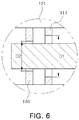
- FIG. 6 is a cross-sectional view illustrating a radial touch disc 140 in a magnetic bearing device 1 according to another exemplary embodiment in the present disclosure.
- the support unit 100 of the magnetic bearing device 1 may further include a housing 130 with which the magnetic support 110 and the sensor unit 120 are combined, and a radial touch disc 140 coupled to the housing 130 or an inner side of a radial magnetic member 111of the magnetic support 110.
- An interior diameter D2 of the radial touch disc 140 may be smaller than an interior diameter D1 of the radial magnetic member 111.
- the support unit 100 of the magnetic bearing device 1 may further include an axial touch disc 150 disposed between an axial magnetic member 112 of the magnetic support 110 and a stepped portion s of the roll shaft 2 and combined with the housing 130.
- the support unit 100 may include the radial touch disc 140 and the axial touch disc 150 to prevent the magnetic support 110 from colliding with the roll shaft 2.
- the magnetic support 110 and the sensor unit 120 may be combined to the housing 130.
- the housing 130 may include a housing body 131 as a base member.
- the housing body 131 may be combined with the magnetic support 110, the sensor unit 120, or the like.
- the housing body 131 may have a cylindrical shape so that the magnetic support 110, the sensor unit 120, or the like are combined therewith.
- the housing body 131 may include a stepped portion corresponding to a difference in diameters of the magnetic support 110, the sensor unit 120, and the like.
- the housing 130 may include a cable tube configured to electrically connect the magnetic support 110, the sensor unit 120, and the like to an external controller. That is, the cable tube may function to protect a control cable or communication cable connected to coils of the magnetic support 110 and the sensor unit 120 from a high temperature environment and the like.
- the housing 130 may further include a housing cover 133 to prevent the magnetic support 110 and the sensor unit 120 from moving out from the housing body 131 after the magnetic support 110 and the sensor unit 120 are combined with an inner side of the housing body 131.
- the housing cover 133 may be combined with an end of the housing body 131 having the cylindrical shape.
- a gasket g may be combined with the housing 130 to block inflow of an external material such as a hot-dip galvanizing material while combining the magnetic support 110 and the sensor unit 120 with the housing body 131.
- the radial touch disc 140 may function to prevent the radial magnetic member 111 of the magnetic support 110, which will described later, from colliding with the roll shaft 2.
- the radial touch disc 140 may come into contact with the roll shaft 2 before the radial magnetic member 111 comes into contact with the roll shaft 2, when no current is applied to the radial magnetic member 111 and thereby the magnetic field is not generated. Accordingly, the radial touch disc 140 may prevent the radial magnetic member 111 from colliding with the roll shaft 2.
- the interior diameter D2 of the radial touch disc 140 may be smaller than the interior diameter D1 of the radial magnetic member 111.
- the radial touch disc 140 may be combined with an inner side of the radial magnetic member 111, as illustrated in FIG. 5 .
- an outer side of the radial touch disc 140 may be combined with the housing 130, as illustrated in FIG. 6 .
- the radial touch disc 140 may be disposed adjacently to the radial magnetic member 111.
- the axial touch disc 150 may function to prevent the axial magnetic member 112 of the magnetic support 110, to be described later, from colliding with the roll shaft 2.
- the axial touch disc 150 may come into contact with the roll shaft 2 before the axial magnetic member 112 comes into contact with the roll shaft 2. Accordingly, collision between the axial magnetic member 112 and the roll shaft 2 may be prevented.
- the axial touch disc 150 may be combined with the housing 130 and disposed between the axial magnetic member 112 and the stepped portion s of the roll shaft 2.
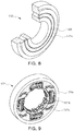
- FIG. 7 is a front view and a perspective view illustrating a radial magnetic member 111 of a magnetic support 110 in a magnetic bearing device 1 according to an exemplary embodiment in the present disclosure
- FIG. 8 is a perspective view illustrating an axial magnetic member 112 of a magnetic support 110 in a magnetic bearing device 1 according to an exemplary embodiment in the present disclosure
- FIG. 9 is a perspective view illustrating a sensor unit 120 in a magnetic bearing device 1 according to an exemplary embodiment in the present disclosure.
- the support unit 100 of the magnetic bearing device 1 may include the magnetic support 110 disposed adjacent to the roll shaft 2 and supporting the roll shaft 2 in at least one of an axial direction and a radial direction of the roll shaft 2, and the sensor unit 120 electrically connected to the magnetic support 110 and measuring and controlling the intensity of the vibration generated in the magnetic support 110.
- the support unit 100 may include the magnetic support 110 and the sensor unit 120 to support the roll shaft 2 by the magnetic force in a non-contact manner.
- the magnetic support 110 may form the magnetic field to support the roll shaft 2.
- the roll shaft 2 when the roll shaft 2 is formed of a magnetic material, the roll shaft 2 may be directly affected by the magnetic field generated in the magnetic support 110 and thereby polarized. Accordingly, the roll shaft 2 may be supported by an attractive force or a repulsive force.
- the roll shaft 2 may be supported by an interaction between the magnetic support 110 and the magnetic force receiving unit 200 since the magnetic force receiving unit 200 is combined with the roll shaft 2.
- the magnetic support 110 may include the radial magnetic member 111 supporting the roll shaft 2 in a radial direction of the roll shaft 2, and the axial magnetic member 112 supporting the roll shaft 2 in an axial direction of the roll shaft 2.
- the magnetic support 110 in the magnetic bearing device 1 may include the radial magnetic member 111 formed in a radial direction of the roll shaft 2 and supporting the roll shaft 2 in the radial direction of the roll shaft 2 when the roll shaft 2 rotates, and the axial magnetic member 112 disposed to face the roll shaft 2 or the stepped portion s formed on the axial sheathing member 230 of the magnetic force receiving unit 200 fitted on the roll shaft 2 in the axial direction and supporting the roll shaft 2 in the axial direction of the roll shaft 2 when the roll shaft 2 rotates.
- the radial magnetic member 111 may include a radial magnetic member body 111a, a radial core 111b, and a radial coil 111c to support the roll shaft 2 in the radial direction of the roll shaft 2.
- the radial magnetic member body 111a may be configured to surround the roll shaft 2 in a circumferential direction of the roll shaft 2, and combined with the housing 130.
- the radial core 111b may be formed at an inner side of the radial magnetic member body 111a.
- the radial core 111b may be formed at regular intervals on the inner side of the radial magnetic member body 111a, and the intervals may be adjusted, as needed.
- the radial coil 111c may be wound on the radial core 111b.
- the magnetic polarity of the radial core 111b may be alternately arranged in an N-S-N-S.
- the radial coil 111c may serve to generate the magnetic field by applying current.
- the radial coil 111c may be formed of ceramic-coated wires for high temperature so as to maintain performance of the magnetic force in a hot-dip galvanizing bath 4 at the high temperature of about 460 °C.
- the radial coil 111c may be connected to the outside through the cable tube or the like, so as to be protected from an external environment such as heat damage.
- the magnetic force of the radial magnetic member 111 may be proportional to the number of the radial core 111b, the number of windings of the radial coil 111c, and the applied current.
- the axial magnetic member 112 may include an axial magnetic member body 112a, an axial core and an axial coil 112b to support the roll shaft 2 in the axial direction of the roll shaft 2.
- the axial magnetic member body 112a may be formed to face the roll shaft 2 or the stepped portion s of the axial sheathing member 230. However, the axial touch disc 150 and the like may be disposed between the axial magnetic member body 112a and the stepped portion s.
- the axial magnetic member body 112a may be combined with the housing 130, and wound with the axial coil 112b.
- the axial coil 112b may wind along grooves formed on the axial magnetic member body 112a in a circumferential direction.
- the axial coil 112b may function to form the magnetic field by applying current.
- the axial coil 112b may be formed of ceramic-coated wires for high temperature so as to maintain performance of the magnetic force in the hot-dip galvanizing bath 4 at the high temperature of about 460 °C.
- the magnetic force of the axial magnetic member 112 may be proportional to the number of windings of the axial coil 112b and the applied current.
- the sensor unit 120 may function to adjust the amount of current applied to the magnetic support 110 by sensing vibrations generated in the radial direction or the axial direction of the roll shaft 2.
- the sensor unit 120 may include a sensor 121, a sensor cover 122, and a controller 123.
- the sensor 121 may function to sense the vibrations generated in the radial direction or the axial direction of the roll shaft 2.
- the sensor 121 may include a sensor body 121a configured to surround the roll shaft 2 in the circumferential direction, a sensor core 121b formed on an inner side of the sensor body 121a, and a sensor coil 121c winding the sensor core 121b.
- the sensor cover 122 may function to protect the sensor 121 from an external environment such as a high temperature.
- the sensor cover 122 may surround the sensor 121.
- the controller 123 may function to adjust the amount of the current applied to the magnetic support 110 by collecting vibration data from the sensor 121.
- the controller 123 may be integrated with the sensor body 121a, or externally formed and electrically connected to the sensor 121. In addition, the controller 123 may be electrically connected to the magnetic support 110 so as to control the magnetic support 110.
Landscapes
- Chemical & Material Sciences (AREA)
- Engineering & Computer Science (AREA)
- Mechanical Engineering (AREA)
- General Engineering & Computer Science (AREA)
- Organic Chemistry (AREA)
- Chemical Kinetics & Catalysis (AREA)
- Materials Engineering (AREA)
- Metallurgy (AREA)
- Physics & Mathematics (AREA)
- General Physics & Mathematics (AREA)
- Coating With Molten Metal (AREA)
- Rolls And Other Rotary Bodies (AREA)
- Magnetic Bearings And Hydrostatic Bearings (AREA)
- Electromagnetism (AREA)
Abstract
Description
- The present inventive concept relates to a magnetic bearing device and a hot-dip galvanizing apparatus including the magnetic bearing device.
- In a hot-dip galvanizing process, a steel sheet may be immersed in a galvanizing bath, filled with molten zinc via a snout, and may proceed in a vertical direction in a state of contact with a pot roll in the galvanizing bath, thereby being supported by the pot roll.
- The pot roll may be a sink roll or a stabilizing roll. Such a sink roll may function to change a moving direction of the steel sheet, and such a stabilizing roll may function to correct a shape of the steel sheet.
- In addition, mechanical contact is inevitable in a roll shaft bearing of a pot roll known in the art, which is rotated, for example, by rotating an axis of the bearing or by using ball bearings.
- When such a bearing is used in the galvanizing process, the bearing may be gradually abraded while the pot roll rotates in the hot-dip galvanizing bath, and vibrations and noise may occur due to unstable rotation.
- In addition, such contact-type bearings not only drastically shorten the lifespan thereof, but may also cause surface defects on a plated steel sheet, such as non-uniformity in plating thickness deviations, due to vibrations of the pot roll.
- Recently, non-contact type bearing devices such as magnetic bearing devices have been developed, in order to prevent problems of the contact type bearing devices as described above.
- Meanwhile, it is necessary to prevent a magnetic bearing device from colliding with a roll axis by maintaining a constant distance between the magnetic bearing device and the roll axis, for example.
- However, when magnetic force, generated to maintain a constant distance between the magnetic bearing device and the roll axis, is not precisely controlled, it may be difficult to prevent the magnetic bearing device from colliding with the roll axis.
- That is, when the magnetic bearing device is not precisely controlled, the lifespan of the magnetic bearing device may be shortened due to collisions with the roll axis.
- Further, the pot roll may be vibrated when collisions between the magnetic bearing device and the roll axis occur, since the magnetic bearing device may not be precisely controlled.
- In addition, surface defects, such as non-uniformity in plating thickness deviations, may occur in a plated steel sheet due to vibrations of the pot roll, similarly to those occurring in contact type bearing devices as described above.
- Accordingly, it is necessary to study a magnetic bearing device enabling such problems to be solved, and a hot-dip galvanizing apparatus including the magnetic bearing device.
- An aspect of the present inventive concept may provide a magnetic bearing device in which a support of a roll shaft is precisely controlled in a non-contact manner, and a hot-dip galvanizing apparatus including the magnetic bearing device.
- According to an aspect of the present inventive concept, a magnetic bearing device may include a support unit disposed adjacent to a roll shaft and generating a magnetic field toward the roll shaft, and a magnetic force receiving unit coupled to the roll shaft and only including a magnetic material in a portion facing the support unit, wherein the magnetic material is magnetized by the magnetic force.
- In addition, the magnetic force receiving unit of the magnetic bearing device may include a magnetic member formed of the magnetic material and disposed on the portion facing the support unit in the roll shaft, and a nonmagnetic member formed of a nonmagnetic material and disposed on a portion other than the portion on which the magnetic member is disposed on the roll shaft.
- In addition, the magnetic force receiving unit of the magnetic bearing device may further include an axial sheath member fitted onto the roll shaft and with which the magnetic member and the nonmagnetic member are combined.
- In addition, the magnetic member of the magnetic bearing device may have a cylindrical shape, and have the same width as the portion facing the support unit in the roll shaft.
- In addition, the magnetic member of the magnetic bearing device may have a disc shape, and the number of the magnetic member may correspond to a width of the portion facing the support unit in the roll shaft.
- In addition, the roll shaft of the magnetic bearing device may be formed of a nonmagnetic material.
- In addition, the support unit of the magnetic bearing device may include a magnetic support disposed adjacent to the roll shaft and supporting the roll shaft in at least one of an axial direction or a radial direction of the roll shaft, and a sensor electrically connected to the magnetic support to measure and control an intensity of vibrations of the magnetic support.
- In addition, the magnetic support of the magnetic bearing device may further include a radial magnetic member disposed in a radial direction of the roll shaft and supporting the roll shaft in the radial direction of the roll shaft when the roll shaft rotates, and an axial magnetic member disposed to face a stepped portion, formed in the roll shaft or the axial sheath member of the magnetic force receiving unit fitted on the roll shaft, in an axial direction of the roll shaft and supporting the roll shaft in the axial direction of the roll shaft when the roll shaft rotates.
- In addition, the support unit of the magnetic bearing device may further include a housing part with which the magnetic support and the sensor are combined, and a radial touch disc having a disc shape and combined with the housing part or an inner side of the radial magnetic member, wherein an internal diameter of the radial touch disc is smaller than an internal diameter of the radial magnetic member.
- In addition, the support unit of the magnetic bearing device may further include an axial touch disc combined with the housing part to be disposed between the axial magnetic member and the stepped portion of the roll shaft.
- In addition, the magnetic force receiving unit of the magnetic bearing device may include the magnetic material only on a portion facing the magnetic support and the sensor in the roll shaft.
- According to another aspect of the present inventive concept, a hot-dip galvanizing apparatus may include a galvanizing bath configured to accommodate molten zinc, a pot roll disposed on a transportation path of a steel sheet moving into the galvanizing bath, and the magnetic bearing device described above and disposed on a roll shaft of the pot roll.
- As set forth above, a magnetic bearing device and a hot-dip galvanizing apparatus including the magnetic bearing device according to an exemplary embodiment in the present disclosure can support a roll shaft in a non-contact manner.
- In particular, when the roll shaft is supported by magnetic force, the magnetic force can be controlled to only affect a portion to be supported in the roll shaft. Accordingly, the support of the roll shaft by the magnetic force can be precisely controlled in the magnetic bearing device and the hot-dip galvanizing apparatus including the magnetic bearing device according to the exemplary embodiment in the present disclosure.
- Since collisions between the
roll shaft 2 and the magnetic bearingdevice 1 are prevented, problems such as non-uniformity in plating thickness deviations caused by vibrations of the pot roll may be solved and quality of the steel sheet may be improved. -
-
FIG. 1 is a perspective view illustrating a hot-dip galvanizing apparatus according to an exemplary embodiment in the present disclosure; -
FIG. 2 is a cross-sectional view illustrating a magnetic bearing device according to an exemplary embodiment in the present disclosure; -
FIG. 3 is a side view illustrating a magnetic force receiving unit in a magnetic bearing device according to an exemplary embodiment in the present disclosure; -
FIG. 4 is an exploded perspective view of a magnetic force receiving unit in a magnetic bearing device according to an exemplary embodiment in the present disclosure; -
FIG. 5 is an exploded perspective view illustrating a magnetic force receiving unit in a magnetic bearing device according to an exemplary embodiment in the present disclosure; -
FIG. 6 is a cross-sectional view illustrating a radial touch disc in a magnetic bearing device according to another exemplary embodiment in the present disclosure; -
FIG. 7 is a front view and a perspective view illustrating a radial magnetic member of a magnetic support part in a magnetic bearing device according to an exemplary embodiment in the present disclosure; -
FIG. 8 is a perspective view illustrating an axial magnetic member of a magnetic support part in a magnetic bearing device according to an exemplary embodiment in the present disclosure; and -
FIG. 9 is a perspective view illustrating a sensor unit in a magnetic bearing device according to an exemplary embodiment in the present disclosure. - Hereinafter, exemplary embodiments of the present inventive concept will be described with reference to the accompanying drawings. The present inventive concept may, however, be exemplified in many different forms and should not be construed as being limited to the specific embodiments set forth herein. Those skilled in the art could easily suggest various embodiments, modifications, and equivalents falling within the scope of the present invention by adding, modifying, and deleting components.
- The same reference numbers will be used throughout this specification to refer to the same or like components.
- A magnetic bearing
device 1 and a hot-dip galvanizing apparatus including the magnetic bearingdevice 1 according to an exemplary embodiment in the present disclosure may support aroll shaft 2, and more specifically, may support theroll shaft 2 in a non-contact manner. - In particular, the magnetic bearing
device 1 and the hot-dip galvanizing apparatus including the magnetic bearingdevice 1 according to the exemplary embodiment in the present disclosure may support theroll shaft 2 with magnetic force. According to the exemplary embodiment in the present disclosure, the magnetic force may affect only a portion to be supported in theroll shaft 2, and thereby the support of theroll shaft 2 may be precisely controlled by the magnetic force. - Accordingly, since collisions between the
roll shaft 2 and the magnetic bearingdevice 1 are prevented, problems such as non-uniformity in plating thickness deviations caused by vibrations of the pot roll may be solved and quality of the steel sheet may be improved. -
FIG. 1 is a perspective view illustrating a hot-dip galvanizing apparatus according to an exemplary embodiment in the present disclosure. Referring toFIG. 1 , the hot-dip galvanizing apparatus according to the exemplary embodiment in the present disclosure may include a galvanizing bath 4 in which molten zinc is accommodated, a pot roll 3 disposed on a transportation path of the steel sheet moving into the galvanizing bath 4, and a magnetic bearingdevice 1, to be described later, disposed on theroll shaft 2 of the pot roll 3. - In this manner, the galvanizing bath 4 and the pot roll 3 may be provided to galvanize the steel sheet.
- Here, the pot roll 3 may include a sink roll configured to change a moving direction of the steel sheet, and a stabilizing roll configured to correct a shape of the steel sheet.
- In particular, since the hot-dip galvanizing apparatus according to the exemplary embodiment in the present disclosure includes the magnetic bearing
device 1, theroll shaft 2 of the pot roll 3 may be precisely supported. -
FIG. 2 is a cross-sectional view illustrating a magnetic bearingdevice 1 according to an exemplary embodiment in the present disclosure, andFIG. 3 is a side view illustrating a magneticforce receiving unit 200 of the magnetic bearingdevice 1 according to an exemplary embodiment in the present disclosure. - Referring to
FIGS. 2 and3 , the magnetic bearingdevice 1 according to the exemplary embodiment in the present disclosure may include asupport unit 100 disposed adjacent to theroll shaft 2 and generating a magnetic field toward theroll shaft 2, and a magneticforce receiving unit 200 coupled to theroll shaft 2. The magneticforce receiving unit 200 may include a magnetic material in only a portion facing thesupport unit 100, thereby being magnetized with magnetic force of the magnetic field generated in thesupport unit 100. - That is, since an effect of the magnetic force of the magnetic field generated in the
support unit 100 is concentrated on the portion of the magneticforce receiving unit 200 disposed on theroll shaft 2, the support of theroll shaft 2 may be precisely controlled. - The
support unit 100 may function to support theroll shaft 2 in a non-contact manner using the magnetic force. That is, thesupport unit 100 may generate the magnetic field, and support theroll shaft 2 by interaction with theroll shaft 2. - In this regard, the
support unit 100 may include amagnetic support 110 supporting theroll shaft 2 in at least one of an axial direction or a radial direction by the magnetic force, and asensor unit 120 for sensing vibrations. This will be described later in detail with reference toFIGS. 7 to 9 . - In addition, the
support unit 100 may include ahousing 130 with which themagnetic support 110 and thesensor unit 120 are combined, and aradial touch disc 140 and an axial touch disc 150 which serve to prevent collisions of themagnetic support 110 with theroll shaft 2. This will be described later in detail with reference toFIGS. 5 and6 . - Here, when the
roll shaft 2 is formed of a magnetic material, theroll shaft 2 may be directly affected by the magnetic field generated in thesupport unit 100 to be polarized and supported by an attractive force or a repulsive force. - In particular, even when the
roll shaft 2 is not formed of a magnetic material, theroll shaft 2 may be supported by the interaction between thesupport unit 100 and the magneticforce receiving unit 200 since the magneticforce receiving unit 200 to be described later, is coupled to theroll shaft 2. - That is, the
roll shaft 2 of themagnetic bearing device 1 according to the exemplary embodiment in the present disclosure may be formed of a nonmagnetic material. - In this manner, since the
roll shaft 2 is not affected by the magnetic field generated in thesupport unit 100 when theroll shaft 2 is formed of the nonmagnetic material, only the portion formed of the magnetic material in the magneticforce receiving unit 200, to be described later, may be affected by the magnetic field generated in thesupport unit 100. Accordingly, thesupport unit 100 may support theroll shaft 2 in more precisely controlled manner. - That is, when the
roll shaft 2 is formed of the magnetic material, an induced current formed by the magnetic force transmitted from a portion facing thesupport unit 100 in theroll shaft 2 or the magnetic field generated in thesupport unit 100 may affect the other portion of theroll shaft 2, resulting in a control error occurrence. - In addition, when the
roll shaft 2 is formed of a nonmagnetic material, a heat generation problem caused by the induced current formed by the magnetic force may be solved. - The magnetic
force receiving unit 200 may function to precisely control thesupport unit 100 to support theroll shaft 2, by concentrating the magnetic field generated in the support unit 10. - In this regard, the magnetic
force receiving unit 200 may include the magnetic material at only a portion facing thesupport unit 100 in theroll shaft 2. In such a manner, the magnetic force may be concentrated on the portion formed of the magnetic material in the magneticforce receiving unit 200 due to the interaction with the magnetic field generated in thesupport unit 100. - In particular, the portion formed of the magnetic material in the magnetic
force receiving unit 200 may be preferably disposed on a portion, facing themagnetic support 110 andsensor unit 120 of thesupport unit 100, in theroll shaft 2. Themagnetic support 110 andsensor unit 120 of thesupport unit 100 will be described later. - That is, the magnetic
force receiving unit 200 of themagnetic bearing device 1 according to the exemplary embodiment in the present disclosure may include amagnetic member 210 formed of the magnetic material, disposed only in the portion facing themagnetic support 110 andsensor unit 120, on theroll shaft 2. - This is because the
support unit 100 generates the magnetic force in a portion in which themagnetic support 110 and thesensor unit 120 face theroll shaft 2. - More specifically, the magnetic
force receiving unit 200 may include themagnetic member 210 and anonmagnetic member 220. - That is, the magnetic
force receiving unit 200 of themagnetic bearing device 1 according to the exemplary embodiment in the present disclosure may further include themagnetic member 210 formed of a magnetic material and disposed on the portion facing thesupport unit 100 in theroll shaft 2, and thenonmagnetic member 220 formed of a nonmagnetic material and disposed on a portion other than the portion on which the magnetic member is disposed, in the roll shaft. - Here, the magnetic material may include, for example, iron, cobalt, nickel, or a ferritic/martensitic stainless steel. In addition, the nonmagnetic material may include, for example, a non-metallic material such as a ceramic, or a metal, such as an austenite-based stainless steel.
- In addition, the
magnetic member 210 and thenonmagnetic member 220 may have a cylindrical shape or a disc shape so as to be coupled to theroll shaft 2. This will be described later in detail with reference toFIG. 4 . - Further, the magnetic
force receiving unit 200 may further include anaxial sheathing member 230 by which themagnetic member 210 and thenonmagnetic member 220 may be easily coupled to theroll shaft 2. - That is, the magnetic
force receiving unit 200 of themagnetic bearing device 1 according to the exemplary embodiment in the present disclosure may further include theaxial sheathing member 230 fitted to theroll shaft 2 and with which themagnetic member 210 and thenonmagnetic member 220 are combined. - The
axial sheathing member 230 may be provided since it may be difficult to couple themagnetic member 210 or thenonmagnetic member 220 to theroll shaft 2 when theroll shaft 2 does not have a rod shape having a constant diameter but a shape having diameters varying along its length. - That is, since only the inner side of the
axial sheathing member 230 is formed to have a shape corresponding to theroll shaft 2, it is not necessary to form themagnetic member 210 andnonmagnetic member 220 having different sizes. - Here, when the
roll shaft 2 is formed of a nonmagnetic material, theaxial sheathing member 230 may also be formed of a nonmagnetic material. Accordingly, the magnetic force may be effectively concentrated by the magneticforce receiving unit 200. -
FIG. 4 is an exploded perspective view illustrating a magneticforce receiving unit 200 of amagnetic bearing device 1 according to an exemplary embodiment in the present disclosure . Referring toFIG. 4 , themagnetic member 210 of themagnetic bearing device 1 according to the exemplary embodiment in the present disclosure may have a cylindrical shape. A width of themagnetic member 210 may be the same as a width of the portion facing thesupport unit 100 in theroll shaft 2. - In addition, the
magnetic member 210 of themagnetic bearing device 1 according to the exemplary embodiment in the present disclosure may have a disc shape, and the number of themagnetic member 210 may correspond to the width of the portion facing thesupport unit 100 in theroll shaft 2. - That is, the
magnetic member 210 and thenonmagnetic member 220 may have the cylindrical shape or the disc shape to be coupled to theroll shaft 2. - Here, when the
magnetic member 210 and thenonmagnetic member 220 have the cylindrical shape, themagnetic member 210 and thenonmagnetic member 220 may be easily coupled to theroll shaft 2. That is, the coupling may only be completed by inserting the cylindricalmagnetic member 210 having the same width as the portion facing thesupport unit 100 into theroll shaft 2, and the cylindricalnonmagnetic member 220 having the same width as a portion that does not face thesupport unit 100 in theroll shaft 2. - Meanwhile, when the
magnetic member 210 andnonmagnetic member 220 have a disc shape, it is advantageous that themagnetic member 210 and thenonmagnetic member 220 do not need to be manufactured every time that themagnetic member 210 andnonmagnetic member 220 are provided to thesupport unit 100 or rollshaft 2 having various shapes. That is, themagnetic member 210 may be stacked by a width equal to the width of the portion facing thesupport unit 100 in theroll shaft 2, to be coupled to theroll shaft 2, and thenonmagnetic member 220 may be stacked by a width equal to the width of the portion that does not face thesupport unit 100 in theroll shaft 2, to be coupled to theroll shaft 2. -
FIG. 5 is an exploded perspective view illustrating a magneticforce receiving unit 200 in amagnetic bearing device 1 according to an exemplary embodiment in the present disclosure, andFIG. 6 is a cross-sectional view illustrating aradial touch disc 140 in amagnetic bearing device 1 according to another exemplary embodiment in the present disclosure. - Referring to
FIGS. 5 and6 , thesupport unit 100 of themagnetic bearing device 1 according to the exemplary embodiment in the present disclosure may further include ahousing 130 with which themagnetic support 110 and thesensor unit 120 are combined, and aradial touch disc 140 coupled to thehousing 130 or an inner side of a radial magnetic member 111of themagnetic support 110. An interior diameter D2 of theradial touch disc 140 may be smaller than an interior diameter D1 of the radialmagnetic member 111. - In addition, the
support unit 100 of themagnetic bearing device 1 according to the exemplary embodiment in the present disclosure may further include an axial touch disc 150 disposed between an axialmagnetic member 112 of themagnetic support 110 and a stepped portion s of theroll shaft 2 and combined with thehousing 130. - That is, the
support unit 100 may include theradial touch disc 140 and the axial touch disc 150 to prevent themagnetic support 110 from colliding with theroll shaft 2. - The
magnetic support 110 and thesensor unit 120 may be combined to thehousing 130. In this regard, thehousing 130 may include ahousing body 131 as a base member. - That is, the
housing body 131 may be combined with themagnetic support 110, thesensor unit 120, or the like. In this regard, thehousing body 131 may have a cylindrical shape so that themagnetic support 110, thesensor unit 120, or the like are combined therewith. Thehousing body 131 may include a stepped portion corresponding to a difference in diameters of themagnetic support 110, thesensor unit 120, and the like. - Further, the
housing 130 may include a cable tube configured to electrically connect themagnetic support 110, thesensor unit 120, and the like to an external controller. That is, the cable tube may function to protect a control cable or communication cable connected to coils of themagnetic support 110 and thesensor unit 120 from a high temperature environment and the like. - In addition, the
housing 130 may further include ahousing cover 133 to prevent themagnetic support 110 and thesensor unit 120 from moving out from thehousing body 131 after themagnetic support 110 and thesensor unit 120 are combined with an inner side of thehousing body 131. Thehousing cover 133 may be combined with an end of thehousing body 131 having the cylindrical shape. - In addition, a gasket g may be combined with the
housing 130 to block inflow of an external material such as a hot-dip galvanizing material while combining themagnetic support 110 and thesensor unit 120 with thehousing body 131. - The
radial touch disc 140 may function to prevent the radialmagnetic member 111 of themagnetic support 110, which will described later, from colliding with theroll shaft 2. - That is, the
radial touch disc 140 may come into contact with theroll shaft 2 before the radialmagnetic member 111 comes into contact with theroll shaft 2, when no current is applied to the radialmagnetic member 111 and thereby the magnetic field is not generated. Accordingly, theradial touch disc 140 may prevent the radialmagnetic member 111 from colliding with theroll shaft 2. - In this regard, the interior diameter D2 of the
radial touch disc 140 may be smaller than the interior diameter D1 of the radialmagnetic member 111. - In addition, the
radial touch disc 140 may be combined with an inner side of the radialmagnetic member 111, as illustrated inFIG. 5 . - According to another exemplary embodiment in the present disclosure, an outer side of the
radial touch disc 140 may be combined with thehousing 130, as illustrated inFIG. 6 . Theradial touch disc 140 may be disposed adjacently to the radialmagnetic member 111. - The axial touch disc 150 may function to prevent the axial
magnetic member 112 of themagnetic support 110, to be described later, from colliding with theroll shaft 2. - That is, when no current is applied to the axial
magnetic member 112 and thereby, the magnetic field is not formed, the axial touch disc 150 may come into contact with theroll shaft 2 before the axialmagnetic member 112 comes into contact with theroll shaft 2. Accordingly, collision between the axialmagnetic member 112 and theroll shaft 2 may be prevented. - In this regard, the axial touch disc 150 may be combined with the
housing 130 and disposed between the axialmagnetic member 112 and the stepped portion s of theroll shaft 2. -
FIG. 7 is a front view and a perspective view illustrating a radialmagnetic member 111 of amagnetic support 110 in amagnetic bearing device 1 according to an exemplary embodiment in the present disclosure,FIG. 8 is a perspective view illustrating an axialmagnetic member 112 of amagnetic support 110 in amagnetic bearing device 1 according to an exemplary embodiment in the present disclosure, andFIG. 9 is a perspective view illustrating asensor unit 120 in amagnetic bearing device 1 according to an exemplary embodiment in the present disclosure. - Referring to
FIGS. 7 to 9 , thesupport unit 100 of themagnetic bearing device 1 according to the exemplary embodiment in the present disclosure may include themagnetic support 110 disposed adjacent to theroll shaft 2 and supporting theroll shaft 2 in at least one of an axial direction and a radial direction of theroll shaft 2, and thesensor unit 120 electrically connected to themagnetic support 110 and measuring and controlling the intensity of the vibration generated in themagnetic support 110. - That is, the
support unit 100 may include themagnetic support 110 and thesensor unit 120 to support theroll shaft 2 by the magnetic force in a non-contact manner. - The
magnetic support 110 may form the magnetic field to support theroll shaft 2. - Here, when the
roll shaft 2 is formed of a magnetic material, theroll shaft 2 may be directly affected by the magnetic field generated in themagnetic support 110 and thereby polarized. Accordingly, theroll shaft 2 may be supported by an attractive force or a repulsive force. - In particular, even when the
roll shaft 2 is not formed of a magnetic material, theroll shaft 2 may be supported by an interaction between themagnetic support 110 and the magneticforce receiving unit 200 since the magneticforce receiving unit 200 is combined with theroll shaft 2. - In this regard, the
magnetic support 110 may include the radialmagnetic member 111 supporting theroll shaft 2 in a radial direction of theroll shaft 2, and the axialmagnetic member 112 supporting theroll shaft 2 in an axial direction of theroll shaft 2. - That is, the
magnetic support 110 in themagnetic bearing device 1 according to the exemplary embodiment in the present disclosure may include the radialmagnetic member 111 formed in a radial direction of theroll shaft 2 and supporting theroll shaft 2 in the radial direction of theroll shaft 2 when theroll shaft 2 rotates, and the axialmagnetic member 112 disposed to face theroll shaft 2 or the stepped portion s formed on theaxial sheathing member 230 of the magneticforce receiving unit 200 fitted on theroll shaft 2 in the axial direction and supporting theroll shaft 2 in the axial direction of theroll shaft 2 when theroll shaft 2 rotates. - The radial
magnetic member 111 may include a radialmagnetic member body 111a, aradial core 111b, and aradial coil 111c to support theroll shaft 2 in the radial direction of theroll shaft 2. - The radial
magnetic member body 111a may be configured to surround theroll shaft 2 in a circumferential direction of theroll shaft 2, and combined with thehousing 130. In addition, theradial core 111b may be formed at an inner side of the radialmagnetic member body 111a. - The
radial core 111b may be formed at regular intervals on the inner side of the radialmagnetic member body 111a, and the intervals may be adjusted, as needed. In addition, theradial coil 111c may be wound on theradial core 111b. Here, the magnetic polarity of theradial core 111b may be alternately arranged in an N-S-N-S. - The
radial coil 111c may serve to generate the magnetic field by applying current. Theradial coil 111c may be formed of ceramic-coated wires for high temperature so as to maintain performance of the magnetic force in a hot-dip galvanizing bath 4 at the high temperature of about 460 °C. - In addition, the
radial coil 111c may be connected to the outside through the cable tube or the like, so as to be protected from an external environment such as heat damage. - Here, the magnetic force of the radial
magnetic member 111 may be proportional to the number of theradial core 111b, the number of windings of theradial coil 111c, and the applied current. - The axial
magnetic member 112 may include an axialmagnetic member body 112a, an axial core and anaxial coil 112b to support theroll shaft 2 in the axial direction of theroll shaft 2. - The axial
magnetic member body 112a may be formed to face theroll shaft 2 or the stepped portion s of theaxial sheathing member 230. However, the axial touch disc 150 and the like may be disposed between the axialmagnetic member body 112a and the stepped portion s. - In addition, the axial
magnetic member body 112a may be combined with thehousing 130, and wound with theaxial coil 112b. - The
axial coil 112b may wind along grooves formed on the axialmagnetic member body 112a in a circumferential direction. - The
axial coil 112b may function to form the magnetic field by applying current. Theaxial coil 112b may be formed of ceramic-coated wires for high temperature so as to maintain performance of the magnetic force in the hot-dip galvanizing bath 4 at the high temperature of about 460 °C. - Here, the magnetic force of the axial
magnetic member 112 may be proportional to the number of windings of theaxial coil 112b and the applied current. - The
sensor unit 120 may function to adjust the amount of current applied to themagnetic support 110 by sensing vibrations generated in the radial direction or the axial direction of theroll shaft 2. In this regard, thesensor unit 120 may include asensor 121, a sensor cover 122, and a controller 123. - The
sensor 121 may function to sense the vibrations generated in the radial direction or the axial direction of theroll shaft 2. In this regard, thesensor 121 may include asensor body 121a configured to surround theroll shaft 2 in the circumferential direction, asensor core 121b formed on an inner side of thesensor body 121a, and asensor coil 121c winding thesensor core 121b. - The sensor cover 122 may function to protect the
sensor 121 from an external environment such as a high temperature. In this regard, the sensor cover 122 may surround thesensor 121. - The controller 123 may function to adjust the amount of the current applied to the
magnetic support 110 by collecting vibration data from thesensor 121. The controller 123 may be integrated with thesensor body 121a, or externally formed and electrically connected to thesensor 121. In addition, the controller 123 may be electrically connected to themagnetic support 110 so as to control themagnetic support 110.
Claims (12)
- A magnetic bearing device, comprising:a support unit disposed adjacent to a roll shaft and generating a magnetic field toward the roll shaft; anda magnetic force receiving unit coupled to the roll shaft and only including a magnetic material in a portion facing the support unit, wherein the magnetic material is magnetized by the magnetic force.
- The magnetic bearing device of claim 1, wherein the magnetic force receiving unit comprises:a magnetic member formed of the magnetic material and disposed on the portion facing the support unit in the roll shaft; anda nonmagnetic member formed of a nonmagnetic material and disposed on a portion other than the portion on which the magnetic member is disposed, in the roll shaft.
- The magnetic bearing device of claim 2, wherein the magnetic force receiving unit further comprises an axial sheath member fitted onto the roll shaft and with which the magnetic member and the nonmagnetic member are combined.
- The magnetic bearing device of claim 2, wherein the magnetic member has a cylindrical shape, and has the same width as the portion facing the support unit in the roll shaft.
- The magnetic bearing device of claim 2, wherein the magnetic member has a disc shape, and the number of the magnetic member corresponds to a width of the portion facing the support unit in the roll shaft.
- The magnetic bearing device of claim 1, wherein the roll shaft is formed of a nonmagnetic material.
- The magnetic bearing device of claim 1, wherein the support unit comprises:a magnetic support disposed adjacent to the roll shaft and supporting the roll shaft in at least one of an axial direction or a radial direction of the roll shaft; anda sensor electrically connected to the magnetic support to measure and control an intensity of vibrations of the magnetic support.
- The magnetic bearing device of claim 7, wherein the magnetic support comprises:a radial magnetic member disposed in a radial direction of the roll shaft and supporting the roll shaft in the radial direction of the roll shaft when the roll shaft rotates; andan axial magnetic member disposed to face a stepped portion, formed in the roll shaft or in an axial sheath member of the magnetic force receiving unit fitted on the roll shaft, in an axial direction of the roll shaft and supporting the roll shaft in the axial direction of the roll shaft when the roll shaft rotates.
- The magnetic bearing device of claim 8, wherein the support unit further comprises:a housing part with which the magnetic support and the sensor are combined; anda radial touch disc having a disc shape and combined with the housing part or an inner side of the radial magnetic member, wherein an internal diameter of the radial touch disc is smaller than an internal diameter of the radial magnetic member.
- The magnetic bearing device of claim 9, wherein the support unit further comprises:
an axial touch disc combined with the housing part to be disposed between the axial magnetic member and the stepped portion of the roll shaft. - The magnetic bearing device of claim 7, wherein the magnetic force receiving unit includes the magnetic material only on a portion facing the magnetic support and the sensor in the roll shaft.
- A hot-dip galvanizing apparatus, comprising:a galvanizing bath configured to accommodate molten zinc;a pot roll disposed on a transportation path of a steel sheet moving into the galvanizing bath; anda magnetic bearing device as claimed in any one of claims 1 to 11, wherein the magnetic bearing device is disposed on a roll shaft of the pot roll.
Applications Claiming Priority (2)
| Application Number | Priority Date | Filing Date | Title |
|---|---|---|---|
| KR1020150119744A KR101795857B1 (en) | 2015-08-25 | 2015-08-25 | Magnetic bearing apparatus and hot dip galvanizing apparatus having thereof |
| PCT/KR2015/010362 WO2017034068A1 (en) | 2015-08-25 | 2015-10-01 | Magnetic bearing device and hot-dip galvanizing apparatus comprising same |
Publications (2)
| Publication Number | Publication Date |
|---|---|
| EP3343052A1 true EP3343052A1 (en) | 2018-07-04 |
| EP3343052A4 EP3343052A4 (en) | 2018-08-01 |
Family
ID=58100695
Family Applications (1)
| Application Number | Title | Priority Date | Filing Date |
|---|---|---|---|
| EP15902340.7A Withdrawn EP3343052A4 (en) | 2015-08-25 | 2015-10-01 | Magnetic bearing device and hot-dip galvanizing apparatus comprising same |
Country Status (7)
| Country | Link |
|---|---|
| US (1) | US20180245192A1 (en) |
| EP (1) | EP3343052A4 (en) |
| JP (1) | JP6622904B2 (en) |
| KR (1) | KR101795857B1 (en) |
| CN (1) | CN107923438B (en) |
| MX (1) | MX2018002348A (en) |
| WO (1) | WO2017034068A1 (en) |
Families Citing this family (4)
| Publication number | Priority date | Publication date | Assignee | Title |
|---|---|---|---|---|
| CN111118427B (en) * | 2018-10-31 | 2022-06-28 | 宝山钢铁股份有限公司 | A method for reducing friction and wear of bearing pair of hot-dip galvanized sunken roller |
| US11939656B2 (en) | 2020-05-22 | 2024-03-26 | Cleveland-Cliffs Steel Properties Inc. | Snout for use in a hot dip coating line |
| US11898251B2 (en) | 2020-05-22 | 2024-02-13 | Cleveland-Cliffs Steel Properties Inc. | Snout for use in a hot dip coating line |
| US12365030B2 (en) * | 2020-09-29 | 2025-07-22 | The Boeing Company | Multi-property monolithic stainless steel component |
Family Cites Families (13)
| Publication number | Priority date | Publication date | Assignee | Title |
|---|---|---|---|---|
| US4383498A (en) * | 1979-03-14 | 1983-05-17 | Hitachi Metals, Ltd. | Apparatus for applying magnetic toner to a magnetic transport roll |
| JP3733160B2 (en) * | 1995-06-05 | 2006-01-11 | 光洋精工株式会社 | Magnetic bearing device |
| DE20006302U1 (en) * | 2000-04-06 | 2001-10-25 | Band-Zink-GmbH, 40764 Langenfeld | Coating device |
| JP2002339970A (en) * | 2001-05-15 | 2002-11-27 | Ebara Corp | Magnetic bearing device, and turbo-molecular pump |
| JP2003161321A (en) * | 2001-11-26 | 2003-06-06 | Mitsubishi Heavy Ind Ltd | Posture control system of rotating device |
| KR100513205B1 (en) * | 2002-03-21 | 2005-09-08 | 한국전기연구원 | Radial Magnetic Bearing With Increased Axial Guidance Force |
| WO2005039019A1 (en) * | 2003-10-15 | 2005-04-28 | Rigaku Corporation | Actuator |
| ATE421647T1 (en) * | 2005-08-24 | 2009-02-15 | Mecos Traxler Ag | ROTOR SHAFT FOR A MAGNETIC BEARING DEVICE |
| DE102006053734A1 (en) * | 2006-11-15 | 2008-05-21 | Oerlikon Textile Gmbh & Co. Kg | Rotor drive of an open-end spinning device |
| KR20100105802A (en) * | 2007-04-19 | 2010-09-29 | 콘서트 파마슈티컬즈, 인크. | Deuterated morpholinyl compound |
| JP5192271B2 (en) * | 2008-03-31 | 2013-05-08 | 川崎重工業株式会社 | Magnetic bearing device |
| KR101568422B1 (en) * | 2009-05-06 | 2015-11-12 | 주식회사 포스코 | Magnetic bearing device for supporting roll shaft |
| EP2994654B1 (en) * | 2013-05-09 | 2018-02-28 | Dresser-Rand Company | Magnetic bearing protection device |
-
2015
- 2015-08-25 KR KR1020150119744A patent/KR101795857B1/en active Active
- 2015-10-01 US US15/754,813 patent/US20180245192A1/en not_active Abandoned
- 2015-10-01 EP EP15902340.7A patent/EP3343052A4/en not_active Withdrawn
- 2015-10-01 WO PCT/KR2015/010362 patent/WO2017034068A1/en not_active Ceased
- 2015-10-01 MX MX2018002348A patent/MX2018002348A/en unknown
- 2015-10-01 CN CN201580082667.3A patent/CN107923438B/en not_active Expired - Fee Related
- 2015-10-01 JP JP2018510054A patent/JP6622904B2/en active Active
Also Published As
| Publication number | Publication date |
|---|---|
| CN107923438A (en) | 2018-04-17 |
| US20180245192A1 (en) | 2018-08-30 |
| JP6622904B2 (en) | 2019-12-18 |
| MX2018002348A (en) | 2018-04-11 |
| KR20170024647A (en) | 2017-03-08 |
| CN107923438B (en) | 2020-03-20 |
| EP3343052A4 (en) | 2018-08-01 |
| KR101795857B1 (en) | 2017-11-09 |
| WO2017034068A1 (en) | 2017-03-02 |
| JP2018532080A (en) | 2018-11-01 |
Similar Documents
| Publication | Publication Date | Title |
|---|---|---|
| US20180245192A1 (en) | Magnetic bearing device and hot-dip galvanizing apparatus including the same | |
| JP6437586B2 (en) | Measuring probe for measuring the thickness of a thin layer and method for manufacturing a sensor element of a measuring probe | |
| US10084361B2 (en) | Motor | |
| US9059625B2 (en) | Linear vibration device having spring | |
| US10539533B2 (en) | Wire rope flaw detection device and adjustment jig | |
| US9809413B2 (en) | Winding device for strand shaped winding material | |
| JP2013544973A (en) | Steel plate stabilizer | |
| US9964147B2 (en) | Magnetic bearing, shaft and shaft monitoring for a spinning rotor of an open-end spinning machine | |
| JP2009002464A (en) | Magnetic bearing device and machine tool equipped with the same | |
| JP5799837B2 (en) | Surface treatment jig | |
| US20230182213A1 (en) | Boring bar with electrodynamic actuators for counteracting vibrations and machine tool provided with such a bar | |
| CN103423321B (en) | Temporary support component including its sensing subelement and bearing assembly | |
| JP2013185951A (en) | Magnetic flaw detection probe | |
| US20140125191A1 (en) | Vibration dampening structure for stepper motors | |
| CN103423320B (en) | Temporary support component including its sensing subelement and bearing assembly | |
| JP2009020048A (en) | Contact sensor | |
| JP2008108763A (en) | Magnetizing apparatus and magnetizing method | |
| KR20190074628A (en) | Apparatus for stablizing wire and apparatus for hot dipping including having same | |
| CN106702106B (en) | High frequency Equipment for Heating Processing | |
| JP4899761B2 (en) | Magnet body magnetizing method and magnetizing apparatus | |
| JP6361517B2 (en) | Roll rotation speed detection device | |
| JP2015068757A (en) | Rotation sensor, motor equipped with the rotation sensor, and rotation detection method | |
| JP2013185952A (en) | Magnetic flaw detection probe | |
| JP2007225691A (en) | OA roller manufacturing method | |
| JP2006163816A (en) | Contactless signal transmission device |
Legal Events
| Date | Code | Title | Description |
|---|---|---|---|
| PUAI | Public reference made under article 153(3) epc to a published international application that has entered the european phase |
Free format text: ORIGINAL CODE: 0009012 |
|
| 17P | Request for examination filed |
Effective date: 20180321 |
|
| AK | Designated contracting states |
Kind code of ref document: A1 Designated state(s): AL AT BE BG CH CY CZ DE DK EE ES FI FR GB GR HR HU IE IS IT LI LT LU LV MC MK MT NL NO PL PT RO RS SE SI SK SM TR |
|
| AX | Request for extension of the european patent |
Extension state: BA ME |
|
| A4 | Supplementary search report drawn up and despatched |
Effective date: 20180628 |
|
| RIC1 | Information provided on ipc code assigned before grant |
Ipc: C23C 2/06 20060101ALI20180622BHEP Ipc: C23C 2/40 20060101AFI20180622BHEP Ipc: G01H 17/00 20060101ALI20180622BHEP Ipc: F16C 13/02 20060101ALI20180622BHEP Ipc: C23C 2/00 20060101ALI20180622BHEP Ipc: F16C 32/04 20060101ALI20180622BHEP Ipc: C23C 2/14 20060101ALI20180622BHEP |
|
| DAV | Request for validation of the european patent (deleted) | ||
| DAX | Request for extension of the european patent (deleted) | ||
| 17Q | First examination report despatched |
Effective date: 20200122 |
|
| STAA | Information on the status of an ep patent application or granted ep patent |
Free format text: STATUS: THE APPLICATION IS DEEMED TO BE WITHDRAWN |
|
| 18D | Application deemed to be withdrawn |
Effective date: 20200603 |