EP3343028A1 - System and method for determining torque on a wind turbine shaft - Google Patents
System and method for determining torque on a wind turbine shaft Download PDFInfo
- Publication number
- EP3343028A1 EP3343028A1 EP17209776.8A EP17209776A EP3343028A1 EP 3343028 A1 EP3343028 A1 EP 3343028A1 EP 17209776 A EP17209776 A EP 17209776A EP 3343028 A1 EP3343028 A1 EP 3343028A1
- Authority
- EP
- European Patent Office
- Prior art keywords
- fluid
- gearbox
- pressure sensor
- fluid conduit
- pressure
- Prior art date
- Legal status (The legal status is an assumption and is not a legal conclusion. Google has not performed a legal analysis and makes no representation as to the accuracy of the status listed.)
- Granted
Links
Images


Classifications
-
- F—MECHANICAL ENGINEERING; LIGHTING; HEATING; WEAPONS; BLASTING
- F03—MACHINES OR ENGINES FOR LIQUIDS; WIND, SPRING, OR WEIGHT MOTORS; PRODUCING MECHANICAL POWER OR A REACTIVE PROPULSIVE THRUST, NOT OTHERWISE PROVIDED FOR
- F03D—WIND MOTORS
- F03D17/00—Monitoring or testing of wind motors, e.g. diagnostics
-
- F—MECHANICAL ENGINEERING; LIGHTING; HEATING; WEAPONS; BLASTING
- F03—MACHINES OR ENGINES FOR LIQUIDS; WIND, SPRING, OR WEIGHT MOTORS; PRODUCING MECHANICAL POWER OR A REACTIVE PROPULSIVE THRUST, NOT OTHERWISE PROVIDED FOR
- F03D—WIND MOTORS
- F03D7/00—Controlling wind motors
- F03D7/02—Controlling wind motors the wind motors having rotation axis substantially parallel to the air flow entering the rotor
- F03D7/0296—Controlling wind motors the wind motors having rotation axis substantially parallel to the air flow entering the rotor to prevent, counteract or reduce noise emissions
-
- F—MECHANICAL ENGINEERING; LIGHTING; HEATING; WEAPONS; BLASTING
- F03—MACHINES OR ENGINES FOR LIQUIDS; WIND, SPRING, OR WEIGHT MOTORS; PRODUCING MECHANICAL POWER OR A REACTIVE PROPULSIVE THRUST, NOT OTHERWISE PROVIDED FOR
- F03D—WIND MOTORS
- F03D1/00—Wind motors with rotation axis substantially parallel to the air flow entering the rotor
-
- F—MECHANICAL ENGINEERING; LIGHTING; HEATING; WEAPONS; BLASTING
- F03—MACHINES OR ENGINES FOR LIQUIDS; WIND, SPRING, OR WEIGHT MOTORS; PRODUCING MECHANICAL POWER OR A REACTIVE PROPULSIVE THRUST, NOT OTHERWISE PROVIDED FOR
- F03D—WIND MOTORS
- F03D15/00—Transmission of mechanical power
-
- F—MECHANICAL ENGINEERING; LIGHTING; HEATING; WEAPONS; BLASTING
- F03—MACHINES OR ENGINES FOR LIQUIDS; WIND, SPRING, OR WEIGHT MOTORS; PRODUCING MECHANICAL POWER OR A REACTIVE PROPULSIVE THRUST, NOT OTHERWISE PROVIDED FOR
- F03D—WIND MOTORS
- F03D7/00—Controlling wind motors
-
- F—MECHANICAL ENGINEERING; LIGHTING; HEATING; WEAPONS; BLASTING
- F03—MACHINES OR ENGINES FOR LIQUIDS; WIND, SPRING, OR WEIGHT MOTORS; PRODUCING MECHANICAL POWER OR A REACTIVE PROPULSIVE THRUST, NOT OTHERWISE PROVIDED FOR
- F03D—WIND MOTORS
- F03D7/00—Controlling wind motors
- F03D7/02—Controlling wind motors the wind motors having rotation axis substantially parallel to the air flow entering the rotor
- F03D7/0204—Controlling wind motors the wind motors having rotation axis substantially parallel to the air flow entering the rotor for orientation in relation to wind direction
-
- F—MECHANICAL ENGINEERING; LIGHTING; HEATING; WEAPONS; BLASTING
- F03—MACHINES OR ENGINES FOR LIQUIDS; WIND, SPRING, OR WEIGHT MOTORS; PRODUCING MECHANICAL POWER OR A REACTIVE PROPULSIVE THRUST, NOT OTHERWISE PROVIDED FOR
- F03D—WIND MOTORS
- F03D7/00—Controlling wind motors
- F03D7/02—Controlling wind motors the wind motors having rotation axis substantially parallel to the air flow entering the rotor
- F03D7/022—Adjusting aerodynamic properties of the blades
- F03D7/0224—Adjusting blade pitch
-
- F—MECHANICAL ENGINEERING; LIGHTING; HEATING; WEAPONS; BLASTING
- F03—MACHINES OR ENGINES FOR LIQUIDS; WIND, SPRING, OR WEIGHT MOTORS; PRODUCING MECHANICAL POWER OR A REACTIVE PROPULSIVE THRUST, NOT OTHERWISE PROVIDED FOR
- F03D—WIND MOTORS
- F03D7/00—Controlling wind motors
- F03D7/02—Controlling wind motors the wind motors having rotation axis substantially parallel to the air flow entering the rotor
- F03D7/0272—Controlling wind motors the wind motors having rotation axis substantially parallel to the air flow entering the rotor by measures acting on the electrical generator
-
- F—MECHANICAL ENGINEERING; LIGHTING; HEATING; WEAPONS; BLASTING
- F03—MACHINES OR ENGINES FOR LIQUIDS; WIND, SPRING, OR WEIGHT MOTORS; PRODUCING MECHANICAL POWER OR A REACTIVE PROPULSIVE THRUST, NOT OTHERWISE PROVIDED FOR
- F03D—WIND MOTORS
- F03D13/00—Assembly, mounting or commissioning of wind motors; Arrangements specially adapted for transporting wind motor components
- F03D13/20—Arrangements for mounting or supporting wind motors; Masts or towers for wind motors
-
- F—MECHANICAL ENGINEERING; LIGHTING; HEATING; WEAPONS; BLASTING
- F05—INDEXING SCHEMES RELATING TO ENGINES OR PUMPS IN VARIOUS SUBCLASSES OF CLASSES F01-F04
- F05B—INDEXING SCHEME RELATING TO WIND, SPRING, WEIGHT, INERTIA OR LIKE MOTORS, TO MACHINES OR ENGINES FOR LIQUIDS COVERED BY SUBCLASSES F03B, F03D AND F03G
- F05B2260/00—Function
- F05B2260/40—Transmission of power
- F05B2260/403—Transmission of power through the shape of the drive components
- F05B2260/4031—Transmission of power through the shape of the drive components as in toothed gearing
- F05B2260/40311—Transmission of power through the shape of the drive components as in toothed gearing of the epicyclic, planetary or differential type
-
- F—MECHANICAL ENGINEERING; LIGHTING; HEATING; WEAPONS; BLASTING
- F05—INDEXING SCHEMES RELATING TO ENGINES OR PUMPS IN VARIOUS SUBCLASSES OF CLASSES F01-F04
- F05B—INDEXING SCHEME RELATING TO WIND, SPRING, WEIGHT, INERTIA OR LIKE MOTORS, TO MACHINES OR ENGINES FOR LIQUIDS COVERED BY SUBCLASSES F03B, F03D AND F03G
- F05B2260/00—Function
- F05B2260/96—Preventing, counteracting or reducing vibration or noise
-
- F—MECHANICAL ENGINEERING; LIGHTING; HEATING; WEAPONS; BLASTING
- F05—INDEXING SCHEMES RELATING TO ENGINES OR PUMPS IN VARIOUS SUBCLASSES OF CLASSES F01-F04
- F05B—INDEXING SCHEME RELATING TO WIND, SPRING, WEIGHT, INERTIA OR LIKE MOTORS, TO MACHINES OR ENGINES FOR LIQUIDS COVERED BY SUBCLASSES F03B, F03D AND F03G
- F05B2260/00—Function
- F05B2260/96—Preventing, counteracting or reducing vibration or noise
- F05B2260/964—Preventing, counteracting or reducing vibration or noise by damping means
-
- F—MECHANICAL ENGINEERING; LIGHTING; HEATING; WEAPONS; BLASTING
- F05—INDEXING SCHEMES RELATING TO ENGINES OR PUMPS IN VARIOUS SUBCLASSES OF CLASSES F01-F04
- F05B—INDEXING SCHEME RELATING TO WIND, SPRING, WEIGHT, INERTIA OR LIKE MOTORS, TO MACHINES OR ENGINES FOR LIQUIDS COVERED BY SUBCLASSES F03B, F03D AND F03G
- F05B2270/00—Control
- F05B2270/10—Purpose of the control system
- F05B2270/103—Purpose of the control system to affect the output of the engine
- F05B2270/1032—Torque
-
- F—MECHANICAL ENGINEERING; LIGHTING; HEATING; WEAPONS; BLASTING
- F05—INDEXING SCHEMES RELATING TO ENGINES OR PUMPS IN VARIOUS SUBCLASSES OF CLASSES F01-F04
- F05B—INDEXING SCHEME RELATING TO WIND, SPRING, WEIGHT, INERTIA OR LIKE MOTORS, TO MACHINES OR ENGINES FOR LIQUIDS COVERED BY SUBCLASSES F03B, F03D AND F03G
- F05B2270/00—Control
- F05B2270/30—Control parameters, e.g. input parameters
-
- F—MECHANICAL ENGINEERING; LIGHTING; HEATING; WEAPONS; BLASTING
- F05—INDEXING SCHEMES RELATING TO ENGINES OR PUMPS IN VARIOUS SUBCLASSES OF CLASSES F01-F04
- F05B—INDEXING SCHEME RELATING TO WIND, SPRING, WEIGHT, INERTIA OR LIKE MOTORS, TO MACHINES OR ENGINES FOR LIQUIDS COVERED BY SUBCLASSES F03B, F03D AND F03G
- F05B2270/00—Control
- F05B2270/30—Control parameters, e.g. input parameters
- F05B2270/335—Output power or torque
-
- Y—GENERAL TAGGING OF NEW TECHNOLOGICAL DEVELOPMENTS; GENERAL TAGGING OF CROSS-SECTIONAL TECHNOLOGIES SPANNING OVER SEVERAL SECTIONS OF THE IPC; TECHNICAL SUBJECTS COVERED BY FORMER USPC CROSS-REFERENCE ART COLLECTIONS [XRACs] AND DIGESTS
- Y02—TECHNOLOGIES OR APPLICATIONS FOR MITIGATION OR ADAPTATION AGAINST CLIMATE CHANGE
- Y02E—REDUCTION OF GREENHOUSE GAS [GHG] EMISSIONS, RELATED TO ENERGY GENERATION, TRANSMISSION OR DISTRIBUTION
- Y02E10/00—Energy generation through renewable energy sources
- Y02E10/70—Wind energy
- Y02E10/72—Wind turbines with rotation axis in wind direction
Definitions
- the present disclosure generally relates to wind turbines. More particularly, the present disclosure relates to systems and methods for determining torque exerted on shafts of wind turbines.
- Wind power is considered one of the cleanest, most environmentally friendly energy sources presently available, and wind turbines have gained increased attention in this regard.
- a modern wind turbine typically includes a tower, a nacelle mounted on the tower, a generator positioned in the nacelle, and one or more rotor blades.
- the one or more rotor blades convert kinetic energy of wind into mechanical energy using known airfoil principles.
- a drivetrain transmits the mechanical energy from the rotor blades to the generator.
- the generator then converts the mechanical energy to electrical energy that may be supplied to a utility grid.
- the drivetrain may include a gearbox, a rotor shaft, and a generator shaft. More specifically, the rotor shaft may rotatably couple the rotor blades to the gearbox. The generator shaft may rotatably couple the gearbox to the generator. In this respect, the drivetrain and, in particular, the gearbox may allow the generator to rotate at a different speed than the rotor blades.
- the rotor blades exert torque on the rotor shaft.
- the magnitude of the torque exerted on the rotor shaft may be useful in determining various operating and performance characteristics of the wind turbine.
- the torque exerted on the rotor shaft may be used when determining the wind speed, the load on a drivetrain of the wind turbine, the electrical power generated by the wind turbine, and/or the power losses occurring in the wind turbine.
- Conventional systems and methods for determining the torque exerted on the rotor shaft may provide unreliable torque determinations. For example, some conventional systems and methods determine the torque exerted on the rotor shaft based on measurements taken from the generator. These systems and method do not account for losses in the gearbox and are prone to error. Systems and methods that use strain gauges placed on the rotor shaft to determine the torque exerted thereon are also inaccurate. Furthermore, determining the torque on the rotor shaft based off of electrical characteristics of the wind turbine (e.g., measured electrical power) is also unreliable.
- the present disclosure is directed to a system for determining a torque exerted on a shaft of a wind turbine.
- the system includes a gearbox coupled to the shaft.
- the gearbox includes a first arm and a second arm.
- First and second fluid dampers respectively couple to the first and second arms of the gearbox.
- a first fluid conduit fluidly couples the first and second fluid dampers.
- a first pressure sensor is in operative association with the first fluid conduit to detect a fluid pressure of fluid within the first fluid conduit.
- a controller communicatively couples to the first pressure sensor. The controller is configured to determine the torque exerted on the shaft based on signals received from the first pressure sensor.
- the present disclosure is directed to a wind turbine.
- the wind turbine includes a tower, a nacelle mounted on the tower, and a rotor coupled to the nacelle.
- the rotor includes a hub and at least one rotor blade extending from the hub.
- a gearbox is positioned within the nacelle and includes first and second arms.
- a gearbox mount couples the gearbox to the nacelle.
- a shaft rotatably couples the rotor and the gearbox.
- First and second fluid dampers respectively couple the first and second arms of the gearbox to a gearbox mount.
- a first fluid conduit fluidly couples the first and second fluid dampers.
- a first pressure sensor is in operative association with the first fluid conduit to detect a fluid pressure of a fluid within the first fluid conduit.
- a controller communicatively couples to the first pressure sensor. The controller is configured to determine the torque exerted on the shaft based on signals received from the first pressure sensor.
- the present disclosure is directed to a method for determining a torque exerted on a shaft of a wind turbine.
- the method includes measuring, with a first pressure sensor, an operating fluid pressure of fluid in a first fluid conduit fluidly coupling first and second fluid dampers that support a gearbox relative to a gearbox mount.
- the method also includes receiving, with a controller, a signal from the first pressure sensor. The signal is associated with the operating fluid pressure within the first fluid conduit.
- the method further includes determining, with the controller, the torque exerted on the shaft based on the operating fluid pressure within the first fluid conduit.
- FIG. 1 illustrates a perspective view of one embodiment of an exemplary wind turbine 10 in accordance with the present disclosure.
- the wind turbine 10 generally includes a tower 12 extending from a support surface 14, a nacelle 16 mounted on the tower 12, and a rotor 18 coupled to the nacelle 16.
- the rotor 18 includes a rotatable hub 20 and at least one rotor blade 22 coupled to and extending outwardly from the hub 20.
- the rotor 18 includes three rotor blades 22. In alternative embodiments, however, the rotor 18 may include more or less than three rotor blades 22.
- Each rotor blade 22 may be spaced about the hub 20 to facilitate rotating the rotor 18 to convert kinetic energy from the wind into usable rotational, mechanical energy.
- a generator 24 positioned in the nacelle 16 may generate electrical power from the rotational energy of the rotor 18.
- a drivetrain 26 rotatably couples the rotor 18 to the electric generator 24.
- the drivetrain 26 may include a rotor shaft 28 that rotatably couples the hub 20 of the rotor 18 to a gearbox assembly 30.
- the gearbox assembly 30 may be supported by and coupled to a bedplate 32 in the nacelle 16.
- the drivetrain 26 may also include a generator shaft 34 that rotatably couples the gearbox assembly 30 to the generator 24.
- rotation of the rotor 18 drives the generator 24.
- the rotor shaft 28 may provide a low speed, high torque input to the gearbox assembly 30 in response to rotation of the rotor blades 22 and the hub 20.
- the gearbox assembly 30 may then convert the low speed, high torque input to a high speed, low torque output to drive the generator shaft 34 and, thus, the generator 24.
- the generator 24 may be directly rotatably coupled to the rotor shaft 28 in a direct-drive configuration.
- the wind turbine 10 may also include a turbine control system or a turbine controller 36.
- the turbine controller 36 is disposed within a control cabinet 38 mounted to a portion of the nacelle 16. In alternate embodiments, however, the turbine controller 36 may be disposed at any location on or in the wind turbine 10, at any location on the support surface 14, or any other suitable location.
- the turbine controller 36 may be communicatively coupled to various components of the wind turbine 10 for generally controlling the wind turbine 10 and/or such components.
- the turbine controller 36 may be communicatively coupled to the yaw drive mechanism 40 for controlling a yaw direction of the nacelle 16 relative to a wind direction 42 ( FIG. 1 ).
- the turbine controller 36 may be configured to transmit a control signal to the the yaw drive mechanism 40 such that an electric motor or other suitable actuator 44 of the yaw drive mechanism 40 rotates the nacelle 16 about a yaw axis 46 ( FIG. 1 ).
- the turbine controller 36 may also be communicatively coupled to one or more pitch adjustment mechanisms 48 (one of which is shown in FIG.
- the turbine controller 36 may be configured to transmit a control signal to each pitch adjustment mechanism 48 such that an electric motor or other suitable actuator 52 of each pitch adjustment mechanism 48 rotates each blade 22 about a corresponding pitch axis 54 ( FIG. 1 ) relative to the hub 20.
- FIG. 3 illustrates a system 100 for determining a torque exerted on the rotor shaft 28 of the wind turbine 10.
- the system 100 includes a gearbox assembly 102 that may be incorporated into the wind turbine 10 in place of or in addition to the gearbox assembly 30.
- the rotor 18 exerts torque on the rotor shaft 28 as the wind turbine 10 operates.
- a fluid pressure within various fluid dampers in the gearbox assembly 102 may be used to determine the torque exerted on the rotor shaft 28.
- the gearbox assembly 102 includes a gearbox 104. More specifically, the gearbox 104 includes a gearbox housing 106 that contains a gear set 108.
- the gear set 108 engages the rotor shaft 28 as an input and the generator shaft 34 as an output.
- the gear set 108 may allow the rotor shaft 28 and the generator shaft 34 to rotate at different speeds.
- the generator shaft 34 may operate at a higher rotational speed that the rotor shaft 28.
- the gear set 108 may be any suitable type of gear set (e.g., a planetary gear set) and/or include any suitable type of gears (e.g., spur gears, helical gears, etc.).
- the gearbox 104 also includes a first arm 110 and a second arm 112 extending outward from opposing sides of the gearbox housing 106.
- the first arm 110 includes a top surface 114 and a bottom surface 116.
- the second arm 112 includes a top surface 118 and a bottom surface 120.
- the gearbox assembly 102 also includes a gearbox mount 122 for coupling the gearbox 104 to the bedplate 32.
- the gearbox mount 122 includes a first gearbox mount portion 124 and a second gearbox mount portion 126.
- the first gearbox mount portion 124 may include a base wall 128 that couples to the bedplate 32, a side wall 130 coupled to the base wall 128, and a top wall 132 coupled to the side wall 130 and oriented parallel to the base wall 128.
- the second gearbox mount portion 126 may include a base wall 134 that couples to the bedplate 32, a side wall 136 coupled to the base wall 134, and a top wall 138 coupled to the side wall 136 and oriented parallel to the base wall 134.
- the first and second gearbox mount portions 124, 126 may be separate components or a single component.
- the gearbox mount 122 may have suitable structure for coupling the gearbox 104 to the bedplate 32.
- various fluid dampers may support the gearbox 104 relative to the gearbox mount 122. More specifically, a first fluid damper 140 may couple, such as directly connect, the first arm 110 (e.g., the top surface 114 of the first arm 110) to the top wall 132 of the first gearbox mount portion 124. A second fluid damper 142 may couple, such as directly connect, the second arm 112 (e.g., the bottom surface 120 of the second arm 112) to the base wall 134 of the second gearbox mount portion 126. A third fluid damper 144 may couple, such as directly connect, the first arm 110 (e.g., the bottom surface 116 of the first arm 110) to the base wall 128 of the first gearbox mount portion 124.
- a fourth fluid damper 146 may couple, such as directly connect, the second arm 112 (e.g., the top surface 118 of the second arm 112) to the top wall 138 of the second gearbox mount portion 126.
- each fluid damper 140, 142, 144, 146 may include a cylinder containing a fluid and a piston slidably positioned within the cylinder such that the fluid damps the movement of the piston. Alternate embodiments may include more or fewer fluid dampers.
- springs may couple the fluid dampers 140, 142, 144, 146 to the gearbox mount 122.
- a first spring 148 may couple, such as directly connect, the first fluid damper 140 to the top surface 132 of the first gearbox mount portion 124.
- a second spring 150 may couple, such as directly connect, the second fluid damper 142 to the bottom surface 134 of the second gearbox mount portion 126.
- a third spring 152 may couple, such as directly connect, the third fluid damper 144 to the bottom surface 128 of the first gearbox mount portion 124.
- a fourth spring 154 may couple, such as directly connect, the fourth fluid damper 146 to the top surface 138 of the second gearbox mount portion 126.
- the fluid dampers 140, 142, 144, 146 may couple directly to the gearbox mount 122.
- additional springs may be positioned in parallel with the fluid dampers 140, 142, 144, 146 to further support the gearbox 104 relative to the gearbox mount 122. More specifically, a fifth spring 156 may couple the first arm 110 (e.g., the top surface 114 of the first arm 110) to the top wall 132 of the first gearbox mount portion 124. A sixth spring 158 may couple the second arm 112 (e.g., the bottom surface 120 of the second arm 112) to the base wall 134 of the second gearbox mount portion 126. A seventh spring 160 may couple the first arm 110 (e.g., the bottom surface 116 of the first arm 110) to the base wall 128 of the first gearbox mount portion 124.
- a fifth spring 156 may couple the first arm 110 (e.g., the top surface 114 of the first arm 110) to the top wall 132 of the first gearbox mount portion 124.
- a sixth spring 158 may couple the second arm 112 (e.g., the bottom surface 120 of the second arm 112) to
- An eighth spring 162 may couple the second arm 112 (e.g., the top surface 118 of the second arm 112) to the top wall 138 of the second gearbox mount portion 126.
- the springs 156, 158, 160, 162 may be positioned between the side walls 130, 136 and the fluid dampers 140, 142, 144, 146 or between the fluid dampers 140, 142, 144, 146 and the gearbox housing 106.
- alternate embodiments may more or fewer springs (including zero springs).
- the fluid dampers 140, 142, 144, 146 may be fluidly connected, such as directly connected, by various fluid conduits that permit fluid flow therebetween . More specifically, the fluid conduits fluidly couple fluid dampers 140, 142, 144, 146 located on opposite sides of the gearbox 104. In this respect, and as shown in FIG. 3 , a first fluid conduit 164 may fluidly couple the first and second fluid dampers 140, 142. As such, fluid may flow between the first and second fluid dampers 140, 142. Similarly, a second fluid conduit 166 may fluidly couple third and fourth fluid dampers 144, 146. Accordingly, fluid may flow between the third and fourth fluid dampers 144, 146.
- the first fluid conduit 164 is fluidly isolated from the second fluid conduit 166. That is, the fluid may not be able to flow between the first and second fluid conduits 164, 166.
- the fluid may be a water and glycol mixture. In alternate embodiments, the fluid may be any suitable fluid.
- the rotor 18 exerts a torque on the rotor shaft 28 during operation of the wind turbine 10.
- This torque causes the rotor shaft 28 to rotate, thereby driving the gearbox 104, the generator shaft 32 (if included), and the generator 24.
- the rotation of the rotor shaft 28, exerts torque on the gearbox 104.
- at least some of the various fluid dampers 140, 142, 144, 146 resist the torque exerted on the gearbox 104, thereby preventing the gearbox 104 from rotating relative to the gearbox mount 122.
- Some or all of the springs 148, 150, 152, 154, 156, 158, 160, 162, if included, may further resist torque exerted the gearbox 104.
- the first and second fluid dampers 140, 142 may at least partially resist the torque exerted on the gearbox 104. More specifically, the rotor shaft 28 may rotate in a rotation direction indicated by an arrow 167, thereby exerting a torque on the gearbox 104 acting in the same direction.
- the fluid pressure in the first and second dampers 140, 142 and the first fluid conduit 164 increases to counteract the torque exerted on the gearbox 104 by the rotor shaft 28.
- fluid chambers of the first and second fluid dampers 140, 142 may shrink in such instances, thereby increasing the fluid pressure therein.
- the fluid pressure in the first fluid conduit 164 is related to or otherwise associated with the torque exerted on the rotor shaft 28.
- fluid pressure in the first fluid conduit 164 increases as the torque exerted on the rotor shaft 28 increases.
- the fluid pressure in the third and fourth conduits 144, 146 and the second fluid conduit 166 decreases when torque is exerted on the gearbox 104.
- fluid chambers of the third and fourth fluid dampers 144, 146 may expand, thereby decreasing the fluid pressure therein.
- the rotor shaft 28 may rotate in a rotation direction opposite to the arrow 167.
- the third and fourth fluid dampers 144, 146 and the second fluid conduit 166 may experience an increase in fluid pressure to counteract the torque exerted on the rotor shaft 28.
- the first and second fluid dampers 140, 142 and the first fluid conduit 164 may experience a decrease in fluid pressure.
- the system 100 may also include a pressure sensor in operative association with one of the fluid conduits 164, 166.
- the pressure sensor is in operative association with the fluid conduit 164, 166 experiencing the increase in fluid pressure when torque is exerted on the rotor shaft 28.
- the system 100 includes a first pressure sensor 168 in operative association with the first fluid conduit 164.
- the first pressure sensor 168 detects a fluid pressure of fluid within the first fluid conduit 164.
- the first pressure sensor 168 is in fluid communication with the first fluid conduit 164.
- the fluid pressure of fluid in the first fluid conduit 164 may correspond to or otherwise be associated with the torque exerted on the rotor shaft 28.
- the first pressure sensor 168 may be a pressure transducer or any other suitable type of pressure sensor. In alternate embodiments, however, the first pressure sensor 168 may be in operative association with the second fluid conduit 166.
- the system 100 may include a controller 170 communicatively coupled to one or more components of the system 100, such as the first pressure sensor 168.
- the controller 170 may correspond to the turbine controller 26 of the wind turbine 10.
- the controller 170 may be a separate processing device of the wind turbine 10 in addition to the turbine controller 26.
- the controller 170 may comprise any suitable processor-based device known in the art, such as a computing device or any suitable combination of computing devices.
- the controller 170 may include one or more processor(s) 172 and associated memory device(s) 174 configured to perform a variety of computer-implemented functions.
- processor refers not only to integrated circuits referred to in the art as being included in a computer, but also refers to a controller, a microcontroller, a microcomputer, a programmable logic controller (PLC), an application specific integrated circuit, and other programmable circuits.
- the memory device(s) 174 of the controller 170 may generally comprise memory element(s) including, but not limited to, computer readable medium (e.g., random access memory (RAM)), computer readable non-volatile medium (e.g., a flash memory), a floppy disk, a compact disc-read only memory (CD-ROM), a magnetooptical disk (MOD), a digital versatile disc (DVD) and/or other suitable memory elements.
- Such memory device(s) 174 may generally be configured to store suitable computer-readable instructions that, when implemented by the processor(s) 172, configure the controller 170 to perform various computer-implemented functions, such as one or more aspects of the method 200 described below with reference to FIG. 5 .
- the controller 170 may also include various other suitable components, such as a communications circuit or module, one or more input/output channels, a data/control bus and/or the like.
- the controller 170 is communicatively coupled to the first pressure sensor 168.
- the controller 170 may be communicatively coupled to the first pressure sensor 168 via a wired or wireless connection.
- measurement signals e.g., indicated by dashed line 176 in FIG. 3
- the controller 170 may then be configured to determine the torque on the rotor shaft 28 based on the measurement signals 176 received from the first pressure sensor 168.
- the controller 170 may include a look-up table or suitable mathematical formula stored within its memory 174 that correlates the fluid pressure measurements to the torque exerted on the rotor shaft 28.
- FIG. 4 illustrates an alternative embodiment of the system 100.
- the system 100 may also include a pressure sensor in operative association with each of the fluid conduits 164, 166.
- the system 100 includes the first pressure sensor 168 in operative association with the first fluid conduit 164 as discussed in greater detail above.
- the system 100 also includes a second pressure sensor 178 in operative association with the second fluid conduit 166.
- the second pressure sensor 178 detects a fluid pressure of fluid within the second fluid conduit 164.
- the second pressure sensor 178 is in fluid communication with the second fluid conduit 166.
- the fluid pressure of fluid in the first fluid conduit 164 and/or the second fluid conduit 166 may correspond to or otherwise be associated with the torque exerted on the rotor shaft 28.
- the second pressure sensor 178 may be a pressure transducer or any other suitable type of pressure sensor.
- the controller 170 may be communicatively coupled to the second pressure sensor 178.
- the controller 170 may be communicatively coupled to the second pressure sensor 178 via a wired or wireless connection.
- measurement signals e.g., indicated by dashed line 180 in FIG. 4
- the controller 170 may then be configured to determine the torque on the rotor shaft 28 based on the measurement signals 176 received from the first pressure sensor 168 and/or the measurement signals 180 received from the second pressure sensor 178 (e.g., via suitable mathematical functions or a look-up table).
- both measurement signals 176, 180 may be used together to determine the torque on the rotor shaft 28.
- a first measurement signal (e.g., the measurement signals 176) may be used to determine the torque on the rotor shaft 28 during normal operation of the wind turbine 10.
- a second measurement signal (e.g., the measurement signal 180) may be used only when, e.g., the first measurement signal is outside of a predetermined range or the controller 170 fails to receive the first measurement signal.
- FIG. 5 illustrates a method 200 for determining a torque exerted on a shaft of a wind turbine in accordance with embodiments of the present disclosure.
- the method 200 will be described below in the context of determining the torque exerted on the rotor shaft 28 of the wind turbine 10. Nevertheless, the method 200 maybe used to determine torque on any shaft of any wind turbine.
- the first pressure sensor 168 may measure a base line fluid pressure in the first fluid conduit 164.
- the base line fluid pressure may be the fluid pressure in the first fluid conduit 164 when no torque is exerted on the rotor shaft 28 (e.g., when the wind turbine 10 is not in operation). That is, the baseline fluid pressure is measured when the first and second fluid dampers 140, 142 are not resisting torque exerted on the gearbox 104.
- the controller 170 may then receive the measurement signals 176 from the first pressure sensor 168 indicative of the base line fluid pressure. As will be discussed below, the controller 170 may use the base line fluid pressure when determining the torque exerted on the rotor shaft 28.
- the second pressure sensor 178 may measure a base line fluid pressure in the second fluid conduit 166. In alternate embodiments, the step 202 may not be performed.
- one or more actuators may adjust the rotor blades 22 of the wind turbine 10 to permit the rotor 18 to exert torque on the rotor shaft 28.
- the actuator 52 of each pitch adjustment mechanism 50 may rotate the corresponding rotor blade 22 about its pitch axis 54 to position the rotor blade 22 in an orientation that allows the rotor 18 to exert torque on the rotor shaft 28.
- a tip speed ratio of the rotor blades 22 may be adjusted by adjusting the torque of the generator 23 to extract maximum power.
- the actuator 44 of the yaw drive mechanism 40 may rotate the nacelle 16 about the yaw axis 46 to position the nacelle 16 in an orientation that allows the rotor 18 to exert torque on the rotor shaft 28.
- step 204 may not be performed.
- the first pressure sensor 168 measures an operating fluid pressure of fluid in the first fluid conduit 164.
- step 206 is performed when torque is exerted on the rotor shaft 28 (e.g., when the wind turbine 10 is operating). That is, the operating fluid pressure is measured when the first and second fluid dampers 140, 142 are resisting torque exerted on the gearbox 104.
- the second pressure sensor 178 may measure an operating fluid pressure of fluid in the second fluid conduit 166. In such embodiments, the operating fluid pressure in the first fluid conduit 164 may be independent of the operating fluid pressure in the second fluid conduit 166.
- the controller 170 receives a signal associated with the operating fluid pressure within the first fluid conduit 164 (e.g., the measurement signals 176). In some embodiments, the controller 170 may also receive a signal associated with the operating fluid pressure within the second fluid conduit 166 (e.g., the measurement signals 180).
- the controller 170 may determine the torque exerted on the rotor shaft 28 based on the operating fluid pressure within the first fluid conduit 164.
- the fluid pressure in the first fluid conduit 164 may correspond to or otherwise be associated with the torque exerted on the rotor shaft 28.
- the controller 170 may determine the torque exerted on the rotor shaft 28 using a suitable look-up table or mathematical function.
- the controller 170 may use the base line fluid pressure in the first fluid conduit 164 when determining the torque exerted on the rotor shaft 28.
- the controller 170 may determine the torque exerted on the rotor shaft 28 based on the operating fluid pressure within the second fluid conduit 166 in lieu of or in addition to using the operating fluid pressure within the first fluid conduit 164.
- the system 100 and method 200 disclosed herein determine the torque exerted on the rotor shaft 28 based on the fluid pressure in the first fluid conduit 164 coupling the first and second fluid dampers 140, 142. More specifically, the torque exerted on the rotor shaft 28 is transferred to the gearbox 104. The first and second fluid dampers 140, 142 resist this torque to prevent the gearbox 104 from rotating. As such, the fluid pressure in in the first fluid conduit 164 corresponds to the torque exerted on the rotor shaft 28. In this respect, determining the torque exerted on the rotor shaft 28 using fluid pressure in the first fluid conduit 164 results in more accurate results due to unaccounted power losses in the gearbox 104 and the electrical system. In this respect, the system 100 and the method 200 provide more reliable determinations of the torque exerted on the rotor shaft 28 than conventional systems and methods.
Landscapes
- Engineering & Computer Science (AREA)
- Life Sciences & Earth Sciences (AREA)
- Sustainable Development (AREA)
- Sustainable Energy (AREA)
- Chemical & Material Sciences (AREA)
- Combustion & Propulsion (AREA)
- Mechanical Engineering (AREA)
- General Engineering & Computer Science (AREA)
- Physics & Mathematics (AREA)
- Fluid Mechanics (AREA)
- Wind Motors (AREA)
Abstract
Description
- The present disclosure generally relates to wind turbines. More particularly, the present disclosure relates to systems and methods for determining torque exerted on shafts of wind turbines.
- Wind power is considered one of the cleanest, most environmentally friendly energy sources presently available, and wind turbines have gained increased attention in this regard. A modern wind turbine typically includes a tower, a nacelle mounted on the tower, a generator positioned in the nacelle, and one or more rotor blades. The one or more rotor blades convert kinetic energy of wind into mechanical energy using known airfoil principles. A drivetrain transmits the mechanical energy from the rotor blades to the generator. The generator then converts the mechanical energy to electrical energy that may be supplied to a utility grid.
- The drivetrain may include a gearbox, a rotor shaft, and a generator shaft. More specifically, the rotor shaft may rotatably couple the rotor blades to the gearbox. The generator shaft may rotatably couple the gearbox to the generator. In this respect, the drivetrain and, in particular, the gearbox may allow the generator to rotate at a different speed than the rotor blades.
- During operation of the wind turbine, the rotor blades exert torque on the rotor shaft. The magnitude of the torque exerted on the rotor shaft may be useful in determining various operating and performance characteristics of the wind turbine. For example, the torque exerted on the rotor shaft may be used when determining the wind speed, the load on a drivetrain of the wind turbine, the electrical power generated by the wind turbine, and/or the power losses occurring in the wind turbine.
- Conventional systems and methods for determining the torque exerted on the rotor shaft may provide unreliable torque determinations. For example, some conventional systems and methods determine the torque exerted on the rotor shaft based on measurements taken from the generator. These systems and method do not account for losses in the gearbox and are prone to error. Systems and methods that use strain gauges placed on the rotor shaft to determine the torque exerted thereon are also inaccurate. Furthermore, determining the torque on the rotor shaft based off of electrical characteristics of the wind turbine (e.g., measured electrical power) is also unreliable.
- Accordingly, improved wind turbines, and, in particular, improved systems and methods for determining the torque exerted on wind turbine shafts, are desired in the art. Specifically, systems and methods that produce relatively more reliable torque determinations would be advantageous.
- Various aspects and advantages of the technology will be set forth in part in the following description, or may be clear from the description, or may be learned through practice of the technology.
- In one embodiment, the present disclosure is directed to a system for determining a torque exerted on a shaft of a wind turbine. The system includes a gearbox coupled to the shaft. The gearbox includes a first arm and a second arm. First and second fluid dampers respectively couple to the first and second arms of the gearbox. A first fluid conduit fluidly couples the first and second fluid dampers. A first pressure sensor is in operative association with the first fluid conduit to detect a fluid pressure of fluid within the first fluid conduit. A controller communicatively couples to the first pressure sensor. The controller is configured to determine the torque exerted on the shaft based on signals received from the first pressure sensor.
- In another embodiment, the present disclosure is directed to a wind turbine. The wind turbine includes a tower, a nacelle mounted on the tower, and a rotor coupled to the nacelle. The rotor includes a hub and at least one rotor blade extending from the hub. A gearbox is positioned within the nacelle and includes first and second arms. A gearbox mount couples the gearbox to the nacelle. A shaft rotatably couples the rotor and the gearbox. First and second fluid dampers respectively couple the first and second arms of the gearbox to a gearbox mount. A first fluid conduit fluidly couples the first and second fluid dampers. A first pressure sensor is in operative association with the first fluid conduit to detect a fluid pressure of a fluid within the first fluid conduit. A controller communicatively couples to the first pressure sensor. The controller is configured to determine the torque exerted on the shaft based on signals received from the first pressure sensor.
- In a further embodiment, the present disclosure is directed to a method for determining a torque exerted on a shaft of a wind turbine. The method includes measuring, with a first pressure sensor, an operating fluid pressure of fluid in a first fluid conduit fluidly coupling first and second fluid dampers that support a gearbox relative to a gearbox mount. The method also includes receiving, with a controller, a signal from the first pressure sensor. The signal is associated with the operating fluid pressure within the first fluid conduit. The method further includes determining, with the controller, the torque exerted on the shaft based on the operating fluid pressure within the first fluid conduit.
- Vrious features, aspects and advantages of the present technology will become better understood with reference to the following description and appended claims. The accompanying drawings, which are incorporated in and constitute a part of this specification, illustrate embodiments of the technology and, together with the description, serve to explain the principles of the technology.
- In the drawings:
-
FIG. 1 is a perspective view of a wind turbine in accordance with embodiments of the present disclosure; -
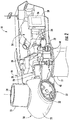
FIG. 2 is a perspective, internal view of a nacelle of a wind turbine in accordance with embodiments of the present disclosure; -
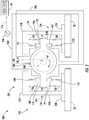
FIG. 3 is a schematic view of an embodiment of a system for determining a torque exerted on a shaft of a wind turbine in accordance with embodiments of the present disclosure; -
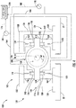
FIG. 4 is a schematic view of an alternate embodiment of a system for determining a torque exerted on a shaft of a wind turbine in accordance with embodiments of the present disclosure; and -
FIG. 5 is a flow chart illustrating a method for determining a torque exerted on a shaft of a wind turbine in accordance with embodiments of the present disclosure. - Repeat use of reference characters in the present specification and drawings is intended to represent the same or analogous features or elements of the present technology.
- Reference will now be made in detail to present embodiments of the technology, one or more examples of which are illustrated in the accompanying drawings. The detailed description uses numerical and letter designations to refer to features in the drawings. Like or similar designations in the drawings and description have been used to refer to like or similar parts of the technology. As used herein, the terms "first", "second", and "third" may be used interchangeably to distinguish one component from another and are not intended to signify location or importance of the individual components.
- Each example is provided by way of explanation of the technology, not limitation of the technology. In fact, it will be apparent to those skilled in the art that modifications and variations can be made in the present technology without departing from the scope or spirit thereof. For instance, features illustrated or described as part of one embodiment may be used on another embodiment to yield a still further embodiment. Thus, it is intended that the present technology covers such modifications and variations as come within the scope of the appended claims and their equivalents.
- Referring now to the drawings,
FIG. 1 illustrates a perspective view of one embodiment of anexemplary wind turbine 10 in accordance with the present disclosure. As shown, thewind turbine 10 generally includes atower 12 extending from asupport surface 14, anacelle 16 mounted on thetower 12, and arotor 18 coupled to thenacelle 16. Therotor 18 includes arotatable hub 20 and at least onerotor blade 22 coupled to and extending outwardly from thehub 20. For example, in the embodiment shown inFIG. 1 , therotor 18 includes threerotor blades 22. In alternative embodiments, however, therotor 18 may include more or less than threerotor blades 22. Eachrotor blade 22 may be spaced about thehub 20 to facilitate rotating therotor 18 to convert kinetic energy from the wind into usable rotational, mechanical energy. Agenerator 24 positioned in thenacelle 16 may generate electrical power from the rotational energy of therotor 18. - Referring now to
FIG. 2 , adrivetrain 26 rotatably couples therotor 18 to theelectric generator 24. As shown, thedrivetrain 26 may include arotor shaft 28 that rotatably couples thehub 20 of therotor 18 to agearbox assembly 30. Thegearbox assembly 30 may be supported by and coupled to abedplate 32 in thenacelle 16. Thedrivetrain 26 may also include agenerator shaft 34 that rotatably couples thegearbox assembly 30 to thegenerator 24. In this respect, rotation of therotor 18 drives thegenerator 24. More specifically, therotor shaft 28 may provide a low speed, high torque input to thegearbox assembly 30 in response to rotation of therotor blades 22 and thehub 20. Thegearbox assembly 30 may then convert the low speed, high torque input to a high speed, low torque output to drive thegenerator shaft 34 and, thus, thegenerator 24. In alternate embodiments, however, thegenerator 24 may be directly rotatably coupled to therotor shaft 28 in a direct-drive configuration. - The
wind turbine 10 may also include a turbine control system or aturbine controller 36. In the embodiment shown inFIG. 2 , for example, theturbine controller 36 is disposed within acontrol cabinet 38 mounted to a portion of thenacelle 16. In alternate embodiments, however, theturbine controller 36 may be disposed at any location on or in thewind turbine 10, at any location on thesupport surface 14, or any other suitable location. - The
turbine controller 36 may be communicatively coupled to various components of thewind turbine 10 for generally controlling thewind turbine 10 and/or such components. In certain embodiments, theturbine controller 36 may be communicatively coupled to theyaw drive mechanism 40 for controlling a yaw direction of thenacelle 16 relative to a wind direction 42 (FIG. 1 ). For example, theturbine controller 36 may be configured to transmit a control signal to the theyaw drive mechanism 40 such that an electric motor or othersuitable actuator 44 of theyaw drive mechanism 40 rotates thenacelle 16 about a yaw axis 46 (FIG. 1 ). Furthermore, theturbine controller 36 may also be communicatively coupled to one or more pitch adjustment mechanisms 48 (one of which is shown inFIG. 2 ) for controlling a pitch angle of therotor blades 22 relative to thewind direction 42. For example, theturbine controller 36 may be configured to transmit a control signal to each pitch adjustment mechanism 48 such that an electric motor or othersuitable actuator 52 of each pitch adjustment mechanism 48 rotates eachblade 22 about a corresponding pitch axis 54 (FIG. 1 ) relative to thehub 20. -
FIG. 3 illustrates asystem 100 for determining a torque exerted on therotor shaft 28 of thewind turbine 10. As shown, thesystem 100 includes agearbox assembly 102 that may be incorporated into thewind turbine 10 in place of or in addition to thegearbox assembly 30. As will be discussed in greater detail below, therotor 18 exerts torque on therotor shaft 28 as thewind turbine 10 operates. A fluid pressure within various fluid dampers in thegearbox assembly 102 may be used to determine the torque exerted on therotor shaft 28. - As shown in
FIG. 3 , thegearbox assembly 102 includes agearbox 104. More specifically, thegearbox 104 includes agearbox housing 106 that contains agear set 108. The gear set 108 engages therotor shaft 28 as an input and thegenerator shaft 34 as an output. In this respect, the gear set 108 may allow therotor shaft 28 and thegenerator shaft 34 to rotate at different speeds. For example, thegenerator shaft 34 may operate at a higher rotational speed that therotor shaft 28. The gear set 108 may be any suitable type of gear set (e.g., a planetary gear set) and/or include any suitable type of gears (e.g., spur gears, helical gears, etc.). Thegearbox 104 also includes afirst arm 110 and asecond arm 112 extending outward from opposing sides of thegearbox housing 106. Thefirst arm 110 includes atop surface 114 and abottom surface 116. Similarly, thesecond arm 112 includes atop surface 118 and abottom surface 120. - The
gearbox assembly 102 also includes agearbox mount 122 for coupling thegearbox 104 to thebedplate 32. In the embodiment shown inFIG. 3 , thegearbox mount 122 includes a firstgearbox mount portion 124 and a secondgearbox mount portion 126. The firstgearbox mount portion 124 may include abase wall 128 that couples to thebedplate 32, aside wall 130 coupled to thebase wall 128, and atop wall 132 coupled to theside wall 130 and oriented parallel to thebase wall 128. Similarly, the secondgearbox mount portion 126 may include abase wall 134 that couples to thebedplate 32, aside wall 136 coupled to thebase wall 134, and atop wall 138 coupled to theside wall 136 and oriented parallel to thebase wall 134. The first and secondgearbox mount portions gearbox mount 122 may have suitable structure for coupling thegearbox 104 to thebedplate 32. - As shown in
FIG. 3 , various fluid dampers may support thegearbox 104 relative to thegearbox mount 122. More specifically, a firstfluid damper 140 may couple, such as directly connect, the first arm 110 (e.g., thetop surface 114 of the first arm 110) to thetop wall 132 of the firstgearbox mount portion 124. A secondfluid damper 142 may couple, such as directly connect, the second arm 112 (e.g., thebottom surface 120 of the second arm 112) to thebase wall 134 of the secondgearbox mount portion 126. A thirdfluid damper 144 may couple, such as directly connect, the first arm 110 (e.g., thebottom surface 116 of the first arm 110) to thebase wall 128 of the firstgearbox mount portion 124. A fourthfluid damper 146 may couple, such as directly connect, the second arm 112 (e.g., thetop surface 118 of the second arm 112) to thetop wall 138 of the secondgearbox mount portion 126. In exemplary embodiments, eachfluid damper - In some embodiments, springs may couple the
fluid dampers gearbox mount 122. For example, afirst spring 148 may couple, such as directly connect, the firstfluid damper 140 to thetop surface 132 of the firstgearbox mount portion 124. Asecond spring 150 may couple, such as directly connect, the secondfluid damper 142 to thebottom surface 134 of the secondgearbox mount portion 126. Athird spring 152 may couple, such as directly connect, the thirdfluid damper 144 to thebottom surface 128 of the firstgearbox mount portion 124. Afourth spring 154 may couple, such as directly connect, the fourthfluid damper 146 to thetop surface 138 of the secondgearbox mount portion 126. In alternate embodiments, thefluid dampers gearbox mount 122. - In certain embodiments, additional springs may be positioned in parallel with the
fluid dampers gearbox 104 relative to thegearbox mount 122. More specifically, afifth spring 156 may couple the first arm 110 (e.g., thetop surface 114 of the first arm 110) to thetop wall 132 of the firstgearbox mount portion 124. Asixth spring 158 may couple the second arm 112 (e.g., thebottom surface 120 of the second arm 112) to thebase wall 134 of the secondgearbox mount portion 126. Aseventh spring 160 may couple the first arm 110 (e.g., thebottom surface 116 of the first arm 110) to thebase wall 128 of the firstgearbox mount portion 124. Aneighth spring 162 may couple the second arm 112 (e.g., thetop surface 118 of the second arm 112) to thetop wall 138 of the secondgearbox mount portion 126. Thesprings side walls fluid dampers fluid dampers gearbox housing 106. Although, alternate embodiments may more or fewer springs (including zero springs). - The
fluid dampers fluid dampers gearbox 104. In this respect, and as shown inFIG. 3 , a firstfluid conduit 164 may fluidly couple the first and secondfluid dampers fluid dampers fluid conduit 166 may fluidly couple third and fourthfluid dampers fluid dampers fluid conduit 164 is fluidly isolated from the secondfluid conduit 166. That is, the fluid may not be able to flow between the first and secondfluid conduits - As mentioned above, the
rotor 18 exerts a torque on therotor shaft 28 during operation of thewind turbine 10. This torque causes therotor shaft 28 to rotate, thereby driving thegearbox 104, the generator shaft 32 (if included), and thegenerator 24. The rotation of therotor shaft 28, in turn, exerts torque on thegearbox 104. In this respect, at least some of the variousfluid dampers gearbox 104, thereby preventing thegearbox 104 from rotating relative to thegearbox mount 122. Some or all of thesprings gearbox 104. - In the embodiment shown in
FIG. 3 , the first and secondfluid dampers gearbox 104. More specifically, therotor shaft 28 may rotate in a rotation direction indicated by anarrow 167, thereby exerting a torque on thegearbox 104 acting in the same direction. The fluid pressure in the first andsecond dampers fluid conduit 164 increases to counteract the torque exerted on thegearbox 104 by therotor shaft 28. For example, fluid chambers of the first and secondfluid dampers fluid conduit 164 is related to or otherwise associated with the torque exerted on therotor shaft 28. In particular, fluid pressure in the firstfluid conduit 164 increases as the torque exerted on therotor shaft 28 increases. Conversely, the fluid pressure in the third andfourth conduits fluid conduit 166 decreases when torque is exerted on thegearbox 104. For example, fluid chambers of the third and fourthfluid dampers - In alternate embodiments, the
rotor shaft 28 may rotate in a rotation direction opposite to thearrow 167. In such embodiments, the third and fourthfluid dampers fluid conduit 166 may experience an increase in fluid pressure to counteract the torque exerted on therotor shaft 28. Conversely, the first and secondfluid dampers fluid conduit 164 may experience a decrease in fluid pressure. - The
system 100 may also include a pressure sensor in operative association with one of thefluid conduits fluid conduit rotor shaft 28. In the embodiment shown inFIG. 3 , for example, thesystem 100 includes afirst pressure sensor 168 in operative association with the firstfluid conduit 164. In this respect, thefirst pressure sensor 168 detects a fluid pressure of fluid within the firstfluid conduit 164. As such, thefirst pressure sensor 168 is in fluid communication with the firstfluid conduit 164. As discussed in greater detail above, the fluid pressure of fluid in the firstfluid conduit 164 may correspond to or otherwise be associated with the torque exerted on therotor shaft 28. - The
first pressure sensor 168 may be a pressure transducer or any other suitable type of pressure sensor. In alternate embodiments, however, thefirst pressure sensor 168 may be in operative association with the secondfluid conduit 166. - Referring still to
FIG. 3 , thesystem 100 may include acontroller 170 communicatively coupled to one or more components of thesystem 100, such as thefirst pressure sensor 168. In certain embodiments, thecontroller 170 may correspond to theturbine controller 26 of thewind turbine 10. Alternately, thecontroller 170 may be a separate processing device of thewind turbine 10 in addition to theturbine controller 26. - In general, the
controller 170 may comprise any suitable processor-based device known in the art, such as a computing device or any suitable combination of computing devices. In this respect, thecontroller 170 may include one or more processor(s) 172 and associated memory device(s) 174 configured to perform a variety of computer-implemented functions. As used herein, the term "processor" refers not only to integrated circuits referred to in the art as being included in a computer, but also refers to a controller, a microcontroller, a microcomputer, a programmable logic controller (PLC), an application specific integrated circuit, and other programmable circuits. Additionally, the memory device(s) 174 of thecontroller 170 may generally comprise memory element(s) including, but not limited to, computer readable medium (e.g., random access memory (RAM)), computer readable non-volatile medium (e.g., a flash memory), a floppy disk, a compact disc-read only memory (CD-ROM), a magnetooptical disk (MOD), a digital versatile disc (DVD) and/or other suitable memory elements. Such memory device(s) 174 may generally be configured to store suitable computer-readable instructions that, when implemented by the processor(s) 172, configure thecontroller 170 to perform various computer-implemented functions, such as one or more aspects of themethod 200 described below with reference toFIG. 5 . In addition, thecontroller 170 may also include various other suitable components, such as a communications circuit or module, one or more input/output channels, a data/control bus and/or the like. - As indicated above, the
controller 170 is communicatively coupled to thefirst pressure sensor 168. In particular, thecontroller 170 may be communicatively coupled to thefirst pressure sensor 168 via a wired or wireless connection. In this respect, measurement signals (e.g., indicated by dashedline 176 inFIG. 3 ) may be transmitted from thefirst pressure sensor 168 to thecontroller 170. Thecontroller 170 may then be configured to determine the torque on therotor shaft 28 based on the measurement signals 176 received from thefirst pressure sensor 168. For example, thecontroller 170 may include a look-up table or suitable mathematical formula stored within itsmemory 174 that correlates the fluid pressure measurements to the torque exerted on therotor shaft 28. -
FIG. 4 illustrates an alternative embodiment of thesystem 100. As shown, thesystem 100 may also include a pressure sensor in operative association with each of thefluid conduits FIG. 4 , for example, thesystem 100 includes thefirst pressure sensor 168 in operative association with the firstfluid conduit 164 as discussed in greater detail above. Thesystem 100 also includes asecond pressure sensor 178 in operative association with the secondfluid conduit 166. In this respect, thesecond pressure sensor 178 detects a fluid pressure of fluid within the secondfluid conduit 164. As such, thesecond pressure sensor 178 is in fluid communication with the secondfluid conduit 166. As discussed in greater detail above, the fluid pressure of fluid in the firstfluid conduit 164 and/or the secondfluid conduit 166 may correspond to or otherwise be associated with the torque exerted on therotor shaft 28. Thesecond pressure sensor 178 may be a pressure transducer or any other suitable type of pressure sensor. - The
controller 170 may be communicatively coupled to thesecond pressure sensor 178. In particular, thecontroller 170 may be communicatively coupled to thesecond pressure sensor 178 via a wired or wireless connection. In this respect, measurement signals (e.g., indicated by dashedline 180 inFIG. 4 ) may be transmitted from thesecond pressure sensor 178 to thecontroller 170. Thecontroller 170 may then be configured to determine the torque on therotor shaft 28 based on the measurement signals 176 received from thefirst pressure sensor 168 and/or the measurement signals 180 received from the second pressure sensor 178 (e.g., via suitable mathematical functions or a look-up table). In certain embodiments, for example, both measurement signals 176, 180 may be used together to determine the torque on therotor shaft 28. In alternate embodiments, a first measurement signal (e.g., the measurement signals 176) may be used to determine the torque on therotor shaft 28 during normal operation of thewind turbine 10. In this respect, a second measurement signal (e.g., the measurement signal 180) may be used only when, e.g., the first measurement signal is outside of a predetermined range or thecontroller 170 fails to receive the first measurement signal. -
FIG. 5 illustrates amethod 200 for determining a torque exerted on a shaft of a wind turbine in accordance with embodiments of the present disclosure. Themethod 200 will be described below in the context of determining the torque exerted on therotor shaft 28 of thewind turbine 10. Nevertheless, themethod 200 maybe used to determine torque on any shaft of any wind turbine. - In
step 202, thefirst pressure sensor 168 may measure a base line fluid pressure in the firstfluid conduit 164. In particular, the base line fluid pressure may be the fluid pressure in the firstfluid conduit 164 when no torque is exerted on the rotor shaft 28 (e.g., when thewind turbine 10 is not in operation). That is, the baseline fluid pressure is measured when the first and secondfluid dampers gearbox 104. Thecontroller 170 may then receive the measurement signals 176 from thefirst pressure sensor 168 indicative of the base line fluid pressure. As will be discussed below, thecontroller 170 may use the base line fluid pressure when determining the torque exerted on therotor shaft 28. In some embodiments, thesecond pressure sensor 178 may measure a base line fluid pressure in the secondfluid conduit 166. In alternate embodiments, thestep 202 may not be performed. - In
step 204, one or more actuators may adjust therotor blades 22 of thewind turbine 10 to permit therotor 18 to exert torque on therotor shaft 28. For example, theactuator 52 of eachpitch adjustment mechanism 50 may rotate thecorresponding rotor blade 22 about itspitch axis 54 to position therotor blade 22 in an orientation that allows therotor 18 to exert torque on therotor shaft 28. Furthermore, a tip speed ratio of therotor blades 22 may be adjusted by adjusting the torque of the generator 23 to extract maximum power. Theactuator 44 of theyaw drive mechanism 40 may rotate thenacelle 16 about theyaw axis 46 to position thenacelle 16 in an orientation that allows therotor 18 to exert torque on therotor shaft 28. In alternate embodiments,step 204 may not be performed. - In
step 206, thefirst pressure sensor 168 measures an operating fluid pressure of fluid in the firstfluid conduit 164. In particular,step 206 is performed when torque is exerted on the rotor shaft 28 (e.g., when thewind turbine 10 is operating). That is, the operating fluid pressure is measured when the first and secondfluid dampers gearbox 104. In some embodiments, thesecond pressure sensor 178 may measure an operating fluid pressure of fluid in the secondfluid conduit 166. In such embodiments, the operating fluid pressure in the firstfluid conduit 164 may be independent of the operating fluid pressure in the secondfluid conduit 166. - In
step 208, thecontroller 170 receives a signal associated with the operating fluid pressure within the first fluid conduit 164 (e.g., the measurement signals 176). In some embodiments, thecontroller 170 may also receive a signal associated with the operating fluid pressure within the second fluid conduit 166 (e.g., the measurement signals 180). - In
step 210, thecontroller 170 may determine the torque exerted on therotor shaft 28 based on the operating fluid pressure within the firstfluid conduit 164. As discussed above, the fluid pressure in the firstfluid conduit 164 may correspond to or otherwise be associated with the torque exerted on therotor shaft 28. In this respect, thecontroller 170 may determine the torque exerted on therotor shaft 28 using a suitable look-up table or mathematical function. In certain embodiments, thecontroller 170 may use the base line fluid pressure in the firstfluid conduit 164 when determining the torque exerted on therotor shaft 28. In some embodiments, thecontroller 170 may determine the torque exerted on therotor shaft 28 based on the operating fluid pressure within the secondfluid conduit 166 in lieu of or in addition to using the operating fluid pressure within the firstfluid conduit 164. - As discussed above, the
system 100 andmethod 200 disclosed herein determine the torque exerted on therotor shaft 28 based on the fluid pressure in the firstfluid conduit 164 coupling the first and secondfluid dampers rotor shaft 28 is transferred to thegearbox 104. The first and secondfluid dampers gearbox 104 from rotating. As such, the fluid pressure in in the firstfluid conduit 164 corresponds to the torque exerted on therotor shaft 28. In this respect, determining the torque exerted on therotor shaft 28 using fluid pressure in the firstfluid conduit 164 results in more accurate results due to unaccounted power losses in thegearbox 104 and the electrical system. In this respect, thesystem 100 and themethod 200 provide more reliable determinations of the torque exerted on therotor shaft 28 than conventional systems and methods. - This written description uses examples to disclose the technology, including the preferred mode, and also to enable any person skilled in the art to practice the technology, including making and using any devices or systems and performing any incorporated methods. The patentable scope of the technology is defined by the claims, and may include other examples that occur to those skilled in the art. Such other examples are intended to be within the scope of the claims if they include structural elements that do not differ from the literal language of the claims, or if they include equivalent structural elements with insubstantial differences from the literal language of the claims.
- Various aspects and embodiments of the present invention are defined by the following numbered clauses:
- 1. A system for determining a torque exerted on a shaft of a wind turbine, the system comprising:
- a gearbox coupled to the shaft, the gearbox including a first arm and a second arm;
- first and second fluid dampers respectively coupled to the first and second arms of the gearbox;
- a first fluid conduit fluidly coupling the first and second fluid dampers;
- a first pressure sensor in operative association with the first fluid conduit to detect a fluid pressure of fluid within the first fluid conduit; and
- 2. The system of clause 1, wherein the first fluid damper couples to a top surface of the first arm and the second fluid damper couples to a bottom surface of the second arm.
- 3. The system of any preceding clause, further comprising:
- third and fourth fluid dampers respectively coupled to the first and second arms of the gearbox;
- a second fluid conduit fluidly coupling the third and fourth fluid dampers.
- 4. The system of any preceding clause, further comprising:
- a second pressure sensor in operative association with the second fluid conduit to detect a fluid pressure within the second fluid conduit, wherein the controller is communicatively coupled to the second pressure sensor and configured to determine the torque exerted on the shaft based on pressure signals received from the second sensor.
- 5. The system of any preceding clause, wherein the second fluid conduit is fluidly isolated from the first fluid conduit.
- 6. The system of any preceding clause, wherein the first fluid damper couples to a top surface of the first arm, the second fluid damper couples to a bottom surface of the second arm, the third fluid damper couples to a bottom surface of the first arm, and the fourth fluid damper couples to a top surface of the second arm.
- 7. The system of any preceding clause, further comprising:
- a gearbox mount coupled to a bed plate of the wind turbine, wherein the first and second fluid dampers support the gearbox relative to the gearbox mount.
- 8. The system of any preceding clause, wherein the shaft couples a rotor to the gearbox.
- 9. The system of any preceding clause, wherein the first pressure sensor is a pressure transducer.
- 10. A wind turbine, comprising:
- a tower;
- a nacelle mounted on the tower;
- a rotor coupled to the nacelle, the rotor comprising a hub and at least one rotor blade extending from the hub;
- a gearbox positioned within the nacelle, the gearbox including first and second arms;
- a gearbox mount coupling the gearbox to the nacelle;
- a shaft rotatably coupling the rotor and the gearbox;
- first and second fluid dampers respectively coupling the first and second arms of the gearbox to a gearbox mount;
- a first fluid conduit fluidly coupling the first and second fluid dampers;
- a first pressure sensor in operative association with the first fluid conduit to detect a fluid pressure of a fluid within the first fluid conduit; and
- a controller communicatively coupled to the first pressure sensor, the controller being configured to determine the torque exerted on the shaft based on signals received from the first pressure sensor.
- 11. The wind turbine of any preceding clause, wherein the first fluid damper couples to a top surface of the first arm and the second fluid damper couples to a bottom surface of the second arm.
- 12. The wind turbine of any preceding clause, further comprising:
- third and fourth fluid dampers respectively coupled to the first and second arms of the gearbox;
- a second fluid conduit fluidly coupling the third and fourth fluid dampers.
- 13. The wind turbine of any preceding clause, further comprising:
- a second pressure sensor in operative association with the second fluid conduit to detect a fluid pressure of fluid within the second fluid conduit, wherein the controller is communicatively coupled to the second pressure sensor and configured to determine the torque exerted on the shaft based on signals received from the second pressure sensor.
- 14. The wind turbine of any preceding clause, wherein the second fluid conduit is fluidly isolated from the first fluid conduit.
- 15. The wind turbine of any preceding clause, wherein the first fluid damper couples to a top surface of the first arm, the second fluid damper couples to a bottom surface of the second arm, the third fluid damper couples to a bottom surface of the first arm, and the fourth fluid damper couples to a top surface of the second arm.
- 16. A method for determining a torque exerted on a shaft of a wind turbine, the method comprising:
- measuring, with a first pressure sensor, an operating fluid pressure of fluid in a first fluid conduit fluidly coupling first and second fluid dampers that support a gearbox relative to a gearbox mount;
- receiving, with a controller, a signal from the first pressure sensor, the signal being associated with the operating fluid pressure within the first fluid conduit; and
- determining, with the controller, the torque exerted on the shaft based on the operating fluid pressure within the first fluid conduit.
- 17. The method of any preceding clause, further comprising:
- measuring, with a second pressure sensor, an operating fluid pressure of a fluid in a second fluid conduit fluidly coupling third and fourth fluid dampers that support a gearbox relative to a gearbox mount;
- receiving, with the controller, a signal from the second pressure sensor, the signal being associated with the operating fluid pressure within the first fluid conduit; and
- determining, with the controller, the torque exerted on the shaft based on the operating fluid pressure within the second fluid conduit.
- 18. The method of any preceding clause, wherein the operating fluid pressure in the first fluid conduit is independent of the operating fluid pressure in the second fluid conduit.
- 19. The method of any preceding clause, further comprising:
- adjusting, with an actuator, a plurality of rotor blades of the wind turbine to permit the rotor to exert torque on the shaft.
- 20. The method of any preceding clause, further comprising:
- measuring, with the first pressure sensor, a base line fluid pressure in the first fluid conduit prior to adjusting the plurality of rotor blades.
Claims (14)
- A system (100) for determining a torque exerted on a shaft (28, 34) of a wind turbine (10), the system (100) comprising:a gearbox (104) coupled to the shaft (28, 34), the gearbox (104) including a first arm (110) and a second arm (112);first and second fluid dampers (140, 142) respectively coupled to the first and second arms (110, 112) of the gearbox (104);a first fluid conduit (164) fluidly coupling the first and second fluid dampers (140, 142);a first pressure sensor (168) in operative association with the first fluid conduit (164) to detect a fluid pressure of fluid within the first fluid conduit (164); anda controller (170) communicatively coupled to the first pressure sensor (168), the controller (170) being configured to determine the torque exerted on the shaft (28, 34) based on measurement signals (176) received from the first pressure sensor (168).
- The system (100) of claim 1, wherein the first fluid damper (140) couples to a top surface (114) of the first arm (110) and the second fluid damper (142) couples to a bottom surface (120) of the second arm (112).
- The system (100) of any preceding claim, further comprising:third and fourth fluid dampers (144, 146) respectively coupled to the first and second arms (110, 112) of the gearbox (104);a second fluid conduit (166) fluidly coupling the third and fourth fluid dampers (144, 146).
- The system (100) of any preceding claim, further comprising:a second pressure sensor (178) in operative association with the second fluid conduit (166) to detect a fluid pressure within the second fluid conduit (166), wherein the controller (170) is communicatively coupled to the second pressure sensor (178) and configured to determine the torque exerted on the shaft (28, 34) based on measurement signals (180) received from the second sensor (178).
- The system (100) of any preceding claim, wherein the second fluid conduit (166) is fluidly isolated from the first fluid conduit (164).
- The system (100) of any preceding claim, wherein the first fluid damper (140) couples to a top surface (114) of the first arm (110), the second fluid damper (142) couples to a bottom surface (120) of the second arm (112), the third fluid damper (144) couples to a bottom surface (116) of the first arm (110), and the fourth fluid damper (146) couples to a top surface (118) of the second arm (112).
- The system (100) of any preceding claim, further comprising:a gearbox mount (122) coupled to a bed plate (32) of the wind turbine (10), wherein the first and second fluid dampers (140, 142) support the gearbox (104) relative to the gearbox mount (122).
- The system (100) of any preceding claim, wherein the shaft (28) couples a rotor (18) to the gearbox (104).
- The system (100) of any preceding claim, wherein the first pressure sensor (168) is a pressure transducer.
- A method (200) for determining a torque exerted on a shaft (28, 34) of a wind turbine (10), the method (200) comprising:measuring (206), with a first pressure sensor (168), an operating fluid pressure of fluid in a first fluid conduit (164) fluidly coupling first and second fluid dampers (140, 142) that support a gearbox (104) relative to a gearbox mount (122);receiving (208), with a controller (170), a measurement signal (176) from the first pressure sensor (168), the measurement signal (176) being associated with the operating fluid pressure within the first fluid conduit (164); anddetermining (210), with the controller (170), the torque exerted on the shaft (28, 34) based on the operating fluid pressure within the first fluid conduit (164).
- The method (200) of claim 10, further comprising:measuring, with a second pressure sensor (178), an operating fluid pressure of a fluid in a second fluid conduit (166) fluidly coupling third and fourth fluid dampers (144, 146) that support a gearbox (104) relative to a gearbox mount (122);receiving, with the controller (170), a measurement signal (180) from the second pressure sensor (178), the measurement signal (180) being associated with the operating fluid pressure within the second fluid conduit (166); anddetermining, with the controller (170), the torque exerted on the shaft (28, 34) based on the operating fluid pressure within the second fluid conduit (166).
- The method (200) of claim 10 or claim 11, wherein the operating fluid pressure in the first fluid conduit (164) is independent of the operating fluid pressure in the second fluid conduit (166).
- The method (200) of any of claims 10 to 12, further comprising:adjusting (204), with an actuator (44), a plurality of rotor blades (22) of the wind turbine (10) to permit the rotor (18) to exert torque on the shaft (28, 34).
- The method (200) of claim 13, further comprising:measuring (202), with the first pressure sensor (168), a base line fluid pressure in the first fluid conduit (164) prior to adjusting the plurality of rotor blades (22).
Applications Claiming Priority (1)
| Application Number | Priority Date | Filing Date | Title |
|---|---|---|---|
| US15/397,041 US10415544B2 (en) | 2017-01-03 | 2017-01-03 | System and method for determining torque on a wind turbine shaft |
Publications (2)
| Publication Number | Publication Date |
|---|---|
| EP3343028A1 true EP3343028A1 (en) | 2018-07-04 |
| EP3343028B1 EP3343028B1 (en) | 2019-08-07 |
Family
ID=60781961
Family Applications (1)
| Application Number | Title | Priority Date | Filing Date |
|---|---|---|---|
| EP17209776.8A Active EP3343028B1 (en) | 2017-01-03 | 2017-12-21 | System and method for determining torque on a wind turbine shaft |
Country Status (4)
| Country | Link |
|---|---|
| US (1) | US10415544B2 (en) |
| EP (1) | EP3343028B1 (en) |
| CN (1) | CN108301988B (en) |
| DK (1) | DK3343028T3 (en) |
Families Citing this family (3)
| Publication number | Priority date | Publication date | Assignee | Title |
|---|---|---|---|---|
| US10677223B2 (en) * | 2018-09-17 | 2020-06-09 | General Electric Company | Method of customizing a wind turbine bedplate via additive manufacturing |
| CN115387970B (en) * | 2022-10-26 | 2023-03-31 | 中车山东风电有限公司 | Remote vibration testing system for gear box of wind generating set |
| EP4438890A1 (en) | 2023-03-28 | 2024-10-02 | General Electric Renovables España S.L. | Rotating unbalanced rotor hubs and installing wind turbine rotor blades |
Citations (3)
| Publication number | Priority date | Publication date | Assignee | Title |
|---|---|---|---|---|
| EP2053241A1 (en) * | 2007-10-24 | 2009-04-29 | Ecotecnia Energias Renovables S.L. | Method for determining fatigue damage in a power train of a wind turbine |
| EP2434154A1 (en) * | 2010-09-28 | 2012-03-28 | Siemens Aktiengesellschaft | Wind turbine active damping arrangement |
| US20150361956A1 (en) * | 2012-06-21 | 2015-12-17 | Moog Gmbh | Wind turbine |
Family Cites Families (11)
| Publication number | Priority date | Publication date | Assignee | Title |
|---|---|---|---|---|
| DK2003362T3 (en) | 2007-06-14 | 2018-01-15 | Fm Energie Gmbh & Co Kg | Hydraulically biased elastomeric spring element and its use in bearings for wind turbines |
| DE102009039340A1 (en) * | 2009-08-29 | 2011-03-03 | Robert Bosch Gmbh | Operating system of a wind turbine and method using the management system |
| JP5562274B2 (en) * | 2010-03-12 | 2014-07-30 | Ntn株式会社 | Wear detection device, wind power generation apparatus including the same, and wear detection method |
| EP2405134B1 (en) * | 2010-07-06 | 2013-02-20 | GE Energy Power Conversion Technology Limited | Generator torque control method |
| US20120025526A1 (en) * | 2010-07-30 | 2012-02-02 | General Electric Company | System and method for monitoring wind turbine gearbox health and performance |
| DE102011121842A1 (en) * | 2011-12-21 | 2013-06-27 | Robert Bosch Gmbh | Device for measuring torque, direction of rotation and Drehverwidigkeit a shaft of a transmission, in particular an output shaft of an azimuth gear of a wind turbine |
| DE102012010420A1 (en) * | 2012-05-29 | 2013-12-05 | Robert Bosch Gmbh | Method for damping torsional vibrations in a driveline component |
| DE102012222637A1 (en) * | 2012-12-10 | 2014-06-12 | Senvion Se | Turn drive for a wind turbine and method for rotating the rotor shaft of a wind turbine |
| US9835135B2 (en) * | 2013-10-31 | 2017-12-05 | General Electric Company | System and method for controlling a wind turbine |
| GB201320191D0 (en) * | 2013-11-15 | 2014-01-01 | Ricardo Uk Ltd | Wind turbine |
| EP2975260B2 (en) * | 2014-07-18 | 2021-12-22 | Siemens Gamesa Renewable Energy A/S | Generator suspension arrangement |
-
2017
- 2017-01-03 US US15/397,041 patent/US10415544B2/en active Active
- 2017-12-21 EP EP17209776.8A patent/EP3343028B1/en active Active
- 2017-12-21 DK DK17209776T patent/DK3343028T3/en active
-
2018
- 2018-01-03 CN CN201810004504.9A patent/CN108301988B/en active Active
Patent Citations (3)
| Publication number | Priority date | Publication date | Assignee | Title |
|---|---|---|---|---|
| EP2053241A1 (en) * | 2007-10-24 | 2009-04-29 | Ecotecnia Energias Renovables S.L. | Method for determining fatigue damage in a power train of a wind turbine |
| EP2434154A1 (en) * | 2010-09-28 | 2012-03-28 | Siemens Aktiengesellschaft | Wind turbine active damping arrangement |
| US20150361956A1 (en) * | 2012-06-21 | 2015-12-17 | Moog Gmbh | Wind turbine |
Also Published As
| Publication number | Publication date |
|---|---|
| CN108301988A (en) | 2018-07-20 |
| DK3343028T3 (en) | 2019-10-28 |
| US20180187655A1 (en) | 2018-07-05 |
| EP3343028B1 (en) | 2019-08-07 |
| US10415544B2 (en) | 2019-09-17 |
| CN108301988B (en) | 2020-12-22 |
Similar Documents
| Publication | Publication Date | Title |
|---|---|---|
| US10337495B2 (en) | System and method for reducing vortex-induced tower vibrations of a wind turbine | |
| DK1870596T3 (en) | Device for balancing a rotor | |
| EP2615303B1 (en) | Calibration of blade load sensors | |
| US9683553B2 (en) | System and method for monitoring wind turbine loading | |
| CN105190026B (en) | wind turbine control system | |
| EP3619423B1 (en) | System and method for reducing wind turbine rotor blade loads | |
| EP4093967B1 (en) | System and method for controlling a wind turbine | |
| EP3343028B1 (en) | System and method for determining torque on a wind turbine shaft | |
| BR102016005375A2 (en) | method for operating a wind turbine and system for increasing power output of a wind turbine | |
| US10914290B2 (en) | System and method for testing an energy storage device of a wind turbine pitch system | |
| US20170292501A1 (en) | System and Method for Auto-Calibrating a Load Sensor System of a Wind Turbine | |
| TW202018180A (en) | Wind-based power generating device and wind-based power generating system characterized in comparing a total value of an output of each yaw actuator 10 with a prescribed first threshold value to determine the abnormality of yaw actuator | |
| US20180230970A1 (en) | System and Method for Determining an Estimated Position of a Wind Turbine Rotor Shaft | |
| US10781792B2 (en) | System and method for controlling a pitch angle of a wind turbine rotor blade | |
| US11608811B2 (en) | System and method for mitigating loads acting on a rotor blade of a wind turbine | |
| EP3450747B1 (en) | System for controlling a yaw drive of a wind turbine when a native yaw drive control system is non-operational | |
| US20250101953A1 (en) | Methods for estimating values of wind turbine operational parameters | |
| CN103245453A (en) | Method and system for testing mechanical brake of wind rotor shaft of wind turbine | |
| WO2019212550A1 (en) | System and method for controlling pitch angle of a wind turbine rotor blade |
Legal Events
| Date | Code | Title | Description |
|---|---|---|---|
| PUAI | Public reference made under article 153(3) epc to a published international application that has entered the european phase |
Free format text: ORIGINAL CODE: 0009012 |
|
| STAA | Information on the status of an ep patent application or granted ep patent |
Free format text: STATUS: THE APPLICATION HAS BEEN PUBLISHED |
|
| AK | Designated contracting states |
Kind code of ref document: A1 Designated state(s): AL AT BE BG CH CY CZ DE DK EE ES FI FR GB GR HR HU IE IS IT LI LT LU LV MC MK MT NL NO PL PT RO RS SE SI SK SM TR |
|
| AX | Request for extension of the european patent |
Extension state: BA ME |
|
| STAA | Information on the status of an ep patent application or granted ep patent |
Free format text: STATUS: REQUEST FOR EXAMINATION WAS MADE |
|
| GRAP | Despatch of communication of intention to grant a patent |
Free format text: ORIGINAL CODE: EPIDOSNIGR1 |
|
| STAA | Information on the status of an ep patent application or granted ep patent |
Free format text: STATUS: GRANT OF PATENT IS INTENDED |
|
| 17P | Request for examination filed |
Effective date: 20190104 |
|
| RBV | Designated contracting states (corrected) |
Designated state(s): AL AT BE BG CH CY CZ DE DK EE ES FI FR GB GR HR HU IE IS IT LI LT LU LV MC MK MT NL NO PL PT RO RS SE SI SK SM TR |
|
| INTG | Intention to grant announced |
Effective date: 20190220 |
|
| GRAS | Grant fee paid |
Free format text: ORIGINAL CODE: EPIDOSNIGR3 |
|
| GRAA | (expected) grant |
Free format text: ORIGINAL CODE: 0009210 |
|
| STAA | Information on the status of an ep patent application or granted ep patent |
Free format text: STATUS: THE PATENT HAS BEEN GRANTED |
|
| AK | Designated contracting states |
Kind code of ref document: B1 Designated state(s): AL AT BE BG CH CY CZ DE DK EE ES FI FR GB GR HR HU IE IS IT LI LT LU LV MC MK MT NL NO PL PT RO RS SE SI SK SM TR |
|
| REG | Reference to a national code |
Ref country code: GB Ref legal event code: FG4D |
|
| REG | Reference to a national code |
Ref country code: CH Ref legal event code: EP Ref country code: AT Ref legal event code: REF Ref document number: 1164291 Country of ref document: AT Kind code of ref document: T Effective date: 20190815 |
|
| REG | Reference to a national code |
Ref country code: DE Ref legal event code: R096 Ref document number: 602017005949 Country of ref document: DE |
|
| REG | Reference to a national code |
Ref country code: IE Ref legal event code: FG4D |
|
| REG | Reference to a national code |
Ref country code: DK Ref legal event code: T3 Effective date: 20191024 |
|
| REG | Reference to a national code |
Ref country code: NL Ref legal event code: MP Effective date: 20190807 |
|
| REG | Reference to a national code |
Ref country code: LT Ref legal event code: MG4D |
|
| PG25 | Lapsed in a contracting state [announced via postgrant information from national office to epo] |
Ref country code: HR Free format text: LAPSE BECAUSE OF FAILURE TO SUBMIT A TRANSLATION OF THE DESCRIPTION OR TO PAY THE FEE WITHIN THE PRESCRIBED TIME-LIMIT Effective date: 20190807 Ref country code: NL Free format text: LAPSE BECAUSE OF FAILURE TO SUBMIT A TRANSLATION OF THE DESCRIPTION OR TO PAY THE FEE WITHIN THE PRESCRIBED TIME-LIMIT Effective date: 20190807 Ref country code: LT Free format text: LAPSE BECAUSE OF FAILURE TO SUBMIT A TRANSLATION OF THE DESCRIPTION OR TO PAY THE FEE WITHIN THE PRESCRIBED TIME-LIMIT Effective date: 20190807 Ref country code: BG Free format text: LAPSE BECAUSE OF FAILURE TO SUBMIT A TRANSLATION OF THE DESCRIPTION OR TO PAY THE FEE WITHIN THE PRESCRIBED TIME-LIMIT Effective date: 20191107 Ref country code: PT Free format text: LAPSE BECAUSE OF FAILURE TO SUBMIT A TRANSLATION OF THE DESCRIPTION OR TO PAY THE FEE WITHIN THE PRESCRIBED TIME-LIMIT Effective date: 20191209 Ref country code: NO Free format text: LAPSE BECAUSE OF FAILURE TO SUBMIT A TRANSLATION OF THE DESCRIPTION OR TO PAY THE FEE WITHIN THE PRESCRIBED TIME-LIMIT Effective date: 20191107 Ref country code: SE Free format text: LAPSE BECAUSE OF FAILURE TO SUBMIT A TRANSLATION OF THE DESCRIPTION OR TO PAY THE FEE WITHIN THE PRESCRIBED TIME-LIMIT Effective date: 20190807 Ref country code: FI Free format text: LAPSE BECAUSE OF FAILURE TO SUBMIT A TRANSLATION OF THE DESCRIPTION OR TO PAY THE FEE WITHIN THE PRESCRIBED TIME-LIMIT Effective date: 20190807 |
|
| REG | Reference to a national code |
Ref country code: AT Ref legal event code: MK05 Ref document number: 1164291 Country of ref document: AT Kind code of ref document: T Effective date: 20190807 |
|
| PG25 | Lapsed in a contracting state [announced via postgrant information from national office to epo] |
Ref country code: RS Free format text: LAPSE BECAUSE OF FAILURE TO SUBMIT A TRANSLATION OF THE DESCRIPTION OR TO PAY THE FEE WITHIN THE PRESCRIBED TIME-LIMIT Effective date: 20190807 Ref country code: IS Free format text: LAPSE BECAUSE OF FAILURE TO SUBMIT A TRANSLATION OF THE DESCRIPTION OR TO PAY THE FEE WITHIN THE PRESCRIBED TIME-LIMIT Effective date: 20191207 Ref country code: AL Free format text: LAPSE BECAUSE OF FAILURE TO SUBMIT A TRANSLATION OF THE DESCRIPTION OR TO PAY THE FEE WITHIN THE PRESCRIBED TIME-LIMIT Effective date: 20190807 Ref country code: GR Free format text: LAPSE BECAUSE OF FAILURE TO SUBMIT A TRANSLATION OF THE DESCRIPTION OR TO PAY THE FEE WITHIN THE PRESCRIBED TIME-LIMIT Effective date: 20191108 Ref country code: ES Free format text: LAPSE BECAUSE OF FAILURE TO SUBMIT A TRANSLATION OF THE DESCRIPTION OR TO PAY THE FEE WITHIN THE PRESCRIBED TIME-LIMIT Effective date: 20190807 Ref country code: LV Free format text: LAPSE BECAUSE OF FAILURE TO SUBMIT A TRANSLATION OF THE DESCRIPTION OR TO PAY THE FEE WITHIN THE PRESCRIBED TIME-LIMIT Effective date: 20190807 |
|
| PG25 | Lapsed in a contracting state [announced via postgrant information from national office to epo] |
Ref country code: TR Free format text: LAPSE BECAUSE OF FAILURE TO SUBMIT A TRANSLATION OF THE DESCRIPTION OR TO PAY THE FEE WITHIN THE PRESCRIBED TIME-LIMIT Effective date: 20190807 |
|
| PG25 | Lapsed in a contracting state [announced via postgrant information from national office to epo] |
Ref country code: EE Free format text: LAPSE BECAUSE OF FAILURE TO SUBMIT A TRANSLATION OF THE DESCRIPTION OR TO PAY THE FEE WITHIN THE PRESCRIBED TIME-LIMIT Effective date: 20190807 Ref country code: AT Free format text: LAPSE BECAUSE OF FAILURE TO SUBMIT A TRANSLATION OF THE DESCRIPTION OR TO PAY THE FEE WITHIN THE PRESCRIBED TIME-LIMIT Effective date: 20190807 Ref country code: IT Free format text: LAPSE BECAUSE OF FAILURE TO SUBMIT A TRANSLATION OF THE DESCRIPTION OR TO PAY THE FEE WITHIN THE PRESCRIBED TIME-LIMIT Effective date: 20190807 Ref country code: RO Free format text: LAPSE BECAUSE OF FAILURE TO SUBMIT A TRANSLATION OF THE DESCRIPTION OR TO PAY THE FEE WITHIN THE PRESCRIBED TIME-LIMIT Effective date: 20190807 Ref country code: PL Free format text: LAPSE BECAUSE OF FAILURE TO SUBMIT A TRANSLATION OF THE DESCRIPTION OR TO PAY THE FEE WITHIN THE PRESCRIBED TIME-LIMIT Effective date: 20190807 |
|
| PG25 | Lapsed in a contracting state [announced via postgrant information from national office to epo] |
Ref country code: SM Free format text: LAPSE BECAUSE OF FAILURE TO SUBMIT A TRANSLATION OF THE DESCRIPTION OR TO PAY THE FEE WITHIN THE PRESCRIBED TIME-LIMIT Effective date: 20190807 Ref country code: SK Free format text: LAPSE BECAUSE OF FAILURE TO SUBMIT A TRANSLATION OF THE DESCRIPTION OR TO PAY THE FEE WITHIN THE PRESCRIBED TIME-LIMIT Effective date: 20190807 Ref country code: CZ Free format text: LAPSE BECAUSE OF FAILURE TO SUBMIT A TRANSLATION OF THE DESCRIPTION OR TO PAY THE FEE WITHIN THE PRESCRIBED TIME-LIMIT Effective date: 20190807 Ref country code: IS Free format text: LAPSE BECAUSE OF FAILURE TO SUBMIT A TRANSLATION OF THE DESCRIPTION OR TO PAY THE FEE WITHIN THE PRESCRIBED TIME-LIMIT Effective date: 20200224 |
|
| REG | Reference to a national code |
Ref country code: DE Ref legal event code: R097 Ref document number: 602017005949 Country of ref document: DE |
|
| PLBE | No opposition filed within time limit |
Free format text: ORIGINAL CODE: 0009261 |
|
| STAA | Information on the status of an ep patent application or granted ep patent |
Free format text: STATUS: NO OPPOSITION FILED WITHIN TIME LIMIT |
|
| PG2D | Information on lapse in contracting state deleted |
Ref country code: IS |
|
| 26N | No opposition filed |
Effective date: 20200603 |
|
| REG | Reference to a national code |
Ref country code: BE Ref legal event code: MM Effective date: 20191231 |
|
| PG25 | Lapsed in a contracting state [announced via postgrant information from national office to epo] |
Ref country code: SI Free format text: LAPSE BECAUSE OF FAILURE TO SUBMIT A TRANSLATION OF THE DESCRIPTION OR TO PAY THE FEE WITHIN THE PRESCRIBED TIME-LIMIT Effective date: 20190807 Ref country code: MC Free format text: LAPSE BECAUSE OF FAILURE TO SUBMIT A TRANSLATION OF THE DESCRIPTION OR TO PAY THE FEE WITHIN THE PRESCRIBED TIME-LIMIT Effective date: 20190807 |
|
| PG25 | Lapsed in a contracting state [announced via postgrant information from national office to epo] |
Ref country code: IE Free format text: LAPSE BECAUSE OF NON-PAYMENT OF DUE FEES Effective date: 20191221 Ref country code: FR Free format text: LAPSE BECAUSE OF NON-PAYMENT OF DUE FEES Effective date: 20191231 Ref country code: LU Free format text: LAPSE BECAUSE OF NON-PAYMENT OF DUE FEES Effective date: 20191221 |
|
| PG25 | Lapsed in a contracting state [announced via postgrant information from national office to epo] |
Ref country code: BE Free format text: LAPSE BECAUSE OF NON-PAYMENT OF DUE FEES Effective date: 20191231 |
|
| PG25 | Lapsed in a contracting state [announced via postgrant information from national office to epo] |
Ref country code: CY Free format text: LAPSE BECAUSE OF FAILURE TO SUBMIT A TRANSLATION OF THE DESCRIPTION OR TO PAY THE FEE WITHIN THE PRESCRIBED TIME-LIMIT Effective date: 20190807 |
|
| PG25 | Lapsed in a contracting state [announced via postgrant information from national office to epo] |
Ref country code: HU Free format text: LAPSE BECAUSE OF FAILURE TO SUBMIT A TRANSLATION OF THE DESCRIPTION OR TO PAY THE FEE WITHIN THE PRESCRIBED TIME-LIMIT; INVALID AB INITIO Effective date: 20171221 Ref country code: MT Free format text: LAPSE BECAUSE OF FAILURE TO SUBMIT A TRANSLATION OF THE DESCRIPTION OR TO PAY THE FEE WITHIN THE PRESCRIBED TIME-LIMIT Effective date: 20190807 |
|
| REG | Reference to a national code |
Ref country code: CH Ref legal event code: PL |
|
| PG25 | Lapsed in a contracting state [announced via postgrant information from national office to epo] |
Ref country code: CH Free format text: LAPSE BECAUSE OF NON-PAYMENT OF DUE FEES Effective date: 20201231 Ref country code: LI Free format text: LAPSE BECAUSE OF NON-PAYMENT OF DUE FEES Effective date: 20201231 |
|
| PG25 | Lapsed in a contracting state [announced via postgrant information from national office to epo] |
Ref country code: MK Free format text: LAPSE BECAUSE OF FAILURE TO SUBMIT A TRANSLATION OF THE DESCRIPTION OR TO PAY THE FEE WITHIN THE PRESCRIBED TIME-LIMIT Effective date: 20190807 |
|
| GBPC | Gb: european patent ceased through non-payment of renewal fee |
Effective date: 20211221 |
|
| PG25 | Lapsed in a contracting state [announced via postgrant information from national office to epo] |
Ref country code: GB Free format text: LAPSE BECAUSE OF NON-PAYMENT OF DUE FEES Effective date: 20211221 |
|
| P01 | Opt-out of the competence of the unified patent court (upc) registered |
Effective date: 20230530 |
|
| REG | Reference to a national code |
Ref country code: DE Ref legal event code: R081 Ref document number: 602017005949 Country of ref document: DE Owner name: GENERAL ELECTRIC RENOVABLES ESPANA, S.L., ES Free format text: FORMER OWNER: GENERAL ELECTRIC COMPANY, SCHENECTADY, NY, US Ref country code: DE Ref legal event code: R082 Ref document number: 602017005949 Country of ref document: DE Ref country code: DE Ref legal event code: R082 Ref document number: 602017005949 Country of ref document: DE Representative=s name: ZIMMERMANN & PARTNER PATENTANWAELTE MBB, DE |
|
| REG | Reference to a national code |
Ref country code: DE Ref legal event code: R082 Ref document number: 602017005949 Country of ref document: DE Representative=s name: ZIMMERMANN & PARTNER PATENTANWAELTE MBB, DE |
|
| PGFP | Annual fee paid to national office [announced via postgrant information from national office to epo] |
Ref country code: DE Payment date: 20251126 Year of fee payment: 9 |
|
| PGFP | Annual fee paid to national office [announced via postgrant information from national office to epo] |
Ref country code: DK Payment date: 20251119 Year of fee payment: 9 |