EP3342986A1 - Turbine vane and corresponding gas turbine engine - Google Patents
Turbine vane and corresponding gas turbine engine Download PDFInfo
- Publication number
- EP3342986A1 EP3342986A1 EP17206360.4A EP17206360A EP3342986A1 EP 3342986 A1 EP3342986 A1 EP 3342986A1 EP 17206360 A EP17206360 A EP 17206360A EP 3342986 A1 EP3342986 A1 EP 3342986A1
- Authority
- EP
- European Patent Office
- Prior art keywords
- cooling holes
- turbine vane
- platform
- inner cooling
- leading edge
- Prior art date
- Legal status (The legal status is an assumption and is not a legal conclusion. Google has not performed a legal analysis and makes no representation as to the accuracy of the status listed.)
- Granted
Links
Images



Classifications
-
- F—MECHANICAL ENGINEERING; LIGHTING; HEATING; WEAPONS; BLASTING
- F01—MACHINES OR ENGINES IN GENERAL; ENGINE PLANTS IN GENERAL; STEAM ENGINES
- F01D—NON-POSITIVE DISPLACEMENT MACHINES OR ENGINES, e.g. STEAM TURBINES
- F01D9/00—Stators
- F01D9/02—Nozzles; Nozzle boxes; Stator blades; Guide conduits, e.g. individual nozzles
- F01D9/04—Nozzles; Nozzle boxes; Stator blades; Guide conduits, e.g. individual nozzles forming ring or sector
- F01D9/041—Nozzles; Nozzle boxes; Stator blades; Guide conduits, e.g. individual nozzles forming ring or sector using blades
-
- F—MECHANICAL ENGINEERING; LIGHTING; HEATING; WEAPONS; BLASTING
- F01—MACHINES OR ENGINES IN GENERAL; ENGINE PLANTS IN GENERAL; STEAM ENGINES
- F01D—NON-POSITIVE DISPLACEMENT MACHINES OR ENGINES, e.g. STEAM TURBINES
- F01D9/00—Stators
- F01D9/06—Fluid supply conduits to nozzles or the like
- F01D9/065—Fluid supply or removal conduits traversing the working fluid flow, e.g. for lubrication-, cooling-, or sealing fluids
-
- F—MECHANICAL ENGINEERING; LIGHTING; HEATING; WEAPONS; BLASTING
- F05—INDEXING SCHEMES RELATING TO ENGINES OR PUMPS IN VARIOUS SUBCLASSES OF CLASSES F01-F04
- F05D—INDEXING SCHEME FOR ASPECTS RELATING TO NON-POSITIVE-DISPLACEMENT MACHINES OR ENGINES, GAS-TURBINES OR JET-PROPULSION PLANTS
- F05D2240/00—Components
- F05D2240/80—Platforms for stationary or moving blades
-
- F—MECHANICAL ENGINEERING; LIGHTING; HEATING; WEAPONS; BLASTING
- F05—INDEXING SCHEMES RELATING TO ENGINES OR PUMPS IN VARIOUS SUBCLASSES OF CLASSES F01-F04
- F05D—INDEXING SCHEME FOR ASPECTS RELATING TO NON-POSITIVE-DISPLACEMENT MACHINES OR ENGINES, GAS-TURBINES OR JET-PROPULSION PLANTS
- F05D2240/00—Components
- F05D2240/80—Platforms for stationary or moving blades
- F05D2240/81—Cooled platforms
-
- F—MECHANICAL ENGINEERING; LIGHTING; HEATING; WEAPONS; BLASTING
- F05—INDEXING SCHEMES RELATING TO ENGINES OR PUMPS IN VARIOUS SUBCLASSES OF CLASSES F01-F04
- F05D—INDEXING SCHEME FOR ASPECTS RELATING TO NON-POSITIVE-DISPLACEMENT MACHINES OR ENGINES, GAS-TURBINES OR JET-PROPULSION PLANTS
- F05D2250/00—Geometry
- F05D2250/70—Shape
- F05D2250/74—Shape given by a set or table of xyz-coordinates
-
- F—MECHANICAL ENGINEERING; LIGHTING; HEATING; WEAPONS; BLASTING
- F05—INDEXING SCHEMES RELATING TO ENGINES OR PUMPS IN VARIOUS SUBCLASSES OF CLASSES F01-F04
- F05D—INDEXING SCHEME FOR ASPECTS RELATING TO NON-POSITIVE-DISPLACEMENT MACHINES OR ENGINES, GAS-TURBINES OR JET-PROPULSION PLANTS
- F05D2260/00—Function
- F05D2260/20—Heat transfer, e.g. cooling
- F05D2260/202—Heat transfer, e.g. cooling by film cooling
-
- Y—GENERAL TAGGING OF NEW TECHNOLOGICAL DEVELOPMENTS; GENERAL TAGGING OF CROSS-SECTIONAL TECHNOLOGIES SPANNING OVER SEVERAL SECTIONS OF THE IPC; TECHNICAL SUBJECTS COVERED BY FORMER USPC CROSS-REFERENCE ART COLLECTIONS [XRACs] AND DIGESTS
- Y02—TECHNOLOGIES OR APPLICATIONS FOR MITIGATION OR ADAPTATION AGAINST CLIMATE CHANGE
- Y02T—CLIMATE CHANGE MITIGATION TECHNOLOGIES RELATED TO TRANSPORTATION
- Y02T50/00—Aeronautics or air transport
- Y02T50/60—Efficient propulsion technologies, e.g. for aircraft
Definitions
- Gas turbine engines are provided with turbine vanes that extend into a core flow path of the gas turbine engine.
- the turbine vanes generally do not rotate but guide airflow.
- the turbine vane is provided with cooling features to protect the turbine vane from the hot combustion gases. Some of the cooling features of the turbine vane may be subject to oxidation. Accordingly it is desirable to provide a turbine vane having cooling features that reduce turbine vane operating temperatures as well as mitigate oxidation.
- a turbine vane for a gas turbine engine includes an inner platform and an outer platform joined together by an airfoil.
- the airfoil has a leading edge and a trailing edge joined together by a pressure side and a suction side disposed opposite the pressure side.
- the inner platform defines a plurality of inner cooling holes at geometric coordinates in substantial conformance with Cartesian coordinate values of Xi, Yi, and Zi as set forth in Table 1, wherein each of the geometric coordinates is measured from an engine centreline, and the Cartesian coordinate values of Table 1 are expressed in inches.
- the cooling holes have a diametrical surface tolerance relative to the specified coordinates of at least one of 0.022 inches (0.558 mm) and 0.017 inches (0.431 mm).
- the plurality of inner cooling holes includes a plurality of first inner cooling holes and a plurality of second inner cooling holes that are fluidly connected to an inner cooling passage, the plurality of first inner cooling holes being disposed proximate the leading edge and extending towards the suction side and the plurality of second inner cooling holes being disposed proximate the trailing edge and the suction side and extending towards the leading edge.
- the plurality of inner cooling holes further includes a plurality of third inner cooling holes that are fluidly connected to the inner cooling passage and are disposed proximate the trailing edge and the pressure side and extend towards the leading edge.
- the plurality of first inner cooling holes has a first diameter and the plurality of second inner cooling holes has a second diameter that is less than the first diameter.
- the outer platform defines a plurality of outer cooling holes at geometric coordinates substantial conformance with Cartesian coordinate values of Xo, Yo, Zo as set forth in Table 2, wherein each of the geometric coordinates is measured from the engine centreline, and the Cartesian coordinate values of Table 2 are expressed in inches.
- the cooling holes have a diametrical surface tolerance relative to the specified coordinates of at least one of 0.022 inches (0.558 mm) and 0.017 inches (0.431 mm).
- the plurality of outer cooling holes includes a plurality of first outer cooling holes and a plurality of second outer cooling holes that are fluidly connected to an outer cooling passage, the plurality of first outer cooling holes being disposed proximate the leading edge, and the plurality of second outer cooling holes being disposed proximate the trailing edge and the suction side extending towards the leading edge.
- the plurality of outer cooling holes further includes a plurality of third outer cooling holes that are fluidly connected to the outer cooling passage, the plurality of third outer cooling holes are disposed proximate the pressure side and extend between the leading edge and the trailing edge.
- a portion of the plurality of third outer cooling holes extend beyond the trailing edge and extend towards the suction side.
- the plurality of first outer cooling holes has a first diameter and the plurality of second outer cooling holes has a second diameter that is less than the first diameter.
- a turbine vane for a gas turbine engine includes an inner platform, an outer platform, and an airfoil.
- the outer platform defines a plurality of outer cooling holes at geometric coordinates in substantial conformance with Cartesian coordinate values of Xo, Yo, Zo as set forth in Table 2, wherein each of the geometric coordinates is measured from an engine longitudinal axis, and the Cartesian coordinate values of Table 2 are expressed in inches.
- the airfoil has a chord length that is defined between a leading edge and a trailing edge. The airfoil joins the inner platform to the outer platform.
- the cooling holes have a diametrical surface tolerance relative to the specified coordinates of at least one of 0.022 inches (0.558 mm) and 0.017 inches (0.431 mm).
- the inner platform defines a plurality of inner cooling holes at geometric coordinates in substantial conformance with Cartesian coordinate values of Xi, Yi, and Zi as set forth in Table 1, wherein each of the geometric coordinates is measured from the engine longitudinal axis, and the Cartesian coordinate values of Table 1 are expressed in inches.
- the cooling holes have a diametrical surface tolerance relative to the specified coordinates of at least one of 0.022 inches (0.558 mm) and 0.017 inches (0.431 mm).
- the plurality of inner cooling holes includes a plurality of first inner cooling holes that extend circumferentially across the inner platform and are disposed proximate the leading edge.
- the plurality of second inner cooling holes extend between 60% and 100% of the chord length.
- the plurality of third inner cooling holes extend between 50% and 100% of the chord length.
- the plurality of outer cooling holes includes a plurality of first outer cooling holes that extend circumferentially across the inner platform and are disposed proximate the leading edge.
- the plurality of second outer cooling holes extend between 50% and 100% of the chord length.
- the plurality of outer cooling holes includes a plurality of third outer cooling holes that extend between 0% and 100% of the chord length.
- a gas turbine engine includes a turbine section that is disposed adjacent to a combustor section.
- the turbine section includes a turbine vane having an inner platform and an outer platform joined together by an airfoil having a pressure side and a suction side each extending between a leading edge and a trailing edge.
- the inner platform defines a plurality of first inner cooling holes disposed proximate the leading edge and extend towards the suction side, a plurality of second inner cooling holes disposed proximate the trailing edge and the suction side, and a plurality of third inner cooling holes disposed proximate the trailing edge and the pressure side.
- the outer platform defines a plurality of first outer cooling holes disposed proximate the leading edge, a plurality of second outer cooling holes disposed proximate the trailing edge and the suction side, and a plurality of third outer cooling holes disposed proximate the suction side and wrap around the trailing edge and extends towards the suction side.
- the plurality of first outer cooling holes has a first diameter and the plurality of second outer cooling holes has a second diameter that is less than the first diameter.
- FIG. 1 schematically illustrates a gas turbine engine 20.
- the gas turbine engine 20 is disclosed herein as a two-spool turbofan that generally incorporates a fan section 22, a compressor section 24, a combustor section 26 and a turbine section 28.
- Alternative engines might include an augmentor section (not shown) among other systems or features.
- the fan section 22 drives air along a bypass flow path B in a bypass duct, while the compressor section 24 drives air along a core flow path C for compression and communication into the combustor section 26 then expansion through the turbine section 28.
- the gas turbine engine 20 generally includes a low speed spool 30 and a high speed spool 32 mounted for rotation about an engine central longitudinal axis A relative to an engine static structure 36 via several bearing systems 38. It should be understood that various bearing systems 38 at various locations may alternatively or additionally be provided and the location of bearing systems 38 may be varied as appropriate to the application.
- the low speed spool 30 generally includes an inner shaft 40 that interconnects a fan 42, a low pressure compressor 44 and a low pressure turbine 46.
- the inner shaft 40 is connected to the fan 42 through a speed change mechanism, which in gas turbine engine 20 is illustrated as a geared architecture 48 to drive the fan 42 at a lower speed than the low speed spool 30.
- the high speed spool 32 includes an outer shaft 50 that interconnects a high pressure compressor 52 and high pressure turbine 54.
- a combustor 56 of the combustor section 26 is arranged in the gas turbine engine 20.
- the combustor 56 is arranged between the high pressure compressor 52 and the high pressure turbine 54.
- An engine static structure 36 is arranged generally between the high pressure turbine 54 and the low pressure turbine 46.
- the engine static structure 36 further supports bearing systems 38 in the turbine section 28.
- the inner shaft 40 and the outer shaft 50 are concentric and rotate via bearing systems 38 about the engine central longitudinal axis A which is collinear with their longitudinal axes.
- each of the positions of the fan section 22, compressor section 24, combustor section 26, turbine section 28, and fan drive gear system 48 may be varied.
- gear system 48 may be located aft of combustor section 26 or even aft of turbine section 28, and fan section 22 may be positioned forward or aft of the location of gear system 48.
- gas turbine engine 20 is depicted as a turbofan, it should be understood that the concepts described herein are not limited to use with the described configuration, as the teachings may be applied to other types of engines such as, but not limited to, turbojets, turboshafts, and three-spool (plus fan) turbofans wherein an intermediate spool includes an intermediate pressure compressor (“IPC") between a low pressure compressor (“LPC”) and a high pressure compressor (“HPC”), and an intermediate pressure turbine (“IPT”) between the high pressure turbine (“HPT”) and the low pressure turbine (“LPT”).
- IPC intermediate pressure compressor
- LPC low pressure compressor
- HPC high pressure compressor
- IPT intermediate pressure turbine
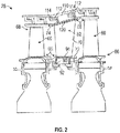
- FIG. 2 is a schematic view of a portion of the turbine section 28 that may employ various embodiments disclosed herein.
- Turbine section 28 includes a plurality of airfoils including, for example, at least one blade 60 and at least one vane 62.
- the blade 60 or the vane 62 may be a hollow body with internal cavities defining a number of channels or cores, hereinafter airfoil cores, formed therein and extending from an inner diameter 66 to an outer diameter 68, or vice versa.
- the airfoil cores may be separated by partitions within the blade 60 or the vane 62 that may extend between the inner diameter 66 and the outer diameter 68 of the blade 60 or the vane 62.
- the partitions may extend for a portion of the length of the blade 60 or the vane 62, but may stop or end prior to forming a complete wall within the blade 60 or the vane 62.
- each of the airfoil cores may be fluidly connected and form a fluid path within the blade 60 or the vane 62.
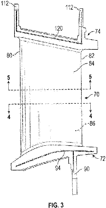
- the vane 62 may include an airfoil 70 radially extending between an inner platform 72 and an outer platform 74.
- the airfoil 70 provides a leading edge 80, a trailing edge 82 disposed opposite the leading edge 80, a pressure side 84 axially extending between the leading edge 80 and the trailing edge 82, and a suction side 86 disposed opposite the pressure side 84 and axially extending between the leading edge 80 and the trailing edge 82.
- a chord length 88 is defined between the leading edge 80 and the trailing edge 82.
- the inner platform 72 is located proximate the inner diameter 66.
- the inner platform 72 includes a radially inwardly extending tab 90.
- the radially inwardly extending tab 90 extends from the inner platform 72 and connects the vane 62 to an inner sealing member 92.
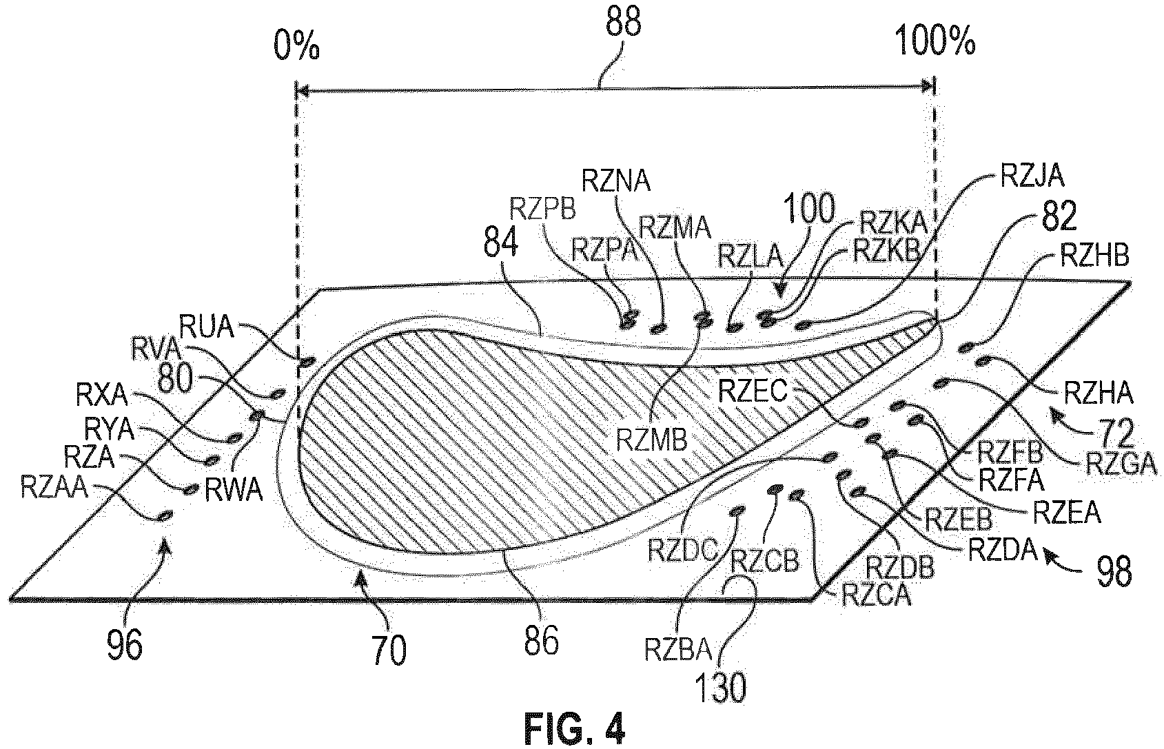
- the inner platform 72 defines an inner cooling passage 94, a plurality of first inner cooling holes 96, a plurality of second inner cooling holes 98, and a plurality of third inner cooling holes 100.
- the inner cooling passage 94 extends through the tab 90 and the body of the inner platform 72.
- the inner cooling passage 94 is fluidly connected to an airflow port and/or bleed orifice.
- the inner cooling passage 94 facilitates air to flow from a cooling air source and onto the inner platform 72 through the plurality of first inner cooling holes 96, the plurality of second inner cooling holes 98, and the plurality of third inner cooling holes 100.
- the plurality of inner cooling holes may have a cone shape a rounded shape, an elongated slot shape, as well as other shapes.
- the plurality of first inner cooling holes 96 are fluidly connected to the inner cooling passage 94.
- the plurality of first inner cooling holes 96 are disposed proximate the leading edge 80.
- the plurality of first inner cooling holes 96 extend circumferentially across the inner platform 72 from a point circumferentially spaced apart from the pressure side 84 and extend towards the suction side 86 of the airfoil 70.
- the plurality of first inner cooling holes 96 have a first diameter and a first density.
- the density of the plurality of first inner cooling holes 96 corresponds to a total number of cooling holes within a given area.
- the plurality of first inner cooling holes 96 extends generally in a row.
- the row of the plurality of first inner cooling holes 96 includes cooling holes RUA, RVA, RWA, RXA, RYA, RZA, and RZAA
- the plurality of second inner cooling holes 98 are fluidly connected to the inner cooling passage 94.
- the plurality of second inner cooling holes 98 are spaced apart from the plurality of first inner cooling holes 96.
- the plurality of second inner cooling holes 98 are disposed proximate the trailing edge 82 and the suction side 86.
- the plurality of second inner cooling holes 98 extend from the trailing edge 82 towards the leading edge 80.
- the plurality of second inner cooling holes 98 extend between 60% and 100% of the chord length 88.
- the plurality of second inner cooling holes 98 have a second diameter and a second density.
- the second diameter of the plurality of second inner cooling holes 98 is greater than the first diameter of the plurality of first inner cooling holes 96.
- the second density of the plurality of second inner cooling holes 98 is greater than the first density of the plurality of first inner cooling holes 96.
- the larger diameter and greater density of the plurality of second inner cooling holes 98 facilitates improved or greater cooling of the inner platform 72 to reduce material temperature at the inner platform 72 and therefore mitigate the potential of oxidation on the inner platform 72.
- the plurality of second inner cooling holes 98 includes cooling holes RZBA, RZCB, RZCA, RZDA, RZDB, RZDC, RZEA, RZEB, RZEC, RZFA, RZFB, RZGA, RZHA, and RZHB.
- the plurality of third inner cooling holes 100 are fluidly connected to the inner cooling passage 94.
- the plurality of third inner cooling holes 100 are spaced apart from the plurality of first inner cooling holes 96 and the plurality of second inner cooling holes 98.
- the plurality of third inner cooling holes 100 are disposed proximate the trailing edge 82 and the pressure side 84.
- the plurality of third inner cooling holes 100 extend from the trailing edge 82 towards the leading edge 80.
- the plurality of third inner cooling holes 100 extend between 50% and 100% of the chord length 88.
- the plurality of third inner cooling holes 100 have a third diameter and a third density.
- the third diameter of the plurality of third inner cooling holes 100 is greater than the first diameter of the plurality of the first inner cooling holes 96.
- the third density of the plurality of third inner cooling holes 100 is greater than the first density of the plurality of first inner cooling holes 96.
- the third diameter is equal to the second diameter and the third density is equal to the second density.
- the larger diameter and greater density of the plurality of third inner cooling holes 100 facilitates improved cooling of the inner platform 72 to reduce material temperature at the inner platform 72 and therefore mitigate the potential of oxidation on the inner platform 72.
- the plurality of third inner cooling holes 100 includes cooling holes RZJA, RZKA, RZKB, RZLA, RZMA, RZMB, RZNA, RZPA, and RZPB.
- Table 1 identifies each cooling hole of the plurality of first inner cooling holes 96, the plurality of second inner cooling holes 98, and the plurality of third inner cooling holes 100 that are disposed or formed on the inner platform 72.
- the three or four-letter identifier denotes the row (the first two letters) and the column (the third letter or the third and fourth letters).
- the number denotes the hole numbers of the cooling hole.
- the geometric coordinates, Xi, Yi, Zi, represent an approximate true position of a nominal part of a centre point of the cooling hole.
- the geometric coordinates are in accordance with or in substantial conformance with a Cartesian coordinate system that has orthogonally related X, Y, and Z axes.
- the X axis is defined along the direction of the engine centreline longitudinal axis A
- the Y axis is defined in a substantially circumferential or rotational direction about the engine centreline longitudinal axis A
- the Z axis is defined in a radial direction that is substantially perpendicular to the engine centreline longitudinal axis A.
- Each of the geometric coordinates is measured from a reference point located at an intersection of at least one casting datum and the engine centreline longitudinal axis A.
- the Cartesian coordinate values are expressed in inches to a centre point of each cooling holes.
- the cooling holes have a diametrical surface tolerance relative to the specified coordinates of 0.022 inches (0.558 mm) or 0.017 inches (0.431 mm). In other words, due to manufacturing tolerances, the external breakout of the centreline of each cooling hole may fall within a 0.022 inch diameter circle or a 0.017 inch diameter circle inscribed on the surface of the inner platform 72.
- the outer platform 74 is located proximate the outer diameter 68.
- the outer platform 74 is disposed proximate a case 110 that is disposed about the turbine section 28.
- the outer platform 74 is arranged to operatively connect the vane 62 to the case 110.
- the outer platform 74 includes a vane hook 112 that extends from the outer platform 74 towards the case 110.
- the vane hook 112 engages a case hook 114 that extends from the case 110 towards the outer platform 74.
- the vane hook 112 engages the case hook 114 to secure the vane 62 to the case 110.
- the outer platform 74 defines an outer cooling passage 120, a plurality of first outer cooling holes 122, a plurality of second outer cooling holes 124, and a plurality of third outer cooling holes 126.
- the outer cooling passage 120 extends through the vane hook 112 and the body of the outer platform 74.
- the outer cooling passage 120 is fluidly connected to an airflow ports and/or a bleed orifice.
- the outer cooling passage hundred and 20 facilitates air to flow from a cooling air source and onto the outer platform 74 through the plurality of first outer cooling holes 122, the plurality of second outer cooling holes 124, and the plurality of third outer cooling holes 126.
- the plurality of outer cooling holes may have a cone shape, a rounded shape, an elongated slot shape, as well as other shapes.
- the plurality of first outer cooling holes 122 are fluidly connected to the outer cooling passage 120.
- the plurality of first outer cooling holes 122 are disposed proximate the leading edge 80.
- the plurality of first outer cooling holes 122 and are spaced apart from the pressure side 84 and the suction side 86.
- the plurality of first outer cooling holes 122 has a first diameter that is equal to the first diameter of the plurality of first inner cooling holes 96.
- the plurality of first outer cooling holes 122 have a first density that is equal to the first density of the plurality of first inner cooling holes 96.
- the plurality of first outer cooling holes 122 includes cooling holes TAA, TAB, TAC, and TAD.
- the plurality of second outer cooling holes 124 are fluidly connected to the outer cooling passage 120.
- the plurality of second outer cooling holes 124 are spaced apart from the plurality of first outer cooling holes 122.
- the plurality of second outer cooling holes 124 are disposed proximate the trailing edge 82 and the suction side 86.
- the plurality of second outer cooling holes 124 extend from the trailing edge 82 towards the leading edge 80.
- the plurality of second outer cooling holes 124 is spaced apart from the trailing edge 82.
- the plurality of second outer cooling holes 124 extend between 50% and 90% of the chord length 88.
- the plurality of second outer cooling holes 124 have a second diameter and a second density.
- the second diameter of the plurality of second outer cooling holes 124 is greater than the diameter of the plurality of first outer cooling holes 122.
- the second density of the plurality of second outer cooling holes 124 is greater than the density of the plurality of first outer cooling holes 122.
- the larger diameter and greater density of the plurality of second outer cooling holes 124 facilitates improved cooling of the outer platform 74 to reduce material temperature at the outer platform 74 and therefore mitigates the potential of oxidation on the outer platform 74.
- the plurality of second outer cooling holes 124 includes cooling holes TBB, TBA, TCB, TCA, TDC, TDB, TDA, TEA, TEB, TEC, TED, TEE, TEF, TFA, TFB, TFC, TFD, TKA, TLA, TMA, and TNA.
- the plurality of third outer cooling holes 126 are fluidly connected to the outer cooling passage 120.
- the plurality of third outer cooling holes 126 are spaced apart from the plurality of first outer cooling holes 122 and the plurality of second outer cooling holes 124.
- the plurality of third outer cooling holes 126 are disposed proximate the pressure side 84.
- the plurality of third outer cooling holes 126 extend between the leading edge 80 and the trailing edge 82.
- the plurality of third outer cooling holes 126 extend beyond the trailing edge 82 and wrap around and extend towards the suction side 86.
- the plurality of third outer cooling holes 126 extend between 0% and 100% of the chord length 88. In at least one embodiment, the plurality of third outer cooling holes 126 extends between 15% and 90% of the chord length 88.
- the plurality of third outer cooling holes 126 have a third diameter and a third density.
- the third diameter of the plurality of third outer cooling holes 126 is substantially similar to the diameter of the plurality of first outer cooling holes 122.
- the third density of the plurality of third outer cooling holes 126 is substantially similar to the density of the plurality of first outer cooling holes 122.
- Table 2 identifies each cooling hole of the plurality of first outer cooling holes 122, the plurality of second outer cooling holes 124, and the plurality of third outer cooling holes 126 that are disposed or formed on the outer platform 74.
- the three-letter identifier denotes the row (the first two letters) and the column (the third letter).
- the number denotes the hole number of the cooling hole.
- the geometric coordinates, Xo, Yo, Zo, represent an approximate true position of a nominal part of a centre point of the cooling hole.
- the geometric coordinates are in accordance with or in substantial conformance with a Cartesian coordinate system that has orthogonally related X, Y, and Z axes.
- the X axis is defined along the direction of the engine centreline longitudinal axis A
- the Y axis is defined in a substantially circumferential or rotational direction about the engine centreline longitudinal axis A
- the Z axis is defined in a radial direction that is substantially perpendicular to the engine centreline longitudinal axis A.
- Each of the geometric coordinates is measured from the reference point located at the intersection of at least one casting datum and the engine centreline longitudinal axis A.
- the reference point for the locations of the plurality of outer cooling holes may be the same reference point for the locations of the plurality of inner cooling holes.
- the Cartesian coordinate values are expressed in inches. However, the values of Table 2 could be converted to millimetres by multiplying by 25.4, or could be converted to any other units.
- the cooling holes have a diametrical surface tolerance relative to the specified coordinates of 0.022 inches (0.558 mm) or 0.017 inches (0.431 mm). In other words, due to manufacturing tolerances, the external breakout of the centreline of each cooling hole may fall within a 0.022 inch diameter circle or a 0.017 inch diameter circle inscribed on the surface of the outer platform 74.
- a thermal barrier coating 130 may be applied to at least one of the inner platform 72 and the outer platform 74.
- the thermal barrier coating 130 may be applied to the platforms after the forming or drilling of the plurality of cooling holes.
Landscapes
- Engineering & Computer Science (AREA)
- Mechanical Engineering (AREA)
- General Engineering & Computer Science (AREA)
- Physics & Mathematics (AREA)
- Fluid Mechanics (AREA)
- Turbine Rotor Nozzle Sealing (AREA)
Abstract
Description
- Gas turbine engines are provided with turbine vanes that extend into a core flow path of the gas turbine engine. The turbine vanes generally do not rotate but guide airflow. The turbine vane is provided with cooling features to protect the turbine vane from the hot combustion gases. Some of the cooling features of the turbine vane may be subject to oxidation. Accordingly it is desirable to provide a turbine vane having cooling features that reduce turbine vane operating temperatures as well as mitigate oxidation.
- According to an embodiment of the present disclosure, a turbine vane for a gas turbine engine is provided. The turbine vane includes an inner platform and an outer platform joined together by an airfoil. The airfoil has a leading edge and a trailing edge joined together by a pressure side and a suction side disposed opposite the pressure side. The inner platform defines a plurality of inner cooling holes at geometric coordinates in substantial conformance with Cartesian coordinate values of Xi, Yi, and Zi as set forth in Table 1, wherein each of the geometric coordinates is measured from an engine centreline, and the Cartesian coordinate values of Table 1 are expressed in inches. The cooling holes have a diametrical surface tolerance relative to the specified coordinates of at least one of 0.022 inches (0.558 mm) and 0.017 inches (0.431 mm).
- In addition to one or more of the features described above, or as an alternative to any of the foregoing embodiments, the plurality of inner cooling holes includes a plurality of first inner cooling holes and a plurality of second inner cooling holes that are fluidly connected to an inner cooling passage, the plurality of first inner cooling holes being disposed proximate the leading edge and extending towards the suction side and the plurality of second inner cooling holes being disposed proximate the trailing edge and the suction side and extending towards the leading edge.
- In addition to one or more of the features described above, or as an alternative to any of the foregoing embodiments, the plurality of inner cooling holes further includes a plurality of third inner cooling holes that are fluidly connected to the inner cooling passage and are disposed proximate the trailing edge and the pressure side and extend towards the leading edge.
- In addition to one or more of the features described above, or as an alternative to any of the foregoing embodiments, the plurality of first inner cooling holes has a first diameter and the plurality of second inner cooling holes has a second diameter that is less than the first diameter.
- In addition to one or more of the features described above, or as an alternative to any of the foregoing embodiments, the outer platform defines a plurality of outer cooling holes at geometric coordinates substantial conformance with Cartesian coordinate values of Xo, Yo, Zo as set forth in Table 2, wherein each of the geometric coordinates is measured from the engine centreline, and the Cartesian coordinate values of Table 2 are expressed in inches. The cooling holes have a diametrical surface tolerance relative to the specified coordinates of at least one of 0.022 inches (0.558 mm) and 0.017 inches (0.431 mm).
- In addition to one or more of the features described above, or as an alternative to any of the foregoing embodiments, wherein the plurality of outer cooling holes includes a plurality of first outer cooling holes and a plurality of second outer cooling holes that are fluidly connected to an outer cooling passage, the plurality of first outer cooling holes being disposed proximate the leading edge, and the plurality of second outer cooling holes being disposed proximate the trailing edge and the suction side extending towards the leading edge.
- In addition to one or more of the features described above, or as an alternative to any of the foregoing embodiments, the plurality of outer cooling holes further includes a plurality of third outer cooling holes that are fluidly connected to the outer cooling passage, the plurality of third outer cooling holes are disposed proximate the pressure side and extend between the leading edge and the trailing edge.
- In addition to one or more of the features described above, or as an alternative to any of the foregoing embodiments, a portion of the plurality of third outer cooling holes extend beyond the trailing edge and extend towards the suction side.
- In addition to one or more of the features described above, or as an alternative to any of the foregoing embodiments, the plurality of first outer cooling holes has a first diameter and the plurality of second outer cooling holes has a second diameter that is less than the first diameter.
- According to another embodiment of the present disclosure, a turbine vane for a gas turbine engine is provided. The turbine vane includes an inner platform, an outer platform, and an airfoil. The outer platform defines a plurality of outer cooling holes at geometric coordinates in substantial conformance with Cartesian coordinate values of Xo, Yo, Zo as set forth in Table 2, wherein each of the geometric coordinates is measured from an engine longitudinal axis, and the Cartesian coordinate values of Table 2 are expressed in inches. The airfoil has a chord length that is defined between a leading edge and a trailing edge. The airfoil joins the inner platform to the outer platform. The cooling holes have a diametrical surface tolerance relative to the specified coordinates of at least one of 0.022 inches (0.558 mm) and 0.017 inches (0.431 mm).
- In addition to one or more of the features described above, or as an alternative to any of the foregoing embodiments, the inner platform defines a plurality of inner cooling holes at geometric coordinates in substantial conformance with Cartesian coordinate values of Xi, Yi, and Zi as set forth in Table 1, wherein each of the geometric coordinates is measured from the engine longitudinal axis, and the Cartesian coordinate values of Table 1 are expressed in inches. The cooling holes have a diametrical surface tolerance relative to the specified coordinates of at least one of 0.022 inches (0.558 mm) and 0.017 inches (0.431 mm).
- In addition to one or more of the features described above, or as an alternative to any of the foregoing embodiments, the plurality of inner cooling holes includes a plurality of first inner cooling holes that extend circumferentially across the inner platform and are disposed proximate the leading edge.
- In addition to one or more of the features described above, or as an alternative to any of the foregoing embodiments, the plurality of second inner cooling holes extend between 60% and 100% of the chord length.
- In addition to one or more of the features described above, or as an alternative to any of the foregoing embodiments, the plurality of third inner cooling holes extend between 50% and 100% of the chord length.
- In addition to one or more of the features described above, or as an alternative to any of the foregoing embodiments, the plurality of outer cooling holes includes a plurality of first outer cooling holes that extend circumferentially across the inner platform and are disposed proximate the leading edge.
- In addition to one or more of the features described above, or as an alternative to any of the foregoing embodiments, the plurality of second outer cooling holes extend between 50% and 100% of the chord length.
- In addition to one or more of the features described above, or as an alternative to any of the foregoing embodiments, the plurality of outer cooling holes includes a plurality of third outer cooling holes that extend between 0% and 100% of the chord length.
- According to yet another embodiment of the present disclosure, a gas turbine engine is provided. The gas turbine engine includes a turbine section that is disposed adjacent to a combustor section. The turbine section includes a turbine vane having an inner platform and an outer platform joined together by an airfoil having a pressure side and a suction side each extending between a leading edge and a trailing edge. The inner platform defines a plurality of first inner cooling holes disposed proximate the leading edge and extend towards the suction side, a plurality of second inner cooling holes disposed proximate the trailing edge and the suction side, and a plurality of third inner cooling holes disposed proximate the trailing edge and the pressure side.
- In addition to one or more of the features described above, or as an alternative to any of the foregoing embodiments, the outer platform defines a plurality of first outer cooling holes disposed proximate the leading edge, a plurality of second outer cooling holes disposed proximate the trailing edge and the suction side, and a plurality of third outer cooling holes disposed proximate the suction side and wrap around the trailing edge and extends towards the suction side.
- In addition to one or more of the features described above, or as an alternative to any of the foregoing embodiments, the plurality of first outer cooling holes has a first diameter and the plurality of second outer cooling holes has a second diameter that is less than the first diameter.
- The following descriptions should not be considered limiting in any way. With reference to the accompanying drawings, like elements are numbered alike:
-
FIG. 1 is a schematic illustration of a gas turbine engine; -
FIG. 2 is a cross-sectional view of a portion of the gas turbine engine; -
FIG. 3 is a perspective view of a turbine vane; -
FIG. 4 is an elevation view of an inner platform of the turbine vane along section line 4-4; and -
FIG. 5 is an elevation view of an outer platform of the turbine vane along section line 5-5. - A detailed description of one or more embodiments of the disclosed apparatus and method are presented herein by way of exemplification and not limitation with reference to the Figures.
-
FIG. 1 schematically illustrates agas turbine engine 20. Thegas turbine engine 20 is disclosed herein as a two-spool turbofan that generally incorporates afan section 22, acompressor section 24, acombustor section 26 and aturbine section 28. Alternative engines might include an augmentor section (not shown) among other systems or features. Thefan section 22 drives air along a bypass flow path B in a bypass duct, while thecompressor section 24 drives air along a core flow path C for compression and communication into thecombustor section 26 then expansion through theturbine section 28. Although depicted as a two-spool turbofan gas turbine engine in the disclosed non-limiting embodiment, it should be understood that the concepts described herein are not limited to use with two-spool turbofans as the teachings may be applied to other types of turbine engines including three-spool architectures. - The
gas turbine engine 20 generally includes alow speed spool 30 and ahigh speed spool 32 mounted for rotation about an engine central longitudinal axis A relative to an enginestatic structure 36 viaseveral bearing systems 38. It should be understood thatvarious bearing systems 38 at various locations may alternatively or additionally be provided and the location ofbearing systems 38 may be varied as appropriate to the application. - The
low speed spool 30 generally includes aninner shaft 40 that interconnects afan 42, alow pressure compressor 44 and alow pressure turbine 46. Theinner shaft 40 is connected to thefan 42 through a speed change mechanism, which ingas turbine engine 20 is illustrated as a gearedarchitecture 48 to drive thefan 42 at a lower speed than thelow speed spool 30. Thehigh speed spool 32 includes anouter shaft 50 that interconnects ahigh pressure compressor 52 andhigh pressure turbine 54. - A
combustor 56 of thecombustor section 26 is arranged in thegas turbine engine 20. Thecombustor 56 is arranged between thehigh pressure compressor 52 and thehigh pressure turbine 54. An enginestatic structure 36 is arranged generally between thehigh pressure turbine 54 and thelow pressure turbine 46. The enginestatic structure 36 further supports bearingsystems 38 in theturbine section 28. - The
inner shaft 40 and theouter shaft 50 are concentric and rotate via bearingsystems 38 about the engine central longitudinal axis A which is collinear with their longitudinal axes. - The core airflow is compressed by the
low pressure compressor 44 then thehigh pressure compressor 52, mixed and burned with fuel in thecombustor 56, then expanded over thehigh pressure turbine 54 andlow pressure turbine 46. Theturbines low speed spool 30 andhigh speed spool 32 in response to the expansion. It will be appreciated that each of the positions of thefan section 22,compressor section 24,combustor section 26,turbine section 28, and fandrive gear system 48 may be varied. For example,gear system 48 may be located aft ofcombustor section 26 or even aft ofturbine section 28, andfan section 22 may be positioned forward or aft of the location ofgear system 48. - Although the
gas turbine engine 20 is depicted as a turbofan, it should be understood that the concepts described herein are not limited to use with the described configuration, as the teachings may be applied to other types of engines such as, but not limited to, turbojets, turboshafts, and three-spool (plus fan) turbofans wherein an intermediate spool includes an intermediate pressure compressor ("IPC") between a low pressure compressor ("LPC") and a high pressure compressor ("HPC"), and an intermediate pressure turbine ("IPT") between the high pressure turbine ("HPT") and the low pressure turbine ("LPT"). -
FIG. 2 is a schematic view of a portion of theturbine section 28 that may employ various embodiments disclosed herein.Turbine section 28 includes a plurality of airfoils including, for example, at least oneblade 60 and at least one vane 62. Theblade 60 or the vane 62 may be a hollow body with internal cavities defining a number of channels or cores, hereinafter airfoil cores, formed therein and extending from aninner diameter 66 to anouter diameter 68, or vice versa. The airfoil cores may be separated by partitions within theblade 60 or the vane 62 that may extend between theinner diameter 66 and theouter diameter 68 of theblade 60 or the vane 62. The partitions may extend for a portion of the length of theblade 60 or the vane 62, but may stop or end prior to forming a complete wall within theblade 60 or the vane 62. Thus, each of the airfoil cores may be fluidly connected and form a fluid path within theblade 60 or the vane 62. - Referring to
FIGS. 2 to 5 , the vane 62 may include anairfoil 70 radially extending between aninner platform 72 and anouter platform 74. Theairfoil 70 provides aleading edge 80, a trailingedge 82 disposed opposite the leadingedge 80, apressure side 84 axially extending between theleading edge 80 and the trailingedge 82, and asuction side 86 disposed opposite thepressure side 84 and axially extending between theleading edge 80 and the trailingedge 82. Achord length 88 is defined between theleading edge 80 and the trailingedge 82. - The
inner platform 72 is located proximate theinner diameter 66. Theinner platform 72 includes a radially inwardly extendingtab 90. The radially inwardly extendingtab 90 extends from theinner platform 72 and connects the vane 62 to aninner sealing member 92. - The
inner platform 72 defines aninner cooling passage 94, a plurality of first inner cooling holes 96, a plurality of second inner cooling holes 98, and a plurality of third inner cooling holes 100. Theinner cooling passage 94 extends through thetab 90 and the body of theinner platform 72. Theinner cooling passage 94 is fluidly connected to an airflow port and/or bleed orifice. Theinner cooling passage 94 facilitates air to flow from a cooling air source and onto theinner platform 72 through the plurality of first inner cooling holes 96, the plurality of second inner cooling holes 98, and the plurality of third inner cooling holes 100. The plurality of inner cooling holes may have a cone shape a rounded shape, an elongated slot shape, as well as other shapes. - Referring to
FIG. 4 , the plurality of first inner cooling holes 96 are fluidly connected to theinner cooling passage 94. The plurality of first inner cooling holes 96 are disposed proximate theleading edge 80. The plurality of first inner cooling holes 96 extend circumferentially across theinner platform 72 from a point circumferentially spaced apart from thepressure side 84 and extend towards thesuction side 86 of theairfoil 70. - The plurality of first inner cooling holes 96 have a first diameter and a first density. The density of the plurality of first inner cooling holes 96 corresponds to a total number of cooling holes within a given area.
- The plurality of first inner cooling holes 96 extends generally in a row. The row of the plurality of first inner cooling holes 96 includes cooling holes RUA, RVA, RWA, RXA, RYA, RZA, and RZAA
- The plurality of second inner cooling holes 98 are fluidly connected to the
inner cooling passage 94. The plurality of second inner cooling holes 98 are spaced apart from the plurality of first inner cooling holes 96. The plurality of second inner cooling holes 98 are disposed proximate the trailingedge 82 and thesuction side 86. The plurality of second inner cooling holes 98 extend from the trailingedge 82 towards the leadingedge 80. The plurality of second inner cooling holes 98 extend between 60% and 100% of thechord length 88. - The plurality of second inner cooling holes 98 have a second diameter and a second density. The second diameter of the plurality of second inner cooling holes 98 is greater than the first diameter of the plurality of first inner cooling holes 96. The second density of the plurality of second inner cooling holes 98 is greater than the first density of the plurality of first inner cooling holes 96. The larger diameter and greater density of the plurality of second inner cooling holes 98 facilitates improved or greater cooling of the
inner platform 72 to reduce material temperature at theinner platform 72 and therefore mitigate the potential of oxidation on theinner platform 72. - The plurality of second inner cooling holes 98 includes cooling holes RZBA, RZCB, RZCA, RZDA, RZDB, RZDC, RZEA, RZEB, RZEC, RZFA, RZFB, RZGA, RZHA, and RZHB.
- The plurality of third inner cooling holes 100 are fluidly connected to the
inner cooling passage 94. The plurality of third inner cooling holes 100 are spaced apart from the plurality of first inner cooling holes 96 and the plurality of second inner cooling holes 98. The plurality of third inner cooling holes 100 are disposed proximate the trailingedge 82 and thepressure side 84. The plurality of third inner cooling holes 100 extend from the trailingedge 82 towards the leadingedge 80. The plurality of third inner cooling holes 100 extend between 50% and 100% of thechord length 88. - The plurality of third inner cooling holes 100 have a third diameter and a third density. The third diameter of the plurality of third inner cooling holes 100 is greater than the first diameter of the plurality of the first inner cooling holes 96. The third density of the plurality of third inner cooling holes 100 is greater than the first density of the plurality of first inner cooling holes 96. In at least one embodiment the third diameter is equal to the second diameter and the third density is equal to the second density. The larger diameter and greater density of the plurality of third inner cooling holes 100 facilitates improved cooling of the
inner platform 72 to reduce material temperature at theinner platform 72 and therefore mitigate the potential of oxidation on theinner platform 72. - The plurality of third inner cooling holes 100 includes cooling holes RZJA, RZKA, RZKB, RZLA, RZMA, RZMB, RZNA, RZPA, and RZPB.
- Table 1 identifies each cooling hole of the plurality of first inner cooling holes 96, the plurality of second inner cooling holes 98, and the plurality of third inner cooling holes 100 that are disposed or formed on the
inner platform 72. The three or four-letter identifier denotes the row (the first two letters) and the column (the third letter or the third and fourth letters). The number denotes the hole numbers of the cooling hole. The geometric coordinates, Xi, Yi, Zi, represent an approximate true position of a nominal part of a centre point of the cooling hole. - The geometric coordinates are in accordance with or in substantial conformance with a Cartesian coordinate system that has orthogonally related X, Y, and Z axes. The X axis is defined along the direction of the engine centreline longitudinal axis A, the Y axis is defined in a substantially circumferential or rotational direction about the engine centreline longitudinal axis A, and the Z axis is defined in a radial direction that is substantially perpendicular to the engine centreline longitudinal axis A. Each of the geometric coordinates is measured from a reference point located at an intersection of at least one casting datum and the engine centreline longitudinal axis A. The Cartesian coordinate values are expressed in inches to a centre point of each cooling holes. However, the values of Table 1 could be converted to millimetres by multiplying by 25.4, or could be converted to any other units. The cooling holes have a diametrical surface tolerance relative to the specified coordinates of 0.022 inches (0.558 mm) or 0.017 inches (0.431 mm). In other words, due to manufacturing tolerances, the external breakout of the centreline of each cooling hole may fall within a 0.022 inch diameter circle or a 0.017 inch diameter circle inscribed on the surface of the
inner platform 72.TABLE 1 HOLE # Xi Yi Zi RAA 1 -0.854 1.801 14.464 RBA 2 -0.577 1.525 14.695 RCA 3 -0.368 1.316 14.822 RDA 4 -0.155 1.103 14.907 REA 5 1.307 -0.639 14.898 RFA 6 1.307 -0.859 14.886 RGA 7 1.307 -1.079 14.872 RHA 8 1.307 -1.299 14.854 RJA 9 1.307 -1.519 14.833 RKA 10 1.307 -1.739 14.809 RLA 11 1.307 -1.959 14.782 RMA 12 0.388 -1.378 14.904 RNA 13 0.165 -1.157 14.940 RPA 14 -0.054 -0.937 14.939 RRA 15 -0.268 -0.716 14.906 RSA 16 -0.479 -0.495 14.839 RTA 17 -0.685 -0.274 14.737 RUA 18 -0.915 0.449 14.665 RVA 19 -0.907 0.621 14.664 RWA 20 -0.905 0.771 14.658 RXA 21 -0.899 0.903 14.655 RYA 22 -0.898 1.034 14.647 RZA 23 -0.887 1.182 14.644 RZAA 24 -0.890 1.337 14.628 RZBA 25 0.830 -0.473 15.006 RZCA 26 0.963 -0.672 14.988 RZCB 27 0.884 -0.626 14.996 RZDA 28 1.138 -0.866 14.965 RZDB 29 1.036 -0.866 14.973 RZDC 30 0.941 -0.877 14.979 RZEA 31 1.109 -1.061 14.954 RZEB 32 1.012 -1.062 14.962 RZEC 33 0.935 -1.091 14.965 RZFA 34 1.083 -1.255 14.941 RZFB 35 0.993 -1.256 14.948 RZGA 36 1.051 -1.450 14.926 RZHA 37 1.109 -1.643 14.902 RZHB 38 1.024 -1.631 14.910 RZJA 39 0.482 -1.202 14.991 RZKA 40 0.327 -1.104 15.010 RZKB 41 0.355 -1.073 15.010 RZLA 42 0.279 -0.977 15.023 RZMA 43 0.156 -0.917 15.033 RZMB 44 0.185 -0.887 15.034 RZNA 45 0.063 -0.743 15.041 RZPA 46 -0.079 -0.683 15.031 RZPB 47 -0.051 -0.654 15.036 - Referring to
FIGS. 2 to 5 , theouter platform 74 is located proximate theouter diameter 68. Theouter platform 74 is disposed proximate acase 110 that is disposed about theturbine section 28. Theouter platform 74 is arranged to operatively connect the vane 62 to thecase 110. Theouter platform 74 includes avane hook 112 that extends from theouter platform 74 towards thecase 110. Thevane hook 112 engages acase hook 114 that extends from thecase 110 towards theouter platform 74. Thevane hook 112 engages thecase hook 114 to secure the vane 62 to thecase 110. - The
outer platform 74 defines anouter cooling passage 120, a plurality of first outer cooling holes 122, a plurality of second outer cooling holes 124, and a plurality of third outer cooling holes 126. Theouter cooling passage 120 extends through thevane hook 112 and the body of theouter platform 74. Theouter cooling passage 120 is fluidly connected to an airflow ports and/or a bleed orifice. The outer cooling passage hundred and 20 facilitates air to flow from a cooling air source and onto theouter platform 74 through the plurality of first outer cooling holes 122, the plurality of second outer cooling holes 124, and the plurality of third outer cooling holes 126. The plurality of outer cooling holes may have a cone shape, a rounded shape, an elongated slot shape, as well as other shapes. - Referring to
FIG. 5 , the plurality of first outer cooling holes 122 are fluidly connected to theouter cooling passage 120. The plurality of first outer cooling holes 122 are disposed proximate theleading edge 80. The plurality of first outer cooling holes 122 and are spaced apart from thepressure side 84 and thesuction side 86. - The plurality of first outer cooling holes 122 has a first diameter that is equal to the first diameter of the plurality of first inner cooling holes 96. The plurality of first outer cooling holes 122 have a first density that is equal to the first density of the plurality of first inner cooling holes 96.
- The plurality of first outer cooling holes 122 includes cooling holes TAA, TAB, TAC, and TAD.
- The plurality of second outer cooling holes 124 are fluidly connected to the
outer cooling passage 120. The plurality of second outer cooling holes 124 are spaced apart from the plurality of first outer cooling holes 122. The plurality of second outer cooling holes 124 are disposed proximate the trailingedge 82 and thesuction side 86. The plurality of second outer cooling holes 124 extend from the trailingedge 82 towards the leadingedge 80. In at least one embodiment, the plurality of second outer cooling holes 124 is spaced apart from the trailingedge 82. The plurality of second outer cooling holes 124 extend between 50% and 90% of thechord length 88. - The plurality of second outer cooling holes 124 have a second diameter and a second density. The second diameter of the plurality of second outer cooling holes 124 is greater than the diameter of the plurality of first outer cooling holes 122. The second density of the plurality of second outer cooling holes 124 is greater than the density of the plurality of first outer cooling holes 122. The larger diameter and greater density of the plurality of second outer cooling holes 124 facilitates improved cooling of the
outer platform 74 to reduce material temperature at theouter platform 74 and therefore mitigates the potential of oxidation on theouter platform 74. - The plurality of second outer cooling holes 124 includes cooling holes TBB, TBA, TCB, TCA, TDC, TDB, TDA, TEA, TEB, TEC, TED, TEE, TEF, TFA, TFB, TFC, TFD, TKA, TLA, TMA, and TNA.
- The plurality of third outer cooling holes 126 are fluidly connected to the
outer cooling passage 120. The plurality of third outer cooling holes 126 are spaced apart from the plurality of first outer cooling holes 122 and the plurality of second outer cooling holes 124. The plurality of third outer cooling holes 126 are disposed proximate thepressure side 84. The plurality of third outer cooling holes 126 extend between theleading edge 80 and the trailingedge 82. The plurality of third outer cooling holes 126 extend beyond the trailingedge 82 and wrap around and extend towards thesuction side 86. The plurality of third outer cooling holes 126 extend between 0% and 100% of thechord length 88. In at least one embodiment, the plurality of third outer cooling holes 126 extends between 15% and 90% of thechord length 88. - The plurality of third outer cooling holes 126 have a third diameter and a third density. The third diameter of the plurality of third outer cooling holes 126 is substantially similar to the diameter of the plurality of first outer cooling holes 122. The third density of the plurality of third outer cooling holes 126 is substantially similar to the density of the plurality of first outer cooling holes 122.
- Table 2 identifies each cooling hole of the plurality of first outer cooling holes 122, the plurality of second outer cooling holes 124, and the plurality of third outer cooling holes 126 that are disposed or formed on the
outer platform 74. The three-letter identifier denotes the row (the first two letters) and the column (the third letter). The number denotes the hole number of the cooling hole. The geometric coordinates, Xo, Yo, Zo, represent an approximate true position of a nominal part of a centre point of the cooling hole. - The geometric coordinates are in accordance with or in substantial conformance with a Cartesian coordinate system that has orthogonally related X, Y, and Z axes. The X axis is defined along the direction of the engine centreline longitudinal axis A, the Y axis is defined in a substantially circumferential or rotational direction about the engine centreline longitudinal axis A, and the Z axis is defined in a radial direction that is substantially perpendicular to the engine centreline longitudinal axis A. Each of the geometric coordinates is measured from the reference point located at the intersection of at least one casting datum and the engine centreline longitudinal axis A. The reference point for the locations of the plurality of outer cooling holes may be the same reference point for the locations of the plurality of inner cooling holes. The Cartesian coordinate values are expressed in inches. However, the values of Table 2 could be converted to millimetres by multiplying by 25.4, or could be converted to any other units. The cooling holes have a diametrical surface tolerance relative to the specified coordinates of 0.022 inches (0.558 mm) or 0.017 inches (0.431 mm). In other words, due to manufacturing tolerances, the external breakout of the centreline of each cooling hole may fall within a 0.022 inch diameter circle or a 0.017 inch diameter circle inscribed on the surface of the
outer platform 74.TABLE 2 HOLE # Xo Yo Zo TAA 1 -0.585 1.216 18.020 TAB 2 -0.603 0.960 18.039 TAC 3 -0.469 1.116 18.000 TAD 4 -0.486 0.875 18.017 TBA 5 0.645 -0.262 17.783 TBB 6 0.552 -0.252 17.795 TCA 7 0.781 -0.440 17.750 TCB 8 0.676 -0.439 17.772 TDA 9 0.845 -0.629 17.736 TDB 10 0.764 -0.637 17.747 TDC 11 0.685 -0.650 17.754 TEA 12 1.093 -0.821 17.727 TEB 13 0.979 -0.821 17.727 TEC 14 0.862 -0.824 17.727 TED 15 1.225 -1.019 17.717 TEE 16 1.134 -1.017 17.717 TEF 17 1.043 -1.019 17.717 TFA 18 1.210 -1.185 17.706 TFB 19 1.154 -1.215 17.704 TFC 20 1.201 -1.344 17.695 TFD 21 1.161 -1.419 17.689 TKA 22 1.252 -2.003 17.632 TLA 23 1.126 -2.028 17.629 TMA 24 1.007 -2.068 17.624 TNA 25 0.895 -2.120 17.618 TPA 26 0.599 -1.768 17.707 TPB 27 0.425 -1.611 17.761 TPC 28 0.409 -1.408 17.782 TRA 29 0.257 -1.458 17.812 TRB 30 0.243 -1.275 17.829 TRC 31 0.082 -1.300 17.863 TRD 32 0.065 -1.086 17.882 TRE 33 -0.093 -1.142 17.914 TRF 34 -0.112 -0.898 17.932 TRG 35 -0.268 -0.984 17.962 TRH 36 -0.289 -0.712 17.980 TRJ 37 -0.443 -0.825 18.010 TRK 38 -0.454 -0.677 18.019 TRL 39 -0.466 -0.530 18.026 TRM 40 -0.618 -0.667 18.056 TRN 41 -0.630 -0.515 18.063 TRP 42 -0.641 -0.364 18.070 - A
thermal barrier coating 130 may be applied to at least one of theinner platform 72 and theouter platform 74. Thethermal barrier coating 130 may be applied to the platforms after the forming or drilling of the plurality of cooling holes. - The term "about" or "approximate" is intended to include the degree of error associated with measurement of the particular quantity based upon the equipment available at the time of filing the application. For example, "about" or "approximate" can include a range of ± 8% or 5%, or 2% of a given value.
- The terminology used herein is for the purpose of describing particular embodiments only and is not intended to be limiting of the present disclosure. As used herein, the singular forms "a", "an", and "the" are intended to include the plural forms as well, unless the context clearly indicates otherwise. It will be further understood that the terms "comprises" and/or "comprising", when used in this specification, specify the presence of stated features, integers, steps, operations, elements, and/or components, but do not preclude the presence or addition of one or more other features, integers, steps, operations, element components, and/or groups thereof.
- While the present disclosure has been described with reference to an exemplary embodiment or embodiments, it will be understood by those skilled in the art that various changes may be made and equivalents may be substituted for elements thereof without departing from the scope of the present disclosure. In addition, many modifications may be made to adapt a particular situation or material to the teachings of the present disclosure without departing from the essential scope thereof. Therefore, it is intended that the present disclosure not be limited to the particular embodiment disclosed as the best mode contemplated for carrying out this present disclosure, but that the present disclosure will include all embodiments falling within the scope of the claims.
Claims (15)
- A turbine vane for a gas turbine engine, comprising:an inner platform and an outer platform joined together by an airfoil, the airfoil including a leading edge and a trailing edge joined together by a pressure side and a suction side disposed opposite the pressure side,the inner platform defines a plurality of inner cooling holes at geometric coordinates in substantial conformance with Cartesian coordinate values of Xi, Yi, and Zi as set forth in Table 1, wherein each of the geometric coordinates is measured from an engine centreline, the Cartesian coordinate values of Table 1 are expressed in inches, the cooling holes have a diametrical surface tolerance relative to the coordinates of at least one of 0,022 inches (0.558 mm) and 0.017 inches (0.431 mm).
- The turbine vane of claim 1, wherein the plurality of inner cooling holes includes a plurality of first inner cooling holes and a plurality of second inner cooling holes that are fluidly connected to an inner cooling passage, the plurality of first inner cooling holes being disposed proximate the leading edge and extending towards the suction side and the plurality of second inner cooling holes being disposed proximate the trailing edge and the suction side and extending towards the leading edge.
- The turbine vane of claim 2, wherein the plurality of inner cooling holes further includes a plurality of third inner cooling holes that are fluidly connected to the inner cooling passage and are disposed proximate the trailing edge and the pressure side and extend towards the leading edge.
- The turbine vane of claim 2 or claim 3, wherein the plurality of first inner cooling holes has a first diameter and the plurality of second inner cooling holes has a second diameter that is less than the first diameter.
- The turbine vane of claim 1, wherein the outer platform defines a plurality of outer cooling holes at geometric coordinates in substantial conformance with Cartesian coordinate values of Xo, Yo, Zo as set forth in Table 2, wherein each of the geometric coordinates is measured from the engine centreline, the Cartesian coordinate values of Table 2 are expressed in inches, the cooling holes have a diametrical surface tolerance relative to the coordinates of at least one of 0.022 inches (0.558 mm) and 0.017 inches (0.431 mm).
- The turbine vane of claim 5, wherein the plurality of outer cooling holes includes a plurality of first outer cooling holes and a plurality of second outer cooling holes that are fluidly connected to an outer cooling passage, the plurality of first outer cooling holes being disposed proximate the leading edge, and the plurality of second outer cooling holes being disposed proximate the trailing edge and the suction side extending towards the leading edge.
- The turbine vane of claim 6, wherein the plurality of outer cooling holes further includes a plurality of third outer cooling holes that are fluidly connected to the outer cooling passage, the plurality of third outer cooling holes are disposed proximate the pressure side and extend between the leading edge and the trailing edge.
- The turbine vane of claim 7, wherein a portion of the plurality of third outer cooling holes extend beyond the trailing edge and extend towards the suction side.
- The turbine vane of claim 7 or claim 8, wherein the plurality of first outer cooling holes has a first diameter and the plurality of second outer cooling holes has a second diameter that is less than the first diameter.
- The turbine vane as in any one of claims 3 and 7, further comprising:an airfoil having a chord length defined between a leading edge and a trailing edge, the airfoil joining the inner platform to the outer platform.
- The turbine vane of claim 10, wherein the plurality of second inner cooling holes extend between 60% and 100% of the chord length.
- The turbine vane of claim 10 or claim 11, wherein the plurality of third inner cooling holes extend between 50% and 100% of the chord length.
- The turbine vane of any of claims 10 to 12, wherein the plurality of second outer cooling holes extend between 50% and 100% of the chord length.
- A gas turbine engine, comprising:a turbine section disposed adjacent to a combustor section, the turbine section comprising a turbine vane having an inner platform according to claim 1.
- The gas turbine engine of claim 14, wherein the turbine vane has an outer platform according to claim 5.
Priority Applications (1)
| Application Number | Priority Date | Filing Date | Title |
|---|---|---|---|
| EP19211067.4A EP3636882B1 (en) | 2016-12-12 | 2017-12-11 | Gas turbine engine |
Applications Claiming Priority (1)
| Application Number | Priority Date | Filing Date | Title |
|---|---|---|---|
| US15/375,827 US10428666B2 (en) | 2016-12-12 | 2016-12-12 | Turbine vane assembly |
Related Child Applications (2)
| Application Number | Title | Priority Date | Filing Date |
|---|---|---|---|
| EP19211067.4A Division EP3636882B1 (en) | 2016-12-12 | 2017-12-11 | Gas turbine engine |
| EP19211067.4A Division-Into EP3636882B1 (en) | 2016-12-12 | 2017-12-11 | Gas turbine engine |
Publications (2)
| Publication Number | Publication Date |
|---|---|
| EP3342986A1 true EP3342986A1 (en) | 2018-07-04 |
| EP3342986B1 EP3342986B1 (en) | 2024-06-19 |
Family
ID=60654827
Family Applications (2)
| Application Number | Title | Priority Date | Filing Date |
|---|---|---|---|
| EP17206360.4A Active EP3342986B1 (en) | 2016-12-12 | 2017-12-11 | Gas turbine engine |
| EP19211067.4A Active EP3636882B1 (en) | 2016-12-12 | 2017-12-11 | Gas turbine engine |
Family Applications After (1)
| Application Number | Title | Priority Date | Filing Date |
|---|---|---|---|
| EP19211067.4A Active EP3636882B1 (en) | 2016-12-12 | 2017-12-11 | Gas turbine engine |
Country Status (2)
| Country | Link |
|---|---|
| US (1) | US10428666B2 (en) |
| EP (2) | EP3342986B1 (en) |
Families Citing this family (5)
| Publication number | Priority date | Publication date | Assignee | Title |
|---|---|---|---|---|
| US10301966B2 (en) * | 2014-12-08 | 2019-05-28 | United Technologies Corporation | Turbine airfoil platform segment with film cooling hole arrangement |
| US10428666B2 (en) * | 2016-12-12 | 2019-10-01 | United Technologies Corporation | Turbine vane assembly |
| US11162369B1 (en) * | 2020-05-04 | 2021-11-02 | Raytheon Technologies Corporation | Turbine blade cooling hole combination |
| BE1031531B1 (en) * | 2023-04-21 | 2024-11-28 | Safran Aero Boosters | METHOD FOR SIZING TURBOMACHINE BLADED DISC STUMPS FOR ORBITAL WELDING |
| US12018587B1 (en) | 2023-10-04 | 2024-06-25 | Rtx Corporation | Turbine airfoil having cooling hole arrangement |
Citations (2)
| Publication number | Priority date | Publication date | Assignee | Title |
|---|---|---|---|---|
| WO2014007934A1 (en) * | 2012-07-02 | 2014-01-09 | United Technologies Corporation | Gas turbine engine turbine vane airfoil profile |
| WO2014035516A2 (en) * | 2012-07-02 | 2014-03-06 | United Technologies Corporation | Gas turbine engine turbine vane airfoil profile |
Family Cites Families (29)
| Publication number | Priority date | Publication date | Assignee | Title |
|---|---|---|---|---|
| US4863348A (en) * | 1987-02-06 | 1989-09-05 | Weinhold Wolfgang P | Blade, especially a rotor blade |
| US6478540B2 (en) * | 2000-12-19 | 2002-11-12 | General Electric Company | Bucket platform cooling scheme and related method |
| US6923623B2 (en) * | 2003-08-07 | 2005-08-02 | General Electric Company | Perimeter-cooled turbine bucket airfoil cooling hole location, style and configuration |
| US7373772B2 (en) * | 2004-03-17 | 2008-05-20 | General Electric Company | Turbine combustor transition piece having dilution holes |
| US7632072B2 (en) * | 2005-12-29 | 2009-12-15 | Rolls-Royce Power Engineering Plc | Third stage turbine airfoil |
| CA2634738C (en) * | 2005-12-29 | 2013-03-26 | Rolls-Royce Power Engineering Plc | Second stage turbine airfoil |
| US7806650B2 (en) * | 2006-08-29 | 2010-10-05 | General Electric Company | Method and apparatus for fabricating a nozzle segment for use with turbine engines |
| US8205458B2 (en) | 2007-12-31 | 2012-06-26 | General Electric Company | Duplex turbine nozzle |
| US8142137B2 (en) * | 2008-11-26 | 2012-03-27 | Alstom Technology Ltd | Cooled gas turbine vane assembly |
| US8944750B2 (en) * | 2011-12-22 | 2015-02-03 | Pratt & Whitney Canada Corp. | High pressure turbine vane cooling hole distribution |
| US9109453B2 (en) * | 2012-07-02 | 2015-08-18 | United Technologies Corporation | Airfoil cooling arrangement |
| US9322279B2 (en) * | 2012-07-02 | 2016-04-26 | United Technologies Corporation | Airfoil cooling arrangement |
| GB201219731D0 (en) * | 2012-11-02 | 2012-12-12 | Rolls Royce Plc | Gas turbine engine end-wall component |
| US9803488B2 (en) * | 2014-01-29 | 2017-10-31 | United Technologies Corporation | Turbine vane cooling arrangement |
| GB201413456D0 (en) * | 2014-07-30 | 2014-09-10 | Rolls Royce Plc | Gas turbine engine end-wall component |
| JP6312929B2 (en) | 2014-09-08 | 2018-04-18 | シーメンス エナジー インコーポレイテッド | In the platform, a cooled turbine vane platform having a front, a middle string and a rear cooling chamber |
| US10036259B2 (en) * | 2014-11-03 | 2018-07-31 | United Technologies Corporation | Turbine blade having film cooling hole arrangement |
| US10301966B2 (en) * | 2014-12-08 | 2019-05-28 | United Technologies Corporation | Turbine airfoil platform segment with film cooling hole arrangement |
| US10107140B2 (en) * | 2014-12-08 | 2018-10-23 | United Technologies Corporation | Turbine airfoil segment having film cooling hole arrangement |
| US10443434B2 (en) * | 2014-12-08 | 2019-10-15 | United Technologies Corporation | Turbine airfoil platform segment with film cooling hole arrangement |
| US10060268B2 (en) * | 2014-12-17 | 2018-08-28 | United Technologies Corporation | Turbine blade having film cooling hole arrangement |
| EP3043024A1 (en) * | 2015-01-09 | 2016-07-13 | Siemens Aktiengesellschaft | Blade platform cooling and corresponding gas turbine |
| US10018068B2 (en) * | 2015-01-13 | 2018-07-10 | United Technologies Corporation | Blade outer air seal with cooling holes |
| US9957894B2 (en) * | 2015-02-20 | 2018-05-01 | United Technologies Corporation | Outer diameter platform cooling hole system and assembly |
| US9869202B2 (en) * | 2015-08-14 | 2018-01-16 | United Technologies Corporation | Blade outer air seal for a gas turbine engine |
| US10036271B2 (en) * | 2016-01-13 | 2018-07-31 | United Technologies Corporation | Gas turbine engine blade outer air seal profile |
| US10309253B2 (en) * | 2016-01-13 | 2019-06-04 | United Technologies Corporation | Gas turbine engine blade outer air seal profile |
| US10273820B2 (en) * | 2016-10-17 | 2019-04-30 | United Technologies Corporation | Turbine vane cooling arrangement |
| US10428666B2 (en) * | 2016-12-12 | 2019-10-01 | United Technologies Corporation | Turbine vane assembly |
-
2016
- 2016-12-12 US US15/375,827 patent/US10428666B2/en active Active
-
2017
- 2017-12-11 EP EP17206360.4A patent/EP3342986B1/en active Active
- 2017-12-11 EP EP19211067.4A patent/EP3636882B1/en active Active
Patent Citations (2)
| Publication number | Priority date | Publication date | Assignee | Title |
|---|---|---|---|---|
| WO2014007934A1 (en) * | 2012-07-02 | 2014-01-09 | United Technologies Corporation | Gas turbine engine turbine vane airfoil profile |
| WO2014035516A2 (en) * | 2012-07-02 | 2014-03-06 | United Technologies Corporation | Gas turbine engine turbine vane airfoil profile |
Also Published As
| Publication number | Publication date |
|---|---|
| EP3636882B1 (en) | 2023-09-06 |
| EP3636882A1 (en) | 2020-04-15 |
| US10428666B2 (en) | 2019-10-01 |
| EP3342986B1 (en) | 2024-06-19 |
| US20180163551A1 (en) | 2018-06-14 |
Similar Documents
| Publication | Publication Date | Title |
|---|---|---|
| EP3342986B1 (en) | Gas turbine engine | |
| US8707712B2 (en) | Gas turbine engine turbine vane airfoil profile | |
| US9115588B2 (en) | Gas turbine engine turbine blade airfoil profile | |
| US9133713B2 (en) | Gas turbine engine turbine blade airfoil profile | |
| US10443434B2 (en) | Turbine airfoil platform segment with film cooling hole arrangement | |
| US11702987B2 (en) | Baffle with two datum features | |
| US11346230B1 (en) | Turbine blade cooling hole arrangement | |
| US11041390B1 (en) | Turbine airfoil having film cooling hole arrangement | |
| US20140090384A1 (en) | Gas turbine engine cooling hole with circular exit geometry | |
| EP3266983B1 (en) | Cooling system for an airfoil of a gas powered turbine | |
| EP3179040B1 (en) | Component for a gas turbine engine and corresponding a method of manufacturing a film-cooled article | |
| US10301966B2 (en) | Turbine airfoil platform segment with film cooling hole arrangement | |
| EP3009600A1 (en) | Gas turbine engine turbine blade with cooled tip | |
| US20190309632A1 (en) | Turbine vane for gas turbine engine | |
| EP3045666B1 (en) | Airfoil platform with cooling feed orifices | |
| US11898459B1 (en) | Turbine blade cooling hole arrangement | |
| EP4542004A1 (en) | Turbine airfoil having cooling hole arrangement | |
| US10871083B2 (en) | Turbine vane for gas turbine engine | |
| WO2014007934A1 (en) | Gas turbine engine turbine vane airfoil profile | |
| EP2961964B1 (en) | Gas turbine engine component and corresponding method of manufacturing an aperture | |
| EP3067521B1 (en) | Turbine vane with baffles having tolerance resistance coverplates | |
| US20190309631A1 (en) | Airfoil having leading edge cooling scheme with backstrike compensation |
Legal Events
| Date | Code | Title | Description |
|---|---|---|---|
| PUAI | Public reference made under article 153(3) epc to a published international application that has entered the european phase |
Free format text: ORIGINAL CODE: 0009012 |
|
| STAA | Information on the status of an ep patent application or granted ep patent |
Free format text: STATUS: THE APPLICATION HAS BEEN PUBLISHED |
|
| AK | Designated contracting states |
Kind code of ref document: A1 Designated state(s): AL AT BE BG CH CY CZ DE DK EE ES FI FR GB GR HR HU IE IS IT LI LT LU LV MC MK MT NL NO PL PT RO RS SE SI SK SM TR |
|
| AX | Request for extension of the european patent |
Extension state: BA ME |
|
| STAA | Information on the status of an ep patent application or granted ep patent |
Free format text: STATUS: REQUEST FOR EXAMINATION WAS MADE |
|
| 17P | Request for examination filed |
Effective date: 20190104 |
|
| RBV | Designated contracting states (corrected) |
Designated state(s): AL AT BE BG CH CY CZ DE DK EE ES FI FR GB GR HR HU IE IS IT LI LT LU LV MC MK MT NL NO PL PT RO RS SE SI SK SM TR |
|
| RAP1 | Party data changed (applicant data changed or rights of an application transferred) |
Owner name: RAYTHEON TECHNOLOGIES CORPORATION |
|
| GRAP | Despatch of communication of intention to grant a patent |
Free format text: ORIGINAL CODE: EPIDOSNIGR1 |
|
| STAA | Information on the status of an ep patent application or granted ep patent |
Free format text: STATUS: GRANT OF PATENT IS INTENDED |
|
| INTG | Intention to grant announced |
Effective date: 20220701 |
|
| GRAJ | Information related to disapproval of communication of intention to grant by the applicant or resumption of examination proceedings by the epo deleted |
Free format text: ORIGINAL CODE: EPIDOSDIGR1 |
|
| STAA | Information on the status of an ep patent application or granted ep patent |
Free format text: STATUS: REQUEST FOR EXAMINATION WAS MADE |
|
| STAA | Information on the status of an ep patent application or granted ep patent |
Free format text: STATUS: EXAMINATION IS IN PROGRESS |
|
| 17Q | First examination report despatched |
Effective date: 20221122 |
|
| INTC | Intention to grant announced (deleted) | ||
| RAP3 | Party data changed (applicant data changed or rights of an application transferred) |
Owner name: RTX CORPORATION |
|
| GRAP | Despatch of communication of intention to grant a patent |
Free format text: ORIGINAL CODE: EPIDOSNIGR1 |
|
| STAA | Information on the status of an ep patent application or granted ep patent |
Free format text: STATUS: GRANT OF PATENT IS INTENDED |
|
| INTG | Intention to grant announced |
Effective date: 20240109 |
|
| GRAS | Grant fee paid |
Free format text: ORIGINAL CODE: EPIDOSNIGR3 |
|
| GRAA | (expected) grant |
Free format text: ORIGINAL CODE: 0009210 |
|
| STAA | Information on the status of an ep patent application or granted ep patent |
Free format text: STATUS: THE PATENT HAS BEEN GRANTED |
|
| AK | Designated contracting states |
Kind code of ref document: B1 Designated state(s): AL AT BE BG CH CY CZ DE DK EE ES FI FR GB GR HR HU IE IS IT LI LT LU LV MC MK MT NL NO PL PT RO RS SE SI SK SM TR |
|
| REG | Reference to a national code |
Ref country code: GB Ref legal event code: FG4D |
|
| REG | Reference to a national code |
Ref country code: CH Ref legal event code: EP |
|
| REG | Reference to a national code |
Ref country code: DE Ref legal event code: R096 Ref document number: 602017082670 Country of ref document: DE |
|
| PG25 | Lapsed in a contracting state [announced via postgrant information from national office to epo] |
Ref country code: BG Free format text: LAPSE BECAUSE OF FAILURE TO SUBMIT A TRANSLATION OF THE DESCRIPTION OR TO PAY THE FEE WITHIN THE PRESCRIBED TIME-LIMIT Effective date: 20240619 |
|
| PG25 | Lapsed in a contracting state [announced via postgrant information from national office to epo] |
Ref country code: FI Free format text: LAPSE BECAUSE OF FAILURE TO SUBMIT A TRANSLATION OF THE DESCRIPTION OR TO PAY THE FEE WITHIN THE PRESCRIBED TIME-LIMIT Effective date: 20240619 Ref country code: HR Free format text: LAPSE BECAUSE OF FAILURE TO SUBMIT A TRANSLATION OF THE DESCRIPTION OR TO PAY THE FEE WITHIN THE PRESCRIBED TIME-LIMIT Effective date: 20240619 |
|
| REG | Reference to a national code |
Ref country code: LT Ref legal event code: MG9D |
|
| PG25 | Lapsed in a contracting state [announced via postgrant information from national office to epo] |
Ref country code: GR Free format text: LAPSE BECAUSE OF FAILURE TO SUBMIT A TRANSLATION OF THE DESCRIPTION OR TO PAY THE FEE WITHIN THE PRESCRIBED TIME-LIMIT Effective date: 20240920 |
|
| REG | Reference to a national code |
Ref country code: NL Ref legal event code: MP Effective date: 20240619 |
|
| PG25 | Lapsed in a contracting state [announced via postgrant information from national office to epo] |
Ref country code: LV Free format text: LAPSE BECAUSE OF FAILURE TO SUBMIT A TRANSLATION OF THE DESCRIPTION OR TO PAY THE FEE WITHIN THE PRESCRIBED TIME-LIMIT Effective date: 20240619 |
|
| PG25 | Lapsed in a contracting state [announced via postgrant information from national office to epo] |
Ref country code: NO Free format text: LAPSE BECAUSE OF FAILURE TO SUBMIT A TRANSLATION OF THE DESCRIPTION OR TO PAY THE FEE WITHIN THE PRESCRIBED TIME-LIMIT Effective date: 20240919 Ref country code: LV Free format text: LAPSE BECAUSE OF FAILURE TO SUBMIT A TRANSLATION OF THE DESCRIPTION OR TO PAY THE FEE WITHIN THE PRESCRIBED TIME-LIMIT Effective date: 20240619 Ref country code: HR Free format text: LAPSE BECAUSE OF FAILURE TO SUBMIT A TRANSLATION OF THE DESCRIPTION OR TO PAY THE FEE WITHIN THE PRESCRIBED TIME-LIMIT Effective date: 20240619 Ref country code: GR Free format text: LAPSE BECAUSE OF FAILURE TO SUBMIT A TRANSLATION OF THE DESCRIPTION OR TO PAY THE FEE WITHIN THE PRESCRIBED TIME-LIMIT Effective date: 20240920 Ref country code: FI Free format text: LAPSE BECAUSE OF FAILURE TO SUBMIT A TRANSLATION OF THE DESCRIPTION OR TO PAY THE FEE WITHIN THE PRESCRIBED TIME-LIMIT Effective date: 20240619 Ref country code: BG Free format text: LAPSE BECAUSE OF FAILURE TO SUBMIT A TRANSLATION OF THE DESCRIPTION OR TO PAY THE FEE WITHIN THE PRESCRIBED TIME-LIMIT Effective date: 20240619 Ref country code: RS Free format text: LAPSE BECAUSE OF FAILURE TO SUBMIT A TRANSLATION OF THE DESCRIPTION OR TO PAY THE FEE WITHIN THE PRESCRIBED TIME-LIMIT Effective date: 20240919 |
|
| PG25 | Lapsed in a contracting state [announced via postgrant information from national office to epo] |
Ref country code: NL Free format text: LAPSE BECAUSE OF FAILURE TO SUBMIT A TRANSLATION OF THE DESCRIPTION OR TO PAY THE FEE WITHIN THE PRESCRIBED TIME-LIMIT Effective date: 20240619 |
|
| REG | Reference to a national code |
Ref country code: AT Ref legal event code: MK05 Ref document number: 1696032 Country of ref document: AT Kind code of ref document: T Effective date: 20240619 |
|
| PG25 | Lapsed in a contracting state [announced via postgrant information from national office to epo] |
Ref country code: NL Free format text: LAPSE BECAUSE OF FAILURE TO SUBMIT A TRANSLATION OF THE DESCRIPTION OR TO PAY THE FEE WITHIN THE PRESCRIBED TIME-LIMIT Effective date: 20240619 |
|
| PG25 | Lapsed in a contracting state [announced via postgrant information from national office to epo] |
Ref country code: PT Free format text: LAPSE BECAUSE OF FAILURE TO SUBMIT A TRANSLATION OF THE DESCRIPTION OR TO PAY THE FEE WITHIN THE PRESCRIBED TIME-LIMIT Effective date: 20241021 |
|
| PG25 | Lapsed in a contracting state [announced via postgrant information from national office to epo] |
Ref country code: PT Free format text: LAPSE BECAUSE OF FAILURE TO SUBMIT A TRANSLATION OF THE DESCRIPTION OR TO PAY THE FEE WITHIN THE PRESCRIBED TIME-LIMIT Effective date: 20241021 |
|
| PG25 | Lapsed in a contracting state [announced via postgrant information from national office to epo] |
Ref country code: PL Free format text: LAPSE BECAUSE OF FAILURE TO SUBMIT A TRANSLATION OF THE DESCRIPTION OR TO PAY THE FEE WITHIN THE PRESCRIBED TIME-LIMIT Effective date: 20240619 |
|
| PG25 | Lapsed in a contracting state [announced via postgrant information from national office to epo] |
Ref country code: EE Free format text: LAPSE BECAUSE OF FAILURE TO SUBMIT A TRANSLATION OF THE DESCRIPTION OR TO PAY THE FEE WITHIN THE PRESCRIBED TIME-LIMIT Effective date: 20240619 |
|
| PG25 | Lapsed in a contracting state [announced via postgrant information from national office to epo] |
Ref country code: AT Free format text: LAPSE BECAUSE OF FAILURE TO SUBMIT A TRANSLATION OF THE DESCRIPTION OR TO PAY THE FEE WITHIN THE PRESCRIBED TIME-LIMIT Effective date: 20240619 Ref country code: IS Free format text: LAPSE BECAUSE OF FAILURE TO SUBMIT A TRANSLATION OF THE DESCRIPTION OR TO PAY THE FEE WITHIN THE PRESCRIBED TIME-LIMIT Effective date: 20241019 |
|
| PG25 | Lapsed in a contracting state [announced via postgrant information from national office to epo] |
Ref country code: CZ Free format text: LAPSE BECAUSE OF FAILURE TO SUBMIT A TRANSLATION OF THE DESCRIPTION OR TO PAY THE FEE WITHIN THE PRESCRIBED TIME-LIMIT Effective date: 20240619 |
|
| PG25 | Lapsed in a contracting state [announced via postgrant information from national office to epo] |
Ref country code: SK Free format text: LAPSE BECAUSE OF FAILURE TO SUBMIT A TRANSLATION OF THE DESCRIPTION OR TO PAY THE FEE WITHIN THE PRESCRIBED TIME-LIMIT Effective date: 20240619 Ref country code: RO Free format text: LAPSE BECAUSE OF FAILURE TO SUBMIT A TRANSLATION OF THE DESCRIPTION OR TO PAY THE FEE WITHIN THE PRESCRIBED TIME-LIMIT Effective date: 20240619 |
|
| PG25 | Lapsed in a contracting state [announced via postgrant information from national office to epo] |
Ref country code: ES Free format text: LAPSE BECAUSE OF FAILURE TO SUBMIT A TRANSLATION OF THE DESCRIPTION OR TO PAY THE FEE WITHIN THE PRESCRIBED TIME-LIMIT Effective date: 20240619 Ref country code: SM Free format text: LAPSE BECAUSE OF FAILURE TO SUBMIT A TRANSLATION OF THE DESCRIPTION OR TO PAY THE FEE WITHIN THE PRESCRIBED TIME-LIMIT Effective date: 20240619 |
|
| PG25 | Lapsed in a contracting state [announced via postgrant information from national office to epo] |
Ref country code: SM Free format text: LAPSE BECAUSE OF FAILURE TO SUBMIT A TRANSLATION OF THE DESCRIPTION OR TO PAY THE FEE WITHIN THE PRESCRIBED TIME-LIMIT Effective date: 20240619 Ref country code: SK Free format text: LAPSE BECAUSE OF FAILURE TO SUBMIT A TRANSLATION OF THE DESCRIPTION OR TO PAY THE FEE WITHIN THE PRESCRIBED TIME-LIMIT Effective date: 20240619 Ref country code: RO Free format text: LAPSE BECAUSE OF FAILURE TO SUBMIT A TRANSLATION OF THE DESCRIPTION OR TO PAY THE FEE WITHIN THE PRESCRIBED TIME-LIMIT Effective date: 20240619 Ref country code: PL Free format text: LAPSE BECAUSE OF FAILURE TO SUBMIT A TRANSLATION OF THE DESCRIPTION OR TO PAY THE FEE WITHIN THE PRESCRIBED TIME-LIMIT Effective date: 20240619 Ref country code: IS Free format text: LAPSE BECAUSE OF FAILURE TO SUBMIT A TRANSLATION OF THE DESCRIPTION OR TO PAY THE FEE WITHIN THE PRESCRIBED TIME-LIMIT Effective date: 20241019 Ref country code: ES Free format text: LAPSE BECAUSE OF FAILURE TO SUBMIT A TRANSLATION OF THE DESCRIPTION OR TO PAY THE FEE WITHIN THE PRESCRIBED TIME-LIMIT Effective date: 20240619 Ref country code: EE Free format text: LAPSE BECAUSE OF FAILURE TO SUBMIT A TRANSLATION OF THE DESCRIPTION OR TO PAY THE FEE WITHIN THE PRESCRIBED TIME-LIMIT Effective date: 20240619 Ref country code: CZ Free format text: LAPSE BECAUSE OF FAILURE TO SUBMIT A TRANSLATION OF THE DESCRIPTION OR TO PAY THE FEE WITHIN THE PRESCRIBED TIME-LIMIT Effective date: 20240619 Ref country code: AT Free format text: LAPSE BECAUSE OF FAILURE TO SUBMIT A TRANSLATION OF THE DESCRIPTION OR TO PAY THE FEE WITHIN THE PRESCRIBED TIME-LIMIT Effective date: 20240619 |
|
| PG25 | Lapsed in a contracting state [announced via postgrant information from national office to epo] |
Ref country code: IT Free format text: LAPSE BECAUSE OF FAILURE TO SUBMIT A TRANSLATION OF THE DESCRIPTION OR TO PAY THE FEE WITHIN THE PRESCRIBED TIME-LIMIT Effective date: 20240619 |
|
| REG | Reference to a national code |
Ref country code: DE Ref legal event code: R097 Ref document number: 602017082670 Country of ref document: DE |
|
| PG25 | Lapsed in a contracting state [announced via postgrant information from national office to epo] |
Ref country code: DK Free format text: LAPSE BECAUSE OF FAILURE TO SUBMIT A TRANSLATION OF THE DESCRIPTION OR TO PAY THE FEE WITHIN THE PRESCRIBED TIME-LIMIT Effective date: 20240619 |
|
| PLBE | No opposition filed within time limit |
Free format text: ORIGINAL CODE: 0009261 |
|
| STAA | Information on the status of an ep patent application or granted ep patent |
Free format text: STATUS: NO OPPOSITION FILED WITHIN TIME LIMIT |
|
| 26N | No opposition filed |
Effective date: 20250320 |
|
| PG25 | Lapsed in a contracting state [announced via postgrant information from national office to epo] |
Ref country code: MC Free format text: LAPSE BECAUSE OF FAILURE TO SUBMIT A TRANSLATION OF THE DESCRIPTION OR TO PAY THE FEE WITHIN THE PRESCRIBED TIME-LIMIT Effective date: 20240619 |
|
| REG | Reference to a national code |
Ref country code: CH Ref legal event code: PL |
|
| PG25 | Lapsed in a contracting state [announced via postgrant information from national office to epo] |
Ref country code: LU Free format text: LAPSE BECAUSE OF NON-PAYMENT OF DUE FEES Effective date: 20241211 |
|
| PG25 | Lapsed in a contracting state [announced via postgrant information from national office to epo] |
Ref country code: SE Free format text: LAPSE BECAUSE OF FAILURE TO SUBMIT A TRANSLATION OF THE DESCRIPTION OR TO PAY THE FEE WITHIN THE PRESCRIBED TIME-LIMIT Effective date: 20240619 |
|
| REG | Reference to a national code |
Ref country code: BE Ref legal event code: MM Effective date: 20241231 |
|
| PG25 | Lapsed in a contracting state [announced via postgrant information from national office to epo] |
Ref country code: BE Free format text: LAPSE BECAUSE OF NON-PAYMENT OF DUE FEES Effective date: 20241231 |
|
| PG25 | Lapsed in a contracting state [announced via postgrant information from national office to epo] |
Ref country code: CH Free format text: LAPSE BECAUSE OF NON-PAYMENT OF DUE FEES Effective date: 20241231 |
|
| PG25 | Lapsed in a contracting state [announced via postgrant information from national office to epo] |
Ref country code: IE Free format text: LAPSE BECAUSE OF NON-PAYMENT OF DUE FEES Effective date: 20241211 |
|
| PGFP | Annual fee paid to national office [announced via postgrant information from national office to epo] |
Ref country code: DE Payment date: 20251126 Year of fee payment: 9 |
|
| PGFP | Annual fee paid to national office [announced via postgrant information from national office to epo] |
Ref country code: GB Payment date: 20251119 Year of fee payment: 9 |
|
| PGFP | Annual fee paid to national office [announced via postgrant information from national office to epo] |
Ref country code: FR Payment date: 20251120 Year of fee payment: 9 |