EP3342985A1 - Blade, corresponding gas turbine engine and method of damping vibration between adjoining blades - Google Patents
Blade, corresponding gas turbine engine and method of damping vibration between adjoining blades Download PDFInfo
- Publication number
- EP3342985A1 EP3342985A1 EP18150242.8A EP18150242A EP3342985A1 EP 3342985 A1 EP3342985 A1 EP 3342985A1 EP 18150242 A EP18150242 A EP 18150242A EP 3342985 A1 EP3342985 A1 EP 3342985A1
- Authority
- EP
- European Patent Office
- Prior art keywords
- damper
- blade
- platform
- restraint
- seal
- Prior art date
- Legal status (The legal status is an assumption and is not a legal conclusion. Google has not performed a legal analysis and makes no representation as to the accuracy of the status listed.)
- Granted
Links
Images



Classifications
-
- F—MECHANICAL ENGINEERING; LIGHTING; HEATING; WEAPONS; BLASTING
- F01—MACHINES OR ENGINES IN GENERAL; ENGINE PLANTS IN GENERAL; STEAM ENGINES
- F01D—NON-POSITIVE DISPLACEMENT MACHINES OR ENGINES, e.g. STEAM TURBINES
- F01D5/00—Blades; Blade-carrying members; Heating, heat-insulating, cooling or antivibration means on the blades or the members
- F01D5/12—Blades
- F01D5/26—Antivibration means not restricted to blade form or construction or to blade-to-blade connections or to the use of particular materials
-
- F—MECHANICAL ENGINEERING; LIGHTING; HEATING; WEAPONS; BLASTING
- F01—MACHINES OR ENGINES IN GENERAL; ENGINE PLANTS IN GENERAL; STEAM ENGINES
- F01D—NON-POSITIVE DISPLACEMENT MACHINES OR ENGINES, e.g. STEAM TURBINES
- F01D11/00—Preventing or minimising internal leakage of working-fluid, e.g. between stages
- F01D11/005—Sealing means between non relatively rotating elements
- F01D11/006—Sealing the gap between rotor blades or blades and rotor
-
- F—MECHANICAL ENGINEERING; LIGHTING; HEATING; WEAPONS; BLASTING
- F01—MACHINES OR ENGINES IN GENERAL; ENGINE PLANTS IN GENERAL; STEAM ENGINES
- F01D—NON-POSITIVE DISPLACEMENT MACHINES OR ENGINES, e.g. STEAM TURBINES
- F01D5/00—Blades; Blade-carrying members; Heating, heat-insulating, cooling or antivibration means on the blades or the members
- F01D5/12—Blades
- F01D5/22—Blade-to-blade connections, e.g. for damping vibrations
-
- F—MECHANICAL ENGINEERING; LIGHTING; HEATING; WEAPONS; BLASTING
- F05—INDEXING SCHEMES RELATING TO ENGINES OR PUMPS IN VARIOUS SUBCLASSES OF CLASSES F01-F04
- F05D—INDEXING SCHEME FOR ASPECTS RELATING TO NON-POSITIVE-DISPLACEMENT MACHINES OR ENGINES, GAS-TURBINES OR JET-PROPULSION PLANTS
- F05D2220/00—Application
- F05D2220/30—Application in turbines
- F05D2220/32—Application in turbines in gas turbines
-
- F—MECHANICAL ENGINEERING; LIGHTING; HEATING; WEAPONS; BLASTING
- F05—INDEXING SCHEMES RELATING TO ENGINES OR PUMPS IN VARIOUS SUBCLASSES OF CLASSES F01-F04
- F05D—INDEXING SCHEME FOR ASPECTS RELATING TO NON-POSITIVE-DISPLACEMENT MACHINES OR ENGINES, GAS-TURBINES OR JET-PROPULSION PLANTS
- F05D2260/00—Function
- F05D2260/30—Retaining components in desired mutual position
- F05D2260/36—Retaining components in desired mutual position by a form fit connection, e.g. by interlocking
-
- F—MECHANICAL ENGINEERING; LIGHTING; HEATING; WEAPONS; BLASTING
- F05—INDEXING SCHEMES RELATING TO ENGINES OR PUMPS IN VARIOUS SUBCLASSES OF CLASSES F01-F04
- F05D—INDEXING SCHEME FOR ASPECTS RELATING TO NON-POSITIVE-DISPLACEMENT MACHINES OR ENGINES, GAS-TURBINES OR JET-PROPULSION PLANTS
- F05D2260/00—Function
- F05D2260/96—Preventing, counteracting or reducing vibration or noise
-
- Y—GENERAL TAGGING OF NEW TECHNOLOGICAL DEVELOPMENTS; GENERAL TAGGING OF CROSS-SECTIONAL TECHNOLOGIES SPANNING OVER SEVERAL SECTIONS OF THE IPC; TECHNICAL SUBJECTS COVERED BY FORMER USPC CROSS-REFERENCE ART COLLECTIONS [XRACs] AND DIGESTS
- Y02—TECHNOLOGIES OR APPLICATIONS FOR MITIGATION OR ADAPTATION AGAINST CLIMATE CHANGE
- Y02T—CLIMATE CHANGE MITIGATION TECHNOLOGIES RELATED TO TRANSPORTATION
- Y02T50/00—Aeronautics or air transport
- Y02T50/60—Efficient propulsion technologies, e.g. for aircraft
Definitions
- Exemplary embodiments of the present disclosure are directed to turbine blades and/or compressor blades for a gas turbine engine and methods for restraining a damper of a turbine blade and/or compressor blade.
- a gas turbine engine includes a plurality of turbine blades and compressor blades each received in a slot of a disk.
- the blades are exposed to aerodynamic forces that can result in vibratory stresses.
- a seal damper or damper can be located under platforms of adjacent blades to reduce the vibratory response and provide frictional damping between the blades.
- the seal damper slides on an underside of the platforms.
- the seal damper is made of a material that is dissimilar from the material of the blades. When the vibratory motions of adjacent blades oppose each other (that is, occur out of phase), the seal damper slides to absorb the energy of vibration.
- Seal dampers work by conforming to the underside of blade platforms to seal the mate-face gap between blades and provide frictional damping to suppress the vibratory response of the blades to excitations in the engine.
- These dampers are typically made of sheet metal and have been shown to readily conform to the underside of the platform when subjected to centrifugal loads in a high temperature environment due to their lack of stiffness out-of-plane.
- damper configurations which minimize weight and maximize damper stiffness.
- damper configurations which minimize weight and maximize damper stiffness.
- a blade for a gas turbine engine has: a root; a platform located between the root and the blade, wherein the platform defines a cavity; a damper restraint located at a peripheral edge of the platform, wherein the damper restraint is a raised feature extending along at least a portion of the peripheral edge of the platform.
- the damper restraint may be a pair of raised features extending along at least a portion of opposing peripheral edges of the platform.
- the damper restraint may be a plurality of raised features extending along at least a portion of one of the peripheral edges of the platform.
- the damper restraint may extend along a suction side of the platform.
- the damper restraint may extend along a pressure side of the platform.
- the blade may be a turbine blade.
- the blade may be a compressor blade.
- a gas turbine engine has: a disk; a plurality of blades secured to the disk, each of the blades having a root, and a platform located between the root and the blade, wherein a seam is defined by adjoining platforms of each of the blades when they are secured to the disk, wherein the platform of each of the plurality of blades defines a cavity and has a damper restraint retaining movement of a damper seal received in the cavity, wherein the damper seal covers the seam and a top surface portion of the damper seal engages the damper restraint.
- the damper restraint may be a pair of raised features extending along at least a portion of opposing peripheral edges of the platform.
- the damper restraint may be a plurality of raised features extending along at least a portion of one of the peripheral edges of the platform.
- the damper restraint may extend along a suction side of the platform.
- the damper restraint may extend along a pressure side of the platform.
- the blade may be a turbine blade.
- the blade may be a compressor blade.
- the damper seal may be formed from stamped sheet metal and a top surface portion of the damper seal contacts the damper restraint.
- the damper restraint may be a pair of raised features extending along at least a portion of opposing peripheral edges of the platform.
- the damper restraint may be a plurality of raised features extending along at least a portion of one of the peripheral edges of the platform.
- the damper restraint may extend along a suction side of the platform or a pressure side of the platform.
- a method of damping vibrations between adjoining blades of a gas turbine engine includes the steps of: locating a damper seal adjacent to a seam defined by adjoining platforms of blades of the gas turbine engine; and restraining the movement of the damper seal in a direction away from the seam by retaining the damper seal with at least one protrusion extending along a peripheral edge of at least one of the adjoining platforms.
- the damper seal may be formed from stamped sheet metal and the blade may be either a compressor blade or a turbine blade and the at least one protrusion engaging a top surface of the damper seal.
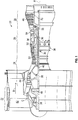
- FIG. 1 schematically illustrates a gas turbine engine 20.
- the gas turbine engine 20 is disclosed herein as a two-spool turbofan that generally incorporates a fan section 22, a compressor section 24, a combustor section 26 and a turbine section 28.
- Alternative engines might include an augmentor section (not shown) among other systems or features.
- the fan section 22 drives air along a bypass flow path B in a bypass duct, while the compressor section 24 drives air along a core flow path C for compression and communication into the combustor section 26 then expansion through the turbine section 28.
- the exemplary engine 20 generally includes a low speed spool 30 and a high speed spool 32 mounted for rotation about an engine central longitudinal axis A relative to an engine static structure 36 via several bearing systems 38. It should be understood that various bearing systems 38 at various locations may alternatively or additionally be provided, and the location of bearing systems 38 may be varied as appropriate to the application.
- the low speed spool 30 generally includes an inner shaft 40 that interconnects a fan 42, a low pressure compressor 44 and a low pressure turbine 46.
- the inner shaft 40 is connected to the fan 42 through a speed change mechanism, which in exemplary gas turbine engine 20 is illustrated as a geared architecture 48 to drive the fan 42 at a lower speed than the low speed spool 30.
- the high speed spool 32 includes an outer shaft 50 that interconnects a high pressure compressor 52 and high pressure turbine 54.
- a combustor 56 is arranged in exemplary gas turbine 20 between the high pressure compressor 52 and the high pressure turbine 54.
- An engine static structure 36 is arranged generally between the high pressure turbine 54 and the low pressure turbine 46.
- the engine static structure 36 further supports bearing systems 38 in the turbine section 28.
- the inner shaft 40 and the outer shaft 50 are concentric and rotate via bearing systems 38 about the engine central longitudinal axis A which is collinear with their longitudinal axes.
- each of the positions of the fan section 22, compressor section 24, combustor section 26, turbine section 28, and fan drive gear system 48 may be varied.
- gear system 48 may be located aft of combustor section 26 or even aft of turbine section 28, and fan section 22 may be positioned forward or aft of the location of gear system 48.
- the engine 20 in one example is a high-bypass geared aircraft engine.
- the engine 20 bypass ratio is greater than about six (6), with an example embodiment being greater than about ten (10)
- the geared architecture 48 is an epicyclic gear train, such as a planetary gear system or other gear system, with a gear reduction ratio of greater than about 2.3
- the low pressure turbine 46 has a pressure ratio that is greater than about five.
- the engine 20 bypass ratio is greater than about ten (10:1)
- the fan diameter is significantly larger than that of the low pressure compressor 44
- the low pressure turbine 46 has a pressure ratio that is greater than about five 5:1.
- Low pressure turbine 46 pressure ratio is pressure measured prior to inlet of low pressure turbine 46 as related to the pressure at the outlet of the low pressure turbine 46 prior to an exhaust nozzle.
- the geared architecture 48 may be an epicycle gear train, such as a planetary gear system or other gear system, with a gear reduction ratio of greater than about 2.3:1. It should be understood, however, that the above parameters are only exemplary of one embodiment of a geared architecture engine and that the present disclosure is applicable to other gas turbine engines including direct drive turbofans.
- the fan section 22 of the engine 20 is designed for a particular flight condition--typically cruise at about 0.8Mach and about 35,000 feet (10,688 meters).
- 'TSFC Thrust Specific Fuel Consumption
- Low fan pressure ratio is the pressure ratio across the fan blade alone, without a Fan Exit Guide Vane (“FEGV”) system.
- the low fan pressure ratio as disclosed herein according to one non-limiting embodiment is less than about 1.45.
- Low corrected fan tip speed is the actual fan tip speed in ft/sec divided by an industry standard temperature correction of [(Tram °R)/(518.7 °R)] 0.5 .
- the "Low corrected fan tip speed” as disclosed herein according to one non-limiting embodiment is less than about 1150 ft/second (350.5 m/sec).
- the turbine section 28 includes turbine disks 70 that each rotate about the axis A.
- the turbine section may include a plurality of stages each having a plurality of turbine blades mounted to a respective turbine disk of each stage.
- FIG. 2 illustrates a non-limiting perspective view of a damper seal or damper 72 for installation under platforms of adjacent turbine blades to reduce the vibratory response and provide frictional damping between the turbine blades as well as sealing the mate-face gap between blades.
- dampers may be made of sheet metal and conform to the underside of the platform when subjected to centrifugal loads in a high temperature environment due to their lack of stiffness out-of-plane.
- FIG. 3 is a side view of the damper seal or damper 72 illustrated in FIG. 2 .
- the damper seal or damper 72 may also be formed by direct metal laser sintering. Other manufacturing methods are possible.
- the damper seal 72 may be ductile enough to conform to a lower surface of the platform of the turbine blade. In one example, the damper seal 72 is substantially c-shaped.
- FIG. 4 a top perspective view of the damper seal 72 installed in adjacent turbine blades 74 is provided.
- the damper seal 72 is located in a neck cavity 76 of the turbine blades 74.
- the neck cavity 76 is defined as being located below the platform 78 of the turbine blade 74 and above the turbine disk the blades 74 are secured to.
- the damper seal 72 spans a space 80 between adjacent platforms 78 of adjacent turbine blades 74 to provide both damping and sealing and prevent the leakage of the cooling air from the cavity 76.
- the damper seal 72 imposes a normal load on the adjacent turbine blades 74 due to centrifugal force. The resulting frictional force created by the normal load produces damping to reduce a vibratory response.
- the damper seal 72 prevents the cooling air in the neck cavity 76 from leaking into the hot flow gas path between airfoils 82 of the turbine blades 74.
- a damper restraint 84 for retaining a damper seal 72 received in the cavity 76 is provided.
- the damper restraint 84 is a raised portion of material, rib, bump or feature located at a lateral or peripheral edge 86 of the platform 78.
- the damper restraint 84 is configured to engage a top portion or top surface portion 87 of the damper seal 72 that extends between a first end portion 88 and an opposing second end portion 90 of the damper seal 72. As illustrated, the first end portion 88 and the second end portion 90 extend towards a root 92 of the turbine blade 74 when the damper seal 72 is located in the cavity 76.
- the damper restraint 84 may be the combination of a raised feature, or rail or "bump" 93 located at the peripheral edge 86 under a suction side 94 of the platform 78 that runs along the peripheral or lateral edge 86 of the platform 78 of one blade or a first blade 74 and a raised feature, or rail or "bump” 95 located at the peripheral edge 86 under a pressure side 96 of the platform 78 of another blade or second blade 74 that is adjacent to the first blade 74.
- the pair of side by side raised features, rails or “bumps” 93, 95 provide the damper restraint 84 when they are side by side, which corresponds to the blades 74 being secured to the disk 70.
- FIG. 9 One non-limiting configuration is illustrated in FIG. 9 .
- the raised feature(s), or rail(s) or "bump(s)" 93, 95 may run along the entire length of edge 86.
- the raised feature(s), or rail(s) or “bump(s)" 93, 95 may run along a majority (e.g. greater than 50 %) of the entire length of edge 86.
- a majority e.g. greater than 50 %
- other variations less than 50% are also considered to be within the scope of various embodiments of the present disclosure.
- FIG. 8A the raised feature(s), or rail(s) or "bump(s)" 93, 95.
- the raised feature(s), or rail(s) or "bump(s)” 93, 95 may run intermittently and comprise an interrupted pattern or plurality of raised feature(s), or rail(s) or “bump(s)” 93, 95 that run along the entire length of edge 86 or any portion thereof (e.g., greater or less than 50%).
- the raised feature(s), or rail(s) or "bump(s)" 93, 95 may be located on only one side of the platform 78 (e.g., either the suction side 94 or the pressure side 96.
- damper restraint 84 By locating the damper restraint 84 on an interior surface 97 of the platform 78, a device is created that restrains the damper 84 from sliding toward the suction side of the pocket 76 when it is subject to tangential dynamic forces or rotational forces (e.g. induced by the orientation of the pocket (or broach angle) relative to the axis of rotation). Thus, undesired tangential movement of the damper 72 is prevented.
- the dashed lines 99 in FIGS. 8A and 8B illustrate the nominal position of the edges 101 (illustrated in FIG. 4 ) of the damper or damper seal 72.
- damper restraint 84 allows the potential elimination of weight increasing damper restraint devices as it only requires features at the peripheral edges of the platform. It can make new and current damper designs more effective without modifying the damper itself, and with only a minimal change to the blade platform that can be readily cast in.
- the feature can also be formed through some additive technique such as welding so that is can be used as a potential aftermarket fix to reduce the amount of damper deformation seen in service.
- one or more rails, or regions of generally raised material, running along the damper edge are formed on the underside of the blade suction side or pressure side platform by casting, machining, or some additive method.
- the restraint can run the entire length of the damper, or it can run for only a portion of it.
- the cross section of the rail may have a smooth or circular profile, or it can be square, triangular, or some other faceted shape.
- a radial component is added to the contact surface 87 of the damper seal 72.
- the concave surface formed in the top portion 87 which is caused by the heat and centripetal forces applied thereto, is adjacent to the surfaces of the damper restraint 84 formed by bumps or features 93, 95.
- This radial component is illustrated by curved line 103. This radial component improves dampening in the radial direction between the adjacent platforms 78 illustrated by arrows 105.
- the chamfers or bevels also restrain movement of the damper seal 72 in the directions of arrows 107. Accordingly, the platforms 78 with rails, bumps or features 93, 95 provide damping in a radial direction as well as preventing movement of the damper seal in a tangential direction(s) 107.
- the rails, bumps or features 93, 95 on the platform edge may be formed into existing or new designs.
- the rails, bumps or features 93, 95 may be formed on the platform 78 through some additive technique such as welding, and can be used as a potential aftermarket fix to reduce the amount of damper deformation seen in service.
- the rails, bumps or features 93, 95 may be included into a cast used to form new platforms 78.
- by using rails, bumps or features 93, 95 at peripheral edges 86 of the platform 78 there is no need for a special damper seal design.
- the rails, bumps or features 93, 95 at peripheral edges 86 of the platform 78 extend over a portion or the entire length of both the pressure side and suction side of the platform edges or alternatively only along one of the pressure side and suction side of the platform edges.
- the seal damper or damper seal 72 plastically deforms under centrifugal loading and high temperature.
- the damper seal 72 may be preformed with a concave top surface 87.
- the rails, bumps or features 93, 95 provide a contact surface between the underside of the platforms and the top surface 87 of the seal damper or damper seal 72 such that a system is provided for suppressing both radial and tangential vibration.
- Various embodiments of the present disclosure provide improved damper performance for blades that exhibit radial vibration.
- existing designs can be easily modified to incorporate the design.
- a potential aftermarket fix to correct excessive damper deformation is provided.
- the overall weight of the platform 78 may be reduced by limiting the amount of material necessary for the rails, bumps or features 93, 95.
- a device is created that restrains the damper seal 72 from sliding toward the suction side of the pocket 76 or the pressure side of the pocket 76 when it is subject to tangential dynamic forces or rotational forces (e.g. induced by the orientation of the pocket (or broach angle) relative to the axis of rotation).
- a device By creating a ridge of raised material, or a "rail", on the edge of the underside of either or both platforms, a device is created that will restrain the damper from sliding toward the suction side of the pocket.
- the damper will conform over and around the rail preventing its bulk motion.
- the damper doesn't need to be pre-conformed, but it can be.
- This design feature allows the potential elimination of weight increasing damper restraint devices. It can make new and current damper designs more effective without modifying the damper itself, and with only a minimal change to the blade platform that can be readily cast in.
- the raised material can be designed in a way so that the system is effective in damping radial vibration (e.g. if the rail and the conformed damper share a contact surface with a component in the radial direction).
Landscapes
- Engineering & Computer Science (AREA)
- Mechanical Engineering (AREA)
- General Engineering & Computer Science (AREA)
- Structures Of Non-Positive Displacement Pumps (AREA)
- Turbine Rotor Nozzle Sealing (AREA)
Abstract
Description
- Exemplary embodiments of the present disclosure are directed to turbine blades and/or compressor blades for a gas turbine engine and methods for restraining a damper of a turbine blade and/or compressor blade.
- A gas turbine engine includes a plurality of turbine blades and compressor blades each received in a slot of a disk. The blades are exposed to aerodynamic forces that can result in vibratory stresses. A seal damper or damper can be located under platforms of adjacent blades to reduce the vibratory response and provide frictional damping between the blades. The seal damper slides on an underside of the platforms. The seal damper is made of a material that is dissimilar from the material of the blades. When the vibratory motions of adjacent blades oppose each other (that is, occur out of phase), the seal damper slides to absorb the energy of vibration.
- Seal dampers work by conforming to the underside of blade platforms to seal the mate-face gap between blades and provide frictional damping to suppress the vibratory response of the blades to excitations in the engine. These dampers are typically made of sheet metal and have been shown to readily conform to the underside of the platform when subjected to centrifugal loads in a high temperature environment due to their lack of stiffness out-of-plane.
- Sometimes seal dampers will experience unintentional bulk tangential movement relative to the damper pocket due to the dynamic forces imposed on it by the rotation of the blades and the lack of sufficient restraint devices. To maximize damper efficiency, damper configurations are sought which minimize weight and maximize damper stiffness. Thus it is desirable to limit the number of weight increasing restraint devices on the damper (i.e. features which interlock with "damper tabs", "damper nubs", or some other feature of the under-platform geometry, or "bathtub" type designs that pre-conform to under-platform filleting).
- Accordingly, it is desirable to provide a method and apparatus for restraining movement of a damper with respect to a blade platform.
- In one embodiment, a blade for a gas turbine engine is provided. The blade has: a root; a platform located between the root and the blade, wherein the platform defines a cavity; a damper restraint located at a peripheral edge of the platform, wherein the damper restraint is a raised feature extending along at least a portion of the peripheral edge of the platform.
- In addition to one or more of the features described above, or as an alternative to any of the foregoing embodiments, the damper restraint may be a pair of raised features extending along at least a portion of opposing peripheral edges of the platform.
- In addition to one or more of the features described above, or as an alternative to any of the foregoing embodiments, the damper restraint may be a plurality of raised features extending along at least a portion of one of the peripheral edges of the platform.
- In addition to one or more of the features described above, or as an alternative to any of the foregoing embodiments, the damper restraint may extend along a suction side of the platform.
- In addition to one or more of the features described above, or as an alternative to any of the foregoing embodiments, the damper restraint may extend along a pressure side of the platform.
- In addition to one or more of the features described above, or as an alternative to any of the foregoing embodiments, the blade may be a turbine blade.
- In addition to one or more of the features described above, or as an alternative to any of the foregoing embodiments, the blade may be a compressor blade.
- In yet another embodiment, a gas turbine engine is provided. The gas turbine engine has: a disk; a plurality of blades secured to the disk, each of the blades having a root, and a platform located between the root and the blade, wherein a seam is defined by adjoining platforms of each of the blades when they are secured to the disk, wherein the platform of each of the plurality of blades defines a cavity and has a damper restraint retaining movement of a damper seal received in the cavity, wherein the damper seal covers the seam and a top surface portion of the damper seal engages the damper restraint.
- In addition to one or more of the features described above, or as an alternative to any of the foregoing embodiments, the damper restraint may be a pair of raised features extending along at least a portion of opposing peripheral edges of the platform.
- In addition to one or more of the features described above, or as an alternative to any of the foregoing embodiments, the damper restraint may be a plurality of raised features extending along at least a portion of one of the peripheral edges of the platform.
- In addition to one or more of the features described above, or as an alternative to any of the foregoing embodiments, the damper restraint may extend along a suction side of the platform.
- In addition to one or more of the features described above, or as an alternative to any of the foregoing embodiments, the damper restraint may extend along a pressure side of the platform.
- In addition to one or more of the features described above, or as an alternative to any of the foregoing embodiments, the blade may be a turbine blade.
- In addition to one or more of the features described above, or as an alternative to any of the foregoing embodiments, the blade may be a compressor blade.
- In addition to one or more of the features described above, or as an alternative to any of the foregoing embodiments, the damper seal may be formed from stamped sheet metal and a top surface portion of the damper seal contacts the damper restraint.
- In addition to one or more of the features described above, or as an alternative to any of the foregoing embodiments, the damper restraint may be a pair of raised features extending along at least a portion of opposing peripheral edges of the platform.
- In addition to one or more of the features described above, or as an alternative to any of the foregoing embodiments, the damper restraint may be a plurality of raised features extending along at least a portion of one of the peripheral edges of the platform.
- In addition to one or more of the features described above, or as an alternative to any of the foregoing embodiments, the damper restraint may extend along a suction side of the platform or a pressure side of the platform.
- In yet another embodiment, a method of damping vibrations between adjoining blades of a gas turbine engine is provided. The method includes the steps of: locating a damper seal adjacent to a seam defined by adjoining platforms of blades of the gas turbine engine; and restraining the movement of the damper seal in a direction away from the seam by retaining the damper seal with at least one protrusion extending along a peripheral edge of at least one of the adjoining platforms.
- In addition to one or more of the features described above, or as an alternative to any of the foregoing embodiments, the damper seal may be formed from stamped sheet metal and the blade may be either a compressor blade or a turbine blade and the at least one protrusion engaging a top surface of the damper seal.
- The following descriptions are by way of example only, and should not be considered limiting in any way. With reference to the exemplary accompanying drawings, like elements are numbered alike:
-
FIG. 1 is a partial cross sectional view of a gas turbine engine; -
FIG. 2 is a non-limiting perspective view of a damper or damper seal; -
FIG. 3 is a side view of the damper seal illustrated inFIG. 2 ; -
FIG. 4 is a perspective view of a damper seal installed between two adjacent turbine blades; -
FIG. 5 is a side view of a turbine blade with an under platform damper restraint; -
FIG. 6 is a view along lines 6-6 ofFIG. 5 ; -
FIG. 7 is a side view of a turbine blade with an under platform damper restraint; -
FIG. 8A is a view along lines 8-8 ofFIG. 7 according to one embodiment; -
FIG. 8B is a view along lines 8-8 ofFIG. 7 according to another embodiment; and -
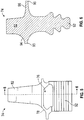
FIG. 9 is a cross sectional view illustrating an under platform damper restraint and a damper according to one embodiment. - A detailed description of one or more embodiments of the disclosed apparatus and method are presented herein by way of exemplification and not limitation with reference to the Figures.
-
FIG. 1 schematically illustrates agas turbine engine 20. Thegas turbine engine 20 is disclosed herein as a two-spool turbofan that generally incorporates afan section 22, acompressor section 24, acombustor section 26 and aturbine section 28. Alternative engines might include an augmentor section (not shown) among other systems or features. Thefan section 22 drives air along a bypass flow path B in a bypass duct, while thecompressor section 24 drives air along a core flow path C for compression and communication into thecombustor section 26 then expansion through theturbine section 28. Although depicted as a two-spool turbofan gas turbine engine in the disclosed non-limiting embodiment, it should be understood that the concepts described herein are not limited to use with two-spool turbofans as the teachings may be applied to other types of turbine engines including three-spool architectures. - The
exemplary engine 20 generally includes alow speed spool 30 and ahigh speed spool 32 mounted for rotation about an engine central longitudinal axis A relative to an enginestatic structure 36 viaseveral bearing systems 38. It should be understood thatvarious bearing systems 38 at various locations may alternatively or additionally be provided, and the location ofbearing systems 38 may be varied as appropriate to the application. - The
low speed spool 30 generally includes aninner shaft 40 that interconnects afan 42, alow pressure compressor 44 and alow pressure turbine 46. Theinner shaft 40 is connected to thefan 42 through a speed change mechanism, which in exemplarygas turbine engine 20 is illustrated as a gearedarchitecture 48 to drive thefan 42 at a lower speed than thelow speed spool 30. Thehigh speed spool 32 includes anouter shaft 50 that interconnects ahigh pressure compressor 52 andhigh pressure turbine 54. Acombustor 56 is arranged inexemplary gas turbine 20 between thehigh pressure compressor 52 and thehigh pressure turbine 54. An enginestatic structure 36 is arranged generally between thehigh pressure turbine 54 and thelow pressure turbine 46. The enginestatic structure 36 furthersupports bearing systems 38 in theturbine section 28. Theinner shaft 40 and theouter shaft 50 are concentric and rotate via bearingsystems 38 about the engine central longitudinal axis A which is collinear with their longitudinal axes. - The core airflow is compressed by the
low pressure compressor 44 then thehigh pressure compressor 52, mixed and burned with fuel in thecombustor 56, then expanded over thehigh pressure turbine 54 andlow pressure turbine 46. Theturbines low speed spool 30 andhigh speed spool 32 in response to the expansion. It will be appreciated that each of the positions of thefan section 22,compressor section 24,combustor section 26,turbine section 28, and fandrive gear system 48 may be varied. For example,gear system 48 may be located aft ofcombustor section 26 or even aft ofturbine section 28, andfan section 22 may be positioned forward or aft of the location ofgear system 48. - The
engine 20 in one example is a high-bypass geared aircraft engine. In a further example, theengine 20 bypass ratio is greater than about six (6), with an example embodiment being greater than about ten (10), the gearedarchitecture 48 is an epicyclic gear train, such as a planetary gear system or other gear system, with a gear reduction ratio of greater than about 2.3 and thelow pressure turbine 46 has a pressure ratio that is greater than about five. In one disclosed embodiment, theengine 20 bypass ratio is greater than about ten (10:1), the fan diameter is significantly larger than that of thelow pressure compressor 44, and thelow pressure turbine 46 has a pressure ratio that is greater than about five 5:1.Low pressure turbine 46 pressure ratio is pressure measured prior to inlet oflow pressure turbine 46 as related to the pressure at the outlet of thelow pressure turbine 46 prior to an exhaust nozzle. The gearedarchitecture 48 may be an epicycle gear train, such as a planetary gear system or other gear system, with a gear reduction ratio of greater than about 2.3:1. It should be understood, however, that the above parameters are only exemplary of one embodiment of a geared architecture engine and that the present disclosure is applicable to other gas turbine engines including direct drive turbofans. - A significant amount of thrust is provided by the bypass flow B due to the high bypass ratio. The
fan section 22 of theengine 20 is designed for a particular flight condition--typically cruise at about 0.8Mach and about 35,000 feet (10,688 meters). The flight condition of 0.8 Mach and 35,000 ft (10,688 meters), with the engine at its best fuel consumption--also known as "bucket cruise Thrust Specific Fuel Consumption ('TSFC)"--is the industry standard parameter of lbm of fuel being burned divided by lbf of thrust the engine produces at that minimum point. "Low fan pressure ratio" is the pressure ratio across the fan blade alone, without a Fan Exit Guide Vane ("FEGV") system. The low fan pressure ratio as disclosed herein according to one non-limiting embodiment is less than about 1.45. "Low corrected fan tip speed" is the actual fan tip speed in ft/sec divided by an industry standard temperature correction of [(Tram °R)/(518.7 °R)]0.5. The "Low corrected fan tip speed" as disclosed herein according to one non-limiting embodiment is less than about 1150 ft/second (350.5 m/sec). - The
turbine section 28 includesturbine disks 70 that each rotate about the axis A. As is known in the related arts, the turbine section may include a plurality of stages each having a plurality of turbine blades mounted to a respective turbine disk of each stage. -
FIG. 2 illustrates a non-limiting perspective view of a damper seal ordamper 72 for installation under platforms of adjacent turbine blades to reduce the vibratory response and provide frictional damping between the turbine blades as well as sealing the mate-face gap between blades. These dampers may be made of sheet metal and conform to the underside of the platform when subjected to centrifugal loads in a high temperature environment due to their lack of stiffness out-of-plane. Although the present disclosure is described with reference to turbine blades it is understood that anyone of the various embodiments disclosed herein may be applied to platforms of adjacent compressor blades of a compressor disk or rotor to reduce the vibratory response and provide frictional damping between the compressor blades as well as sealing the mate-face gap between blades. Therefore and when referring toFIGS. 4-9 these may alternatively be referred to as compressor blades. Moreover, various embodiments of the present disclosure may be applied in any other application where there is a desire to reduce the vibratory response and provide frictional damping between two adjoining items that are rotated about an axis as sealing the mate-face gap between the two adjoining items.FIG. 3 is a side view of the damper seal ordamper 72 illustrated inFIG. 2 . - The damper seal or
damper 72 may also be formed by direct metal laser sintering. Other manufacturing methods are possible. Thedamper seal 72 may be ductile enough to conform to a lower surface of the platform of the turbine blade. In one example, thedamper seal 72 is substantially c-shaped. - Referring now to
FIG. 4 , a top perspective view of thedamper seal 72 installed inadjacent turbine blades 74 is provided. Thedamper seal 72 is located in aneck cavity 76 of theturbine blades 74. As illustrated in at leastFIGS. 5-9 , theneck cavity 76 is defined as being located below theplatform 78 of theturbine blade 74 and above the turbine disk theblades 74 are secured to. - As illustrated, the
damper seal 72 spans aspace 80 betweenadjacent platforms 78 ofadjacent turbine blades 74 to provide both damping and sealing and prevent the leakage of the cooling air from thecavity 76. Thedamper seal 72 imposes a normal load on theadjacent turbine blades 74 due to centrifugal force. The resulting frictional force created by the normal load produces damping to reduce a vibratory response. Thedamper seal 72 prevents the cooling air in theneck cavity 76 from leaking into the hot flow gas path betweenairfoils 82 of theturbine blades 74. - In accordance with an embodiment of the present disclosure, a
damper restraint 84 for retaining adamper seal 72 received in thecavity 76 is provided. In one embodiment, thedamper restraint 84 is a raised portion of material, rib, bump or feature located at a lateral orperipheral edge 86 of theplatform 78. - The
damper restraint 84 is configured to engage a top portion ortop surface portion 87 of thedamper seal 72 that extends between afirst end portion 88 and an opposingsecond end portion 90 of thedamper seal 72. As illustrated, thefirst end portion 88 and thesecond end portion 90 extend towards aroot 92 of theturbine blade 74 when thedamper seal 72 is located in thecavity 76. - In one embodiment and as illustrated in the attached FIGS., the
damper restraint 84 may be the combination of a raised feature, or rail or "bump" 93 located at theperipheral edge 86 under asuction side 94 of theplatform 78 that runs along the peripheral orlateral edge 86 of theplatform 78 of one blade or afirst blade 74 and a raised feature, or rail or "bump" 95 located at theperipheral edge 86 under apressure side 96 of theplatform 78 of another blade orsecond blade 74 that is adjacent to thefirst blade 74. As such, the pair of side by side raised features, rails or "bumps" 93, 95 provide thedamper restraint 84 when they are side by side, which corresponds to theblades 74 being secured to thedisk 70. One non-limiting configuration is illustrated inFIG. 9 . - In one embodiment and as illustrated in
FIG. 8A , the raised feature(s), or rail(s) or "bump(s)" 93, 95, may run along the entire length ofedge 86. Alternatively, the raised feature(s), or rail(s) or "bump(s)" 93, 95, may run along a majority (e.g. greater than 50 %) of the entire length ofedge 86. Of course, other variations less than 50% are also considered to be within the scope of various embodiments of the present disclosure. In yet another embodiment and referring now toFIG. 8B the raised feature(s), or rail(s) or "bump(s)" 93, 95, may run intermittently and comprise an interrupted pattern or plurality of raised feature(s), or rail(s) or "bump(s)" 93, 95 that run along the entire length ofedge 86 or any portion thereof (e.g., greater or less than 50%). - In yet another embodiment the raised feature(s), or rail(s) or "bump(s)" 93, 95 may be located on only one side of the platform 78 (e.g., either the
suction side 94 or thepressure side 96. - By locating the
damper restraint 84 on aninterior surface 97 of theplatform 78, a device is created that restrains thedamper 84 from sliding toward the suction side of thepocket 76 when it is subject to tangential dynamic forces or rotational forces (e.g. induced by the orientation of the pocket (or broach angle) relative to the axis of rotation). Thus, undesired tangential movement of thedamper 72 is prevented. - The dashed
lines 99 inFIGS. 8A and 8B illustrate the nominal position of the edges 101 (illustrated inFIG. 4 ) of the damper ordamper seal 72. - This design feature (e.g., damper restraint 84) allows the potential elimination of weight increasing damper restraint devices as it only requires features at the peripheral edges of the platform. It can make new and current damper designs more effective without modifying the damper itself, and with only a minimal change to the blade platform that can be readily cast in. The feature can also be formed through some additive technique such as welding so that is can be used as a potential aftermarket fix to reduce the amount of damper deformation seen in service.
- Furthermore and in one embodiment, one or more rails, or regions of generally raised material, running along the damper edge are formed on the underside of the blade suction side or pressure side platform by casting, machining, or some additive method. The restraint can run the entire length of the damper, or it can run for only a portion of it. The cross section of the rail may have a smooth or circular profile, or it can be square, triangular, or some other faceted shape.
- By bending the
top portion 87 about the protrusion formed by the bumps or features 93, 95, a radial component is added to thecontact surface 87 of thedamper seal 72. In other words, the concave surface formed in thetop portion 87, which is caused by the heat and centripetal forces applied thereto, is adjacent to the surfaces of thedamper restraint 84 formed by bumps or features 93, 95. This radial component is illustrated bycurved line 103. This radial component improves dampening in the radial direction between theadjacent platforms 78 illustrated byarrows 105. - In addition, the chamfers or bevels also restrain movement of the
damper seal 72 in the directions ofarrows 107. Accordingly, theplatforms 78 with rails, bumps or features 93, 95 provide damping in a radial direction as well as preventing movement of the damper seal in a tangential direction(s) 107. - In one embodiment, the rails, bumps or features 93, 95 on the platform edge may be formed into existing or new designs. In other words, the rails, bumps or features 93, 95 may be formed on the
platform 78 through some additive technique such as welding, and can be used as a potential aftermarket fix to reduce the amount of damper deformation seen in service. Or for new designs, the rails, bumps or features 93, 95 may be included into a cast used to formnew platforms 78. Moreover, by using rails, bumps or features 93, 95 atperipheral edges 86 of theplatform 78, there is no need for a special damper seal design. In this way, the use of rails, bumps or features 93, 95 atperipheral edges 86 of theplatform 78 can be particularly useful in the aftermarket as a way of correcting unintended damper operation. For example an existingplatform 78 can be worked on through any suitable process to add rails, bumps or features 93, 95 atperipheral edges 86 of theplatform 78. - In accordance with one non-limiting embodiment, the rails, bumps or features 93, 95 at
peripheral edges 86 of theplatform 78 extend over a portion or the entire length of both the pressure side and suction side of the platform edges or alternatively only along one of the pressure side and suction side of the platform edges. The seal damper ordamper seal 72 plastically deforms under centrifugal loading and high temperature. Alternatively, thedamper seal 72 may be preformed with a concavetop surface 87. The rails, bumps or features 93, 95 provide a contact surface between the underside of the platforms and thetop surface 87 of the seal damper ordamper seal 72 such that a system is provided for suppressing both radial and tangential vibration. - Various embodiments of the present disclosure provide improved damper performance for blades that exhibit radial vibration. In addition, existing designs can be easily modified to incorporate the design. As such, a potential aftermarket fix to correct excessive damper deformation is provided. Still further, the overall weight of the
platform 78 may be reduced by limiting the amount of material necessary for the rails, bumps or features 93, 95. Moreover, by locating the rails, bumps or features 93, 95 on an interior surface of theplatform 78, a device is created that restrains thedamper seal 72 from sliding toward the suction side of thepocket 76 or the pressure side of thepocket 76 when it is subject to tangential dynamic forces or rotational forces (e.g. induced by the orientation of the pocket (or broach angle) relative to the axis of rotation). - By creating a ridge of raised material, or a "rail", on the edge of the underside of either or both platforms, a device is created that will restrain the damper from sliding toward the suction side of the pocket. The damper will conform over and around the rail preventing its bulk motion. The damper doesn't need to be pre-conformed, but it can be. This design feature allows the potential elimination of weight increasing damper restraint devices. It can make new and current damper designs more effective without modifying the damper itself, and with only a minimal change to the blade platform that can be readily cast in. Additionally, the raised material can be designed in a way so that the system is effective in damping radial vibration (e.g. if the rail and the conformed damper share a contact surface with a component in the radial direction).
- The term "about" is intended to include the degree of error associated with measurement of the particular quantity based upon the equipment available at the time of filing the application. For example, "about" can include a range of ± 8% or 5%, or 2% of a given value.
- The terminology used herein is for the purpose of describing particular embodiments only and is not intended to be limiting of the present disclosure. As used herein, the singular forms "a", "an" and "the" are intended to include the plural forms as well, unless the context clearly indicates otherwise. It will be further understood that the terms "comprises" and/or "comprising," when used in this specification, specify the presence of stated features, integers, steps, operations, elements, and/or components, but do not preclude the presence or addition of one or more other features, integers, steps, operations, element components, and/or groups thereof.
- While the present disclosure has been described with reference to an exemplary embodiment or embodiments, it will be understood by those skilled in the art that various changes may be made and equivalents may be substituted for elements thereof without departing from the scope of the present disclosure as set out in the claims. In addition, many modifications may be made to adapt a particular situation or material to the teachings of the present disclosure as set out in the claims without departing from the essential scope thereof. Therefore, it is intended that the present disclosure not be limited to the particular embodiment disclosed as the best mode contemplated for carrying out this present disclosure, but that the present disclosure will include all embodiments falling within the scope of the claims.
- Further embodiments of the present invention will now be described according to the following numbered clauses.
- 1. A gas turbine engine, comprising:
- a disk;
- a plurality of blades secured to the disk, each of the blades having a root, and a platform located between the root and the blade, wherein a seam is defined by adjoining platforms of each of the blades when they are secured to the disk, wherein the platform of each of the plurality of blades defines a cavity and has a damper restraint retaining movement of a damper seal received in the cavity, wherein the damper seal covers the seam and a top surface portion of the damper seal engages the damper restraint.
- 2. The gas turbine engine as recited in clause 1, wherein the damper restraint is a pair of raised features extending along at least a portion of opposing peripheral edges of the platform.
- 3. The gas turbine engine as recited in clause 1, wherein the damper restraint is a plurality of raised features extending along at least a portion of one of the peripheral edges of the platform.
- 4. The gas turbine engine as recited in clause 1, wherein the damper restraint extends along a suction side of the platform.
- 5. The gas turbine engine as recited in clause 1, wherein the damper restraint extends along a pressure side of the platform.
- 6. The gas turbine engine as recited in clause 1, wherein the blade is a turbine blade.
- 7. The gas turbine engine as recited in clause 1, wherein the blade is a compressor blade.
- 8. The gas turbine engine as recited in clause 1, wherein the damper seal is formed from stamped sheet metal and a top surface portion of the damper seal contacts the damper restraint.
- 9. The gas turbine engine as recited in
clause 8, wherein the damper restraint is a pair of raised features extending along at least a portion of opposing peripheral edges of the platform. - 10. The gas turbine engine as recited in
clause 8, wherein the damper restraint is a plurality of raised features extending along at least a portion of one of the peripheral edges of the platform. - 11. The gas turbine engine as recited in
clause 8, wherein the damper restraint extends along a suction side of the platform or a pressure side of the platform.
Claims (11)
- A blade (74) for a gas turbine engine (20), comprising:a root (92);a platform (78) located between the root and the blade, wherein the platform defines a cavity (76);a damper restraint (84) located at a peripheral edge (86) of the platform,wherein the damper restraint is a raised feature (93; 95) extending along at least a portion of the peripheral edge of the platform.
- The blade as claimed in claim 1, wherein the damper restraint is a pair of raised features extending along at least a portion of opposing peripheral edges of the platform.
- The blade as claimed in claim 1, wherein the damper restraint is a plurality of raised features (93, 95) extending along at least a portion of one of the peripheral edges (86) of the platform.
- The blade as claimed in claim 1 or 3, wherein the damper restraint extends along a suction side (94) of the platform.
- The blade as claimed in claim 1 or 3, wherein the damper restraint extends along a pressure side (96) of the platform.
- The blade as claimed in any preceding claim, wherein the blade is a turbine blade.
- The blade as claimed in any of claims 1 to 5, wherein the blade is a compressor blade.
- A gas turbine engine, comprising:a disk (70);a plurality of blades as claimed in any preceding claim secured to the disk,wherein a seam (80) is defined by adjoining platforms of each of the blades when they are secured to the disk, wherein each damper restraint retains movement of a damper seal (72) received in the cavity, wherein the damper seal covers the seam and a top surface portion (87) of the damper seal engages the damper restraint.
- The gas turbine engine as claimed in claim 8, wherein the damper seal is formed from stamped sheet metal and the top surface portion of the damper seal contacts the damper restraint.
- A method of damping vibrations between adjoining blades (74) of a gas turbine engine (20), comprising:locating a damper seal (72) adjacent to a seam (80) defined by adjoining platforms (78) of blades (74) of the gas turbine engine (20); andrestraining the movement of the damper seal in a direction away from the seam by retaining the damper seal with at least one protrusion (93; 95) extending along a peripheral edge (86) of at least one of the adjoining platforms.
- The method as claimed in claim 10, wherein the damper seal is formed from stamped sheet metal and the blade is either a compressor blade or a turbine blade and the at least one protrusion engages a top surface (87) of the damper seal.
Applications Claiming Priority (1)
| Application Number | Priority Date | Filing Date | Title |
|---|---|---|---|
| US15/397,519 US10677073B2 (en) | 2017-01-03 | 2017-01-03 | Blade platform with damper restraint |
Publications (2)
| Publication Number | Publication Date |
|---|---|
| EP3342985A1 true EP3342985A1 (en) | 2018-07-04 |
| EP3342985B1 EP3342985B1 (en) | 2025-02-26 |
Family
ID=60923382
Family Applications (1)
| Application Number | Title | Priority Date | Filing Date |
|---|---|---|---|
| EP18150242.8A Active EP3342985B1 (en) | 2017-01-03 | 2018-01-03 | Disk for a gas turbine engine and method of damping vibrations between adjacent blades of a gas turbine engine |
Country Status (2)
| Country | Link |
|---|---|
| US (1) | US10677073B2 (en) |
| EP (1) | EP3342985B1 (en) |
Cited By (1)
| Publication number | Priority date | Publication date | Assignee | Title |
|---|---|---|---|---|
| EP3832072A1 (en) * | 2019-12-06 | 2021-06-09 | Raytheon Technologies Corporation | Pre-formed faceted turbine blade damper seal |
Families Citing this family (8)
| Publication number | Priority date | Publication date | Assignee | Title |
|---|---|---|---|---|
| US10662784B2 (en) | 2016-11-28 | 2020-05-26 | Raytheon Technologies Corporation | Damper with varying thickness for a blade |
| US10731479B2 (en) | 2017-01-03 | 2020-08-04 | Raytheon Technologies Corporation | Blade platform with damper restraint |
| US10907491B2 (en) * | 2017-11-30 | 2021-02-02 | General Electric Company | Sealing system for a rotary machine and method of assembling same |
| JP7064076B2 (en) * | 2018-03-27 | 2022-05-10 | 三菱重工業株式会社 | How to tune turbine blades, turbines, and natural frequencies of turbine blades |
| US10975714B2 (en) * | 2018-11-22 | 2021-04-13 | Pratt & Whitney Canada Corp. | Rotor assembly with blade sealing tab |
| US11486261B2 (en) | 2020-03-31 | 2022-11-01 | General Electric Company | Turbine circumferential dovetail leakage reduction |
| US11834960B2 (en) | 2022-02-18 | 2023-12-05 | General Electric Company | Methods and apparatus to reduce deflection of an airfoil |
| US12180857B2 (en) * | 2023-04-21 | 2024-12-31 | Rtx Corporation | Turbine airfoil attachment with serration profile |
Citations (1)
| Publication number | Priority date | Publication date | Assignee | Title |
|---|---|---|---|---|
| US4029436A (en) * | 1975-06-17 | 1977-06-14 | United Technologies Corporation | Blade root feather seal |
Family Cites Families (51)
| Publication number | Priority date | Publication date | Assignee | Title |
|---|---|---|---|---|
| US3709631A (en) | 1971-03-18 | 1973-01-09 | Caterpillar Tractor Co | Turbine blade seal arrangement |
| US3752598A (en) * | 1971-11-17 | 1973-08-14 | United Aircraft Corp | Segmented duct seal |
| US4183720A (en) | 1978-01-03 | 1980-01-15 | The United States Of America As Represented By The Secretary Of The Air Force | Composite fan blade platform double wedge centrifugal seal |
| US4580946A (en) * | 1984-11-26 | 1986-04-08 | General Electric Company | Fan blade platform seal |
| FR2665726B1 (en) * | 1990-08-08 | 1993-07-02 | Snecma | TURBOMACHINE BLOWER WITH DYNAMIC CAM SHOCK ABSORBER. |
| FR2669686B1 (en) | 1990-11-28 | 1994-09-02 | Snecma | BLOWER ROTOR WITH BLADES WITHOUT PLATFORMS AND SHOES RECONSTRUCTING THE VEIN PROFILE. |
| US5226784A (en) | 1991-02-11 | 1993-07-13 | General Electric Company | Blade damper |
| US5156528A (en) * | 1991-04-19 | 1992-10-20 | General Electric Company | Vibration damping of gas turbine engine buckets |
| US5313786A (en) | 1992-11-24 | 1994-05-24 | United Technologies Corporation | Gas turbine blade damper |
| US5415526A (en) | 1993-11-19 | 1995-05-16 | Mercadante; Anthony J. | Coolable rotor assembly |
| US5478207A (en) | 1994-09-19 | 1995-12-26 | General Electric Company | Stable blade vibration damper for gas turbine engine |
| JPH09303107A (en) | 1996-05-13 | 1997-11-25 | Toshiba Corp | Gas turbine blade sealing device |
| US5827047A (en) | 1996-06-27 | 1998-10-27 | United Technologies Corporation | Turbine blade damper and seal |
| US5820346A (en) | 1996-12-17 | 1998-10-13 | General Electric Company | Blade damper for a turbine engine |
| US5785499A (en) | 1996-12-24 | 1998-07-28 | United Technologies Corporation | Turbine blade damper and seal |
| US6171058B1 (en) | 1999-04-01 | 2001-01-09 | General Electric Company | Self retaining blade damper |
| DE10014198A1 (en) | 2000-03-22 | 2001-09-27 | Alstom Power Nv | Blading with damping elements |
| DE10022244A1 (en) | 2000-05-08 | 2001-11-15 | Alstom Power Nv | Blade arrangement with damping elements |
| JP2002201913A (en) | 2001-01-09 | 2002-07-19 | Mitsubishi Heavy Ind Ltd | Split wall of gas turbine and shroud |
| JP4748345B2 (en) * | 2001-07-11 | 2011-08-17 | 株式会社Ihi | Jet engine fan platform seal |
| WO2003014529A1 (en) * | 2001-08-03 | 2003-02-20 | Hitachi, Ltd. | Turbine moving vane |
| JP2003056490A (en) | 2001-08-21 | 2003-02-26 | Ishikawajima Harima Heavy Ind Co Ltd | Seal structure between blade platforms |
| GB0304329D0 (en) | 2003-02-26 | 2003-04-02 | Rolls Royce Plc | Damper seal |
| US6851932B2 (en) | 2003-05-13 | 2005-02-08 | General Electric Company | Vibration damper assembly for the buckets of a turbine |
| DE102004023130A1 (en) | 2004-05-03 | 2005-12-01 | Rolls-Royce Deutschland Ltd & Co Kg | Sealing and damping system for turbine blades |
| US7121802B2 (en) * | 2004-07-13 | 2006-10-17 | General Electric Company | Selectively thinned turbine blade |
| JP2006125372A (en) * | 2004-11-01 | 2006-05-18 | Mitsubishi Heavy Ind Ltd | Vibration control structure of rotary machine blade and rotary machine |
| SE0502644L (en) | 2005-12-02 | 2007-06-03 | Siemens Ag | Cooling platforms for turbine blades in turbines |
| US7534090B2 (en) | 2006-06-13 | 2009-05-19 | General Electric Company | Enhanced bucket vibration system |
| US7762773B2 (en) * | 2006-09-22 | 2010-07-27 | Siemens Energy, Inc. | Turbine airfoil cooling system with platform edge cooling channels |
| EP1925781A1 (en) | 2006-11-23 | 2008-05-28 | Siemens Aktiengesellschaft | Blade arrangement |
| WO2009018893A1 (en) * | 2007-08-03 | 2009-02-12 | Khs Ag | Device and method for printing containers |
| FR2927357B1 (en) | 2008-02-12 | 2013-09-20 | Snecma | DEVICE FOR DAMPING VIBRATIONS BETWEEN TWO WHEELS OF WHEEL TURBOMACHINE |
| EP2098687A1 (en) | 2008-03-07 | 2009-09-09 | Siemens Aktiengesellschaft | Rotor for a turbo engine |
| GB0814018D0 (en) * | 2008-08-01 | 2008-09-10 | Rolls Royce Plc | Vibration damper |
| US8240987B2 (en) | 2008-08-15 | 2012-08-14 | United Technologies Corp. | Gas turbine engine systems involving baffle assemblies |
| GB2463036B (en) | 2008-08-29 | 2011-04-20 | Rolls Royce Plc | A blade arrangement |
| GB0816467D0 (en) * | 2008-09-10 | 2008-10-15 | Rolls Royce Plc | Turbine blade damper arrangement |
| US8820754B2 (en) * | 2010-06-11 | 2014-09-02 | Siemens Energy, Inc. | Turbine blade seal assembly |
| US9022727B2 (en) | 2010-11-15 | 2015-05-05 | Mtu Aero Engines Gmbh | Rotor for a turbo machine |
| FR2974387B1 (en) * | 2011-04-19 | 2015-11-20 | Snecma | TURBINE WHEEL FOR A TURBOMACHINE |
| US10113434B2 (en) | 2012-01-31 | 2018-10-30 | United Technologies Corporation | Turbine blade damper seal |
| US9175570B2 (en) | 2012-04-24 | 2015-11-03 | United Technologies Corporation | Airfoil including member connected by articulated joint |
| US9587495B2 (en) | 2012-06-29 | 2017-03-07 | United Technologies Corporation | Mistake proof damper pocket seals |
| US20160061048A1 (en) | 2013-03-25 | 2016-03-03 | United Technologies Corporation | Rotor blade with l-shaped feather seal |
| JP5863894B2 (en) * | 2014-07-09 | 2016-02-17 | 三菱日立パワーシステムズ株式会社 | Rotor body and rotating machine |
| US9822644B2 (en) | 2015-02-27 | 2017-11-21 | Pratt & Whitney Canada Corp. | Rotor blade vibration damper |
| US9810075B2 (en) | 2015-03-20 | 2017-11-07 | United Technologies Corporation | Faceted turbine blade damper-seal |
| US10662784B2 (en) | 2016-11-28 | 2020-05-26 | Raytheon Technologies Corporation | Damper with varying thickness for a blade |
| US10731479B2 (en) | 2017-01-03 | 2020-08-04 | Raytheon Technologies Corporation | Blade platform with damper restraint |
| US20180187558A1 (en) | 2017-01-03 | 2018-07-05 | United Technologies Corporation | Blade platform with chamfer |
-
2017
- 2017-01-03 US US15/397,519 patent/US10677073B2/en active Active
-
2018
- 2018-01-03 EP EP18150242.8A patent/EP3342985B1/en active Active
Patent Citations (1)
| Publication number | Priority date | Publication date | Assignee | Title |
|---|---|---|---|---|
| US4029436A (en) * | 1975-06-17 | 1977-06-14 | United Technologies Corporation | Blade root feather seal |
Cited By (2)
| Publication number | Priority date | Publication date | Assignee | Title |
|---|---|---|---|---|
| EP3832072A1 (en) * | 2019-12-06 | 2021-06-09 | Raytheon Technologies Corporation | Pre-formed faceted turbine blade damper seal |
| US11377967B2 (en) | 2019-12-06 | 2022-07-05 | Raytheon Technologies Corporation | Pre-formed faceted turbine blade damper seal |
Also Published As
| Publication number | Publication date |
|---|---|
| EP3342985B1 (en) | 2025-02-26 |
| US20180187559A1 (en) | 2018-07-05 |
| US10677073B2 (en) | 2020-06-09 |
Similar Documents
| Publication | Publication Date | Title |
|---|---|---|
| EP3342985B1 (en) | Disk for a gas turbine engine and method of damping vibrations between adjacent blades of a gas turbine engine | |
| US10731479B2 (en) | Blade platform with damper restraint | |
| EP3342984A1 (en) | Blade, corresponding gas turbine engine and method of damping vibration between adjoining blades | |
| EP2836682B1 (en) | Turbine blade damper seal | |
| US9810075B2 (en) | Faceted turbine blade damper-seal | |
| EP2900999B1 (en) | Seal damper with improved retention | |
| EP3093445A1 (en) | Airfoil, corresponding vane and method of forming | |
| EP3327253A1 (en) | Damper with varying thickness for a blade | |
| EP3112606A1 (en) | A seal for a gas turbine engine | |
| EP3450690B1 (en) | Turbine rotor | |
| EP3088676B1 (en) | Gas turbine engine damping device | |
| EP2947268B1 (en) | Rotor heat shield for a lug of a rotor of a gas turbine engine | |
| EP3832072A1 (en) | Pre-formed faceted turbine blade damper seal | |
| EP3447250B1 (en) | Blade platform with damper restraint | |
| EP3043030B1 (en) | Anti-rotation vane | |
| EP3246535B1 (en) | Turbine vane gusset | |
| EP3008291A2 (en) | Turbine vane with non-uniform wall thickness | |
| EP2998514B1 (en) | Reversibly mountable blade platform seal | |
| EP3052766B1 (en) | Vane seal system and seal therefor | |
| EP3109403B1 (en) | Reversible blade rotor seal with protrusions | |
| US20160215637A1 (en) | Vane seal system having spring positively locating seal member in axial direction |
Legal Events
| Date | Code | Title | Description |
|---|---|---|---|
| PUAI | Public reference made under article 153(3) epc to a published international application that has entered the european phase |
Free format text: ORIGINAL CODE: 0009012 |
|
| STAA | Information on the status of an ep patent application or granted ep patent |
Free format text: STATUS: THE APPLICATION HAS BEEN PUBLISHED |
|
| AK | Designated contracting states |
Kind code of ref document: A1 Designated state(s): AL AT BE BG CH CY CZ DE DK EE ES FI FR GB GR HR HU IE IS IT LI LT LU LV MC MK MT NL NO PL PT RO RS SE SI SK SM TR |
|
| AX | Request for extension of the european patent |
Extension state: BA ME |
|
| STAA | Information on the status of an ep patent application or granted ep patent |
Free format text: STATUS: REQUEST FOR EXAMINATION WAS MADE |
|
| 17P | Request for examination filed |
Effective date: 20181221 |
|
| RBV | Designated contracting states (corrected) |
Designated state(s): AL AT BE BG CH CY CZ DE DK EE ES FI FR GB GR HR HU IE IS IT LI LT LU LV MC MK MT NL NO PL PT RO RS SE SI SK SM TR |
|
| RAP1 | Party data changed (applicant data changed or rights of an application transferred) |
Owner name: RAYTHEON TECHNOLOGIES CORPORATION |
|
| STAA | Information on the status of an ep patent application or granted ep patent |
Free format text: STATUS: EXAMINATION IS IN PROGRESS |
|
| 17Q | First examination report despatched |
Effective date: 20210503 |
|
| RAP3 | Party data changed (applicant data changed or rights of an application transferred) |
Owner name: RTX CORPORATION |
|
| GRAP | Despatch of communication of intention to grant a patent |
Free format text: ORIGINAL CODE: EPIDOSNIGR1 |
|
| STAA | Information on the status of an ep patent application or granted ep patent |
Free format text: STATUS: GRANT OF PATENT IS INTENDED |
|
| INTG | Intention to grant announced |
Effective date: 20240117 |
|
| GRAJ | Information related to disapproval of communication of intention to grant by the applicant or resumption of examination proceedings by the epo deleted |
Free format text: ORIGINAL CODE: EPIDOSDIGR1 |
|
| STAA | Information on the status of an ep patent application or granted ep patent |
Free format text: STATUS: EXAMINATION IS IN PROGRESS |
|
| INTC | Intention to grant announced (deleted) | ||
| GRAP | Despatch of communication of intention to grant a patent |
Free format text: ORIGINAL CODE: EPIDOSNIGR1 |
|
| STAA | Information on the status of an ep patent application or granted ep patent |
Free format text: STATUS: GRANT OF PATENT IS INTENDED |
|
| INTG | Intention to grant announced |
Effective date: 20240808 |
|
| GRAS | Grant fee paid |
Free format text: ORIGINAL CODE: EPIDOSNIGR3 |
|
| GRAA | (expected) grant |
Free format text: ORIGINAL CODE: 0009210 |
|
| STAA | Information on the status of an ep patent application or granted ep patent |
Free format text: STATUS: THE PATENT HAS BEEN GRANTED |
|
| AK | Designated contracting states |
Kind code of ref document: B1 Designated state(s): AL AT BE BG CH CY CZ DE DK EE ES FI FR GB GR HR HU IE IS IT LI LT LU LV MC MK MT NL NO PL PT RO RS SE SI SK SM TR |
|
| REG | Reference to a national code |
Ref country code: GB Ref legal event code: FG4D |
|
| REG | Reference to a national code |
Ref country code: CH Ref legal event code: EP |
|
| REG | Reference to a national code |
Ref country code: DE Ref legal event code: R096 Ref document number: 602018079517 Country of ref document: DE |
|
| REG | Reference to a national code |
Ref country code: IE Ref legal event code: FG4D |
|
| REG | Reference to a national code |
Ref country code: NL Ref legal event code: MP Effective date: 20250226 |
|
| PG25 | Lapsed in a contracting state [announced via postgrant information from national office to epo] |
Ref country code: RS Free format text: LAPSE BECAUSE OF FAILURE TO SUBMIT A TRANSLATION OF THE DESCRIPTION OR TO PAY THE FEE WITHIN THE PRESCRIBED TIME-LIMIT Effective date: 20250526 |
|
| PG25 | Lapsed in a contracting state [announced via postgrant information from national office to epo] |
Ref country code: FI Free format text: LAPSE BECAUSE OF FAILURE TO SUBMIT A TRANSLATION OF THE DESCRIPTION OR TO PAY THE FEE WITHIN THE PRESCRIBED TIME-LIMIT Effective date: 20250226 |
|
| PG25 | Lapsed in a contracting state [announced via postgrant information from national office to epo] |
Ref country code: PL Free format text: LAPSE BECAUSE OF FAILURE TO SUBMIT A TRANSLATION OF THE DESCRIPTION OR TO PAY THE FEE WITHIN THE PRESCRIBED TIME-LIMIT Effective date: 20250226 |
|
| PG25 | Lapsed in a contracting state [announced via postgrant information from national office to epo] |
Ref country code: ES Free format text: LAPSE BECAUSE OF FAILURE TO SUBMIT A TRANSLATION OF THE DESCRIPTION OR TO PAY THE FEE WITHIN THE PRESCRIBED TIME-LIMIT Effective date: 20250226 |
|
| REG | Reference to a national code |
Ref country code: LT Ref legal event code: MG9D |
|
| PG25 | Lapsed in a contracting state [announced via postgrant information from national office to epo] |
Ref country code: NO Free format text: LAPSE BECAUSE OF FAILURE TO SUBMIT A TRANSLATION OF THE DESCRIPTION OR TO PAY THE FEE WITHIN THE PRESCRIBED TIME-LIMIT Effective date: 20250526 Ref country code: IS Free format text: LAPSE BECAUSE OF FAILURE TO SUBMIT A TRANSLATION OF THE DESCRIPTION OR TO PAY THE FEE WITHIN THE PRESCRIBED TIME-LIMIT Effective date: 20250626 |
|
| PG25 | Lapsed in a contracting state [announced via postgrant information from national office to epo] |
Ref country code: NL Free format text: LAPSE BECAUSE OF FAILURE TO SUBMIT A TRANSLATION OF THE DESCRIPTION OR TO PAY THE FEE WITHIN THE PRESCRIBED TIME-LIMIT Effective date: 20250226 |
|
| PG25 | Lapsed in a contracting state [announced via postgrant information from national office to epo] |
Ref country code: HR Free format text: LAPSE BECAUSE OF FAILURE TO SUBMIT A TRANSLATION OF THE DESCRIPTION OR TO PAY THE FEE WITHIN THE PRESCRIBED TIME-LIMIT Effective date: 20250226 |
|
| PG25 | Lapsed in a contracting state [announced via postgrant information from national office to epo] |
Ref country code: LV Free format text: LAPSE BECAUSE OF FAILURE TO SUBMIT A TRANSLATION OF THE DESCRIPTION OR TO PAY THE FEE WITHIN THE PRESCRIBED TIME-LIMIT Effective date: 20250226 Ref country code: PT Free format text: LAPSE BECAUSE OF FAILURE TO SUBMIT A TRANSLATION OF THE DESCRIPTION OR TO PAY THE FEE WITHIN THE PRESCRIBED TIME-LIMIT Effective date: 20250626 |
|
| PG25 | Lapsed in a contracting state [announced via postgrant information from national office to epo] |
Ref country code: GR Free format text: LAPSE BECAUSE OF FAILURE TO SUBMIT A TRANSLATION OF THE DESCRIPTION OR TO PAY THE FEE WITHIN THE PRESCRIBED TIME-LIMIT Effective date: 20250527 Ref country code: BG Free format text: LAPSE BECAUSE OF FAILURE TO SUBMIT A TRANSLATION OF THE DESCRIPTION OR TO PAY THE FEE WITHIN THE PRESCRIBED TIME-LIMIT Effective date: 20250226 |
|
| REG | Reference to a national code |
Ref country code: AT Ref legal event code: MK05 Ref document number: 1770792 Country of ref document: AT Kind code of ref document: T Effective date: 20250226 |
|
| PG25 | Lapsed in a contracting state [announced via postgrant information from national office to epo] |
Ref country code: SE Free format text: LAPSE BECAUSE OF FAILURE TO SUBMIT A TRANSLATION OF THE DESCRIPTION OR TO PAY THE FEE WITHIN THE PRESCRIBED TIME-LIMIT Effective date: 20250226 |
|
| PG25 | Lapsed in a contracting state [announced via postgrant information from national office to epo] |
Ref country code: SM Free format text: LAPSE BECAUSE OF FAILURE TO SUBMIT A TRANSLATION OF THE DESCRIPTION OR TO PAY THE FEE WITHIN THE PRESCRIBED TIME-LIMIT Effective date: 20250226 |
|
| PG25 | Lapsed in a contracting state [announced via postgrant information from national office to epo] |
Ref country code: DK Free format text: LAPSE BECAUSE OF FAILURE TO SUBMIT A TRANSLATION OF THE DESCRIPTION OR TO PAY THE FEE WITHIN THE PRESCRIBED TIME-LIMIT Effective date: 20250226 |
|
| PG25 | Lapsed in a contracting state [announced via postgrant information from national office to epo] |
Ref country code: IT Free format text: LAPSE BECAUSE OF FAILURE TO SUBMIT A TRANSLATION OF THE DESCRIPTION OR TO PAY THE FEE WITHIN THE PRESCRIBED TIME-LIMIT Effective date: 20250226 |
|
| PG25 | Lapsed in a contracting state [announced via postgrant information from national office to epo] |
Ref country code: AT Free format text: LAPSE BECAUSE OF FAILURE TO SUBMIT A TRANSLATION OF THE DESCRIPTION OR TO PAY THE FEE WITHIN THE PRESCRIBED TIME-LIMIT Effective date: 20250226 |
|
| PG25 | Lapsed in a contracting state [announced via postgrant information from national office to epo] |
Ref country code: CZ Free format text: LAPSE BECAUSE OF FAILURE TO SUBMIT A TRANSLATION OF THE DESCRIPTION OR TO PAY THE FEE WITHIN THE PRESCRIBED TIME-LIMIT Effective date: 20250226 Ref country code: EE Free format text: LAPSE BECAUSE OF FAILURE TO SUBMIT A TRANSLATION OF THE DESCRIPTION OR TO PAY THE FEE WITHIN THE PRESCRIBED TIME-LIMIT Effective date: 20250226 |
|
| PG25 | Lapsed in a contracting state [announced via postgrant information from national office to epo] |
Ref country code: RO Free format text: LAPSE BECAUSE OF FAILURE TO SUBMIT A TRANSLATION OF THE DESCRIPTION OR TO PAY THE FEE WITHIN THE PRESCRIBED TIME-LIMIT Effective date: 20250226 |
|
| PG25 | Lapsed in a contracting state [announced via postgrant information from national office to epo] |
Ref country code: SK Free format text: LAPSE BECAUSE OF FAILURE TO SUBMIT A TRANSLATION OF THE DESCRIPTION OR TO PAY THE FEE WITHIN THE PRESCRIBED TIME-LIMIT Effective date: 20250226 |
|
| REG | Reference to a national code |
Ref country code: DE Ref legal event code: R097 Ref document number: 602018079517 Country of ref document: DE |
|
| PLBE | No opposition filed within time limit |
Free format text: ORIGINAL CODE: 0009261 |
|
| STAA | Information on the status of an ep patent application or granted ep patent |
Free format text: STATUS: NO OPPOSITION FILED WITHIN TIME LIMIT |
|
| PGFP | Annual fee paid to national office [announced via postgrant information from national office to epo] |
Ref country code: GB Payment date: 20251219 Year of fee payment: 9 |
|
| PGFP | Annual fee paid to national office [announced via postgrant information from national office to epo] |
Ref country code: FR Payment date: 20251217 Year of fee payment: 9 |
|
| 26N | No opposition filed |
Effective date: 20251127 |
|
| PGFP | Annual fee paid to national office [announced via postgrant information from national office to epo] |
Ref country code: DE Payment date: 20251217 Year of fee payment: 9 |