EP3342958A1 - Modular covering system - Google Patents
Modular covering system Download PDFInfo
- Publication number
- EP3342958A1 EP3342958A1 EP17211234.4A EP17211234A EP3342958A1 EP 3342958 A1 EP3342958 A1 EP 3342958A1 EP 17211234 A EP17211234 A EP 17211234A EP 3342958 A1 EP3342958 A1 EP 3342958A1
- Authority
- EP
- European Patent Office
- Prior art keywords
- sheet
- band
- adjacent
- strip
- sheets
- Prior art date
- Legal status (The legal status is an assumption and is not a legal conclusion. Google has not performed a legal analysis and makes no representation as to the accuracy of the status listed.)
- Granted
Links
Images








Classifications
-
- E—FIXED CONSTRUCTIONS
- E04—BUILDING
- E04G—SCAFFOLDING; FORMS; SHUTTERING; BUILDING IMPLEMENTS OR AIDS, OR THEIR USE; HANDLING BUILDING MATERIALS ON THE SITE; REPAIRING, BREAKING-UP OR OTHER WORK ON EXISTING BUILDINGS
- E04G21/00—Preparing, conveying, or working-up building materials or building elements in situ; Other devices or measures for constructional work
- E04G21/24—Safety or protective measures preventing damage to building parts or finishing work during construction
- E04G21/28—Safety or protective measures preventing damage to building parts or finishing work during construction against unfavourable weather influence
-
- E—FIXED CONSTRUCTIONS
- E04—BUILDING
- E04H—BUILDINGS OR LIKE STRUCTURES FOR PARTICULAR PURPOSES; SWIMMING OR SPLASH BATHS OR POOLS; MASTS; FENCING; TENTS OR CANOPIES, IN GENERAL
- E04H15/00—Tents or canopies, in general
- E04H15/32—Parts, components, construction details, accessories, interior equipment, specially adapted for tents, e.g. guy-line equipment, skirts, thresholds
- E04H15/54—Covers of tents or canopies
-
- E—FIXED CONSTRUCTIONS
- E04—BUILDING
- E04G—SCAFFOLDING; FORMS; SHUTTERING; BUILDING IMPLEMENTS OR AIDS, OR THEIR USE; HANDLING BUILDING MATERIALS ON THE SITE; REPAIRING, BREAKING-UP OR OTHER WORK ON EXISTING BUILDINGS
- E04G21/00—Preparing, conveying, or working-up building materials or building elements in situ; Other devices or measures for constructional work
- E04G21/24—Safety or protective measures preventing damage to building parts or finishing work during construction
- E04G2021/248—Tarpaulins specially adapted therefor
Definitions
- the present invention relates to a modular covering system made by sheets, to be used in the building field (for example, building restoration and construction), industry (maintenance and expansion of buildings), show (stage covers and exhibition set-ups), sports facilities, agricultural sheds, dry docks, etc.
- JP2006089987 illustrates a covering system according to the preamble of claim 1.
- the object of the present invention is to solve the drawbacks claimed in cover systems of a known type.
- Another important purpose of the present invention is to provide a sheet coating system which is flexible in use and which therefore allows to adequately cover both small and large areas.
- Another important purpose of the present invention is to provide a covering system by sheets, which is quick and easy to install.
- Another object of the present invention is to provide a covering system by sheets, which allows to obtain an optimum protection from the weather.
- Last but not least important purpose of the present invention is to provide a covering system using sheets, which is versatile and can be adapted to the temporary or final covering of roofs having two or more slopes with different inclination angles.
- said sheets comprise, along their perimeter, close to the edge area, a plurality of eyelets for fixing to the supporting structures with which they are associated, by means of cables, hooks or the like; said bands fixed in said edge areas being arranged to overlap said eyelets.
- said sheets are quadrangular in shape.
- said sheets are arranged at least partially according to a matrix arrangement.
- At least part of said bands are joined irreversibly along at least two contiguous sides of a respective sheet.
- a sheet comprises a first side along which, parallel thereto, there is joined, by means of a joining strip thereof, a said band; said band being arranged on the upper face of said sheet; said band protruding with respect to the edge of said first side to be able to overlap a sheet arranged adjacent to said first side; said band comprising reversible connection means to said adjacent sheet, said reversible connection means comprising an upper connection strip provided on said band and a lower strip produced on said adjacent sheet, adapted for connection with said upper strip.
- said sheet comprises a second side, contiguous to said first side, along which, parallel thereto, there is joined, by means of a joining strip thereof, a second said band; said second band being arranged on the upper face of said sheet; said second band protruding with respect to the edge of said second side to be able to overlap a sheet arranged adjacent to said second side; said second band comprising reversible connection means to said adjacent sheet, said reversible connection means comprising an upper connection strip provided on said second band and a lower strip produced on said adjacent sheet, adapted for connection with said upper strip.
- said first and said second band form a single band, preferably with a shape similar to an "L".
- said joining strip preferably made by gluing or welding, is produced on said sheet in a position opposite the edge of the respective side with respect to the series of eyelets produced along said respective side.
- said upper connection strip provided on said band and said lower strip produced on said adjacent sheet, adapted for connection with said upper strip comprise male-female elements of hook and loop type, preferably of waterproof type.
- said lower strip produced on said adjacent sheet adapted for connection with said upper strip, comprises holes with eyelets, while said upper connection strip provided on said band is provided with pins facing downwards, adapted to be inserted into respective said holes with eyelets, said pins being provided with a portion to prevent removal from said holes with eyelets, movable reversibly to a configuration that allows removal and to a configuration that prevents removal.
- said sheet is adapted to be arranged sloping and said first side is at a lower height with respect to the opposite side of the sheet, so that said band that is joined, with waterproof seal, to said sheet and that extends along said first side, overlaps the edge area of the upper side of the adjacent sheet, so that any water running on said sheet runs over said band without penetrating between band and sheet and therefore continues to run on said adjacent sheet.
- the modular covering system comprises a said sheet adapted to occupy the position close to the ridge of the covering, said ridge sheet being sloping and having an upper side adjacent to an elongated element of the supporting structure that defines the ridge of the covering system; said sheet comprising three of said bands, a first lower band, that extends along the lower side of the sheet, for covering the space between the sheet and the edge of the lower adjacent sheet, a second lateral band that extends along a lateral side of the sheet, for covering the space between the sheet and the edge of a laterally adjacent sheet, and a third upper band that extends along the upper side of the sheet, for covering the space between the sheet and the edge of the adjacent sheet on the other part of the ridge of the covering system.
- a first lower band that extends along the lower side of the sheet, for covering the space between the sheet and the edge of the lower adjacent sheet
- a second lateral band that extends along a lateral side of the sheet, for covering the space between the sheet and the edge of a laterally adjacent
- At least a first of said bands is joined at least partially irreversibly along a side of a respective sheet, said first band being divided into three parts:
- At least a second of said bands is joined at least partially irreversibly along a side said respective sheet, said second band being divided into three portions
- said sheet is adapted to be arranged sloping and said first side is the lower side of the sheet, or the side that is at a lower height with respect to the others.
- the invention also concerns a covering assembly comprising a modular covering system according to one or more of the preceding claims and a supporting structure for said sheets, with said sheets arranged adjacent to one another; preferably, said supporting structures defining supporting areas inside which respective sheets are arranged; preferably said supporting structures comprise a plurality of frames defining said areas inside which respective sheets are arranged; said frames comprising elongated elements; said elongated elements and said eyelets being connected by said cables, hooks or the like for supporting said sheets.
- a cover system is generally referred to as number 10.
- the covering system 10 is associated with supporting structures formed for example by scaffolding equipped with support posts on the ground 11 (which can also be cantilevered by means of reticular structures) on which frames 12, preferably quadrangular, and more preferably rectangular, are fixed .
- Frames 12 are made of elongated elements, such as 12T cross members and 12L side members.
- these frames are inclined to provide a sloping cover which therefore has a longitudinal portion of ridge 13.
- Covering sheets 14, preferably rectangular, are arranged inside the areas defined by the frames 12, and fixed to the same frames, as explained below. In practice, the frames 12 define support areas for the sheets 14.
- the covering sheets 14 are arranged to cover an extended surface, for example an house roof in reconstruction, and are therefore impervious and arranged adjacent one to the other, above the roof, according to a matrix configuration.
- Figure 1 shows an example of a covering system configuration in which there are nine adjacent sheets, arranged according to a 3x3 matrix, inclined by the longitudinal portion of ridge 13 downwards. The direction of downward inclination or rather the slope is indicated by arrow Z.
- the ground uprights 11 are not always necessary, in the sense that it is not strictly necessary that one or more uprights 11 are associated with a frame 12.
- the frames 12 are connected together to form a matrix, while the supports on the ground can be present, for example only in the sides relative to the ends of the matrix (for example, in the case of one single building to be covered, the uprights can be four, placed at the corners of the matrix, and however there are nine or more frames, so it is evident that many of these will be free of uprights but will be supported by adjacent frames).
- the sheets 14 preferably include, along their perimeter, close to the edge area, a plurality of eyelets 15 to allow fixing to the frames 12 by means of cables 16, hooks or the like, according to the prior art.
- each side of a sheet is connected to the elongated member of the nearest frame 12.
- Each side of a sheet 14 is indicated with the number of the corresponding sheet (with relative quotes) followed by one of the letters i (lower), h (upper), d (right), s (left) which respectively indicate the position with reference to the orientation on the figures. Therefore 14 ab i indicates the lower side of the sheet 14 ab , 14 cb d indicates the right side of the sheet 14 cb etc.
- two sides of two sheets 14 adjacent to each other are fixed, on opposite sides, to an elongated element 12T or 12L.
- the elongate element 12T or 12L is placed in the boundary zone between adjacent sheets and the edges of these are spaced from one another.
- a crosspiece 14T to which the two sheets are connected by cables 16, passing through the eyelets 15 associated with said sides.
- the sheets may have dimensions that are integer multiples of the corresponding frame sizes, thus reducing the number of required eyelets and the assembly and disassembly time of the system.
- the covering system comprises bands 17, which are also suitably waterproof, for covering the border areas between adjacent sheets.
- bands 17 are superimposed onto the edge areas of the sheets, or rather they overlap these edge areas, in correspondence with the boundary areas which they must cover.
- the bands 17 also overlap the eyelets 15 present in the edge areas of both adjacent sheets that the bands connect.
- each sheet 14 there are two bands 17 for each sheet 14, arranged on adjoining orthogonal sides, each one welded on the upper face of a relative sheet 14, parallel to a respective side thereof.
- the numbering of the bands follows the same logic of the numbering of the sides of the sheets.
- first band 17 ba i welded (or glued or other technology which allows liquid tight seal, or a "waterproof seal) along a joining strip 18, to the upper face of the sheet, parallel to its lower side 14 ba i (defined hereinafter also as "first side”).
- Said band 17 ba i has a width (or rather the dimension according to the direction z) such that it protrudes from to the edge of the lower side 14 ba i and overlap the edge area of the sheet adjacent below14 ca .
- the joining strip 18 is made on the sheet 14 ba in the opposite edge position of the respective side 14 ba i in relation to the series of eyelets 15 made along said side 14 ba i, so that the band 17 ba i overlaps the eyelets.
- these connecting means 21 comprise an upper connecting strip 22 provided on the lower face of the respective band and a lower connection strip 23 provided on the upper face of the adjacent sheet, with the two connecting strips which are adapted to fix each other in a reversible way.
- the two connecting strips are male-female strips of a Velcro-type fastening system, suitably of the liquid-tight type.
- the band 17 ba i of the aforementioned sheet 14 ba this comprises, near its lower edge, an upper female (or male) velcro connection strip 22 ba i.
- On the adjacent sheet 14 ca in the edge area of the upper side 14 ca h, along this, there is a complementary lower connection male (or female) velcro strip 23 ca h.
- connection strip with male (or female) velcro 23 ca h is made on the adjacent sheet 14 ca in the opposite edge position of the respective side 14 ca h in relation to the series of eyelets 15 made along said side 14 ca h, therefore the band 17 ba i overlaps the eyelets on this side too.
- the lower band 17 ba i overlaps all the downwardly openings present on and between the two adjacent sheets 14 ba and 14 ca or rather the eyelets 15 and the space between the lower and upper sides of the two sheets, close to the elongated element 12T.
- the water slides along the sheet 14 ba , passes over the lower band 17 ba i sliding on the lower adjacent sheet 14 ca , overcoming the eyelets and the space between the sheets without slipping under the sheets.
- the second band 17 associated with the sheet 14 is placed along a second contiguous and orthogonal side to the first lower side to which the first described band is associated. It is in practice a side band that covers the eyelets and the intermediate space between two laterally adjacent sheets.
- the second band 17 ba d is welded (or glued or other technology which allows a liquid tight seal, or a "waterproof seal) along a respective union strip 18, to the upper face of the sheet, parallel to its right side 14 ba d (defined hereinafter also as "second side”).
- Said band 17 ba d has a width (or rather, the left-right side dimension referred to the figures) such that it protrudes from the edge of the right side 14 ba d and overlaps the edge area of the laterally adjacent sheet 14 bb .
- the joining strip 18 is made on the sheet 14 ba in the opposite edge position of the respective side 14 ba d in relation to the series of eyelets 15 made along this side 14 ba d, so that the band 17 ba d overlaps the eyelets.
- the second band 17 ba d or rather the side band of the sheet 14 ba comprises, near its right edge, a upper connection strip of female (or male) velcro 22 ba d.
- a complementary lower connection male (or female) velcro strip 23 bb s On the side adjacent sheet 14 bb , in the edge area of the left side 14 bb s, along this, there is a complementary lower connection male (or female) velcro strip 23 bb s.
- connection male (or female) velcro strip 23 bb s is made on the laterally adjacent sheet 14 bb in the opposite edge position of the respective side 14 bb s in relation to the series of eyelets 15 made along said side 14 bb s, so that the lateral band 17 ba d overlaps the eyelets of this side too.
- the side band 17 ba d overlaps all the openings to the right present on and between the two adjacent sheets 14 ba and 14 bb or rather the eyelets 15 and the space between the side edges of the two sheets, close to the elongated element 12L.
- the water slides along the side band 17 ba d and can slide indifferently towards the sheet 14 ba or the sheet 14 bb , without slipping under the sheets.
- the first band (or lower band) and the second band (or side band) can be made separately or, in an advantageous form of embodiment, in a single "L" shaped band.
- Figures 3 to 6 show an example of four adjacent sheets (according to a matrix arrangement 4x4 ba, bb, ca, cb), in which the overlapping of the sheets and their overlapping area are visible.
- the width of the bands, in the overlapping direction to the adjacent sheet is such that the end edge of the band is downstream of the bottom connection male (or female) Velcro strip 23 which connected to the adjacent sheet (or rather the upper female - or male - velcro strip 22 is not placed exactly on the edge of the band, but further upstream of this).
- the system 10 provides, for each sheet present on a first side close to the ridge 13, a band welded also on the upper side of the sheet, (or rather a three-band configuration) such as to cover the space between the upper edges of the sheets along the ridge 13.
- Each sheet present on the opposite side of the ridge has instead a configuration with two bands, as described above.
- Figures 9 and 10 show a cross section relative to the ridge 13.
- the ridge crosspiece 12T which divides the support structure of the sheets into two slopes.
- the sheet 14 ab is shown, with the side 14 ab h parallel to the ridge 13 and spaced from it.
- the sheet 14 AB is shown, similar , for example, to the sheet 14 ba described above.
- This ridge sheet 14 ab advantageously comprises three covering bands 17, a first lower band (not shown in these figures), which extends along the lower side of the sheet 14 ab i, to close the gap between the sheet 14 ab and the edge of the adjacent lower sheet 14 bb , a second side band 17 ab d, which extends along a lateral side of the sheet, to close the gap between the sheet 14 ab and the edge of the adjacent lateral sheet 17 ac , and a third upper band 17 ab h which extends along the upper side 14 ab h of the sheet 14 ab , to close the gap between the ridge sheet 14 ab and the edge of the adjacent sheet 14 AB on the other side of the ridge itself.
- the third upper band 17 ab h is welded (or glued or other technology that allows a liquid tight seal, or a "waterproof seal) along a union strip 18, to the upper face of the sheet, parallel to its upper side 14 ab h.
- the third band 17 ab h has a width (or rather the dimension along the slant from bottom to top) such that it protrudes from the upper edge side 14 ab h and crosses the ridge and overlaps the edge area of the adjacent sheet 14 AB on the other side of the ridge itself.
- the joining strip 18 is made on the sheet 14 ab in the opposite edge position of the respective side 14 ab h in relation to the series of eyelets 15 made along said side 14 ab h, so that the band 17 ab h overlaps the eyelets.
- the band-sheet connecting means 21 include, in proximity of the upper edge, a upper female (or male) velcro connection strip 22 ab h.
- a complementary lower male (or female) velcro connection strip 23 AB h On the adjacent sheet 14 AB , in the edge area of its upper side 14 AB h, along this, there is a complementary lower male (or female) velcro connection strip 23 AB h.
- the lower male (or female) velcro connection strip 23 AB h is made on the adjacent sheet 14 AB in the opposite edge position of the respective side 14 AB h in relation to the series of eyelets 15 made along said side, so that the band 17 ab h overlaps the eyelets of this side too.
- the upper band 17 ab h overlaps all the openings downwards present on and between the two adjacent ridge sheets on opposite sides 14 ab and 14 AB , or rather the eyelets 15 and the space between the upper sides of the two sheets, close to the elongated ridge element 12T.
- the water falls on the upper band 17 ab h and slides along the sheet 14 ab or 14 AB , passing over the eyelets and the space between the sheets without slipping under the sheets.
- Figures 17 and 18 show alternative connection means 21 in relation to the velcro.
- the lower strip made on the adjacent sheet 14' suitable for connection with said upper strip, comprises eyelet holes 25, slotted, while the upper connection strip on the band 17 provides pins 26 facing downwards (fixed with fluid seal to the band), suitable to be inserted into respective eyelet holes 25.
- the pins 26 are equipped with an anti-slip portion 26A from these eyelet holes 25, movable in a reversible manner to assume an extraction configuration and an anti-slip configuration.
- the portion 26A has a complementary shape to the respective eyelet hole, or rather an elongated shape in one direction.
- This portion 26A rotates on an axis k coinciding with the insertion axis in the eyelets (or rather the axis of the pin), in order to be able to assume two configurations; a first configuration of insertion in the eyelet hole, in which the portion of the pin is rotated so as to be aligned with the development of the eyelet hole (to allow insertion), and a second configuration orthogonal to the first, with the portion 26A transversal to the development of the eyelet hole, which prevents the extraction movement of the pin 26 from the eyelet hole 25.
- connection regions may be present as shown in Figures 17 and 18 and described above, with coupling between pins and eyelets holes of the liquid-tight type, for example for the presence of gaskets between pins and holes.
- Figures 11 to 16 show a preferred embodiment of the covering system according to the invention.
- the covering system shows coverage bands for the spaces between the sheets 14 which are composed of several elements, as explained below.
- the sheets 14 are arranged inclined according to the slope Z, as in the previous example.
- the first band 117 relates to the covering of the spaces between the sides of the orthogonal sheets to the direction of the slope Z, or rather those occupied by the crosspieces 12T, while the type of the second band 217 relates to the covering of the spaces between the sides of the parallel sheets to the direction of the slope Z, or rather those occupied by the longitudinal members 12L.
- Figure 12 shows nine sheets arranged in a matrix and numbered according to the previous example, and referring to the sheets of the columns “a” and “b", and the rows “b” and "c".
- the first band 117 is divided into three parts.
- a first part 117 bb i is joined irreversibly, by means of its own joining strip 18 (for example welding or sealing with liquid tightness) along the lower side 14 bb i of the sheet 14 bb , made in an opposite edge position of the respective lower side 14 bb i in relation to the series of eyelets 15 made along this side.
- its own joining strip 18 for example welding or sealing with liquid tightness
- a second part 117 cb h is irreversibly joined, by means of its own joining strip 18, along the upper side 14 cb h of the sheet 14 cb lower adjacent to the sheet 14 bb , made on the sheet 14 cb in an opposite edge position of the side 14 cb h on which it is joined in relation to the series of eyelets 15 made along this side.
- a third part 117 x of band 117 has a rectangular shape and is a part released from the sheets before assembly, which is fixed to these by means of connection 121, visible in Figure 15 .
- connection means allow connection of this third part 117 x to the second part 117 cb h (above that second part) and with the part of the sheet 14 bb in a position underlying the first part of the band 117 bb i, that is the part between the eyelets 15 and the joining strip 18 of the lower side 14 bb i.
- this third part 117 x comprises, along its opposite sides, two parallel strips of pins 126 facing downwards (fixed with liquid tightness to the third part of the band 117), adapted to be inserted in respective eyelet holes 125 made both along the second part 117 cb h of the first band 117, and along the position below the first part of the band 117 bb i, or rather, as said the part comprised between the eyelets 15 and the joining strip 18 of the lower side 14 bb i.
- the pins 126 are provided with a portion 126A anti-slipping from these eyelet holes 125, movable in a reversible manner to assume a slip-off configuration and an anti-slip configuration. It should be noted that in Figure 5 , the anti-extraction portion 126A is rotated into a sealing position and can not be removed.
- the first band 117 joins, with liquid tightness, in the direction of the slope, two adjacent sheets, preventing the water that slides on such sheets, to fall between the spaces around the crosspieces 12L and relative to the eyelets 15.
- the first part of the band 117 bb i preferably free above the third part, prevents the water from infiltrating under the third part of the band 117 x .
- the first band 117 is subdivided into only two parts.
- a first part 117 bb i is joined irreversibly, by means of its own joining strip 18 (for example welding or liquid-tight gluing) along the lower side 14 bb i of the sheet 14 bb , made in an opposite edge position of the respective lower side 14 bb i in relation to the series of eyelets 15 made along this side.
- its own joining strip 18 for example welding or liquid-tight gluing
- a second part 117 xk (which in practice is the combination of the second and third parts of the band 117 described above), has a rectangular shape and is a part released from the sheets before assembly, which is fixed thereto by connecting means 121, visible in Figures 15 , 17 and 18 .
- these connecting means allow the connection of this second part 117 xk with the part of the sheet 14 bb in a position below the first part 117 bb i, and with the part of the sheet 14 cb along its upper side 14 cb h of the sheet 14 cb , in an opposite edge position of the side 14 cb h on which it is joined in relation to the series of eyelets 15 made along this side.
- connection means 121 are the pins and the eyelet holes described above, which however have a liquid tight coupling, for example due to the presence of gaskets between pins and holes.
- the second band 217 can also be divided into three portions (see in particular Figure 14 ).
- a first portion 217 bb d is joined in an irreversible manner, by means of its own joining strip 18 (for example welding or liquid-tight gluing) along the side 14 bb d of the sheet 14 bb , made in an opposite edge position of the respective side 14 bb with respect to series of eyelets 15 made along this side.
- a second portion 217 bc s is irreversibly connected, by means of its own joining strip 18, along the side 14 bc S of the sheet 14 bc laterally adjacent to the sheet 14 bb , made on the sheet 14 bc in an opposite edge position of the side 14 bc S on which it is joined to the series of eyelets 15 made along this side.
- a third portion of band 217 x has a rectangular shape and is a portion released from the sheets before assembly, which is fixed to these by means of the same connection means 121 described above.
- said connecting means allow the connection of such third portion 217 x with the second portion 217 bc and with the first portion 217 bb d, with the third portion which is arranged above them.
- this third portion 217 x comprises (see Figure 16 ), along its opposite sides, two parallel strips of pins 126 facing downward (fixed with liquids seal to the third portion of the band 217), adapted to be inserted into respective eyelet holes 125 made both along the second portion 217 bc S of the second band 217, and along the first portion of band 217 bb d.
- All the third parties 117 x or portions 217 x are connected to the sheets on their respective long side and to each other in contiguity on the short side.
- the sheet 14 bb (as well as all the other sheets adjacent thereto) of this second embodiment advantageously presents four rectangular flaps, of the same material of the sheet, welded along the four sides; the flap along the lower side 14 bb i corresponds to the first part of band 117 bb i of a first band 117 x placed lowerly, the flap along the upper side 14 bb h corresponds to the second part 117 ab h of a first band 117 x placed above.
- the flaps along the lateral edges of the sheet 14 bb correspond respectively to the first portion of band 217 bb d and to a second portion of band 217 bb s for the connection to corresponding opposite second side bands 217 x .
Landscapes
- Engineering & Computer Science (AREA)
- Architecture (AREA)
- Civil Engineering (AREA)
- Structural Engineering (AREA)
- Mechanical Engineering (AREA)
- Tents Or Canopies (AREA)
Abstract
- a plurality of covering sheets (14) quadrangular in shape, adapted to be arranged adjacent to one another and at least partially according to a matrix arrangement,
- flexibles bands (17) for covering the border areas between adjacent sheets, arranged to overlap the edge areas of said sheets in the border areas they must cover,
- connection means (21) of said bands with the respective sheets, said connection means being adapted to provide a reversible connection with at least one of said sheets.
Description
- The present invention relates to a modular covering system made by sheets, to be used in the building field (for example, building restoration and construction), industry (maintenance and expansion of buildings), show (stage covers and exhibition set-ups), sports facilities, agricultural sheds, dry docks, etc.
- There are different covering systems using sheets or tarpaulins. Such systems include, for example, "single-piece" sheets of adequate size to the area to be covered, supported by supporting structures, such as for example reticular structures. In the case of very large areas to be covered, the "single-piece" tarpaulin, or rather a non-interrupted tarpaulin, is also necessarily large (mostly made up of smaller sheets welded together). It is evident that a tarpaulin of such dimensions foresees high production costs, considering also the fact that it is often created "ad hoc" for a specific use and can not therefore enjoy the advantages of economies of scale.
- Other examples of coverage, provide for the use of tarpaulins of smaller dimensions, placed side by side on each other. However, these covers have the disadvantage of not allowing adequate protection from the weather, since any protection elements of the contact areas between adjacent sheets are mostly improvised.
-
JP2006089987 - The object of the present invention is to solve the drawbacks claimed in cover systems of a known type.
- Another important purpose of the present invention is to provide a sheet coating system which is flexible in use and which therefore allows to adequately cover both small and large areas.
- Another important purpose of the present invention is to provide a covering system by sheets, which is quick and easy to install.
- Another object of the present invention is to provide a covering system by sheets, which allows to obtain an optimum protection from the weather.
- Last but not least important purpose of the present invention is to provide a covering system using sheets, which is versatile and can be adapted to the temporary or final covering of roofs having two or more slopes with different inclination angles.
- These and other purposes, which will be clearer later, are achieved with a modular covering system, to associate with one or more loadbearing structures, comprising
- a plurality of covering sheets adapted to be arranged adjacent to one another
- bands for covering the border areas between adjacent sheets, arranged to overlap the edge areas of said sheets in the border areas they must cover,
- connection means, at least partially reversible, of said bands with the respective sheets.
- Preferably, said sheets comprise, along their perimeter, close to the edge area, a plurality of eyelets for fixing to the supporting structures with which they are associated, by means of cables, hooks or the like; said bands fixed in said edge areas being arranged to overlap said eyelets.
- Preferably, said sheets are quadrangular in shape.
- Preferably, said sheets are arranged at least partially according to a matrix arrangement.
- According to preferred embodiments, at least part of said bands are joined irreversibly along at least two contiguous sides of a respective sheet.
- Preferably, a sheet comprises a first side along which, parallel thereto, there is joined, by means of a joining strip thereof, a said band; said band being arranged on the upper face of said sheet; said band protruding with respect to the edge of said first side to be able to overlap a sheet arranged adjacent to said first side; said band comprising reversible connection means to said adjacent sheet, said reversible connection means comprising an upper connection strip provided on said band and a lower strip produced on said adjacent sheet, adapted for connection with said upper strip.
- Preferably, said sheet comprises a second side, contiguous to said first side, along which, parallel thereto, there is joined, by means of a joining strip thereof, a second said band; said second band being arranged on the upper face of said sheet; said second band protruding with respect to the edge of said second side to be able to overlap a sheet arranged adjacent to said second side; said second band comprising reversible connection means to said adjacent sheet, said reversible connection means comprising an upper connection strip provided on said second band and a lower strip produced on said adjacent sheet, adapted for connection with said upper strip.
- Preferably, said first and said second band form a single band, preferably with a shape similar to an "L".
- Preferably, said joining strip, preferably made by gluing or welding, is produced on said sheet in a position opposite the edge of the respective side with respect to the series of eyelets produced along said respective side.
- Preferably, said upper connection strip provided on said band and said lower strip produced on said adjacent sheet, adapted for connection with said upper strip, comprise male-female elements of hook and loop type, preferably of waterproof type.
- Preferably, said lower strip produced on said adjacent sheet, adapted for connection with said upper strip, comprises holes with eyelets, while said upper connection strip provided on said band is provided with pins facing downwards, adapted to be inserted into respective said holes with eyelets, said pins being provided with a portion to prevent removal from said holes with eyelets, movable reversibly to a configuration that allows removal and to a configuration that prevents removal.
- Preferably, said sheet is adapted to be arranged sloping and said first side is at a lower height with respect to the opposite side of the sheet, so that said band that is joined, with waterproof seal, to said sheet and that extends along said first side, overlaps the edge area of the upper side of the adjacent sheet, so that any water running on said sheet runs over said band without penetrating between band and sheet and therefore continues to run on said adjacent sheet.
- Preferably, the modular covering system comprises a said sheet adapted to occupy the position close to the ridge of the covering, said ridge sheet being sloping and having an upper side adjacent to an elongated element of the supporting structure that defines the ridge of the covering system; said sheet comprising three of said bands, a first lower band, that extends along the lower side of the sheet, for covering the space between the sheet and the edge of the lower adjacent sheet, a second lateral band that extends along a lateral side of the sheet, for covering the space between the sheet and the edge of a laterally adjacent sheet, and a third upper band that extends along the upper side of the sheet, for covering the space between the sheet and the edge of the adjacent sheet on the other part of the ridge of the covering system.
- According to preferred embodiments, at least a first of said bands is joined at least partially irreversibly along a side of a respective sheet, said first band being divided into three parts:
- a first part joined irreversibly, by means of its joining strip, along said side of said respective sheet; preferably said joining strip being produced on said respective sheet in a position opposite the edge of the respective side with respect to the series of eyelets produced along said respective side;
- a second part joined irreversibly, by means of its joining strip, along a side of a sheet adjacent to said respective sheet; preferably said joining strip being produced on said adjacent sheet in a position opposite the edge of the side on which it is joined with respect to the series of eyelets produced along this side of adjacent sheet;
- a third part provided with said connection means with said second part and with said respective sheet in a position below said first part of band.
- Preferably, at least a second of said bands is joined at least partially irreversibly along a side said respective sheet, said second band being divided into three portions
- a first portion joined irreversibly, by means of its joining strip, along said side of said respective sheet; preferably said joining strip being produced on said respective sheet in a position opposite the edge of the respective side with respect to the series of eyelets produced along said respective side;
- a second portion joined irreversibly, by means of a joining strip thereof, along a side of a sheet adjacent to said respective sheet; preferably said joining strip being produced on said adjacent sheet in a position opposite the edge of the side on which it is joined with respect to the series of eyelets produced along this side of adjacent sheet;
- a third portion provided with said connection means with said first and said second portion, preferably in a position above said first and second portion.
- Preferably, said sheet is adapted to be arranged sloping and said first side is the lower side of the sheet, or the side that is at a lower height with respect to the others.
- Preferably, said connection means, at least partially reversible, of said bands with the respective sheets comprise, for each band, at least a connection strip that comprises pins facing downwards, adapted to be inserted into respective holes with eyelets produced on portions or parts of said band integral with said sheet, or on said sheet; said pins being provided with a portion to prevent removal from said holes with eyelets, movable reversibly to a configuration that allows removal and to a configuration that prevents removal.
- According to another aspect, the invention also concerns a covering assembly comprising a modular covering system according to one or more of the preceding claims and a supporting structure for said sheets, with said sheets arranged adjacent to one another; preferably, said supporting structures defining supporting areas inside which respective sheets are arranged; preferably said supporting structures comprise a plurality of frames defining said areas inside which respective sheets are arranged; said frames comprising elongated elements; said elongated elements and said eyelets being connected by said cables, hooks or the like for supporting said sheets.
- Further characteristics and advantages of the invention will become clearer from the description of a preferred but not exclusive embodiment thereof, illustrated by way of non-limiting example in the accompanying drawings, wherein
-
Figure 1 shows a schematic axonometric view from above of a complex of a covering system according to the invention, in which the supporting structures of the sheets are visible, but the covering bands of the border areas between the sheets are omitted; -
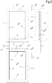
Figure 2 is a simplified top view of two adjacent sheets of a covering system according to a first embodiment of the invention, in which the support structure is not shown, and in which two bands of system coverage are shown; -
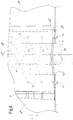
Figures 3 to 6 show a simplified top view of four adjacent sheets of a covering system according to a first embodiment of the invention, in which the support structure is not shown, and in which it is shown in sequence, the arrangement of the covering bands associated with said sheets; -
Figure 7 is a schematic axonometric view, in longitudinal section, or rather according to the slope direction of the covering, of a covering portion with two longitudinally adjacent sheets, according to the first embodiment of the invention; -
Figure 8 is a schematic axonometric view, in cross-section, or rather orthogonal to the slope direction of the roof, of a covering portion with two laterally adjacent sheets, according to the first embodiment of the invention; -
Figure 9 is a simplified top view of a covering portion relative to two adjacent sheets, on opposite sides, at the top of the covering of a covering system according to the first embodiment of the invention; -
Figure 10 is a schematic axonometric view, in cross-section, or rather orthogonal to the slope direction of the covering, of the covering portion ofFigure 9 ; -
Figure 11 is a schematic, axonometric view of a portion of a covering assembly with a supporting structure and a relative covering system, according to a second embodiment of the invention, in which a single sheet is visible and, separated from them, in exploded form, parts or portions of bands covering the spaces between adjacent sheets; -
Figure 12 is a schematic top view of a portion of covering compound according to the second embodiment of the invention, relative to nine structures and relative sheets as inFigure 11 , with the parts or portions of bands covering the spaces between adjacent sheets, arranged in a covering position; -
Figure 13 is a schematic top view of a portion of covering compound according to the second embodiment of the invention, relative to two adjacent sheets in the direction of the slope, with the only first covering band of the spaces between them highlighted; -
Figure 14 is a schematic top view of a portion of covering compound according to the second embodiment of the invention, relative to two laterally adjacent sheets with only the second covering band of the spaces between them shown ; -
Figure 15 is a schematic view, in longitudinal section, or rather according to the slope direction of the covering, of a covering portion with two longitudinally adjacent sheets, according to the second embodiment of the invention; -
Figure 15A is a schematic view, in longitudinal section, or rather according to the direction of slope of the covering, of a covering portion which is a variant comparing to the one ofFigure 15 ; -
Figure 16 is a schematic axonometric view, in cross-section, or rather orthogonal to the slope direction of the roof, of a covering portion with two laterally adjacent sheets or of the "ridge" configuration, according to the second embodiment of the invention; -
Figure 17 is a cross-sectional view ofconnecting means 21 between bands and sheets or between bands and bands in a system according to the invention, of the pin-type and eyelet locking hole, with a dotted highlighted pin locking position; -
Figure 18 is a plan view ofFigure 17 . - With reference to the aforementioned figures, a cover system is generally referred to as
number 10. - The covering
system 10 is associated with supporting structures formed for example by scaffolding equipped with support posts on the ground 11 (which can also be cantilevered by means of reticular structures) on whichframes 12, preferably quadrangular, and more preferably rectangular, are fixed .Frames 12 are made of elongated elements, such as 12T cross members and 12L side members. - For example, these frames are inclined to provide a sloping cover which therefore has a longitudinal portion of
ridge 13. Coveringsheets 14, preferably rectangular, are arranged inside the areas defined by theframes 12, and fixed to the same frames, as explained below. In practice, theframes 12 define support areas for thesheets 14. - For example, the covering
sheets 14 are arranged to cover an extended surface, for example an house roof in reconstruction, and are therefore impervious and arranged adjacent one to the other, above the roof, according to a matrix configuration.Figure 1 shows an example of a covering system configuration in which there are nine adjacent sheets, arranged according to a 3x3 matrix, inclined by the longitudinal portion ofridge 13 downwards. The direction of downward inclination or rather the slope is indicated by arrow Z. - It should be noted that the ground uprights 11 are not always necessary, in the sense that it is not strictly necessary that one or more uprights 11 are associated with a
frame 12. In fact, in most cases, theframes 12 are connected together to form a matrix, while the supports on the ground can be present, for example only in the sides relative to the ends of the matrix (for example, in the case of one single building to be covered, the uprights can be four, placed at the corners of the matrix, and however there are nine or more frames, so it is evident that many of these will be free of uprights but will be supported by adjacent frames). - Name with a, b, c the rows and columns of the matrix, with "a" at the top and left side of the matrix and "c" the lower and right part, the sheets are also indicated with an apex: 14aa indicates the first sheet close to the
ridge ridge 13, included between 14aa and 14ac. Likewise, 14ba indicates the sheet lowerly adjacent thesheet sheet 14ab and so on, also for row c. - The
sheets 14 preferably include, along their perimeter, close to the edge area, a plurality ofeyelets 15 to allow fixing to theframes 12 by means ofcables 16, hooks or the like, according to the prior art. - In practice, in this example, each side of a sheet is connected to the elongated member of the
nearest frame 12. Each side of asheet 14 is indicated with the number of the corresponding sheet (with relative quotes) followed by one of the letters i (lower), h (upper), d (right), s (left) which respectively indicate the position with reference to the orientation on the figures. Therefore 14abi indicates the lower side of thesheet sheet 14cb etc. - Moreover, two sides of two
sheets 14 adjacent to each other are fixed, on opposite sides, to anelongated element elongate element sheet 14ba and the 14bbh side of theadjacent sheet 14bb there is space occupied by a crosspiece 14T, to which the two sheets are connected bycables 16, passing through theeyelets 15 associated with said sides. - In other embodiments, the sheets may have dimensions that are integer multiples of the corresponding frame sizes, thus reducing the number of required eyelets and the assembly and disassembly time of the system.
- The covering system comprises
bands 17, which are also suitably waterproof, for covering the border areas between adjacent sheets. In particular, thesebands 17 are superimposed onto the edge areas of the sheets, or rather they overlap these edge areas, in correspondence with the boundary areas which they must cover. - More in particular, the
bands 17 also overlap theeyelets 15 present in the edge areas of both adjacent sheets that the bands connect. - According to a first embodiment of the invention, there are two
bands 17 for eachsheet 14, arranged on adjoining orthogonal sides, each one welded on the upper face of arelative sheet 14, parallel to a respective side thereof. In the following, the numbering of the bands follows the same logic of the numbering of the sides of the sheets. - For example, taking reference to the sheet 14ba (see
Figures 2 and7 ), there is afirst band 17bai welded (or glued or other technology which allows liquid tight seal, or a "waterproof seal) along a joiningstrip 18, to the upper face of the sheet, parallel to itslower side 14bai (defined hereinafter also as "first side"). Saidband 17bai has a width (or rather the dimension according to the direction z) such that it protrudes from to the edge of thelower side 14bai and overlap the edge area of the sheet adjacent below14ca. - It should be noted that the joining
strip 18 is made on thesheet 14ba in the opposite edge position of therespective side 14bai in relation to the series ofeyelets 15 made along saidside 14bai, so that theband 17bai overlaps the eyelets. - Each
band 17, in addition to the connecting strip to the respective sheet, also comprises reversible connecting means 21 to the respective adjacent sheet towards which the band protrudes. For example, these connectingmeans 21 comprise an upper connecting strip 22 provided on the lower face of the respective band and alower connection strip 23 provided on the upper face of the adjacent sheet, with the two connecting strips which are adapted to fix each other in a reversible way. For example, the two connecting strips are male-female strips of a Velcro-type fastening system, suitably of the liquid-tight type. Considering theband 17bai of theaforementioned sheet 14ba, this comprises, near its lower edge, an upper female (or male)velcro connection strip 22bai. On theadjacent sheet 14ca, in the edge area of theupper side 14cah, along this, there is a complementary lower connection male (or female)velcro strip 23cah. - It should be noted that the lower connection strip with male (or female)
velcro 23cah is made on theadjacent sheet 14ca in the opposite edge position of therespective side 14cah in relation to the series ofeyelets 15 made along saidside 14cah, therefore theband 17bai overlaps the eyelets on this side too. - In this way the
lower band 17bai overlaps all the downwardly openings present on and between the twoadjacent sheets eyelets 15 and the space between the lower and upper sides of the two sheets, close to theelongated element 12T. In the event of rain, the water slides along thesheet 14ba, passes over thelower band 17bai sliding on the loweradjacent sheet 14ca, overcoming the eyelets and the space between the sheets without slipping under the sheets. - The
second band 17 associated with thesheet 14 is placed along a second contiguous and orthogonal side to the first lower side to which the first described band is associated. It is in practice a side band that covers the eyelets and the intermediate space between two laterally adjacent sheets. - Always taking the 14ba sheet as an example (see
Figures 2 and8 ), thesecond band 17bad is welded (or glued or other technology which allows a liquid tight seal, or a "waterproof seal) along arespective union strip 18, to the upper face of the sheet, parallel to itsright side 14bad (defined hereinafter also as "second side"). Saidband 17bad has a width (or rather, the left-right side dimension referred to the figures) such that it protrudes from the edge of theright side 14bad and overlaps the edge area of the laterallyadjacent sheet 14bb. - It should be noted that the joining
strip 18 is made on thesheet 14ba in the opposite edge position of therespective side 14bad in relation to the series ofeyelets 15 made along thisside 14bad, so that theband 17bad overlaps the eyelets. - Similarly to the
first band 17bai, thesecond band 17bad, or rather the side band of thesheet 14ba comprises, near its right edge, a upper connection strip of female (or male)velcro 22bad. On the sideadjacent sheet 14bb, in the edge area of theleft side 14bbs, along this, there is a complementary lower connection male (or female)velcro strip 23bbs. - It should be noted that the lower connection male (or female)
velcro strip 23bbs is made on the laterallyadjacent sheet 14bb in the opposite edge position of therespective side 14bbs in relation to the series ofeyelets 15 made along saidside 14bbs, so that thelateral band 17bad overlaps the eyelets of this side too. - In this way the
side band 17bad overlaps all the openings to the right present on and between the twoadjacent sheets eyelets 15 and the space between the side edges of the two sheets, close to theelongated element 12L. In case of rain, the water slides along theside band 17bad and can slide indifferently towards thesheet 14ba or thesheet 14bb, without slipping under the sheets. - The first band (or lower band) and the second band (or side band) can be made separately or, in an advantageous form of embodiment, in a single "L" shaped band.
-
Figures 3 to 6 show an example of four adjacent sheets (according to a matrix arrangement 4x4 ba, bb, ca, cb), in which the overlapping of the sheets and their overlapping area are visible. - It should be noted that, preferably, the width of the bands, in the overlapping direction to the adjacent sheet, is such that the end edge of the band is downstream of the bottom connection male (or female)
Velcro strip 23 which connected to the adjacent sheet (or rather the upper female - or male - velcro strip 22 is not placed exactly on the edge of the band, but further upstream of this). - The
system 10 provides, for each sheet present on a first side close to theridge 13, a band welded also on the upper side of the sheet, (or rather a three-band configuration) such as to cover the space between the upper edges of the sheets along theridge 13. Each sheet present on the opposite side of the ridge has instead a configuration with two bands, as described above. -
Figures 9 and 10 show a cross section relative to theridge 13. Here is shown theridge crosspiece 12T which divides the support structure of the sheets into two slopes. On the left side of the ridge, in relation to the figure, thesheet 14ab is shown, with theside 14abh parallel to theridge 13 and spaced from it. On the right side of the ridge thesheet 14AB is shown, similar , for example, to thesheet 14ba described above. - This
ridge sheet 14ab advantageously comprises three coveringbands 17, a first lower band (not shown in these figures), which extends along the lower side of thesheet 14abi, to close the gap between thesheet 14ab and the edge of the adjacentlower sheet 14bb, asecond side band 17abd, which extends along a lateral side of the sheet, to close the gap between thesheet 14ab and the edge of theadjacent lateral sheet 17ac, and a thirdupper band 17abh which extends along theupper side 14abh of thesheet 14ab, to close the gap between theridge sheet 14ab and the edge of theadjacent sheet 14AB on the other side of the ridge itself. As for the previous cases, the thirdupper band 17abh is welded (or glued or other technology that allows a liquid tight seal, or a "waterproof seal) along aunion strip 18, to the upper face of the sheet, parallel to itsupper side 14abh. Thethird band 17abh has a width (or rather the dimension along the slant from bottom to top) such that it protrudes from theupper edge side 14abh and crosses the ridge and overlaps the edge area of theadjacent sheet 14AB on the other side of the ridge itself. - It should be noted that the joining
strip 18 is made on thesheet 14ab in the opposite edge position of therespective side 14abh in relation to the series ofeyelets 15 made along saidside 14abh, so that theband 17abh overlaps the eyelets. - Also in this case, the band-sheet connecting means 21 include, in proximity of the upper edge, a upper female (or male)
velcro connection strip 22abh. On theadjacent sheet 14AB, in the edge area of itsupper side 14ABh, along this, there is a complementary lower male (or female)velcro connection strip 23ABh. - It should be noted that the lower male (or female)
velcro connection strip 23ABh is made on theadjacent sheet 14AB in the opposite edge position of therespective side 14ABh in relation to the series ofeyelets 15 made along said side, so that theband 17abh overlaps the eyelets of this side too. - In this way the
upper band 17abh overlaps all the openings downwards present on and between the two adjacent ridge sheets onopposite sides eyelets 15 and the space between the upper sides of the two sheets, close to theelongated ridge element 12T. In case of rain, the water falls on theupper band 17abh and slides along thesheet -
Figures 17 and 18 show alternative connection means 21 in relation to the velcro. For example, the lower strip made on theadjacent sheet 14', suitable for connection with said upper strip, comprises eyelet holes 25, slotted, while the upper connection strip on theband 17 providespins 26 facing downwards (fixed with fluid seal to the band), suitable to be inserted into respective eyelet holes 25. Thepins 26 are equipped with ananti-slip portion 26A from these eyelet holes 25, movable in a reversible manner to assume an extraction configuration and an anti-slip configuration. In this example, theportion 26A has a complementary shape to the respective eyelet hole, or rather an elongated shape in one direction. Thisportion 26A rotates on an axis k coinciding with the insertion axis in the eyelets (or rather the axis of the pin), in order to be able to assume two configurations; a first configuration of insertion in the eyelet hole, in which the portion of the pin is rotated so as to be aligned with the development of the eyelet hole (to allow insertion), and a second configuration orthogonal to the first, with theportion 26A transversal to the development of the eyelet hole, which prevents the extraction movement of thepin 26 from theeyelet hole 25. - In some embodiments, in place of the welded zones (or glued or other irreversible liquid-tight connection form), connection regions may be present as shown in
Figures 17 and 18 and described above, with coupling between pins and eyelets holes of the liquid-tight type, for example for the presence of gaskets between pins and holes. -
Figures 11 to 16 show a preferred embodiment of the covering system according to the invention. - In this case, the covering system, globally indicated with 100, shows coverage bands for the spaces between the
sheets 14 which are composed of several elements, as explained below. Thesheets 14 are arranged inclined according to the slope Z, as in the previous example. In particular, there are two types of bands, afirst band 117 and asecond band 217. - The
first band 117 relates to the covering of the spaces between the sides of the orthogonal sheets to the direction of the slope Z, or rather those occupied by thecrosspieces 12T, while the type of thesecond band 217 relates to the covering of the spaces between the sides of the parallel sheets to the direction of the slope Z, or rather those occupied by thelongitudinal members 12L. -
Figure 12 shows nine sheets arranged in a matrix and numbered according to the previous example, and referring to the sheets of the columns "a" and "b", and the rows "b" and "c". - Taking the 14bb sheet as a reference, the
first band 117 is divided into three parts. - A
first part 117bbi is joined irreversibly, by means of its own joining strip 18 (for example welding or sealing with liquid tightness) along thelower side 14bbi of thesheet 14bb, made in an opposite edge position of the respectivelower side 14bbi in relation to the series ofeyelets 15 made along this side. - A
second part 117cbh is irreversibly joined, by means of its own joiningstrip 18, along theupper side 14cbh of thesheet 14cb lower adjacent to thesheet 14bb, made on thesheet 14cb in an opposite edge position of theside 14cbh on which it is joined in relation to the series ofeyelets 15 made along this side. - A
third part 117x ofband 117, has a rectangular shape and is a part released from the sheets before assembly, which is fixed to these by means ofconnection 121, visible inFigure 15 . In particular, such connection means allow connection of thisthird part 117x to thesecond part 117cbh (above that second part) and with the part of thesheet 14bb in a position underlying the first part of theband 117bbi, that is the part between theeyelets 15 and the joiningstrip 18 of thelower side 14bbi. - In this example, these connecting means are the same as those described above with reference to
figures 17 and 18 and the numbers relating to this example are indicated in parentheses. - In particular, this
third part 117x comprises, along its opposite sides, two parallel strips ofpins 126 facing downwards (fixed with liquid tightness to the third part of the band 117), adapted to be inserted in respective eyelet holes 125 made both along thesecond part 117cbh of thefirst band 117, and along the position below the first part of theband 117bbi, or rather, as said the part comprised between theeyelets 15 and the joiningstrip 18 of thelower side 14bbi. - Analogously to the example already described, the
pins 126 are provided with aportion 126A anti-slipping from these eyelet holes 125, movable in a reversible manner to assume a slip-off configuration and an anti-slip configuration. It should be noted that inFigure 5 , theanti-extraction portion 126A is rotated into a sealing position and can not be removed. - Therefore, the
first band 117 joins, with liquid tightness, in the direction of the slope, two adjacent sheets, preventing the water that slides on such sheets, to fall between the spaces around thecrosspieces 12L and relative to theeyelets 15. The first part of theband 117bbi, preferably free above the third part, prevents the water from infiltrating under the third part of theband 117x. - In an embodiment variant, shown in
Figure 15A , thefirst band 117 is subdivided into only two parts. - A
first part 117bbi is joined irreversibly, by means of its own joining strip 18 (for example welding or liquid-tight gluing) along thelower side 14bbi of thesheet 14bb, made in an opposite edge position of the respectivelower side 14bbi in relation to the series ofeyelets 15 made along this side. - A second part 117xk (which in practice is the combination of the second and third parts of the
band 117 described above), has a rectangular shape and is a part released from the sheets before assembly, which is fixed thereto by connectingmeans 121, visible inFigures 15 ,17 and 18 . In particular, these connecting means allow the connection of thissecond part 117xk with the part of thesheet 14bb in a position below thefirst part 117bbi, and with the part of thesheet 14cb along itsupper side 14cbh of thesheet 14cb, in an opposite edge position of theside 14cbh on which it is joined in relation to the series ofeyelets 15 made along this side. - For example, the connection means 121 are the pins and the eyelet holes described above, which however have a liquid tight coupling, for example due to the presence of gaskets between pins and holes.
- The
second band 217 can also be divided into three portions (see in particularFigure 14 ). Afirst portion 217bbd is joined in an irreversible manner, by means of its own joining strip 18 (for example welding or liquid-tight gluing) along theside 14bbd of thesheet 14bb, made in an opposite edge position of therespective side 14bb with respect to series ofeyelets 15 made along this side. - A
second portion 217bcs is irreversibly connected, by means of its own joiningstrip 18, along the side 14bcS of thesheet 14bc laterally adjacent to thesheet 14bb, made on thesheet 14bc in an opposite edge position of the side 14bcS on which it is joined to the series ofeyelets 15 made along this side. - A third portion of
band 217x, has a rectangular shape and is a portion released from the sheets before assembly, which is fixed to these by means of the same connection means 121 described above. In particular, said connecting means allow the connection of suchthird portion 217x with thesecond portion 217bc and with thefirst portion 217bbd, with the third portion which is arranged above them. - In particular, this
third portion 217x comprises (seeFigure 16 ), along its opposite sides, two parallel strips ofpins 126 facing downward (fixed with liquids seal to the third portion of the band 217), adapted to be inserted into respective eyelet holes 125 made both along the second portion 217bcS of thesecond band 217, and along the first portion ofband 217bbd. - All the
third parties 117x orportions 217x are connected to the sheets on their respective long side and to each other in contiguity on the short side. - It should be noted that the sheet 14bb (as well as all the other sheets adjacent thereto) of this second embodiment, advantageously presents four rectangular flaps, of the same material of the sheet, welded along the four sides; the flap along the
lower side 14bbi corresponds to the first part ofband 117bbi of afirst band 117x placed lowerly, the flap along theupper side 14bbh corresponds to thesecond part 117abh of afirst band 117x placed above. The flaps along the lateral edges of thesheet 14bb correspond respectively to the first portion ofband 217bbd and to a second portion ofband 217bbs for the connection to corresponding oppositesecond side bands 217x. - It should be noted that in this second embodiment, there are no special sheets relative to the
ridge 13, since the covering of the ridge zone is left to thefirst band 117x, which connects the upper sides of two adjacent sheets from opposite sides of the ridge . - It is understood that what is illustrated represents only possible non-limiting embodiments of the invention, which may vary in the forms and arrangements without departing from the scope of the concept underlying the invention. The presence of reference numbers in the appended claims has the sole purpose of facilitating reading thereof in the light of the foregoing description and of the attached drawings and does not in any way limit the scope of protection.
Claims (12)
- Modular covering system (10), to associate with one or more loadbearing structures (11,12), comprising- a plurality of covering sheets (14) quadrangular in shape, adapted to be arranged adjacent to one another and at least partially according to a matrix arrangement,- flexibles bands (17) for covering the border areas between adjacent sheets, arranged to overlap the edge areas of said sheets in the border areas they must cover,- connection means (21) of said bands with the respective sheets, said connection means being adapted to provide a reversible connection with at least one of said sheets,wherein said sheets comprise, along their perimeter, close to the edge area, a plurality of eyelets (15) for fixing to the supporting structures with which they are associated, by means of cables (16), hooks or the like; said covering bands (17) being arranged to overlap said eyelets,
wherein a sheet (14ba) comprises a first side (14bai) along which, parallel thereto, there is joined, by means of a joining strip (18) thereof, a said band (17bai), said band being arranged on the upper face of said sheet and protruding with respect to the edge of said first side to be able to overlap a sheet (14ca) arranged adjacent to said first side; said band comprising reversible connection means (21) to said adjacent sheet, said reversible connection means comprising an upper connection strip (22) provided on said band and a lower strip (23) produced on said adjacent sheet, adapted for connection with said upper strip, characterized in that said sheet comprises a second side (14bad), contiguous to said first side (14bai), along which, parallel thereto, there is joined, by means of a joining strip (18) thereof, a second said band (17bad), said second band being arranged on the upper face of said sheet and protruding with respect to the edge of said second side to be able to overlap a sheet (14bb) arranged adjacent to said second side; said second band comprising reversible connection means to said adjacent sheet, said reversible connection means comprising an upper connection strip (22bad) provided on said second band and a lower strip (23bbs) produced on said adjacent sheet, adapted for connection with said upper strip. - Modular covering system according to claim 1, wherein said first and said second band form a single band, preferably with a shape similar to an "L".
- Modular covering system according to claim 1 or 2, wherein said joining strip (18), preferably made by gluing or welding, is produced on said sheet in a position opposite the edge of the respective side with respect to the series of eyelets (15) produced along said respective side.
- Modular covering system according to any one of the preceding claims, wherein said upper connection strip provided on said band and said lower strip produced on said adjacent sheet, adapted for connection with said upper strip, comprise male-female elements of hook and loop type, preferably of waterproof type.
- Modular covering system according to anyone of claims 1 to 3, wherein said lower strip produced on said adjacent sheet (14'), adapted for connection with said upper strip, comprises holes with eyelets (25), while said upper connection strip provided on said band is provided with pins (26) facing downwards, adapted to be inserted into respective said holes with eyelets, said pins being provided with a portion (26A) to prevent removal from said holes with eyelets, movable reversibly to a configuration that allows removal and to a configuration that prevents removal.
- Modular covering system according to any one of the preceding claims, wherein said sheet is adapted to be arranged sloping and said first side (14bai) is at a lower height with respect to the opposite side of the sheet, so that said band (17bai) that is joined, with waterproof seal, to said sheet and that extends along said first side, overlaps the edge area of the upper side of the adjacent sheet (14ca), so that any water running on said sheet runs over said band without penetrating between band and sheet and therefore continues to run on said adjacent sheet.
- Modular covering system according to claim 6, comprising a said sheet (14ab) adapted to occupy the position close to the ridge (13) of the covering, said ridge sheet being sloping and having an upper side (14abh) adjacent to an elongated element (12T) of the supporting structure that defines the ridge of the covering system; said sheet comprising a third upper band (17abh) that extends along the upper side (14abh) of the sheet, for covering the space between the sheet and the edge of the adjacent sheet (14AB) on the other part of the ridge of the covering system.
- Modular covering system according to any one of the preceding claims, wherein at least a first of said bands (117) is divided into three portions:- a first portion (117bbi) joined irreversibly, by means of its joining strip, along said side of said respective sheet (14bb); preferably said joining strip being produced on said respective sheet in a position opposite the edge of the respective side with respect to the series of eyelets (125) produced along said respective side;- a second portion (117cbh) joined irreversibly, by means of its joining strip, along a side of a sheet (14cb) adjacent to said respective sheet; preferably said joining strip being produced on said adjacent sheet in a position opposite the edge of the side on which it is joined with respect to the series of eyelets produced along this side of adjacent sheet;- a third portion (117x) provided with said connection means with said second part and with said respective sheet in a position below said first part of band.
- Modular covering system according to any one of claims 1 to 7, wherein at least a first of said bands (117) is divided into two portions:- a first portion (117bbi) joined irreversibly, by means of its own joining strip, along said side of the respective sheet (14bb); preferably said joining strip being produced on said respective sheet in a position opposite the edge of the respective side with respect to the series of eyelets (125) produced along said respective side;- a second portion (117xk) provided with said connection means with a sheet (14cb) adjacent to said respective sheet and with said respective sheet in a position below said first part of band.
- Modular covering system according to claim 8 or 9, wherein at least a second (217) of said bands is divided into three portions:- a first portion (217bcS) joined irreversibly, by means of its joining strip, along said side of said respective sheet (14bc); preferably said joining strip being produced on said respective sheet in a position opposite the edge of the respective side with respect to the series of eyelets produced along said respective side;- a second portion (217bbd) joined irreversibly, by means of a joining strip thereof, along a side of a sheet (14bb) adjacent to said respective sheet; preferably said joining strip being produced on said adjacent sheet in a position opposite the edge of the side on which it is joined with respect to the series of eyelets produced along this side of adjacent sheet;- a third portion (217x) provided with said connection means with said first and said second portion, preferably in a position above said first and second portion.
- Modular covering system according to any one of the preceding claims, wherein said connection means of said bands with the respective sheets comprise, for each band, at least a connection strip that comprises pins (126) facing downwards, adapted to be inserted into respective holes with eyelets (125) produced on portions of said band integral with said sheet, or on said sheet; said pins being provided with a portion (126A) to prevent removal from said holes with eyelets, movable reversibly to a configuration that allows removal and to a configuration that prevents removal.
- Covering assembly comprising a modular covering system according to one or more of the preceding claims and a supporting structure for said sheets, with said sheets arranged adjacent to one another; preferably, said supporting structures defining supporting areas inside which respective sheets are arranged; preferably said supporting structures comprise a plurality of frames defining said areas inside which respective sheets are arranged; said frames comprising elongated elements; said elongated elements and said eyelets being connected by said cables, hooks or the like for supporting said sheets.
Applications Claiming Priority (1)
| Application Number | Priority Date | Filing Date | Title |
|---|---|---|---|
| IT102016000132413A IT201600132413A1 (en) | 2016-12-29 | 2016-12-29 | MODULAR COVERAGE SYSTEM |
Publications (3)
| Publication Number | Publication Date |
|---|---|
| EP3342958A1 true EP3342958A1 (en) | 2018-07-04 |
| EP3342958C0 EP3342958C0 (en) | 2024-11-20 |
| EP3342958B1 EP3342958B1 (en) | 2024-11-20 |
Family
ID=58671773
Family Applications (1)
| Application Number | Title | Priority Date | Filing Date |
|---|---|---|---|
| EP17211234.4A Active EP3342958B1 (en) | 2016-12-29 | 2017-12-29 | Modular covering system |
Country Status (2)
| Country | Link |
|---|---|
| EP (1) | EP3342958B1 (en) |
| IT (1) | IT201600132413A1 (en) |
Cited By (1)
| Publication number | Priority date | Publication date | Assignee | Title |
|---|---|---|---|---|
| JP7123440B1 (en) | 2021-06-30 | 2022-08-23 | 株式会社サトウ塗工社 | seat |
Citations (6)
| Publication number | Priority date | Publication date | Assignee | Title |
|---|---|---|---|---|
| FR2393993A1 (en) * | 1977-06-07 | 1979-01-05 | Caron Claude | Large area waterproof membrane for liquid storage points - is tested for leakage at each joint by sealant |
| JP3016072B2 (en) * | 1997-02-18 | 2000-03-06 | 政太郎 佐藤 | Sheet curtain |
| JP3205661B2 (en) * | 1994-03-23 | 2001-09-04 | 太陽工業株式会社 | Seat link |
| JP2003097051A (en) * | 2001-09-26 | 2003-04-03 | Kosuke Nakakoshi | Waterproof sheet with pouch |
| JP2006089987A (en) * | 2004-09-22 | 2006-04-06 | Kanemasa Kogyo Kk | Curing sheet set for temporary structure built for disposal of toxic substance generating facilities, including dismantling of incinerator, and temporary structure on which the curing sheet set is placed |
| CA2540994A1 (en) * | 2006-03-21 | 2007-09-21 | Dragomir Smoljo (Doug) | Enclosure system for scaffolding |
-
2016
- 2016-12-29 IT IT102016000132413A patent/IT201600132413A1/en unknown
-
2017
- 2017-12-29 EP EP17211234.4A patent/EP3342958B1/en active Active
Patent Citations (6)
| Publication number | Priority date | Publication date | Assignee | Title |
|---|---|---|---|---|
| FR2393993A1 (en) * | 1977-06-07 | 1979-01-05 | Caron Claude | Large area waterproof membrane for liquid storage points - is tested for leakage at each joint by sealant |
| JP3205661B2 (en) * | 1994-03-23 | 2001-09-04 | 太陽工業株式会社 | Seat link |
| JP3016072B2 (en) * | 1997-02-18 | 2000-03-06 | 政太郎 佐藤 | Sheet curtain |
| JP2003097051A (en) * | 2001-09-26 | 2003-04-03 | Kosuke Nakakoshi | Waterproof sheet with pouch |
| JP2006089987A (en) * | 2004-09-22 | 2006-04-06 | Kanemasa Kogyo Kk | Curing sheet set for temporary structure built for disposal of toxic substance generating facilities, including dismantling of incinerator, and temporary structure on which the curing sheet set is placed |
| CA2540994A1 (en) * | 2006-03-21 | 2007-09-21 | Dragomir Smoljo (Doug) | Enclosure system for scaffolding |
Cited By (2)
| Publication number | Priority date | Publication date | Assignee | Title |
|---|---|---|---|---|
| JP7123440B1 (en) | 2021-06-30 | 2022-08-23 | 株式会社サトウ塗工社 | seat |
| JP2023006335A (en) * | 2021-06-30 | 2023-01-18 | 株式会社サトウ塗工社 | sheet |
Also Published As
| Publication number | Publication date |
|---|---|
| EP3342958C0 (en) | 2024-11-20 |
| IT201600132413A1 (en) | 2018-06-29 |
| EP3342958B1 (en) | 2024-11-20 |
Similar Documents
| Publication | Publication Date | Title |
|---|---|---|
| US5421355A (en) | Tent assembly having multiple configurations | |
| US3862532A (en) | Roof tile | |
| US3805816A (en) | Protective covering | |
| CN102046002B (en) | Crop cover | |
| US3415027A (en) | Truss of spaced pyramidal units | |
| USRE37498E1 (en) | Automotive hail protection and shade canopy | |
| US10272971B2 (en) | Watercraft canopy for U-shaped dock | |
| US3934277A (en) | Portable swimming pool construction | |
| EP3342958B1 (en) | Modular covering system | |
| US8959854B1 (en) | Weatherproof fabric-covered building system | |
| US2814999A (en) | Metal roof or wall construction | |
| US20020134415A1 (en) | Modular tent | |
| FI116374B (en) | Ship | |
| US11434657B1 (en) | Protective cover for frame tent fittings | |
| KR101995474B1 (en) | Assembly tent with internal envelops | |
| US3855753A (en) | Tile and tile roofing | |
| CA3024239C (en) | Watercraft canopy for u-shaped dock | |
| US715185A (en) | Brick-drying shed. | |
| KR200346359Y1 (en) | Boat with tent | |
| US3122152A (en) | Transportable and convertible shelter | |
| KR102876756B1 (en) | A Double Air Pole Type of a Shelter Capable of Being Used as a Tent | |
| GB2177436A (en) | Gazebo | |
| RU2617767C1 (en) | Device for joint connection of flexible materials | |
| KR102903012B1 (en) | Assembly type flower bed | |
| CN223867742U (en) | A type of air column outdoor tent that facilitates ventilation |
Legal Events
| Date | Code | Title | Description |
|---|---|---|---|
| PUAI | Public reference made under article 153(3) epc to a published international application that has entered the european phase |
Free format text: ORIGINAL CODE: 0009012 |
|
| STAA | Information on the status of an ep patent application or granted ep patent |
Free format text: STATUS: THE APPLICATION HAS BEEN PUBLISHED |
|
| AK | Designated contracting states |
Kind code of ref document: A1 Designated state(s): AL AT BE BG CH CY CZ DE DK EE ES FI FR GB GR HR HU IE IS IT LI LT LU LV MC MK MT NL NO PL PT RO RS SE SI SK SM TR |
|
| AX | Request for extension of the european patent |
Extension state: BA ME |
|
| STAA | Information on the status of an ep patent application or granted ep patent |
Free format text: STATUS: REQUEST FOR EXAMINATION WAS MADE |
|
| 17P | Request for examination filed |
Effective date: 20181228 |
|
| RBV | Designated contracting states (corrected) |
Designated state(s): AL AT BE BG CH CY CZ DE DK EE ES FI FR GB GR HR HU IE IS IT LI LT LU LV MC MK MT NL NO PL PT RO RS SE SI SK SM TR |
|
| STAA | Information on the status of an ep patent application or granted ep patent |
Free format text: STATUS: EXAMINATION IS IN PROGRESS |
|
| 17Q | First examination report despatched |
Effective date: 20200921 |
|
| GRAP | Despatch of communication of intention to grant a patent |
Free format text: ORIGINAL CODE: EPIDOSNIGR1 |
|
| GRAP | Despatch of communication of intention to grant a patent |
Free format text: ORIGINAL CODE: EPIDOSNIGR1 |
|
| STAA | Information on the status of an ep patent application or granted ep patent |
Free format text: STATUS: GRANT OF PATENT IS INTENDED |
|
| RIC1 | Information provided on ipc code assigned before grant |
Ipc: E04G 21/24 20060101ALN20240524BHEP Ipc: E04H 15/54 20060101ALI20240524BHEP Ipc: E04G 21/28 20060101AFI20240524BHEP |
|
| INTG | Intention to grant announced |
Effective date: 20240614 |
|
| RIC1 | Information provided on ipc code assigned before grant |
Ipc: E04G 21/24 20060101ALN20240604BHEP Ipc: E04H 15/54 20060101ALI20240604BHEP Ipc: E04G 21/28 20060101AFI20240604BHEP |
|
| GRAS | Grant fee paid |
Free format text: ORIGINAL CODE: EPIDOSNIGR3 |
|
| GRAA | (expected) grant |
Free format text: ORIGINAL CODE: 0009210 |
|
| STAA | Information on the status of an ep patent application or granted ep patent |
Free format text: STATUS: THE PATENT HAS BEEN GRANTED |
|
| AK | Designated contracting states |
Kind code of ref document: B1 Designated state(s): AL AT BE BG CH CY CZ DE DK EE ES FI FR GB GR HR HU IE IS IT LI LT LU LV MC MK MT NL NO PL PT RO RS SE SI SK SM TR |
|
| REG | Reference to a national code |
Ref country code: GB Ref legal event code: FG4D |
|
| REG | Reference to a national code |
Ref country code: CH Ref legal event code: EP |
|
| REG | Reference to a national code |
Ref country code: DE Ref legal event code: R096 Ref document number: 602017086209 Country of ref document: DE |
|
| REG | Reference to a national code |
Ref country code: IE Ref legal event code: FG4D |
|
| U01 | Request for unitary effect filed |
Effective date: 20241220 |
|
| U07 | Unitary effect registered |
Designated state(s): AT BE BG DE DK EE FI FR IT LT LU LV MT NL PT RO SE SI Effective date: 20250110 |
|
| U20 | Renewal fee for the european patent with unitary effect paid |
Year of fee payment: 8 Effective date: 20250114 |
|
| PG25 | Lapsed in a contracting state [announced via postgrant information from national office to epo] |
Ref country code: IS Free format text: LAPSE BECAUSE OF FAILURE TO SUBMIT A TRANSLATION OF THE DESCRIPTION OR TO PAY THE FEE WITHIN THE PRESCRIBED TIME-LIMIT Effective date: 20250320 Ref country code: HR Free format text: LAPSE BECAUSE OF FAILURE TO SUBMIT A TRANSLATION OF THE DESCRIPTION OR TO PAY THE FEE WITHIN THE PRESCRIBED TIME-LIMIT Effective date: 20241120 |
|
| PG25 | Lapsed in a contracting state [announced via postgrant information from national office to epo] |
Ref country code: ES Free format text: LAPSE BECAUSE OF FAILURE TO SUBMIT A TRANSLATION OF THE DESCRIPTION OR TO PAY THE FEE WITHIN THE PRESCRIBED TIME-LIMIT Effective date: 20241120 |
|
| PG25 | Lapsed in a contracting state [announced via postgrant information from national office to epo] |
Ref country code: NO Free format text: LAPSE BECAUSE OF FAILURE TO SUBMIT A TRANSLATION OF THE DESCRIPTION OR TO PAY THE FEE WITHIN THE PRESCRIBED TIME-LIMIT Effective date: 20250220 |
|
| PG25 | Lapsed in a contracting state [announced via postgrant information from national office to epo] |
Ref country code: GR Free format text: LAPSE BECAUSE OF FAILURE TO SUBMIT A TRANSLATION OF THE DESCRIPTION OR TO PAY THE FEE WITHIN THE PRESCRIBED TIME-LIMIT Effective date: 20250221 |
|
| PGFP | Annual fee paid to national office [announced via postgrant information from national office to epo] |
Ref country code: CH Payment date: 20250122 Year of fee payment: 8 |
|
| PG25 | Lapsed in a contracting state [announced via postgrant information from national office to epo] |
Ref country code: PL Free format text: LAPSE BECAUSE OF FAILURE TO SUBMIT A TRANSLATION OF THE DESCRIPTION OR TO PAY THE FEE WITHIN THE PRESCRIBED TIME-LIMIT Effective date: 20241120 |
|
| PG25 | Lapsed in a contracting state [announced via postgrant information from national office to epo] |
Ref country code: RS Free format text: LAPSE BECAUSE OF FAILURE TO SUBMIT A TRANSLATION OF THE DESCRIPTION OR TO PAY THE FEE WITHIN THE PRESCRIBED TIME-LIMIT Effective date: 20250220 |
|
| PG25 | Lapsed in a contracting state [announced via postgrant information from national office to epo] |
Ref country code: SM Free format text: LAPSE BECAUSE OF FAILURE TO SUBMIT A TRANSLATION OF THE DESCRIPTION OR TO PAY THE FEE WITHIN THE PRESCRIBED TIME-LIMIT Effective date: 20241120 |
|
| PG25 | Lapsed in a contracting state [announced via postgrant information from national office to epo] |
Ref country code: SK Free format text: LAPSE BECAUSE OF FAILURE TO SUBMIT A TRANSLATION OF THE DESCRIPTION OR TO PAY THE FEE WITHIN THE PRESCRIBED TIME-LIMIT Effective date: 20241120 |
|
| PG25 | Lapsed in a contracting state [announced via postgrant information from national office to epo] |
Ref country code: CZ Free format text: LAPSE BECAUSE OF FAILURE TO SUBMIT A TRANSLATION OF THE DESCRIPTION OR TO PAY THE FEE WITHIN THE PRESCRIBED TIME-LIMIT Effective date: 20241120 |
|
| PG25 | Lapsed in a contracting state [announced via postgrant information from national office to epo] |
Ref country code: MC Free format text: LAPSE BECAUSE OF FAILURE TO SUBMIT A TRANSLATION OF THE DESCRIPTION OR TO PAY THE FEE WITHIN THE PRESCRIBED TIME-LIMIT Effective date: 20241120 |
|
| PLBE | No opposition filed within time limit |
Free format text: ORIGINAL CODE: 0009261 |
|
| STAA | Information on the status of an ep patent application or granted ep patent |
Free format text: STATUS: NO OPPOSITION FILED WITHIN TIME LIMIT |
|
| 26N | No opposition filed |
Effective date: 20250821 |
|
| PG25 | Lapsed in a contracting state [announced via postgrant information from national office to epo] |
Ref country code: IE Free format text: LAPSE BECAUSE OF NON-PAYMENT OF DUE FEES Effective date: 20241229 |
|
| U20 | Renewal fee for the european patent with unitary effect paid |
Year of fee payment: 9 Effective date: 20251224 |
|
| PGFP | Annual fee paid to national office [announced via postgrant information from national office to epo] |
Ref country code: GB Payment date: 20260227 Year of fee payment: 9 |