EP3342916A1 - Washing machine - Google Patents
Washing machine Download PDFInfo
- Publication number
- EP3342916A1 EP3342916A1 EP16838584.7A EP16838584A EP3342916A1 EP 3342916 A1 EP3342916 A1 EP 3342916A1 EP 16838584 A EP16838584 A EP 16838584A EP 3342916 A1 EP3342916 A1 EP 3342916A1
- Authority
- EP
- European Patent Office
- Prior art keywords
- supporting
- supporting member
- washing
- drum
- washing drum
- Prior art date
- Legal status (The legal status is an assumption and is not a legal conclusion. Google has not performed a legal analysis and makes no representation as to the accuracy of the status listed.)
- Granted
Links
- 238000005406 washing Methods 0.000 title claims abstract description 166
- 238000009434 installation Methods 0.000 abstract description 6
- 238000010586 diagram Methods 0.000 description 10
- 238000005452 bending Methods 0.000 description 9
- 239000002184 metal Substances 0.000 description 9
- 229910052751 metal Inorganic materials 0.000 description 9
- 238000001035 drying Methods 0.000 description 8
- 230000000149 penetrating effect Effects 0.000 description 8
- 238000000034 method Methods 0.000 description 5
- XLYOFNOQVPJJNP-UHFFFAOYSA-N water Substances O XLYOFNOQVPJJNP-UHFFFAOYSA-N 0.000 description 5
- 230000003287 optical effect Effects 0.000 description 3
- 241000276425 Xiphophorus maculatus Species 0.000 description 2
- 229920001971 elastomer Polymers 0.000 description 2
- 239000011347 resin Substances 0.000 description 2
- 229920005989 resin Polymers 0.000 description 2
- 210000000078 claw Anatomy 0.000 description 1
- 230000003247 decreasing effect Effects 0.000 description 1
- 238000001514 detection method Methods 0.000 description 1
- 230000000694 effects Effects 0.000 description 1
- 239000000806 elastomer Substances 0.000 description 1
Images




Classifications
-
- D—TEXTILES; PAPER
- D06—TREATMENT OF TEXTILES OR THE LIKE; LAUNDERING; FLEXIBLE MATERIALS NOT OTHERWISE PROVIDED FOR
- D06F—LAUNDERING, DRYING, IRONING, PRESSING OR FOLDING TEXTILE ARTICLES
- D06F37/00—Details specific to washing machines covered by groups D06F21/00 - D06F25/00
- D06F37/20—Mountings, e.g. resilient mountings, for the rotary receptacle, motor, tub or casing; Preventing or damping vibrations
- D06F37/22—Mountings, e.g. resilient mountings, for the rotary receptacle, motor, tub or casing; Preventing or damping vibrations in machines with a receptacle rotating or oscillating about a horizontal axis
-
- D—TEXTILES; PAPER
- D06—TREATMENT OF TEXTILES OR THE LIKE; LAUNDERING; FLEXIBLE MATERIALS NOT OTHERWISE PROVIDED FOR
- D06F—LAUNDERING, DRYING, IRONING, PRESSING OR FOLDING TEXTILE ARTICLES
- D06F37/00—Details specific to washing machines covered by groups D06F21/00 - D06F25/00
- D06F37/20—Mountings, e.g. resilient mountings, for the rotary receptacle, motor, tub or casing; Preventing or damping vibrations
-
- D—TEXTILES; PAPER
- D06—TREATMENT OF TEXTILES OR THE LIKE; LAUNDERING; FLEXIBLE MATERIALS NOT OTHERWISE PROVIDED FOR
- D06F—LAUNDERING, DRYING, IRONING, PRESSING OR FOLDING TEXTILE ARTICLES
- D06F37/00—Details specific to washing machines covered by groups D06F21/00 - D06F25/00
- D06F37/26—Casings; Tubs
- D06F37/264—Tubs provided with reinforcing structures, e.g. ribs, inserts, braces
-
- D—TEXTILES; PAPER
- D06—TREATMENT OF TEXTILES OR THE LIKE; LAUNDERING; FLEXIBLE MATERIALS NOT OTHERWISE PROVIDED FOR
- D06F—LAUNDERING, DRYING, IRONING, PRESSING OR FOLDING TEXTILE ARTICLES
- D06F37/00—Details specific to washing machines covered by groups D06F21/00 - D06F25/00
- D06F37/30—Driving arrangements
- D06F37/40—Driving arrangements for driving the receptacle and an agitator or impeller, e.g. alternatively
-
- D—TEXTILES; PAPER
- D06—TREATMENT OF TEXTILES OR THE LIKE; LAUNDERING; FLEXIBLE MATERIALS NOT OTHERWISE PROVIDED FOR
- D06F—LAUNDERING, DRYING, IRONING, PRESSING OR FOLDING TEXTILE ARTICLES
- D06F49/00—Domestic spin-dryers or similar spin-dryers not suitable for industrial use
- D06F49/06—Mountings, e.g. resilient mountings, for the bowl or casings; Preventing or damping vibrations
-
- D—TEXTILES; PAPER
- D06—TREATMENT OF TEXTILES OR THE LIKE; LAUNDERING; FLEXIBLE MATERIALS NOT OTHERWISE PROVIDED FOR
- D06F—LAUNDERING, DRYING, IRONING, PRESSING OR FOLDING TEXTILE ARTICLES
- D06F23/00—Washing machines with receptacles, e.g. perforated, having a rotary movement, e.g. oscillatory movement, the receptacle serving both for washing and for centrifugally separating water from the laundry
- D06F23/06—Washing machines with receptacles, e.g. perforated, having a rotary movement, e.g. oscillatory movement, the receptacle serving both for washing and for centrifugally separating water from the laundry and rotating or oscillating about an inclined axis
Definitions
- the present invention relates to a washing machine.
- an outer drum part assembled with a rotating drum part with washings thrown therein is supported by a rotation supporting member through an inclined rotation supporting shaft.
- a pair of rotation supporting members is arranged in a manner of sandwiching the outer drum part, and each rotation supporting member is supported by an outer frame of the washing and drying machine through a hoisting rod.
- the outer drum part is provided with a rotation operating rope installing part, and an operating rope connected to the rotation operating rope installing part is coiled on a drum arranged on an inclined rotation motor of the outer frame.
- the inclined rotation motor rotates, the operating rope moves upwards or downwards.
- the outer drum part obliquely rotates around the inclined rotation supporting shaft.
- the outer drum part is transversely inclined when the washings are thrown into the rotating drum part, and the outer drum part is disposed along a perpendicular direction during washing, rinse and dewatering.
- a part for mounting a hoisting rod of each rotation supporting member is located on an outer side surface of the rotation supporting member opposite to the outer drum part side.
- the hoisting rod is configured in a manner of extending to the outer side of the rotation supporting member and may cause the washing and drying machine to become larger, it is difficult to reduce the space occupied by the washing and drying machine.
- rigidity of the rotation supporting member which rotatably supports the outer drum part is expected to be increased.
- Patent Literature 1 Japanese Laid-open patent publication No. 4-166196
- the present invention is based on the background, and aims to provide a washing machine which can save an installation space and can increase rigidity of a part for rotatably supporting a washing drum in a structure including the washing drum, where the washing drum can rotate in a manner of crossing with a perpendicular direction.
- the present invention provides a washing machine, including: a washing drum accommodating washings and rotating in a manner of crossing with a perpendicular direction; a supporting member arranged on an outer side of the washing drum and rotatably supporting the washing drum; a bent part arranged on the supporting members and bent towards a side of the washing drum; and an elastic supporting member mounted on the bent part and elastically supporting the supporting member.
- the washing machine includes a driving mechanism arranged between the supporting member and the washing drum and rotating the washing drum.
- the driving mechanism includes a base part formed in a locally bent manner and mounted on the supporting member.
- the washing machine is sandwiched between a pair of the supporting members; and the washing machine includes a beam member arranged between the pair of the supporting members.
- the washing machine is sandwiched between a pair of the supporting members;
- the washing machine includes a supporting frame which is an integral supporting frame integrally having the pair of the supporting members; and a bottom member arranged between lower ends of the pair of the supporting members.
- the washing drum in the washing machine including the washing drum, the supporting member arranged on the outer side of the washing drum rotatably supports the washing drum, the washing drum can rotate in a manner of crossing with a perpendicular direction.
- the bent part which is bent towards the washing drum, is arranged on the supporting member.
- rigidity of the supporting member can be increased.
- the elastic supporting member for elastically supporting the supporting member is mounted on the bent part.
- the elastic supporting member since the elastic supporting member is arranged on the side where the washing drum is (i.e., the inner side of the supporting member) rather than in a manner of extending to a side of the supporting member opposite to the washing drum (i.e., an outer side), the washing machine can become smaller. Thus, an installation space of the washing machine can be reduced.
- the washing machine since the driving mechanism for rotating the washing drum is not arranged between the supporting member and the washing drum rather than in a manner of extending to the outer side of the supporting member, the washing machine can become smaller. Thus, an installation space of the washing machine can be reduced.
- the base part, mounted on the supporting member, of the driving mechanism is formed in a locally bent manner, so that the rigidity can be increased.
- the supporting member is strengthened through the base part, the rigidity of the supporting members can be further increased.
- the beam member is arranged between a pair of the supporting members, which are arranged in a manner of sandwiching the washing drum.
- the rigidity of the supporting members can be further increased.
- a pair of the supporting members arranged in a manner of sandwiching the washing drum and the bottom member arranged between the lower ends of the pair of the supporting members are integrated to form the integral supporting frame, so that the rigidity of the supporting members can be further increased.
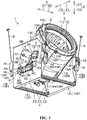
- Fig. 1 is a schematic three-dimensional diagram illustrating a washing machine 1 in an embodiment of the present invention.
- An up-down direction in Fig. 1 is called as an up-down direction Z of the washing machine 1;
- a left-right direction in Fig. 1 is called as a front-rear direction Y of the washing machine 1; and
- a transverse direction substantially orthogonal to paper of Fig. 1 is called as a left-right direction X.
- the up-down direction Z is also a perpendicular direction.
- an upper side is called as an upper side Z1; and a lower side is called as a lower side Z2.
- a right side in Fig. 1 is called as a front side Y1; and a left side in Fig. 1 is called as a rear side Y2.
- a left side in Fig. 1 is called as a rear side Y2.
- an outer side of the paper of Fig. 1 is called as a left side X1; and an inner side of the paper of Fig. 1 is called as a right side X2.
- the washing machine 1 although the washing machine 1 also includes a washing and drying machine with a clothes drying function, the washing machine 1 hereafter, which only executes washing operation without explaining the clothes drying function, is taken as an example.
- the washing operation includes a washing process, a rinsing process and a dewatering process.
- the washing machine 1 includes: a housing 2, a washing drum 3 arranged in the housing 2, a supporting frame 4, an elastic supporting member 5, a rotating part 6, an unlocking mechanism 7 and a driving mechanism 8.
- the housing 2 is, for example, made of metal, and is formed in a shape of a box.
- a connecting surface 2C for connecting a front surface 2A and an upper surface 2B is arranged on the housing 2.
- the connecting surface 2C is, for example, an inclined surface which drops towards the front side Y1.
- An outlet-inlet (not shown) for throwing in and taking out washings from the washing machine 1 is formed in a manner of bridging the front surface 2A and the connecting surface 2C.
- the washing drum 3 includes an outer drum 10 and an inner drum 11.
- the outer drum 10 is, for example, made of resin, and is formed in a cylindrical shape with a bottom.
- An imaginary straight line passing through a center of a circle of the outer drum 10 is a central axis J of the outer drum 10.
- a circular opening 10A through which the washings are thrown in and taken out from the washing machine 1 is formed on an upper end of the outer drum 10 on an opposite side of a bottom wall (not shown).
- Metal rotating shafts 12 protruding to an outer side of the left-right direction X are arranged one by one on left and right side surfaces of the outer drum 10.
- Fig. 1 only shows the rotating shaft 12 on the left side X1.
- the pair of left and right rotating shafts 12 are disposed in a same position when observed from the left-right direction X.
- the inner drum 11 is, for example, made of metal, and is formed in a cylindrical shape with a bottom.
- the inner drum 11 is smaller than the outer drum 10.
- the washings are accommodated into the inner drum 11.
- a circular opening 11A through which the washings are accommodated into the inner drum 11 is formed on an upper end of the inner drum 11 on an opposite side of a bottom wall (not shown).
- the inner drum 11 is coaxially accommodated into the outer drum 10. Therefore, the central axis of the inner drum 11 is the above central axis J.
- an opening 11A of the inner drum 11 is located at an inner side of an opening 10A of the outer drum 10.
- the opening 10A and the opening 11A are directed to the outlet-inlet (not shown) of the housing 2.
- the washings can be thrown in and taken out of the inner drum 11.
- a plurality of through holes 11C are formed in a circumferential wall 11B and a bottom wall of the inner drum 11; and water in the outer drum 10 passes between the outer drum 10 and the inner drum 11 via the through holes 11C. Therefore, a water level in the outer drum 10 is consistent with a water level in the inner drum 11.
- the inner drum 11 rotates around the central axis J under a driving force from a motor (not shown) arranged in the housing 2.
- the supporting frame 4 is made of metal, and includes a pair of left and right supporting members 13 and beam members 14 arranged between lower ends of the pair of the supporting members 13.
- a washing drum 3 is arranged between the pair of the supporting members 13. Therefore, the pair of the supporting members 13 is arranged on an outer side of the washing drum 3 in a manner of sandwiching the washing drum 3 from the left-right direction X.
- Each supporting member 13 is rectangular when observed from the left-right direction X and is formed in a shape of a plate which is thin in the left-right direction X. In other words, each supporting member 13 has a specific thickness in opposite direction of the washing drum 3, i.e., in the left-right direction X.
- the rotating shaft 12 protruding to the left side X1 penetrates through the supporting member 13 on the left side X1, and is rotatably supported by the supporting member 13 on the left side X1 via a bearing (not shown).
- the rotating shaft 12 (not shown) protruding to the right side X2 penetrates through the supporting member 13 on the right side X2, and is rotatably supported by the supporting member 13 on the right side X2 via a bearing (not shown).
- the washing drum 3 is supported by the supporting members 13 on the left and right sides of the supporting frame 4, and can rotate around the rotating shaft 12 in a manner of crossing with the up-down direction Z.
- the central axis J of the outer drum 10 and the inner drum 11 is inclined to the front-rear direction Y relative to the up-down direction Z.
- a rotating direction of the washing drum 3 is called as a rotating direction K.
- a crossing angle which is a sharp angle between an imaginary reference axis L extending along the up-down direction Z and the central axis J, is a rotating angle ⁇ of the washing drum 3 relative to the reference axis L.
- the rotating angle ⁇ can be changed at, for example, five levels of 5 degrees, 15 degrees, 30 degrees, 45 degrees and 60 degrees.
- the rotating angle ⁇ is set as 45 degrees in such a manner that throwing of the washings becomes easy; and then, under a condition of detecting a load of the washings or supplying water to the washing drum 3, the rotating angle ⁇ is set as 5 degrees. Then, in the washing process and the rinsing process, in order to promote position alternation of the washings in the inner drum 11 to realize efficient washing and rinsing, the rotating angle ⁇ is set to change between 5 degrees and 60 degrees.
- An opening 13A penetrating through the supporting member 13 on the left side X1 along the left-right direction X is formed in a region of the supporting member 13 on the left side X1 and closer to the lower side Z2 than the rotating shaft 12.
- the opening 13A is formed in a substantially rectangular shape which is long in the front-rear direction Y. Referring to the three-dimensional diagram (i.e., Fig.
- a circular opening 13B into which the rotating shaft 12 is inserted and through which the rotating part 6 is located is formed at the upper side Z1 of the opening 13A of the supporting member 13 on the left side X1, as well as a rectangular opening 13C located closer to the front side Y1 than the opening 13B and into which the unlocking mechanism 7 is embedded is formed at the upper side Z1 of the opening 13A of the supporting member 13 on the left side X1.
- the side of washing drum 3 in the left-right direction X means an inner side of the supporting member 13, i.e., the right side X2 with respect to the supporting member 13 on the left side X1 and the left side X1 with respect to the supporting member 13 on the right side X2.
- the side opposite to the side of washing drum 3 in the left-right direction X means an outer side of the supporting member 13, i.e., the left side X1 with respect to the supporting member 13 on the left side X1 and the right side X2 with respect to the supporting member 13 on the right side X2.
- a bent part 13F bent to the side of washing drum 3 is integrally provided on each supporting member 13.
- the bent part 13F includes a front bent part 13G, a rear bent part 13H and a lower bent part 131.
- the front bent part 13G is formed into a shape of a belt which extends along the up-down direction Z by bending an almost entire region of the front end of the supporting member 13 closer to the lower side Z2 than the inclined part 13D towards the washing drum 3 side into a substantially right angle.
- the rear bent part 13H is formed into a shape of a belt which extends along the up-down direction Z by bending an almost entire region of the rear end of the supporting member 13 towards the washing drum 3 side into a substantially right angle.
- the lower bent part 13I is formed into a shape of a belt which extends along the front-rear direction Y by bending an almost entire region of the lower end of the supporting member 13 towards the washing drum 3 side into a substantially right angle.
- the rigidity of the supporting member 13, and especially the bending rigidity of the left-right direction X, can be increased through the bent part 13F.
- the flange part 13E arranged on the upper end of the supporting member 13 is also conducive to increasing the rigidity of the supporting member 13. Since the overall resonant frequency of the supporting frame 4 of the supporting member 13 increases by increasing the rigidity of the supporting member 13 in this manner, vibration of the supporting frame 4 during high-speed rotation of the inner drum 11 can be inhibited especially in the dewatering process.
- the front bent part 13G and the rear bent part 13H each is cut from the side of washing drum 3 along the up-down direction Z to form a notch 13K, such that the upper part 13J is narrower than the lower part 13L along the left-right direction X.
- the notch 13K is located in a position which is reachable to the vibrating washing drum 3 in washing operation. Therefore, the washing drum 3 can be prevented from contacting with the front bent part 13G and the rear bent part 13H in the washing operation.
- a plurality of large or small through holes 13M penetrating through the lower part 13L along the front-rear direction Y are formed in the upper region of the lower part 13L.
- An edge of the side of washing drum 3 on the lower region of the lower part 13L is formed in such a manner: the edge is inclined to a side opposite to the side of washing drum 3 as dropping to the lower side Z2.
- the lower region of the lower part 13L becomes narrow in the left-right direction X as dropping to the lower side Z2.
- accepting parts 15 are fixed on the upper regions of the respective lower parts 13L of the front bent part 13G and the rear bent part 13H.
- Each accepting part 15 is made of, for example, resin, and is formed into a shape of a box which is slightly longer in the up-down direction Z.
- a concave part 15A sinking from a lower surface to the upper side Z1 is formed in each accepting part 15.
- the accepting part 15 is arranged to be opposite to the lower part 13L of the front bent part 13G from the front side Y1 and opposite to the lower part 13L of the rear bent part 13H from the rear side Y2.
- a claw (not shown) arranged on the accepting part 15 is embedded into part of the through holes 13M (with reference to Fig. 2 ) in the upper region of the lower part 13L, so that the accepting part 15 is located on the lower part 13L.
- Screws (not shown) penetrating through other through holes 13M in the upper region of the lower part 13L are assembled on the accepting part 15, so that the accepting part 15 is fixed to the lower part 13L.
- the elastic supporting members 5 are also called as hoisting rods, and are formed in a shape of rod which has a length in the vertical direction and has a friction damper 16 at the lower end. There are four elastic supporting members 5 arranged at four corners in the housing 2 when observed from top, i.e., from the upper side Z1. The elastic supporting members 5 are in a state of being suspended from the upper part of the housing 2, and specifically from a metal outer frame (not shown) forming part of the housing 2.
- a lower end of the elastic supporting member 5 on the front side Y1 is connected with the accepting part 15 of a front bent part 13G of the supporting member 13 arranged at the left side X1
- a lower end of the elastic supporting member 5 on the rear side Y2 is connected with the accepting part 15 of a rear bent part 13H of the supporting member 13 arranged on the left side X1.
- a lower end of the elastic supporting member 5 on the front side Y1 is connected with the accepting part 15 of the front bent part 13G of the supporting member 13 arranged on the right side X2, and a lower end of the elastic supporting member 5 (not shown) on the rear side Y2 is connected with the accepting part 15 (not shown) of the rear bent part 13H of the supporting member 13 arranged on the right side X2.
- each elastic supporting member 5 is embedded into the concave part 15A of the accepting part 15 from the lower side Z2 and thus is connected with the accepting part 15, and is mounted on the front bent part 13G or the rear bent part 13H through the accepting part 15.
- the supporting frame 4 having the supporting member 13, the washing drum 3 supported by the supporting frame 4, and the motor (not shown) for rotating the inner drum 11 are elastically supported by the elastic supporting member 5.
- the elastic supporting member 5 mounted on the front bent part 13G and the rear bent part 13H which are bent from the supporting member 13 to the side of washing drum 3 in the left-right direction X is arranged on the side of washing drum (i.e., the inner side of the supporting member 13) rather than in a manner of extending to a side of the supporting member 13 opposite to the washing drum (i.e., an outer side).
- the washing machine 1 can become smaller in the left-right direction X.
- an installation space of the washing machine 1 can be reduced.
- the washing machine 1 since the size of the washing machine 1 having structures of the rotating part 6, the unlocking mechanism 7 and the driving mechanism 8 for rotating the washing drum 3 can be controlled to be the same as a common washing machine without such structures, the washing machine 1 can be arranged on a waterproof disk of an existing size.
- Two beam members 14 are arranged and each is formed into a shape of column which is thin and is long in the left-right direction X.
- the two beam members 14 are respectively arranged between the front end and between the rear end of the lower bent part 13I of a pair of the supporting members 13.
- the rigidity of each supporting member 13 and the integral rigidity of the supporting frame 4 are further increased.
- a situation of applying a burden to the rotating shaft 12 of the washing drum 3 due to the distortion can be inhibited.
- the rotating part 6 is a substantially fan-shaped metal plate which is thin in the left-right direction X and protrudes to the front side Y1 when observed from the left-right direction X.
- the rotating part 6 has an outer circumferential edge 6A which is formed in a circular arc shape along the rotating direction K and protrudes to the front side Y1.
- a through hole 6B penetrating through the rotating part 6 along the left-right direction X is formed in a position on the rotating part 6 consistent with a center of curvature of the outer circumferential edge 6A.
- a plurality of concave parts 6C are formed at the outer circumferential edge 6A, and five concave parts 6C are formed herein.
- the concave parts 6C are sunken towards the through hole 6B, penetrate through the rotating part 6 along the left-right direction X, and are arranged along the rotating direction K.
- the spacing between adjacent concave parts 6C can be fixed or can be changed according to the position of the rotating part 6.
- the rotating angle ⁇ set as 5 degrees, 15 degrees, 30 degrees, 45 degrees and 60 degrees, in the rotating part 6 under a posture as shown in Fig.
- the spacing between two concave parts 6C located on a rear-most side Y2 and the position adjacent to the rear-most side Y2 is 10 degrees in the rotating direction K, i.e., in the circumferential direction using the through hole 6B as a center; and the spacing between other adjacent concave parts 6C is fixed as 15 degrees.
- the rotating part 6 is arranged to be closer to the left side X1 than the supporting member 13 on the left side X1.
- the rotating shaft 12 of the outer drum 10 of the washing drum 3 protruding to the left side X1 and penetrating through the supporting member 13 on the left side X1, is inserted into the through hole 6B of the rotating part 6, and is fixed to the rotating part 6.
- the rotating part 6 is connected to the washing drum 3 in a manner of integral rotation via the rotating shaft 12.
- an extending part 6D protruding to the lower side Z2 and specifically protruding to the outer side in the radial direction R of the rotating part 6 using the through hole 6B as a center is integrally arranged.
- the extending part 6D is formed in a shape of a plate which is long in the radial direction R and thin in the left-right direction X.
- a guiding hole 6E which is long in the radial direction R and penetrates through the extending part 6D along the left-right direction X is formed in the extending part 6D. Both ends of a long edge direction of the guiding hole 6E are in a blocked state.
- the guiding hole 6E is located in the same position as the opening 13A of the supporting member 13 on the left side X1. Regardless of a value of the rotating angle ⁇ from 5 degrees to 60 degrees, the guiding hole 6E is always opposite to the opening 13A from the left side X1.
- the unlocking mechanism 7 is fixed to a left side surface of the supporting member 13 on the left side X1.
- the unlocking mechanism 7 includes a body part 17 and a locking part 18.
- An actuator (not shown) composed of a solenoid and the like is arranged on the body part 17.
- the locking part 18 is formed in a shape of a bulge protruding from the body part 17 to the rear side Y2, and strictly protruding to the rear upper side, and is supported by the body part 17 in a manner of sliding in the front-rear direction Y.
- the actuator of the body part 17 operates, so that the locking part 18 slides between an in-position for entering to the rear-most side Y2 and an out-position for exiting to a front-most side Y1.
- the locking part 18 in Fig. 3 is in the in-position. Under a condition where any concave part 6C of the rotating part 6 is in the same position as the locking part 18 in the rotating direction K, the locking part 18 enters the in-position, thereby being embedded into the concave part 6C in the same position in the rotating direction K. Thus, rotation of the rotating part 6 and the washing drum 3 is locked. In this state, when the locking part 18 exits to the out-position, since the locking part 18 leaves the concave part 6C, the rotating part 6 and the washing drum 3 are unlocked.
- the locking part 18 in the in-position is in a state of being embedded into the concave part 6C located at the upper-most side Z1 and the front-most side Y1.
- the rotating angle ⁇ is 60 degrees
- the rotation of the rotating part 6 and the washing drum 3 is locked.
- the concave part 6C into which the locking part 18 is embedded is another concave part 6C located at the rear side Y2, the rotating angle ⁇ is decreased; and in a state where the locking part 18 is embedded into the concave part 6C at the rear-most side Y2, the rotating angle ⁇ is 5 degrees. In this state, the rotation of the rotating part 6 and the washing drum 3 is locked.
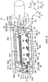
- Fig. 4 is a three-dimensional diagram illustrating a driving mechanism 8.
- the driving mechanism 8 is a mechanism for rotating the washing drum 3, and includes a base part 30, a supporting part 31, a threaded shaft 32, a motor 33, a coupler 34, a nut member 35 and a sensor 36.
- the base part 30 is formed by, for example, bending a metal plate, and integrally includes a longitudinal wall 37 and a pair of upper and lower transverse walls 38.
- the longitudinal wall 37 is formed in a shape of a rectangular plate which is thin in the left-right direction X and long in the front-rear direction Y.
- Each transverse wall 38 is formed in a shape of a rectangular plate which is thin in the up-down direction Z and long in the front-rear direction Y.
- the transverse wall 38 on the upper side Z1 is continuous for the entire upper end of the longitudinal wall 37 and extends from the upper end to the left side X1
- the transverse wall 38 on the lower side Z2 is continuous for almost entire lower end of the longitudinal wall 37 and extends from the lower end to the left side X1.
- each transverse wall 38 serves as a flange part 38A and is formed in a manner of being bent into a substantially right angle to the outer side in the up-down direction Z of the entire region throughout the front-rear direction Y.
- the flange part 38A of the transverse wall 38 on the upper side Z1 is formed in a manner of bending to the upper side Z1
- the flange part 38A of the transverse wall 38 on the lower side Z2 is formed in a manner of bending to the lower side Z2.
- a threaded hole 38B is formed in each flange part 38A.
- the base part 30 is formed in a manner of being bent into a shape of a crank on a boundary line between the longitudinal wall 37 and the transverse walls 38 and a circumferential local part of the flange part 38A.
- An accommodating space 30A enclosed by the longitudinal wall 37 and the pair of upper and lower transverse walls 38 is formed on the base part 30.
- the supporting part 31, the threaded shaft 32, the coupler 34, the nut member 35 and the sensor 36 are accommodated in the accommodating space 30A.
- the base part 30 is disposed between the supporting member 13 on the left side X1 and the washing drum 3 in a manner of being arranged along the left-right direction X relative to the washing drum 3, and a pair of upper and lower flange parts 38A are arranged oppositely from circumferential parts of the openings 13A of the supporting members 13 on the right side X2 and the left side X1 (with reference to Fig. 1 ).
- a screw 39 which is assembled on the supporting member 13 on the left side X1(with reference to Fig. 1 ), is also assembled in the threaded hole 38B of each flange part 38A, so that the base part 30 is mounted on the supporting member 13 on the left side X1.
- the supporting member 13 is strengthened through the base part 30.
- the rigidity of the supporting member 13 can be further increased.
- the accommodating space 30A of the base part 30 is exposed from the supporting member 13 on the left side X1 to the left side X1 via the opening 13A (with reference to Fig. 1 ).
- a pair of supporting parts 31 are arranged away from each other along the front-rear direction Y.
- the supporting part 31 on the front side Y1 is arranged on the front end of the longitudinal wall 37 of the base part 30, and the supporting part 31 on the rear side Y2 is arranged on the rear end of the longitudinal wall 37.
- Each supporting part 31 is formed by, for example, bending the metal plate.
- Each supporting part 31 integrally includes a body part 40 and a base part 41.
- the body part 40 is in a shape of a plate which is thin in the front-rear direction Y, and is configured in a manner of protruding from the left side surface of the longitudinal wall 37 of the base part 30 to the left side X1.
- a bearing 42 which is annular when observed from the front-rear direction Y is mounted on the body part 40 in a manner of penetrating through the body part 40 along the front-rear direction Y.
- the base part 41 is in a shape of a plate which is thin in the left-right direction X.
- the base part 41 extends from the lower end of the body part 40 to the front side Y1, and is configured in a manner of being overlapped with the front end part of the longitudinal wall 37 from the left side X1.
- the base part 41 extends from the lower end of the body part 40 to the rear side Y2, and is arranged in a manner of being overlapped with the rear end of the longitudinal wall 37 from the left side X1.
- each supporting part 31 is fixed to the base part 30.
- the threaded shaft 32 is formed in a cylindrical shape slenderly extending along the front-rear direction Y, and a screw thread 32A which extends helically is formed almost on the entire outer circumferential surface. It should be noted that in each figure except Fig. 4 , to facilitate illustration, the screw thread 32A of the threaded shaft 32 is omitted.
- the front end of the threaded shaft 32 is inserted into the annular bearing 42 of the supporting part 31 on the front side Y1, and the rear end of the threaded shaft 32 is inserted into an annular bearing 42 of the supporting part 31 on the rear side Y2. In this state, the threaded shaft 32 is supported on both ends by a pair of front and rear supporting parts 31 in a manner of rotation.
- the motor 33 is a common electric motor, and has an output shaft 44 protruding to the rear side Y2 and disposed coaxially with the threaded shaft 32.
- the motor 33 is provided with a platy bracket 45, which is thin in the front-rear direction Y, from the rear side Y2.
- the output shaft 44 is exposed from the bracket 45 to the rear side Y2.
- the output shaft 44 is arranged to be opposite, from the front side Y1, to part of the front end of the threaded shaft 32 extending further to the front side Y1 than the body part 40 of the supporting part 31 on the front side Y1.
- An upper end and a lower end of a left end of the bracket 45 serve as a pair of upper and lower flange parts 45A, and are bent into a substantially right angle to the rear side Y2.
- a threaded hole 45B is formed in each flange part 45A.
- the motor 33 is disposed between the supporting member 13 on the left side X1 and the washing drum 3 in a position closer to the front side Y1 than the base part 30, the flange parts 45A of the bracket 45 are arranged oppositely from circumferential parts of the openings 13A of the supporting members 13 on the right side X2 and the left side X1 (with reference to Fig. 1 ).
- the screw 46 (with reference to Fig. 1 )
- the motor 33 is fixed to the supporting member 13 on the left side X1 via the bracket 45.
- the motor 33 in this state is exposed from the supporting member 13 on the left side X1 to the left side X1 via the opening 13A (with reference to Fig. 1 ).
- the coupler 34 includes: a cylindrical output part 47 externally embedded into a rear end of the output shaft 44 of the motor 33 in a manner of integral rotation, a cylindrical input part 48 externally embedded into a front end of the threaded shaft 32 in a manner of integral rotation, and a buffer part 49 disposed between the output part 47 and the input part 48.
- the cylindrical output part 47 has a plurality of protrusion parts 47A arranged along the circumferential direction and protruding to the rear side Y2.
- the cylindrical input part 48 has a plurality of protrusion parts 48A arranged along the circumferential direction and protruding to the front side Y1.
- the protrusion part 47A and the protrusion part 48A are alternatively arranged in the circumferential directions of the output part 47 and the input part 48.
- the buffer part 49 is configured between the protrusion part 47A and the adjacent protrusion part 48A.
- the buffer part 49 is composed of an elastomer such as rubber and spring.
- the nut member 35 includes a body part 50, a connecting part 51 and a detected part 52.
- the body part 50 is formed on an annular nut having a screw thread (not shown) which extends helically on the inner circumferential surface, and is externally embedded into the threaded shaft 32 in such a manner that the screw thread of the nut and the screw thread 32A of the threaded shaft 32 are in mutual threaded connection.
- the motor 33 drives the threaded shaft 32 to rotate, the nut member 35 integrally moves along the axial direction (i.e., the front-rear direction Y) of the threaded shaft 32, along with rotation of the threaded shaft 32.
- the connecting part 51 is formed, for example, by bending a metal plate, and integrally includes a first part 51A, a second part 51B and a third part 51C.
- the first part 51A is formed in a shape of a plate which is thin in the front-rear direction Y and extends along the up-down direction Z, and is fixed to the body part 50 through the screws 53.
- the second part 51B is formed in a shape of a plate which is thin in the left-right direction X and extends along the up-down direction Z, and is arranged in a manner of protruding from the left end edge of the first part 51A to the front side Y1 and extending from the accommodating space 30A of the base part 30 to the left side X1, and is opposite to the body part 50 from the left side X1 (with reference to Fig. 6 below).
- a through hole 51D penetrating through the second part 51B along the left-right direction X is formed in the second part 51B.
- the second part 51B is opposite to the extending part 6D of the rotating part 6 from the right side X2.
- a connecting pin 54 (with reference to Fig. 1 ) of the guiding hole 6E, which is inserted into the extending part 6D from the left side X1, is inserted into the through hole 51D.
- the connecting pin 54 cannot be taken out of each through hole 51D and guiding hole 6E.
- the nut member 35 is connected with the rotating part 6 via the connecting pin 54. Therefore, when the nut member 35 moves along the front-rear direction Y along with rotation of the threaded shaft 32, the rotating part 6 is pulled along the front-rear direction Y by the nut member 35, so as to rotate with the washing drum 3.
- the third part 51C is formed in a shape of a plate which is thin in the up-down direction Z, protrudes from the lower end edge of the first part 51A to the front side Y1, and is opposite to the body part 50 from the lower side Z2.
- the detected part 52 is formed in a shape of a plate which is thin in the left-right direction X, and integrally includes a fixing part 52A and a front end 52B.
- the fixing part 52A is arranged in a manner of overlapping with the third part 51C of the connecting part 51 from the lower side Z2, and is fixed to the third part 51C through the screw 55.
- the front end 52B is also called as a limiting part, and is formed in a shape of a rod extending from the front end of the fixing part 52A to the right side X2.
- the sensor 36 is a sensor for detecting the rotating angle ⁇ of the washing drum 3 according to a position of the nut member 35 in the front-rear direction Y.
- the sensor 36 can be selected from an optical sensor and other non-contact optical sensors.
- a groove 36A sunken to the right side X2 and penetrating through the sensor 36 along the front-rear direction Y is formed in the left side surface of the sensor 36.
- the sensor 36 is in such a state that light transects the groove 36A along the up-down direction Z.
- the number of the sensors 36 is the same as the number of the concave parts 6C of the rotating part 6.
- five sensors are arranged in the present embodiment, and all the groove 36A are arranged in a lower region of the longitudinal wall 37 of the base part 30 along the front-rear direction Y in a manner of overlapping with each other when observed from the front-rear direction Y.
- Each sensor 36 is fixed to the longitudinal wall 37 through the screw 56.
- the spacing between adjacent sensors 36 is set correspondingly to the spacing between adjacent concave parts 6C. Therefore, in the present embodiment, although the spacing between the adjacent sensors 36 in the four sensors 36 on the rear side Y2 is fixed, the spacing between two sensors 36 located on the front-most side Y1 and the adjacent rear position is narrower than the spacing between other adjacent sensors 36.
- the above locking part 18 is located at the upper-most side Z1 and is in the same position as the concave part 6C on the front-most side Y1 in the rotating direction K; and the rotating angle ⁇ of the washing drum 3 is 60 degrees (with reference to Fig. 1 ).
- the locking part 18 is in the same position as the concave part 6C on the rear-most side Y2 in Fig.
- the rotating angle ⁇ of the washing drum 3 is 5 degrees.
- the rotating angle ⁇ is any of 5 degrees, 15 degrees, 30 degrees, 45 degrees and 60 degrees
- the front end 52B of the detected part 52 is in a state of being embedded into the groove 36A of a certain sensor 36. Therefore, five sensors 36 uniformly detect the detected part 52 on the nut member 35 in a non-contact manner, thereby detecting the rotating angle ⁇ from 5 degrees, 15 degrees, 30 degrees, 45 degrees and 60 degrees.
- Fig. 5 is a left view of a supporting member 13 and a driving mechanism 8 on the left side X1.
- Fig. 6 is a sectional view along A-A of Fig. 5 .
- the front bent part 13G is shown with a dotted line.
- the driving mechanism 8 is almost integrally arranged on the inner side of the supporting member 13 on the left side X1, i.e., between the supporting member 13 and the washing drum 3.
- most part of the driving mechanism 8 except the second part 51B is arranged in such a manner that outlines of the front bent part 13G and the rear bent part 13H accommodated in the supporting member 13 on the left side X1 when observed from the front-rear direction Y are contained in the inner side.
- the driving mechanism 8 since the driving mechanism 8 is arranged between the supporting member 13 and the washing drum 3 rather than in a manner of extending to the outer side of the supporting member 13, the washing machine 1 can become smaller in the left-right direction X. Thus, an installation space of the washing machine 1 can be saved.
- Fig. 7 is a three-dimensional diagram illustrating a washing machine 1 in a variant example when observed from the lower side Z2.
- the supporting frame 4 includes a pair of the supporting members 13 and columnar beam members 14 (with reference to Fig. 3 ) arranged between a pair of the supporting members 13 in above embodiments.
- the supporting frame 4, as shown in Fig. 7 may also be an integral member with a U shape, and integrally includes a pair of the supporting members 13 and a platy bottom member 60 erected between the lower end parts of a pair of the supporting members 13.
- the integral supporting frame 4 can increase the rigidity of each supporting member 13 and may also increase the integral rigidity of the supporting frame 4. As a result, since the distortion between a pair of the supporting members 13 can be inhibited, a situation of applying a burden to the rotating shaft 12 of the washing drum 3 due to the distortion can be inhibited.
Landscapes
- Engineering & Computer Science (AREA)
- Textile Engineering (AREA)
- Main Body Construction Of Washing Machines And Laundry Dryers (AREA)
Abstract
Description
- The present invention relates to a washing machine.
- In a washing and drying machine described in a following
patent literature 1, an outer drum part assembled with a rotating drum part with washings thrown therein is supported by a rotation supporting member through an inclined rotation supporting shaft. A pair of rotation supporting members is arranged in a manner of sandwiching the outer drum part, and each rotation supporting member is supported by an outer frame of the washing and drying machine through a hoisting rod. The outer drum part is provided with a rotation operating rope installing part, and an operating rope connected to the rotation operating rope installing part is coiled on a drum arranged on an inclined rotation motor of the outer frame. As the inclined rotation motor rotates, the operating rope moves upwards or downwards. Thus, the outer drum part obliquely rotates around the inclined rotation supporting shaft. Thus, the outer drum part is transversely inclined when the washings are thrown into the rotating drum part, and the outer drum part is disposed along a perpendicular direction during washing, rinse and dewatering. - In the washing and drying machine described in
patent literature 1, a part for mounting a hoisting rod of each rotation supporting member is located on an outer side surface of the rotation supporting member opposite to the outer drum part side. In this way, since the hoisting rod is configured in a manner of extending to the outer side of the rotation supporting member and may cause the washing and drying machine to become larger, it is difficult to reduce the space occupied by the washing and drying machine. In addition, rigidity of the rotation supporting member which rotatably supports the outer drum part is expected to be increased. - Patent Literature 1: Japanese Laid-open patent publication No.
4-166196 - The present invention is based on the background, and aims to provide a washing machine which can save an installation space and can increase rigidity of a part for rotatably supporting a washing drum in a structure including the washing drum, where the washing drum can rotate in a manner of crossing with a perpendicular direction.
- The present invention provides a washing machine, including: a washing drum accommodating washings and rotating in a manner of crossing with a perpendicular direction; a supporting member arranged on an outer side of the washing drum and rotatably supporting the washing drum; a bent part arranged on the supporting members and bent towards a side of the washing drum; and an elastic supporting member mounted on the bent part and elastically supporting the supporting member.
- In addition, in some embodiments of the present invention, the washing machine includes a driving mechanism arranged between the supporting member and the washing drum and rotating the washing drum.
- In addition, in some embodiments of the present invention, the driving mechanism includes a base part formed in a locally bent manner and mounted on the supporting member.
- In addition, in some embodiments of the present invention, the washing machine is sandwiched between a pair of the supporting members; and the washing machine includes a beam member arranged between the pair of the supporting members.
- In addition, in some embodiments of the present invention, the washing machine is sandwiched between a pair of the supporting members; the washing machine includes a supporting frame which is an integral supporting frame integrally having the pair of the supporting members; and a bottom member arranged between lower ends of the pair of the supporting members.
- According to the present invention, in the washing machine including the washing drum, the supporting member arranged on the outer side of the washing drum rotatably supports the washing drum, the washing drum can rotate in a manner of crossing with a perpendicular direction.
- The bent part, which is bent towards the washing drum, is arranged on the supporting member. Thus, rigidity of the supporting member can be increased. The elastic supporting member for elastically supporting the supporting member is mounted on the bent part. In this case, since the elastic supporting member is arranged on the side where the washing drum is (i.e., the inner side of the supporting member) rather than in a manner of extending to a side of the supporting member opposite to the washing drum (i.e., an outer side), the washing machine can become smaller. Thus, an installation space of the washing machine can be reduced.
- In addition, according to some embodiments of the present invention, since the driving mechanism for rotating the washing drum is not arranged between the supporting member and the washing drum rather than in a manner of extending to the outer side of the supporting member, the washing machine can become smaller. Thus, an installation space of the washing machine can be reduced.
- In addition, according to some embodiments of the present invention, the base part, mounted on the supporting member, of the driving mechanism is formed in a locally bent manner, so that the rigidity can be increased. Thus, since the supporting member is strengthened through the base part, the rigidity of the supporting members can be further increased.
- In addition, according to some embodiments of the present invention, the beam member is arranged between a pair of the supporting members, which are arranged in a manner of sandwiching the washing drum. Thus, the rigidity of the supporting members can be further increased.
- In addition, according to some embodiments of the present invention, a pair of the supporting members arranged in a manner of sandwiching the washing drum and the bottom member arranged between the lower ends of the pair of the supporting members are integrated to form the integral supporting frame, so that the rigidity of the supporting members can be further increased.
-
-
Fig. 1 is a schematic three-dimensional diagram illustrating a washing machine in an embodiment of the present invention. -
Fig. 2 is a three-dimensional diagram illustrating a supporting member of a supporting frame included in a washing machine. -
Fig. 3 is a three-dimensional diagram illustrating a washing machine. -
Fig. 4 is a three-dimensional diagram illustrating a driving mechanism included in a washing machine. -
Fig. 5 is a left view of a supporting member and a driving mechanism. -
Fig. 6 is a sectional view along A-A ofFig. 5 . -
Fig. 7 is a three-dimensional diagram illustrating a washing machine in a variant example. - 1: washing machine; 3: washing drum; 4: supporting frame; 5: elastic supporting member; 8: driving mechanism; 13: supporting member; 13F: bent part; 14: beam member; 30: base part; 60: bottom member; and Z: up-down direction.
- Embodiments of the present invention are specifically described below with reference to drawings.
Fig. 1 is a schematic three-dimensional diagram illustrating awashing machine 1 in an embodiment of the present invention. An up-down direction inFig. 1 is called as an up-down direction Z of thewashing machine 1; a left-right direction inFig. 1 is called as a front-rear direction Y of thewashing machine 1; and a transverse direction substantially orthogonal to paper ofFig. 1 is called as a left-right direction X. The up-down direction Z is also a perpendicular direction. In the up-down direction Z, an upper side is called as an upper side Z1; and a lower side is called as a lower side Z2. In the front-rear direction Y, a right side inFig. 1 is called as a front side Y1; and a left side inFig. 1 is called as a rear side Y2. In the left-right direction X, an outer side of the paper ofFig. 1 is called as a left side X1; and an inner side of the paper ofFig. 1 is called as a right side X2. - In the
washing machine 1, although thewashing machine 1 also includes a washing and drying machine with a clothes drying function, thewashing machine 1 hereafter, which only executes washing operation without explaining the clothes drying function, is taken as an example. The washing operation includes a washing process, a rinsing process and a dewatering process. Thewashing machine 1 includes: ahousing 2, awashing drum 3 arranged in thehousing 2, a supportingframe 4, an elastic supportingmember 5, a rotatingpart 6, anunlocking mechanism 7 and adriving mechanism 8. - The
housing 2 is, for example, made of metal, and is formed in a shape of a box. A connectingsurface 2C for connecting afront surface 2A and anupper surface 2B is arranged on thehousing 2. The connectingsurface 2C is, for example, an inclined surface which drops towards the front side Y1. An outlet-inlet (not shown) for throwing in and taking out washings from thewashing machine 1 is formed in a manner of bridging thefront surface 2A and the connectingsurface 2C. - The
washing drum 3 includes anouter drum 10 and aninner drum 11. Theouter drum 10 is, for example, made of resin, and is formed in a cylindrical shape with a bottom. An imaginary straight line passing through a center of a circle of theouter drum 10 is a central axis J of theouter drum 10. In the washing process and the rinsing process, water is stored in theouter drum 10. Acircular opening 10A through which the washings are thrown in and taken out from thewashing machine 1 is formed on an upper end of theouter drum 10 on an opposite side of a bottom wall (not shown).Metal rotating shafts 12 protruding to an outer side of the left-right direction X are arranged one by one on left and right side surfaces of theouter drum 10.Fig. 1 only shows the rotatingshaft 12 on the left side X1. The pair of left and rightrotating shafts 12 are disposed in a same position when observed from the left-right direction X. - The
inner drum 11 is, for example, made of metal, and is formed in a cylindrical shape with a bottom. Theinner drum 11 is smaller than theouter drum 10. The washings are accommodated into theinner drum 11. Acircular opening 11A through which the washings are accommodated into theinner drum 11 is formed on an upper end of theinner drum 11 on an opposite side of a bottom wall (not shown). Theinner drum 11 is coaxially accommodated into theouter drum 10. Therefore, the central axis of theinner drum 11 is the above central axis J. In a state where theinner drum 11 is accommodated into theouter drum 10, anopening 11A of theinner drum 11 is located at an inner side of anopening 10A of theouter drum 10. Theopening 10A and theopening 11A are directed to the outlet-inlet (not shown) of thehousing 2. Thus, the washings can be thrown in and taken out of theinner drum 11. A plurality of throughholes 11C are formed in acircumferential wall 11B and a bottom wall of theinner drum 11; and water in theouter drum 10 passes between theouter drum 10 and theinner drum 11 via the throughholes 11C. Therefore, a water level in theouter drum 10 is consistent with a water level in theinner drum 11. In washing operation, theinner drum 11 rotates around the central axis J under a driving force from a motor (not shown) arranged in thehousing 2. - The supporting
frame 4 is made of metal, and includes a pair of left and right supportingmembers 13 andbeam members 14 arranged between lower ends of the pair of the supportingmembers 13. Awashing drum 3 is arranged between the pair of the supportingmembers 13. Therefore, the pair of the supportingmembers 13 is arranged on an outer side of thewashing drum 3 in a manner of sandwiching thewashing drum 3 from the left-right direction X. Each supportingmember 13 is rectangular when observed from the left-right direction X and is formed in a shape of a plate which is thin in the left-right direction X. In other words, each supportingmember 13 has a specific thickness in opposite direction of thewashing drum 3, i.e., in the left-right direction X. - For the
outer drum 10 of thewashing drum 3, the rotatingshaft 12 protruding to the left side X1 penetrates through the supportingmember 13 on the left side X1, and is rotatably supported by the supportingmember 13 on the left side X1 via a bearing (not shown). For theouter drum 10, the rotating shaft 12 (not shown) protruding to the right side X2 penetrates through the supportingmember 13 on the right side X2, and is rotatably supported by the supportingmember 13 on the right side X2 via a bearing (not shown). Thus, thewashing drum 3 is supported by the supportingmembers 13 on the left and right sides of the supportingframe 4, and can rotate around the rotatingshaft 12 in a manner of crossing with the up-down direction Z. Specifically, with rotation of thewashing drum 3, the central axis J of theouter drum 10 and theinner drum 11 is inclined to the front-rear direction Y relative to the up-down direction Z. A rotating direction of thewashing drum 3 is called as a rotating direction K. - A crossing angle, which is a sharp angle between an imaginary reference axis L extending along the up-down direction Z and the central axis J, is a rotating angle θ of the
washing drum 3 relative to the reference axis L. The smaller the rotating angle θ is, the closer to the vertical posture thewashing drum 3 is. The larger the rotating angle θ is, the more inclined to the front side Y1 thewashing drum 3 is in such a manner that theopening 10A of theouter drum 10 and theopening 11A of theinner drum 11 face the front side Y1. The rotating angle θ can be changed at, for example, five levels of 5 degrees, 15 degrees, 30 degrees, 45 degrees and 60 degrees. In this case, as an example of application in thewashing machine 1, when the washings are thrown in thewashing drum 3 at the beginning of the washing operation, the rotating angle θ is set as 45 degrees in such a manner that throwing of the washings becomes easy; and then, under a condition of detecting a load of the washings or supplying water to thewashing drum 3, the rotating angle θ is set as 5 degrees. Then, in the washing process and the rinsing process, in order to promote position alternation of the washings in theinner drum 11 to realize efficient washing and rinsing, the rotating angle θ is set to change between 5 degrees and 60 degrees. - An
opening 13A penetrating through the supportingmember 13 on the left side X1 along the left-right direction X is formed in a region of the supportingmember 13 on the left side X1 and closer to the lower side Z2 than the rotatingshaft 12. Theopening 13A is formed in a substantially rectangular shape which is long in the front-rear direction Y. Referring to the three-dimensional diagram (i.e.,Fig. 2 ) of the supportingmember 13 on the left side X1, acircular opening 13B into which therotating shaft 12 is inserted and through which therotating part 6 is located is formed at the upper side Z1 of theopening 13A of the supportingmember 13 on the left side X1, as well as arectangular opening 13C located closer to the front side Y1 than theopening 13B and into which the unlockingmechanism 7 is embedded is formed at the upper side Z1 of theopening 13A of the supportingmember 13 on the left side X1. - For each supporting
member 13, aninclined part 13D from which an angle on the front upper side is cut off obliquely is formed; and the entire region of the upper end, which is closer to the rear side Y2 than theinclined part 13D, forms aflange part 13E bent into a substantially right angle to an side opposite to the side of washingdrum 3 in the left-right direction X. Herein, the side of washingdrum 3 in the left-right direction X means an inner side of the supportingmember 13, i.e., the right side X2 with respect to the supportingmember 13 on the left side X1 and the left side X1 with respect to the supportingmember 13 on the right side X2. In turn, the side opposite to the side of washingdrum 3 in the left-right direction X means an outer side of the supportingmember 13, i.e., the left side X1 with respect to the supportingmember 13 on the left side X1 and the right side X2 with respect to the supportingmember 13 on the right side X2. - A
bent part 13F bent to the side of washingdrum 3 is integrally provided on each supportingmember 13. Thebent part 13F includes a frontbent part 13G, a rearbent part 13H and a lower bent part 131. The frontbent part 13G is formed into a shape of a belt which extends along the up-down direction Z by bending an almost entire region of the front end of the supportingmember 13 closer to the lower side Z2 than theinclined part 13D towards thewashing drum 3 side into a substantially right angle. The rearbent part 13H is formed into a shape of a belt which extends along the up-down direction Z by bending an almost entire region of the rear end of the supportingmember 13 towards thewashing drum 3 side into a substantially right angle. The lower bent part 13I is formed into a shape of a belt which extends along the front-rear direction Y by bending an almost entire region of the lower end of the supportingmember 13 towards thewashing drum 3 side into a substantially right angle. - The rigidity of the supporting
member 13, and especially the bending rigidity of the left-right direction X, can be increased through thebent part 13F. It should be noted that theflange part 13E arranged on the upper end of the supportingmember 13 is also conducive to increasing the rigidity of the supportingmember 13. Since the overall resonant frequency of the supportingframe 4 of the supportingmember 13 increases by increasing the rigidity of the supportingmember 13 in this manner, vibration of the supportingframe 4 during high-speed rotation of theinner drum 11 can be inhibited especially in the dewatering process. - The front
bent part 13G and the rearbent part 13H each is cut from the side of washingdrum 3 along the up-down direction Z to form anotch 13K, such that theupper part 13J is narrower than thelower part 13L along the left-right direction X. Thenotch 13K is located in a position which is reachable to the vibratingwashing drum 3 in washing operation. Therefore, thewashing drum 3 can be prevented from contacting with the frontbent part 13G and the rearbent part 13H in the washing operation. A plurality of large or small throughholes 13M penetrating through thelower part 13L along the front-rear direction Y are formed in the upper region of thelower part 13L. An edge of the side of washingdrum 3 on the lower region of thelower part 13L is formed in such a manner: the edge is inclined to a side opposite to the side of washingdrum 3 as dropping to the lower side Z2. Thus, the lower region of thelower part 13L becomes narrow in the left-right direction X as dropping to the lower side Z2. - With reference to the three-dimensional diagram (i.e.,
Fig. 3 ) for observing thewashing machine 1 from the lower side Z2, acceptingparts 15 are fixed on the upper regions of the respectivelower parts 13L of the frontbent part 13G and the rearbent part 13H. Each acceptingpart 15 is made of, for example, resin, and is formed into a shape of a box which is slightly longer in the up-down direction Z. Aconcave part 15A sinking from a lower surface to the upper side Z1 is formed in each acceptingpart 15. The acceptingpart 15 is arranged to be opposite to thelower part 13L of the frontbent part 13G from the front side Y1 and opposite to thelower part 13L of the rearbent part 13H from the rear side Y2. A claw (not shown) arranged on the acceptingpart 15 is embedded into part of the throughholes 13M (with reference toFig. 2 ) in the upper region of thelower part 13L, so that the acceptingpart 15 is located on thelower part 13L. Screws (not shown) penetrating through other throughholes 13M in the upper region of thelower part 13L are assembled on the acceptingpart 15, so that the acceptingpart 15 is fixed to thelower part 13L. - The elastic supporting
members 5 are also called as hoisting rods, and are formed in a shape of rod which has a length in the vertical direction and has afriction damper 16 at the lower end. There are four elastic supportingmembers 5 arranged at four corners in thehousing 2 when observed from top, i.e., from the upper side Z1. The elastic supportingmembers 5 are in a state of being suspended from the upper part of thehousing 2, and specifically from a metal outer frame (not shown) forming part of thehousing 2. - Among two elastic supporting
members 5 arranged front and back on the left side X1, a lower end of the elastic supportingmember 5 on the front side Y1 is connected with the acceptingpart 15 of a frontbent part 13G of the supportingmember 13 arranged at the left side X1, and a lower end of the elastic supportingmember 5 on the rear side Y2 is connected with the acceptingpart 15 of a rearbent part 13H of the supportingmember 13 arranged on the left side X1. Among two elastic supportingmembers 5 arranged front and back on the right side X2, a lower end of the elastic supportingmember 5 on the front side Y1 is connected with the acceptingpart 15 of the frontbent part 13G of the supportingmember 13 arranged on the right side X2, and a lower end of the elastic supporting member 5 (not shown) on the rear side Y2 is connected with the accepting part 15 (not shown) of the rearbent part 13H of the supportingmember 13 arranged on the right side X2. - The lower end of each elastic supporting
member 5 is embedded into theconcave part 15A of the acceptingpart 15 from the lower side Z2 and thus is connected with the acceptingpart 15, and is mounted on the frontbent part 13G or the rearbent part 13H through the acceptingpart 15. A stick-shaped part of the elastic supporting member closer to the upper side Z1 than the lower end penetrates through the acceptingpart 15, extends to the upper side Z1 of the acceptingpart 15 and is connected with the outer frame (not shown). Thus, the supportingframe 4 having the supportingmember 13, thewashing drum 3 supported by the supportingframe 4, and the motor (not shown) for rotating theinner drum 11 are elastically supported by the elastic supportingmember 5. - The elastic supporting
member 5 mounted on the frontbent part 13G and the rearbent part 13H which are bent from the supportingmember 13 to the side of washingdrum 3 in the left-right direction X is arranged on the side of washing drum (i.e., the inner side of the supporting member 13) rather than in a manner of extending to a side of the supportingmember 13 opposite to the washing drum (i.e., an outer side). Thus, thewashing machine 1 can become smaller in the left-right direction X. Thus, an installation space of thewashing machine 1 can be reduced. Therefore, since the size of thewashing machine 1 having structures of therotating part 6, the unlockingmechanism 7 and thedriving mechanism 8 for rotating thewashing drum 3 can be controlled to be the same as a common washing machine without such structures, thewashing machine 1 can be arranged on a waterproof disk of an existing size. - Two
beam members 14 are arranged and each is formed into a shape of column which is thin and is long in the left-right direction X. The twobeam members 14 are respectively arranged between the front end and between the rear end of the lower bent part 13I of a pair of the supportingmembers 13. Thus, the rigidity of each supportingmember 13 and the integral rigidity of the supportingframe 4 are further increased. As a result, since distortion between a pair of the supportingmembers 13 can be inhibited, a situation of applying a burden to therotating shaft 12 of thewashing drum 3 due to the distortion can be inhibited. - The
rotating part 6 is a substantially fan-shaped metal plate which is thin in the left-right direction X and protrudes to the front side Y1 when observed from the left-right direction X. Therotating part 6 has an outercircumferential edge 6A which is formed in a circular arc shape along the rotating direction K and protrudes to the front side Y1. A throughhole 6B penetrating through therotating part 6 along the left-right direction X is formed in a position on therotating part 6 consistent with a center of curvature of the outercircumferential edge 6A. A plurality ofconcave parts 6C are formed at the outercircumferential edge 6A, and fiveconcave parts 6C are formed herein. Theconcave parts 6C are sunken towards the throughhole 6B, penetrate through therotating part 6 along the left-right direction X, and are arranged along the rotating direction K. The spacing between adjacentconcave parts 6C can be fixed or can be changed according to the position of therotating part 6. In the present embodiment, for the rotating angle θ set as 5 degrees, 15 degrees, 30 degrees, 45 degrees and 60 degrees, in therotating part 6 under a posture as shown inFig. 3 , the spacing between twoconcave parts 6C located on a rear-most side Y2 and the position adjacent to the rear-most side Y2 is 10 degrees in the rotating direction K, i.e., in the circumferential direction using the throughhole 6B as a center; and the spacing between other adjacentconcave parts 6C is fixed as 15 degrees. - The
rotating part 6 is arranged to be closer to the left side X1 than the supportingmember 13 on the left side X1. The rotatingshaft 12 of theouter drum 10 of thewashing drum 3, protruding to the left side X1 and penetrating through the supportingmember 13 on the left side X1, is inserted into the throughhole 6B of therotating part 6, and is fixed to therotating part 6. Thus, therotating part 6 is connected to thewashing drum 3 in a manner of integral rotation via the rotatingshaft 12. - In the
rotating part 6 under the posture inFig. 3 , at the rear end of the outercircumferential edge 6A, an extendingpart 6D protruding to the lower side Z2 and specifically protruding to the outer side in the radial direction R of therotating part 6 using the throughhole 6B as a center is integrally arranged. The extendingpart 6D is formed in a shape of a plate which is long in the radial direction R and thin in the left-right direction X. A guidinghole 6E which is long in the radial direction R and penetrates through the extendingpart 6D along the left-right direction X is formed in the extendingpart 6D. Both ends of a long edge direction of the guidinghole 6E are in a blocked state. In the up-down direction Z, the guidinghole 6E is located in the same position as theopening 13A of the supportingmember 13 on the left side X1. Regardless of a value of the rotating angle θ from 5 degrees to 60 degrees, the guidinghole 6E is always opposite to theopening 13A from the left side X1. - The unlocking
mechanism 7 is fixed to a left side surface of the supportingmember 13 on the left side X1. The unlockingmechanism 7 includes abody part 17 and a lockingpart 18. An actuator (not shown) composed of a solenoid and the like is arranged on thebody part 17. The lockingpart 18 is formed in a shape of a bulge protruding from thebody part 17 to the rear side Y2, and strictly protruding to the rear upper side, and is supported by thebody part 17 in a manner of sliding in the front-rear direction Y. The actuator of thebody part 17 operates, so that the lockingpart 18 slides between an in-position for entering to the rear-most side Y2 and an out-position for exiting to a front-most side Y1. - The locking
part 18 inFig. 3 is in the in-position. Under a condition where anyconcave part 6C of therotating part 6 is in the same position as the lockingpart 18 in the rotating direction K, the lockingpart 18 enters the in-position, thereby being embedded into theconcave part 6C in the same position in the rotating direction K. Thus, rotation of therotating part 6 and thewashing drum 3 is locked. In this state, when the lockingpart 18 exits to the out-position, since the lockingpart 18 leaves theconcave part 6C, therotating part 6 and thewashing drum 3 are unlocked. - In
Fig. 3 , the lockingpart 18 in the in-position is in a state of being embedded into theconcave part 6C located at the upper-most side Z1 and the front-most side Y1. At this moment, in a state where the rotating angle θ is 60 degrees, the rotation of therotating part 6 and thewashing drum 3 is locked. As theconcave part 6C into which the lockingpart 18 is embedded is anotherconcave part 6C located at the rear side Y2, the rotating angle θ is decreased; and in a state where the lockingpart 18 is embedded into theconcave part 6C at the rear-most side Y2, the rotating angle θ is 5 degrees. In this state, the rotation of therotating part 6 and thewashing drum 3 is locked. -
Fig. 4 is a three-dimensional diagram illustrating adriving mechanism 8. With reference toFig. 4 , thedriving mechanism 8 is a mechanism for rotating thewashing drum 3, and includes abase part 30, a supportingpart 31, a threadedshaft 32, amotor 33, acoupler 34, anut member 35 and asensor 36. - The
base part 30 is formed by, for example, bending a metal plate, and integrally includes alongitudinal wall 37 and a pair of upper and lowertransverse walls 38. Thelongitudinal wall 37 is formed in a shape of a rectangular plate which is thin in the left-right direction X and long in the front-rear direction Y. Eachtransverse wall 38 is formed in a shape of a rectangular plate which is thin in the up-down direction Z and long in the front-rear direction Y. For the pair oftransverse walls 38, thetransverse wall 38 on the upper side Z1 is continuous for the entire upper end of thelongitudinal wall 37 and extends from the upper end to the left side X1, and thetransverse wall 38 on the lower side Z2 is continuous for almost entire lower end of thelongitudinal wall 37 and extends from the lower end to the left side X1. - The left end of each
transverse wall 38 serves as aflange part 38A and is formed in a manner of being bent into a substantially right angle to the outer side in the up-down direction Z of the entire region throughout the front-rear direction Y. Theflange part 38A of thetransverse wall 38 on the upper side Z1 is formed in a manner of bending to the upper side Z1, and theflange part 38A of thetransverse wall 38 on the lower side Z2 is formed in a manner of bending to the lower side Z2. A threadedhole 38B is formed in eachflange part 38A. - In this way, the
base part 30 is formed in a manner of being bent into a shape of a crank on a boundary line between thelongitudinal wall 37 and thetransverse walls 38 and a circumferential local part of theflange part 38A. Anaccommodating space 30A enclosed by thelongitudinal wall 37 and the pair of upper and lowertransverse walls 38 is formed on thebase part 30. The supportingpart 31, the threadedshaft 32, thecoupler 34, thenut member 35 and thesensor 36 are accommodated in theaccommodating space 30A. - The
base part 30 is disposed between the supportingmember 13 on the left side X1 and thewashing drum 3 in a manner of being arranged along the left-right direction X relative to thewashing drum 3, and a pair of upper andlower flange parts 38A are arranged oppositely from circumferential parts of theopenings 13A of the supportingmembers 13 on the right side X2 and the left side X1 (with reference toFig. 1 ). Ascrew 39, which is assembled on the supportingmember 13 on the left side X1(with reference toFig. 1 ), is also assembled in the threadedhole 38B of eachflange part 38A, so that thebase part 30 is mounted on the supportingmember 13 on the left side X1. Since thebase part 30 formed in the locally bent manner as mentioned above can increase rigidity, the supportingmember 13 is strengthened through thebase part 30. Thus, the rigidity of the supportingmember 13 can be further increased. Theaccommodating space 30A of thebase part 30 is exposed from the supportingmember 13 on the left side X1 to the left side X1 via theopening 13A (with reference toFig. 1 ). - A pair of supporting
parts 31 are arranged away from each other along the front-rear direction Y. The supportingpart 31 on the front side Y1 is arranged on the front end of thelongitudinal wall 37 of thebase part 30, and the supportingpart 31 on the rear side Y2 is arranged on the rear end of thelongitudinal wall 37. Each supportingpart 31 is formed by, for example, bending the metal plate. Each supportingpart 31 integrally includes abody part 40 and abase part 41. Thebody part 40 is in a shape of a plate which is thin in the front-rear direction Y, and is configured in a manner of protruding from the left side surface of thelongitudinal wall 37 of thebase part 30 to the left side X1. A bearing 42 which is annular when observed from the front-rear direction Y is mounted on thebody part 40 in a manner of penetrating through thebody part 40 along the front-rear direction Y. Thebase part 41 is in a shape of a plate which is thin in the left-right direction X. For the supportingpart 31 on the front side Y1, thebase part 41 extends from the lower end of thebody part 40 to the front side Y1, and is configured in a manner of being overlapped with the front end part of thelongitudinal wall 37 from the left side X1. For the supportingpart 31 on the rear side Y2, thebase part 41 extends from the lower end of thebody part 40 to the rear side Y2, and is arranged in a manner of being overlapped with the rear end of thelongitudinal wall 37 from the left side X1. By assembling thescrews 43 on thebase part 41 and thelongitudinal wall 37, each supportingpart 31 is fixed to thebase part 30. - The threaded
shaft 32 is formed in a cylindrical shape slenderly extending along the front-rear direction Y, and ascrew thread 32A which extends helically is formed almost on the entire outer circumferential surface. It should be noted that in each figure exceptFig. 4 , to facilitate illustration, thescrew thread 32A of the threadedshaft 32 is omitted. The front end of the threadedshaft 32 is inserted into theannular bearing 42 of the supportingpart 31 on the front side Y1, and the rear end of the threadedshaft 32 is inserted into anannular bearing 42 of the supportingpart 31 on the rear side Y2. In this state, the threadedshaft 32 is supported on both ends by a pair of front and rear supportingparts 31 in a manner of rotation. - The
motor 33 is a common electric motor, and has anoutput shaft 44 protruding to the rear side Y2 and disposed coaxially with the threadedshaft 32. Themotor 33 is provided with aplaty bracket 45, which is thin in the front-rear direction Y, from the rear side Y2. Theoutput shaft 44 is exposed from thebracket 45 to the rear side Y2. Theoutput shaft 44 is arranged to be opposite, from the front side Y1, to part of the front end of the threadedshaft 32 extending further to the front side Y1 than thebody part 40 of the supportingpart 31 on the front side Y1. An upper end and a lower end of a left end of thebracket 45 serve as a pair of upper andlower flange parts 45A, and are bent into a substantially right angle to the rear side Y2. A threadedhole 45B is formed in eachflange part 45A. - The
motor 33 is disposed between the supportingmember 13 on the left side X1 and thewashing drum 3 in a position closer to the front side Y1 than thebase part 30, theflange parts 45A of thebracket 45 are arranged oppositely from circumferential parts of theopenings 13A of the supportingmembers 13 on the right side X2 and the left side X1 (with reference toFig. 1 ). By assembling the screw 46 (with reference toFig. 1 ), which is assembled on the supportingmember 13 on the left side X1, to the threadedhole 45B of eachflange part 45A, themotor 33 is fixed to the supportingmember 13 on the left side X1 via thebracket 45. Themotor 33 in this state is exposed from the supportingmember 13 on the left side X1 to the left side X1 via theopening 13A (with reference toFig. 1 ). - The
coupler 34 includes: acylindrical output part 47 externally embedded into a rear end of theoutput shaft 44 of themotor 33 in a manner of integral rotation, acylindrical input part 48 externally embedded into a front end of the threadedshaft 32 in a manner of integral rotation, and abuffer part 49 disposed between theoutput part 47 and theinput part 48. Thecylindrical output part 47 has a plurality ofprotrusion parts 47A arranged along the circumferential direction and protruding to the rear side Y2. Thecylindrical input part 48 has a plurality of protrusion parts 48A arranged along the circumferential direction and protruding to the front side Y1. Theprotrusion part 47A and the protrusion part 48A are alternatively arranged in the circumferential directions of theoutput part 47 and theinput part 48. Thebuffer part 49 is configured between theprotrusion part 47A and the adjacent protrusion part 48A. Thebuffer part 49 is composed of an elastomer such as rubber and spring. Theoutput shaft 44 and the threadedshaft 32 are connected via thecoupler 34 in a manner of integral connection. Therefore, when themotor 33 is driven to rotate theoutput shaft 44, the threadedshaft 32 and theoutput shaft 44 rotate integrally. - The
nut member 35 includes abody part 50, a connecting part 51 and a detectedpart 52. Thebody part 50 is formed on an annular nut having a screw thread (not shown) which extends helically on the inner circumferential surface, and is externally embedded into the threadedshaft 32 in such a manner that the screw thread of the nut and thescrew thread 32A of the threadedshaft 32 are in mutual threaded connection. When themotor 33 drives the threadedshaft 32 to rotate, thenut member 35 integrally moves along the axial direction (i.e., the front-rear direction Y) of the threadedshaft 32, along with rotation of the threadedshaft 32. - The connecting part 51 is formed, for example, by bending a metal plate, and integrally includes a
first part 51A, asecond part 51B and athird part 51C. Thefirst part 51A is formed in a shape of a plate which is thin in the front-rear direction Y and extends along the up-down direction Z, and is fixed to thebody part 50 through thescrews 53. Thesecond part 51B is formed in a shape of a plate which is thin in the left-right direction X and extends along the up-down direction Z, and is arranged in a manner of protruding from the left end edge of thefirst part 51A to the front side Y1 and extending from theaccommodating space 30A of thebase part 30 to the left side X1, and is opposite to thebody part 50 from the left side X1 (with reference toFig. 6 below). A throughhole 51D penetrating through thesecond part 51B along the left-right direction X is formed in thesecond part 51B. - The
second part 51B is opposite to the extendingpart 6D of therotating part 6 from the right side X2. A connecting pin 54 (with reference toFig. 1 ) of the guidinghole 6E, which is inserted into the extendingpart 6D from the left side X1, is inserted into the throughhole 51D. The connectingpin 54 cannot be taken out of each throughhole 51D and guidinghole 6E. Thenut member 35 is connected with therotating part 6 via the connectingpin 54. Therefore, when thenut member 35 moves along the front-rear direction Y along with rotation of the threadedshaft 32, therotating part 6 is pulled along the front-rear direction Y by thenut member 35, so as to rotate with thewashing drum 3. When therotating part 6 rotates, the connectingpin 54 moves along the direction of the long edge of the guidinghole 6E in the guidinghole 6E. Thethird part 51C is formed in a shape of a plate which is thin in the up-down direction Z, protrudes from the lower end edge of thefirst part 51A to the front side Y1, and is opposite to thebody part 50 from the lower side Z2. - The detected
part 52 is formed in a shape of a plate which is thin in the left-right direction X, and integrally includes a fixingpart 52A and afront end 52B. The fixingpart 52A is arranged in a manner of overlapping with thethird part 51C of the connecting part 51 from the lower side Z2, and is fixed to thethird part 51C through thescrew 55. Thefront end 52B is also called as a limiting part, and is formed in a shape of a rod extending from the front end of the fixingpart 52A to the right side X2. - The
sensor 36 is a sensor for detecting the rotating angle θ of thewashing drum 3 according to a position of thenut member 35 in the front-rear direction Y. Thesensor 36 can be selected from an optical sensor and other non-contact optical sensors. When the optical sensor is used, agroove 36A sunken to the right side X2 and penetrating through thesensor 36 along the front-rear direction Y is formed in the left side surface of thesensor 36. Thesensor 36 is in such a state that light transects thegroove 36A along the up-down direction Z. The number of thesensors 36 is the same as the number of theconcave parts 6C of therotating part 6. In other words, five sensors are arranged in the present embodiment, and all thegroove 36A are arranged in a lower region of thelongitudinal wall 37 of thebase part 30 along the front-rear direction Y in a manner of overlapping with each other when observed from the front-rear direction Y. Eachsensor 36 is fixed to thelongitudinal wall 37 through thescrew 56. The spacing betweenadjacent sensors 36 is set correspondingly to the spacing between adjacentconcave parts 6C. Therefore, in the present embodiment, although the spacing between theadjacent sensors 36 in the foursensors 36 on the rear side Y2 is fixed, the spacing between twosensors 36 located on the front-most side Y1 and the adjacent rear position is narrower than the spacing between otheradjacent sensors 36. - When the
nut member 35 moves along the front-rear direction Y along with rotation of the threadedshaft 32, thefront end 52B of the detectedpart 52 arranged on thenut member 35 penetrates through thegroove 36A of eachsensor 36. Detection light of thegroove 36A is blocked by thefront end 52B in a state of being embedded into thegroove 36A. - As shown in
Fig. 4 , when thefront end part 52B of the detectedpart 52 is in a state of being embedded into thegroove 36A of thesensor 36 on the rear-most side Y2, the above lockingpart 18 is located at the upper-most side Z1 and is in the same position as theconcave part 6C on the front-most side Y1 in the rotating direction K; and the rotating angle θ of thewashing drum 3 is 60 degrees (with reference toFig. 1 ). On the other hand, in a state that thefront end 52B of the detectedpart 52 is embedded into thegroove 36A of thesensor 36 on the front-most side Y1, the lockingpart 18 is in the same position as theconcave part 6C on the rear-most side Y2 inFig. 1 in the rotating direction K; and the rotating angle θ of thewashing drum 3 is 5 degrees. When the rotating angle θ is any of 5 degrees, 15 degrees, 30 degrees, 45 degrees and 60 degrees, thefront end 52B of the detectedpart 52 is in a state of being embedded into thegroove 36A of acertain sensor 36. Therefore, fivesensors 36 uniformly detect the detectedpart 52 on thenut member 35 in a non-contact manner, thereby detecting the rotating angle θ from 5 degrees, 15 degrees, 30 degrees, 45 degrees and 60 degrees. -
Fig. 5 is a left view of a supportingmember 13 and adriving mechanism 8 on the left side X1.Fig. 6 is a sectional view along A-A ofFig. 5 . InFig. 6 , to facilitate description, the frontbent part 13G is shown with a dotted line. With reference toFig. 6 , for thedriving mechanism 8, although thesecond part 51B of the connecting part 51 is arranged in a manner of extending further to the left side X1 than the supportingmember 13 on the left side X1, thedriving mechanism 8 is almost integrally arranged on the inner side of the supportingmember 13 on the left side X1, i.e., between the supportingmember 13 and thewashing drum 3. Specifically, most part of thedriving mechanism 8 except thesecond part 51B is arranged in such a manner that outlines of the frontbent part 13G and the rearbent part 13H accommodated in the supportingmember 13 on the left side X1 when observed from the front-rear direction Y are contained in the inner side. In this way, since thedriving mechanism 8 is arranged between the supportingmember 13 and thewashing drum 3 rather than in a manner of extending to the outer side of the supportingmember 13, thewashing machine 1 can become smaller in the left-right direction X. Thus, an installation space of thewashing machine 1 can be saved. -
Fig. 7 is a three-dimensional diagram illustrating awashing machine 1 in a variant example when observed from the lower side Z2. The supportingframe 4 includes a pair of the supportingmembers 13 and columnar beam members 14 (with reference toFig. 3 ) arranged between a pair of the supportingmembers 13 in above embodiments. Instead, the supportingframe 4, as shown inFig. 7 , may also be an integral member with a U shape, and integrally includes a pair of the supportingmembers 13 and a platy bottom member 60 erected between the lower end parts of a pair of the supportingmembers 13. The integral supportingframe 4 can increase the rigidity of each supportingmember 13 and may also increase the integral rigidity of the supportingframe 4. As a result, since the distortion between a pair of the supportingmembers 13 can be inhibited, a situation of applying a burden to therotating shaft 12 of thewashing drum 3 due to the distortion can be inhibited. - The present invention is not limited to embodiments described above, and can be changed in various modes within a scope recorded in claims.
- In addition, as long as the movement of the
nut member 35 in the front-rear direction Y, i.e., the rotation of thewashing drum 3, can be limited when the driving of themotor 33 is stopped, the unlockingmechanism 7 and theconcave part 6C of therotating part 6 can be omitted. Thus, stepless adjustment can be made to the rotating angle θ.
Claims (5)
- A washing machine, comprising:a washing drum accommodating washings and rotating in a manner of crossing with a perpendicular direction;a supporting member arranged on an outer side of the washing drum and rotatably supporting the washing drum;a bent part arranged on the supporting member and bent to a side of the washing drum; andan elastic supporting member mounted on the bent part and elastically supporting the supporting member.
- The washing machine according to claim 1, wherein
the washing machine further comprises a driving mechanism arranged between the supporting member and the washing drum and rotating the washing drum. - The washing machine according to claim 2, wherein
the driving mechanism comprises a base part formed in a locally bent manner and mounted on the supporting member. - The washing machine according to any one of claims 1-3, wherein
the washing drum is sandwiched between a pair of the supporting members; and
the washing machine comprises a beam member arranged between the pair of the supporting members. - The washing machine according to any one of claims 1-3, wherein
the washing machine is sandwiched between a pair of the supporting members; and
the washing machine comprises a supporting frame, the supporting frame is an integral supporting frame integrally having the pair of the supporting members and a bottom member arranged between lower ends of the pair of the supporting members.
Applications Claiming Priority (2)
| Application Number | Priority Date | Filing Date | Title |
|---|---|---|---|
| JP2015166227A JP6818197B2 (en) | 2015-08-25 | 2015-08-25 | Washing machine |
| PCT/CN2016/096689 WO2017032326A1 (en) | 2015-08-25 | 2016-08-25 | Washing machine |
Publications (3)
| Publication Number | Publication Date |
|---|---|
| EP3342916A1 true EP3342916A1 (en) | 2018-07-04 |
| EP3342916A4 EP3342916A4 (en) | 2019-04-10 |
| EP3342916B1 EP3342916B1 (en) | 2020-07-01 |
Family
ID=58099610
Family Applications (1)
| Application Number | Title | Priority Date | Filing Date |
|---|---|---|---|
| EP16838584.7A Active EP3342916B1 (en) | 2015-08-25 | 2016-08-25 | Washing machine |
Country Status (6)
| Country | Link |
|---|---|
| US (1) | US20180171527A1 (en) |
| EP (1) | EP3342916B1 (en) |
| JP (1) | JP6818197B2 (en) |
| KR (1) | KR102090012B1 (en) |
| CN (1) | CN107923105B (en) |
| WO (1) | WO2017032326A1 (en) |
Families Citing this family (2)
| Publication number | Priority date | Publication date | Assignee | Title |
|---|---|---|---|---|
| CN107354669B (en) * | 2017-08-28 | 2019-12-17 | 无锡小天鹅电器有限公司 | Clothes treating device |
| US20210301443A1 (en) * | 2020-03-24 | 2021-09-30 | Varand Abrahamian | Washing machine with drum that rotates in two dimensions |
Family Cites Families (23)
| Publication number | Priority date | Publication date | Assignee | Title |
|---|---|---|---|---|
| US2343102A (en) * | 1940-07-09 | 1944-02-29 | Edwin F Wesely | Combined centrifugal extractor and tumbler |
| US2486668A (en) * | 1943-04-08 | 1949-11-01 | Albert R Miller | Automatic sequentially operated washing machine |
| US2506280A (en) * | 1944-05-10 | 1950-05-02 | Leon W Ryder | Clothes-washing machine |
| US2782622A (en) * | 1953-07-02 | 1957-02-26 | Gen Motors Corp | Domestic appliances |
| FR1543336A (en) * | 1966-08-31 | 1968-10-25 | Philips Nv | Washing machine |
| GB1161213A (en) * | 1966-08-31 | 1969-08-13 | Philips Electronic Associated | Improvements in or relating to Domestic Washing Machines. |
| JPS6049977U (en) * | 1983-09-12 | 1985-04-08 | セイレイ工業株式会社 | Automatic sorting adjustment device in paddy coarse sorter |
| IL75320A0 (en) * | 1985-05-28 | 1985-09-29 | Robomatix Ltd | Variable cam mechanism |
| JP2650722B2 (en) * | 1988-06-20 | 1997-09-03 | 松下電器産業株式会社 | Washing and drying machine |
| JPH03186292A (en) * | 1989-12-18 | 1991-08-14 | Hitachi Ltd | Washing machine |
| JPH04166196A (en) * | 1990-10-31 | 1992-06-12 | Hitachi Ltd | washing equipment |
| JPH0523473A (en) * | 1991-02-28 | 1993-02-02 | Hitachi Ltd | Washing and drying machine |
| JPH051477U (en) * | 1991-05-24 | 1993-01-14 | 裕功 小泉 | Fully automatic washer / dryer |
| JPH0549793A (en) * | 1991-08-26 | 1993-03-02 | Sanyo Electric Co Ltd | Dehydrating and washing machine |
| KR19990051581A (en) * | 1997-12-19 | 1999-07-05 | 윤종용 | Damper of washing machine |
| JP2000271383A (en) * | 1999-03-23 | 2000-10-03 | Nippon Kentetsu Co Ltd | Attaching structure of mechanism and drain valve case to water tank of washing machine |
| JP2002292185A (en) * | 2001-03-29 | 2002-10-08 | Nippon Kentetsu Co Ltd | Washing machine anti-vibration device |
| DE102004002585A1 (en) * | 2004-01-16 | 2005-08-04 | Herbert Kannegiesser Gmbh | Apparatus for the wet treatment of laundry |
| JP2006000302A (en) * | 2004-06-16 | 2006-01-05 | Hitachi Home & Life Solutions Inc | Drum type washing machine |
| EP1849905B1 (en) * | 2005-02-02 | 2008-11-19 | Girbau, S.A. | Washing machine support structure |
| JP2006311978A (en) * | 2005-05-05 | 2006-11-16 | Century Riyuu Kikaku:Kk | Vertical washing machine of obliquely loading/unloading type |
| JP5291128B2 (en) * | 2011-01-07 | 2013-09-18 | シャープ株式会社 | Washing machine |
| KR101596104B1 (en) * | 2013-12-26 | 2016-02-26 | 주식회사 포스코 | Assembly for washing machine using the frame for reducing vibration |
-
2015
- 2015-08-25 JP JP2015166227A patent/JP6818197B2/en active Active
-
2016
- 2016-08-25 KR KR1020187008366A patent/KR102090012B1/en not_active Expired - Fee Related
- 2016-08-25 EP EP16838584.7A patent/EP3342916B1/en active Active
- 2016-08-25 CN CN201680049051.0A patent/CN107923105B/en active Active
- 2016-08-25 US US15/755,474 patent/US20180171527A1/en not_active Abandoned
- 2016-08-25 WO PCT/CN2016/096689 patent/WO2017032326A1/en not_active Ceased
Also Published As
| Publication number | Publication date |
|---|---|
| KR20180042398A (en) | 2018-04-25 |
| EP3342916A4 (en) | 2019-04-10 |
| JP6818197B2 (en) | 2021-01-20 |
| CN107923105A (en) | 2018-04-17 |
| WO2017032326A1 (en) | 2017-03-02 |
| JP2017042327A (en) | 2017-03-02 |
| CN107923105B (en) | 2020-03-13 |
| KR102090012B1 (en) | 2020-03-18 |
| EP3342916B1 (en) | 2020-07-01 |
| US20180171527A1 (en) | 2018-06-21 |
Similar Documents
| Publication | Publication Date | Title |
|---|---|---|
| KR101185695B1 (en) | Vibration controlling device of washing machine | |
| EP2011912A1 (en) | Dynamic vibration absorber | |
| EP2692931B1 (en) | Laundry processing machine | |
| EP3342916B1 (en) | Washing machine | |
| CN107923099B (en) | Washing machine | |
| WO2015180478A1 (en) | Clothes washing machine | |
| EP3342913A1 (en) | Washing machine | |
| CN108350638B (en) | washing machine | |
| EP3342918A1 (en) | Washing machine | |
| EP3346040A1 (en) | Washing machine | |
| KR20090119536A (en) | Clothing processing device | |
| TW201903240A (en) | washing machine |
Legal Events
| Date | Code | Title | Description |
|---|---|---|---|
| STAA | Information on the status of an ep patent application or granted ep patent |
Free format text: STATUS: THE INTERNATIONAL PUBLICATION HAS BEEN MADE |
|
| PUAI | Public reference made under article 153(3) epc to a published international application that has entered the european phase |
Free format text: ORIGINAL CODE: 0009012 |
|
| STAA | Information on the status of an ep patent application or granted ep patent |
Free format text: STATUS: REQUEST FOR EXAMINATION WAS MADE |
|
| 17P | Request for examination filed |
Effective date: 20180321 |
|
| AK | Designated contracting states |
Kind code of ref document: A1 Designated state(s): AL AT BE BG CH CY CZ DE DK EE ES FI FR GB GR HR HU IE IS IT LI LT LU LV MC MK MT NL NO PL PT RO RS SE SI SK SM TR |
|
| AX | Request for extension of the european patent |
Extension state: BA ME |
|
| DAV | Request for validation of the european patent (deleted) | ||
| DAX | Request for extension of the european patent (deleted) | ||
| A4 | Supplementary search report drawn up and despatched |
Effective date: 20190311 |
|
| RIC1 | Information provided on ipc code assigned before grant |
Ipc: D06F 49/06 20060101ALI20190305BHEP Ipc: D06F 37/20 20060101AFI20190305BHEP |
|
| RIC1 | Information provided on ipc code assigned before grant |
Ipc: D06F 37/20 20060101AFI20200221BHEP Ipc: D06F 23/06 20060101ALN20200221BHEP |
|
| GRAP | Despatch of communication of intention to grant a patent |
Free format text: ORIGINAL CODE: EPIDOSNIGR1 |
|
| STAA | Information on the status of an ep patent application or granted ep patent |
Free format text: STATUS: GRANT OF PATENT IS INTENDED |
|
| RIC1 | Information provided on ipc code assigned before grant |
Ipc: D06F 23/06 20060101ALN20200325BHEP Ipc: D06F 37/20 20060101AFI20200325BHEP |
|
| INTG | Intention to grant announced |
Effective date: 20200408 |
|
| GRAS | Grant fee paid |
Free format text: ORIGINAL CODE: EPIDOSNIGR3 |
|
| GRAA | (expected) grant |
Free format text: ORIGINAL CODE: 0009210 |
|
| STAA | Information on the status of an ep patent application or granted ep patent |
Free format text: STATUS: THE PATENT HAS BEEN GRANTED |
|
| AK | Designated contracting states |
Kind code of ref document: B1 Designated state(s): AL AT BE BG CH CY CZ DE DK EE ES FI FR GB GR HR HU IE IS IT LI LT LU LV MC MK MT NL NO PL PT RO RS SE SI SK SM TR |
|
| REG | Reference to a national code |
Ref country code: CH Ref legal event code: EP Ref country code: AT Ref legal event code: REF Ref document number: 1286277 Country of ref document: AT Kind code of ref document: T Effective date: 20200715 |
|
| REG | Reference to a national code |
Ref country code: IE Ref legal event code: FG4D |
|
| REG | Reference to a national code |
Ref country code: DE Ref legal event code: R096 Ref document number: 602016039276 Country of ref document: DE |
|
| REG | Reference to a national code |
Ref country code: LT Ref legal event code: MG4D |
|
| PG25 | Lapsed in a contracting state [announced via postgrant information from national office to epo] |
Ref country code: BG Free format text: LAPSE BECAUSE OF FAILURE TO SUBMIT A TRANSLATION OF THE DESCRIPTION OR TO PAY THE FEE WITHIN THE PRESCRIBED TIME-LIMIT Effective date: 20201001 |
|
| REG | Reference to a national code |
Ref country code: NL Ref legal event code: MP Effective date: 20200701 |
|
| REG | Reference to a national code |
Ref country code: AT Ref legal event code: MK05 Ref document number: 1286277 Country of ref document: AT Kind code of ref document: T Effective date: 20200701 |
|
| PG25 | Lapsed in a contracting state [announced via postgrant information from national office to epo] |
Ref country code: GR Free format text: LAPSE BECAUSE OF FAILURE TO SUBMIT A TRANSLATION OF THE DESCRIPTION OR TO PAY THE FEE WITHIN THE PRESCRIBED TIME-LIMIT Effective date: 20201002 Ref country code: SE Free format text: LAPSE BECAUSE OF FAILURE TO SUBMIT A TRANSLATION OF THE DESCRIPTION OR TO PAY THE FEE WITHIN THE PRESCRIBED TIME-LIMIT Effective date: 20200701 Ref country code: NO Free format text: LAPSE BECAUSE OF FAILURE TO SUBMIT A TRANSLATION OF THE DESCRIPTION OR TO PAY THE FEE WITHIN THE PRESCRIBED TIME-LIMIT Effective date: 20201001 Ref country code: AT Free format text: LAPSE BECAUSE OF FAILURE TO SUBMIT A TRANSLATION OF THE DESCRIPTION OR TO PAY THE FEE WITHIN THE PRESCRIBED TIME-LIMIT Effective date: 20200701 Ref country code: HR Free format text: LAPSE BECAUSE OF FAILURE TO SUBMIT A TRANSLATION OF THE DESCRIPTION OR TO PAY THE FEE WITHIN THE PRESCRIBED TIME-LIMIT Effective date: 20200701 Ref country code: PT Free format text: LAPSE BECAUSE OF FAILURE TO SUBMIT A TRANSLATION OF THE DESCRIPTION OR TO PAY THE FEE WITHIN THE PRESCRIBED TIME-LIMIT Effective date: 20201102 Ref country code: CZ Free format text: LAPSE BECAUSE OF FAILURE TO SUBMIT A TRANSLATION OF THE DESCRIPTION OR TO PAY THE FEE WITHIN THE PRESCRIBED TIME-LIMIT Effective date: 20200701 Ref country code: LT Free format text: LAPSE BECAUSE OF FAILURE TO SUBMIT A TRANSLATION OF THE DESCRIPTION OR TO PAY THE FEE WITHIN THE PRESCRIBED TIME-LIMIT Effective date: 20200701 Ref country code: ES Free format text: LAPSE BECAUSE OF FAILURE TO SUBMIT A TRANSLATION OF THE DESCRIPTION OR TO PAY THE FEE WITHIN THE PRESCRIBED TIME-LIMIT Effective date: 20200701 Ref country code: FI Free format text: LAPSE BECAUSE OF FAILURE TO SUBMIT A TRANSLATION OF THE DESCRIPTION OR TO PAY THE FEE WITHIN THE PRESCRIBED TIME-LIMIT Effective date: 20200701 |
|
| PG25 | Lapsed in a contracting state [announced via postgrant information from national office to epo] |
Ref country code: LV Free format text: LAPSE BECAUSE OF FAILURE TO SUBMIT A TRANSLATION OF THE DESCRIPTION OR TO PAY THE FEE WITHIN THE PRESCRIBED TIME-LIMIT Effective date: 20200701 Ref country code: RS Free format text: LAPSE BECAUSE OF FAILURE TO SUBMIT A TRANSLATION OF THE DESCRIPTION OR TO PAY THE FEE WITHIN THE PRESCRIBED TIME-LIMIT Effective date: 20200701 Ref country code: PL Free format text: LAPSE BECAUSE OF FAILURE TO SUBMIT A TRANSLATION OF THE DESCRIPTION OR TO PAY THE FEE WITHIN THE PRESCRIBED TIME-LIMIT Effective date: 20200701 Ref country code: IS Free format text: LAPSE BECAUSE OF FAILURE TO SUBMIT A TRANSLATION OF THE DESCRIPTION OR TO PAY THE FEE WITHIN THE PRESCRIBED TIME-LIMIT Effective date: 20201101 |
|
| PG25 | Lapsed in a contracting state [announced via postgrant information from national office to epo] |
Ref country code: NL Free format text: LAPSE BECAUSE OF FAILURE TO SUBMIT A TRANSLATION OF THE DESCRIPTION OR TO PAY THE FEE WITHIN THE PRESCRIBED TIME-LIMIT Effective date: 20200701 Ref country code: MC Free format text: LAPSE BECAUSE OF FAILURE TO SUBMIT A TRANSLATION OF THE DESCRIPTION OR TO PAY THE FEE WITHIN THE PRESCRIBED TIME-LIMIT Effective date: 20200701 |
|
| REG | Reference to a national code |
Ref country code: CH Ref legal event code: PL |
|
| REG | Reference to a national code |
Ref country code: DE Ref legal event code: R097 Ref document number: 602016039276 Country of ref document: DE |
|
| PG25 | Lapsed in a contracting state [announced via postgrant information from national office to epo] |
Ref country code: EE Free format text: LAPSE BECAUSE OF FAILURE TO SUBMIT A TRANSLATION OF THE DESCRIPTION OR TO PAY THE FEE WITHIN THE PRESCRIBED TIME-LIMIT Effective date: 20200701 Ref country code: SM Free format text: LAPSE BECAUSE OF FAILURE TO SUBMIT A TRANSLATION OF THE DESCRIPTION OR TO PAY THE FEE WITHIN THE PRESCRIBED TIME-LIMIT Effective date: 20200701 Ref country code: LI Free format text: LAPSE BECAUSE OF NON-PAYMENT OF DUE FEES Effective date: 20200831 Ref country code: LU Free format text: LAPSE BECAUSE OF NON-PAYMENT OF DUE FEES Effective date: 20200825 Ref country code: RO Free format text: LAPSE BECAUSE OF FAILURE TO SUBMIT A TRANSLATION OF THE DESCRIPTION OR TO PAY THE FEE WITHIN THE PRESCRIBED TIME-LIMIT Effective date: 20200701 Ref country code: CH Free format text: LAPSE BECAUSE OF NON-PAYMENT OF DUE FEES Effective date: 20200831 Ref country code: DK Free format text: LAPSE BECAUSE OF FAILURE TO SUBMIT A TRANSLATION OF THE DESCRIPTION OR TO PAY THE FEE WITHIN THE PRESCRIBED TIME-LIMIT Effective date: 20200701 |
|
| PLBE | No opposition filed within time limit |
Free format text: ORIGINAL CODE: 0009261 |
|
| STAA | Information on the status of an ep patent application or granted ep patent |
Free format text: STATUS: NO OPPOSITION FILED WITHIN TIME LIMIT |
|
| REG | Reference to a national code |
Ref country code: BE Ref legal event code: MM Effective date: 20200831 |
|
| PG25 | Lapsed in a contracting state [announced via postgrant information from national office to epo] |
Ref country code: AL Free format text: LAPSE BECAUSE OF FAILURE TO SUBMIT A TRANSLATION OF THE DESCRIPTION OR TO PAY THE FEE WITHIN THE PRESCRIBED TIME-LIMIT Effective date: 20200701 |
|
| 26N | No opposition filed |
Effective date: 20210406 |
|
| PG25 | Lapsed in a contracting state [announced via postgrant information from national office to epo] |
Ref country code: SK Free format text: LAPSE BECAUSE OF FAILURE TO SUBMIT A TRANSLATION OF THE DESCRIPTION OR TO PAY THE FEE WITHIN THE PRESCRIBED TIME-LIMIT Effective date: 20200701 |
|
| PG25 | Lapsed in a contracting state [announced via postgrant information from national office to epo] |
Ref country code: SI Free format text: LAPSE BECAUSE OF FAILURE TO SUBMIT A TRANSLATION OF THE DESCRIPTION OR TO PAY THE FEE WITHIN THE PRESCRIBED TIME-LIMIT Effective date: 20200701 Ref country code: IE Free format text: LAPSE BECAUSE OF NON-PAYMENT OF DUE FEES Effective date: 20200825 Ref country code: BE Free format text: LAPSE BECAUSE OF NON-PAYMENT OF DUE FEES Effective date: 20200831 |
|
| PGFP | Annual fee paid to national office [announced via postgrant information from national office to epo] |
Ref country code: IT Payment date: 20210830 Year of fee payment: 6 Ref country code: FR Payment date: 20210819 Year of fee payment: 6 |
|
| PGFP | Annual fee paid to national office [announced via postgrant information from national office to epo] |
Ref country code: GB Payment date: 20210824 Year of fee payment: 6 Ref country code: DE Payment date: 20210819 Year of fee payment: 6 |
|
| PG25 | Lapsed in a contracting state [announced via postgrant information from national office to epo] |
Ref country code: TR Free format text: LAPSE BECAUSE OF FAILURE TO SUBMIT A TRANSLATION OF THE DESCRIPTION OR TO PAY THE FEE WITHIN THE PRESCRIBED TIME-LIMIT Effective date: 20200701 Ref country code: MT Free format text: LAPSE BECAUSE OF FAILURE TO SUBMIT A TRANSLATION OF THE DESCRIPTION OR TO PAY THE FEE WITHIN THE PRESCRIBED TIME-LIMIT Effective date: 20200701 Ref country code: CY Free format text: LAPSE BECAUSE OF FAILURE TO SUBMIT A TRANSLATION OF THE DESCRIPTION OR TO PAY THE FEE WITHIN THE PRESCRIBED TIME-LIMIT Effective date: 20200701 |
|
| PG25 | Lapsed in a contracting state [announced via postgrant information from national office to epo] |
Ref country code: MK Free format text: LAPSE BECAUSE OF FAILURE TO SUBMIT A TRANSLATION OF THE DESCRIPTION OR TO PAY THE FEE WITHIN THE PRESCRIBED TIME-LIMIT Effective date: 20200701 |
|
| REG | Reference to a national code |
Ref country code: DE Ref legal event code: R119 Ref document number: 602016039276 Country of ref document: DE |
|
| GBPC | Gb: european patent ceased through non-payment of renewal fee |
Effective date: 20220825 |
|
| PG25 | Lapsed in a contracting state [announced via postgrant information from national office to epo] |
Ref country code: IT Free format text: LAPSE BECAUSE OF NON-PAYMENT OF DUE FEES Effective date: 20220825 Ref country code: FR Free format text: LAPSE BECAUSE OF NON-PAYMENT OF DUE FEES Effective date: 20220831 Ref country code: DE Free format text: LAPSE BECAUSE OF NON-PAYMENT OF DUE FEES Effective date: 20230301 |
|
| PG25 | Lapsed in a contracting state [announced via postgrant information from national office to epo] |
Ref country code: GB Free format text: LAPSE BECAUSE OF NON-PAYMENT OF DUE FEES Effective date: 20220825 |