EP3342735A1 - Sheet feeding apparatus and image forming apparatus - Google Patents
Sheet feeding apparatus and image forming apparatus Download PDFInfo
- Publication number
- EP3342735A1 EP3342735A1 EP17204395.2A EP17204395A EP3342735A1 EP 3342735 A1 EP3342735 A1 EP 3342735A1 EP 17204395 A EP17204395 A EP 17204395A EP 3342735 A1 EP3342735 A1 EP 3342735A1
- Authority
- EP
- European Patent Office
- Prior art keywords
- sheet
- holding
- feed
- urging
- feeding apparatus
- Prior art date
- Legal status (The legal status is an assumption and is not a legal conclusion. Google has not performed a legal analysis and makes no representation as to the accuracy of the status listed.)
- Withdrawn
Links
- 238000000926 separation method Methods 0.000 claims abstract description 23
- 229920005989 resin Polymers 0.000 claims abstract description 21
- 239000011347 resin Substances 0.000 claims abstract description 21
- 239000002184 metal Substances 0.000 claims abstract description 13
- 239000000463 material Substances 0.000 claims description 10
- 238000003825 pressing Methods 0.000 claims description 5
- 239000007769 metal material Substances 0.000 description 6
- 238000000034 method Methods 0.000 description 4
- 239000003086 colorant Substances 0.000 description 2
- 238000011144 upstream manufacturing Methods 0.000 description 2
- 238000004140 cleaning Methods 0.000 description 1
- 238000010586 diagram Methods 0.000 description 1
- 230000000694 effects Effects 0.000 description 1
- 238000012986 modification Methods 0.000 description 1
- 230000004048 modification Effects 0.000 description 1
- 238000005096 rolling process Methods 0.000 description 1
- 229920003002 synthetic resin Polymers 0.000 description 1
- 239000000057 synthetic resin Substances 0.000 description 1
Images






Classifications
-
- G—PHYSICS
- G03—PHOTOGRAPHY; CINEMATOGRAPHY; ANALOGOUS TECHNIQUES USING WAVES OTHER THAN OPTICAL WAVES; ELECTROGRAPHY; HOLOGRAPHY
- G03G—ELECTROGRAPHY; ELECTROPHOTOGRAPHY; MAGNETOGRAPHY
- G03G15/00—Apparatus for electrographic processes using a charge pattern
- G03G15/65—Apparatus which relate to the handling of copy material
- G03G15/6502—Supplying of sheet copy material; Cassettes therefor
- G03G15/6511—Feeding devices for picking up or separation of copy sheets
-
- B—PERFORMING OPERATIONS; TRANSPORTING
- B65—CONVEYING; PACKING; STORING; HANDLING THIN OR FILAMENTARY MATERIAL
- B65H—HANDLING THIN OR FILAMENTARY MATERIAL, e.g. SHEETS, WEBS, CABLES
- B65H3/00—Separating articles from piles
- B65H3/02—Separating articles from piles using friction forces between articles and separator
- B65H3/06—Rollers or like rotary separators
- B65H3/0684—Rollers or like rotary separators on moving support, e.g. pivoting, for bringing the roller or like rotary separator into contact with the pile
-
- B—PERFORMING OPERATIONS; TRANSPORTING
- B65—CONVEYING; PACKING; STORING; HANDLING THIN OR FILAMENTARY MATERIAL
- B65H—HANDLING THIN OR FILAMENTARY MATERIAL, e.g. SHEETS, WEBS, CABLES
- B65H1/00—Supports or magazines for piles from which articles are to be separated
- B65H1/04—Supports or magazines for piles from which articles are to be separated adapted to support articles substantially horizontally, e.g. for separation from top of pile
-
- B—PERFORMING OPERATIONS; TRANSPORTING
- B65—CONVEYING; PACKING; STORING; HANDLING THIN OR FILAMENTARY MATERIAL
- B65H—HANDLING THIN OR FILAMENTARY MATERIAL, e.g. SHEETS, WEBS, CABLES
- B65H1/00—Supports or magazines for piles from which articles are to be separated
- B65H1/08—Supports or magazines for piles from which articles are to be separated with means for advancing the articles to present the articles to the separating device
-
- B—PERFORMING OPERATIONS; TRANSPORTING
- B65—CONVEYING; PACKING; STORING; HANDLING THIN OR FILAMENTARY MATERIAL
- B65H—HANDLING THIN OR FILAMENTARY MATERIAL, e.g. SHEETS, WEBS, CABLES
- B65H1/00—Supports or magazines for piles from which articles are to be separated
- B65H1/26—Supports or magazines for piles from which articles are to be separated with auxiliary supports to facilitate introduction or renewal of the pile
- B65H1/266—Support fully or partially removable from the handling machine, e.g. cassette, drawer
-
- B—PERFORMING OPERATIONS; TRANSPORTING
- B65—CONVEYING; PACKING; STORING; HANDLING THIN OR FILAMENTARY MATERIAL
- B65H—HANDLING THIN OR FILAMENTARY MATERIAL, e.g. SHEETS, WEBS, CABLES
- B65H2801/00—Application field
- B65H2801/03—Image reproduction devices
-
- B—PERFORMING OPERATIONS; TRANSPORTING
- B65—CONVEYING; PACKING; STORING; HANDLING THIN OR FILAMENTARY MATERIAL
- B65H—HANDLING THIN OR FILAMENTARY MATERIAL, e.g. SHEETS, WEBS, CABLES
- B65H2801/00—Application field
- B65H2801/03—Image reproduction devices
- B65H2801/06—Office-type machines, e.g. photocopiers
-
- B—PERFORMING OPERATIONS; TRANSPORTING
- B65—CONVEYING; PACKING; STORING; HANDLING THIN OR FILAMENTARY MATERIAL
- B65H—HANDLING THIN OR FILAMENTARY MATERIAL, e.g. SHEETS, WEBS, CABLES
- B65H2801/00—Application field
- B65H2801/03—Image reproduction devices
- B65H2801/12—Single-function printing machines, typically table-top machines
Definitions
- the present invention relates to a sheet feeding apparatus for feeding sheets and an image forming apparatus including the sheet feeding apparatus.
- image forming apparatuses such as copying machines and printers, include a feed cassette which stores sheets to be fed to an image forming portion, and which is inserted to and drawn from an image forming apparatus body (hereinafter referred to as an apparatus body).
- an apparatus body an image forming apparatus body
- a feed roller moves down to a feed position to feed the sheets, and abuts against a sheet in the feed cassette.
- the feed roller then rotates in a sheet feed direction in accordance with a feed signal, and thereby sends the sheets of the feed cassette downstream, sequentially from an uppermost one of the sheets.
- Japanese Patent Laid-Open No. 2015-086071 proposes an image forming apparatus in which a feed roller is supported by a supporting member.
- the supporting member is urged downward by a feed pressure spring.
- the feed roller abuts against a sheet in the feed cassette at a predetermined nip pressure.
- the supporting member moves up when the feed cassette is drawn, and is held by a holding member in a state where the feed roller is positioned at a standby position.
- the standby position of the feed roller is set so that the feed roller does not interfere with the feed cassette and the sheets stacked in the feed cassette while the feed cassette is drawn.
- the holding member is disposed out of a conveyance area, whereas the feed roller and the feed pressure spring are disposed at a substantially center portion of the conveyance area in a sheet width direction.
- the supporting member described in Japanese Patent Laid-Open No. 2015-086071 receives forces from directions opposite to each other by the holding member and the feed pressure spring, when the supporting member is held in a state where the holding member resists the urging force of the feed pressure spring and holds the feed roller at the standby position. That is, in the supporting member, torsional stress occurs in a portion between the holding member and the feed pressure spring.
- the supporting member is formed of, for example, a resin member having a relatively low stiffness
- the above-described torsional stress promotes creep deformation of the supporting member, and thus causes the feed roller to be positioned lower than the predetermined standby position.
- the present invention in its first aspect provides a sheet feeding apparatus as specified in claims 1 through 16.
- the present invention in its second aspect provides an image forming apparatus as specified in claim 17.
- a printer 100 of the first embodiment which serves as an image forming apparatus, is an electrophotographic laser-beam printer. As illustrated in FIG. 1 , the printer 100 includes an apparatus body 100a, which includes a sheet feeding apparatus 6 and an image forming portion 20.
- the image forming portion 20 includes an intermediate transfer belt unit 10, an exposure apparatus 7, and process cartridges 17a to 17d.
- the sheet feeding apparatus 6 is provided with a feed cassette 54, which stores sheet S and serves as a drawer portion.
- the feed cassette 54 holds a sheet-stacking plate 54a, on which the sheet S is stacked and which can raise and lower the sheet S.
- the sheet-stacking plate 54a serves as a sheet supporting portion.
- the process cartridges 17a to 17d are disposed along an intermediate transfer belt 11 of the intermediate transfer belt unit 10, and include photosensitive drums 8a, 8b, 8c, and 8d, respectively.
- the process cartridges 17a to 17d are configured to form toner images of yellow, magenta, cyan, and black, respectively in this order.
- Each of the photosensitive drums 8a, 8b, 8c, and 8d is driven to rotate in a clockwise direction in FIG. 1 .
- the exposure apparatus 7 irradiates the photosensitive drums 8a, 8b, 8c, and 8d with laser beams in accordance with image information sent from a read portion (not illustrated) or an external computer (not illustrated).
- the photosensitive drums 8a, 8b, 8c, and 8d are electrically charged in advance by chargers (not illustrated), and thus the laser beams from the exposure apparatus 7 form electrostatic latent images on the surfaces of the photosensitive drums 8a, 8b, 8c, and 8d.
- the electrostatic latent images on the photosensitive drums 8a, 8b, 8c, and 8d are developed into toner images by development portions of the process cartridges, and then the toner images are sequentially transferred onto the intermediate transfer belt such that one toner image is superposed on another. With this operation, four colors of toner image are formed on the intermediate transfer belt 11.
- the intermediate transfer belt unit 10 includes the intermediate transfer belt 11, which is wound and stretched around a driving roller 12, a driven roller 14, and a tension roller 16, which are disposed so as to have a predetermined positional relationship.
- a secondary transfer roller 13 is disposed at a position which faces the driving roller 12.
- the secondary transfer roller 13 holds the intermediate transfer belt 11 between the secondary transfer roller 13 and the driving roller 12.
- the secondary transfer roller 13 and the intermediate transfer belt 11 form a transfer nip N, which transfers the toner images onto the sheet.
- the sheet feeding apparatus 6 includes a pickup roller 51 which serves as a feeding portion, a feed roller 52, and a retard roller 53 which is in pressure contact with the feed roller 52.
- the sheet S fed by the pickup roller 51 is sent, one by one, by the feed roller 52 and the retard roller 53, and conveyed to a registration roller pair 22 constituted by conveyance rollers 55a and 55b.
- the retard roller 53 is driven by the feed roller 52, when a limit value of a torque limiter is exceeded.
- the retard roller 53 is applied with a driving force toward a direction opposite to a sheet conveyance direction, but the driving force may not be applied.
- the sheet S is once stopped at the registration roller pair 22 in a state where the sheet S abuts against a nip of the registration roller pair 22. After that, the sheet S is sent into the transfer nip N at a predetermined timing by the registration roller pair 22.
- the transfer nip N is applied with transfer bias via the secondary transfer roller 13, and thereby secondary transfer of the four colors of toner image formed on the intermediate transfer belt is performed on the sheet S, which is sent from the sheet feeding apparatus 6 and conveyed by the registration roller pair 22.
- a belt cleaning apparatus 33 is disposed at a position which faces the tension roller 16, so as to abut against the surface of the intermediate transfer belt 11.
- the fixing apparatus 15 includes a fixing roller 15a and a pressure roller 15b.
- the sheet S, onto which the toner images have been transferred, is conveyed to a fixing nip portion between the fixing roller 15a and the pressure roller 15b, and is heated and pressurized by the fixing roller 15a and the pressure roller 15b.
- the transferred toner images are fixed on the surface of the sheet S.
- the sheet S is discharged onto a discharge tray 19 via a discharge roller pair 18.
- the feed cassette 54 is configured to be attached to and drawn from the apparatus body 100a.
- the feed cassette 54 includes the sheet-stacking plate 54a on which the sheet S is stacked, side regulation members 54b which regulate side edges of the sheet S stacked on the sheet-stacking plate 54a, and a trailing edge regulation member 54c which regulates a trailing edge of the sheet S.
- the feed cassette 54 is supported by guide rails 21 (see FIG. 6B ) so that the feed cassette 54 can move between an attachment position and a drawn position.
- the attachment position is a position for feeding the sheet
- the drawn position is a position to which the feed cassette 54 is drawn out from the attachment position.
- the feed cassette 54 is drawn from the apparatus body 100a to refill the feed cassette 54 with the sheet.
- the feed cassette 54 may be restricted from drawing by a regulation portion (not illustrated), during the drawing, at a position at which the feed cassette 54 can be refilled with the sheet; or may be drawn out of the apparatus body 100a.
- the feed cassette 54 is configured to be drawn toward a direction perpendicular to the feed direction in which the pickup roller 51 feeds the sheet, that is, toward a frontward direction on the sheet of FIG. 1 .
- the sheet feeding apparatus 6 is provided with a drawing unit 66, which is configured to draw the feed cassette 54 into the apparatus body 100a.
- a swing arm 64 is supported so that the swing arm 64 can swing on a shaft 64a which serves as a supporting point.
- the swing arm 64 has a swing pin 65 at a leading end portion of the swing arm 64.
- the drawing unit 66 is formed on a back-side inner wall surface 100b of the apparatus body 100a.
- the drawing unit 66 includes a drawing unit base 69 and a drawing arm 68.
- the drawing arm 68 has a drawing hook 67 at a leading end of the drawing arm 68, and is supported so that the drawing arm 68 can pivot on a fulcrum 70 disposed on the drawing unit base 69.
- the drawing hook 67 of the drawing arm 68 is provided with a concave portion 91, which locks the swing pin 65 of the swing arm 64.
- an arm pin 81 is provided between the drawing hook 67 of the drawing arm 68 and the fulcrum 70; a base pin 82 is provided on the drawing unit base 69; and an extension spring 83 is provided such that one end of the extension spring 83 is locked by the arm pin 81 and the other end is locked by the base pin 82.
- the extension spring 83 urges the drawing arm 68 so that the drawing arm 68 pivots around the fulcrum 70.
- the extension spring 83 and the drawing arm 68 form a toggle mechanism, and the urging direction of the drawing arm 68 by the extension spring 83 is changed when the drawing arm 68 is positioned at a predetermined pivot position.
- the drawing arm 68 pivots counterclockwise, i.e., drawing direction, around the fulcrum 70 against an urging force of extension spring 83 from a position illustrated in FIG. 2 .
- the drawing arm 68 pivots until the lock of the swing pin 65 and the concave portion 91 is released.
- the drawing arm 68 is urged counterclockwise by the extension spring 83, and is positioned at a position at which the swing pin 65 is to be received by a stopper (not illustrated).
- the drawing arm 68 When the feed cassette 54 is to be attached to the apparatus body 100a, the drawing arm 68 is positioned at a position at which the swing pin 65 of the swing arm 64 is capable of entering the concave portion 91 of the drawing hook 67. Thus, when the feed cassette 54 is inserted into the apparatus body 100a, the swing pin 65 enters the concave portion 91 of the drawing hook 67. After this, when the feed cassette 54 is further pushed, the drawing arm 68 is pushed backward against the urging force of the extension spring 83, via the swing pin 65 and the drawing hook 67.
- the drawing arm 68 pivots clockwise around the fulcrum 70 against the extension spring 83.
- an urging force by the extension spring 83 is additionally applied to the drawing arm 68, and thereby the drawing arm 68 pivots clockwise.
- the feed cassette 54 is attached to the apparatus body 100a by the extension spring 83, via the drawing arm 68.
- the feed cassette 54 is provided with a stopper 90.
- the feed cassette 54 abuts against a body frame 79 of the apparatus body 100a, and thereby the feed cassette 54 is positioned with respect to the apparatus body 100a. That is, when the feed cassette 54 is drawn into the apparatus body 100a by the drawing unit 66, the stopper 90 of the feed cassette 54 abuts against the body frame 79, so that the feed cassette 54 is stopped at the attachment position. With the feed cassette 54 positioned at the attachment position, the sheet can be fed from the feed cassette 54 by the pickup roller 51.
- the sheet feeding apparatus 6 includes a feed frame 57, which is fixed on the apparatus body 100a (see FIG. 1 ) and by which the feed roller 52, the retard roller 53, and the conveyance roller 55a are supported.
- the feed roller 52 is fixed to an end portion of a feed driving shaft 59, which is made of metal and connected to a motor M.
- the pickup roller 51 is attached to a shaft 51a which is rotatably disposed in a roller support mechanism 200.
- the roller support mechanism 200 is swingably supported by the feed driving shaft 59.
- the shaft 51a is disposed parallel to the feed driving shaft 59.
- the feed driving shaft 59 and the shaft 51a are coupled with each other via a gear train G.
- the driving force from the motor M is transmitted to the feed driving shaft 59, and to the shaft 51a via the gear train G, so that the pickup roller 51 rotates.
- the pickup roller 51 abuts against the top face of the sheet S stacked on the sheet-stacking plate 54a, and rotates with the rotation of the shaft 51a, so that the sheet is sent.
- the pickup roller 51 sends an uppermost sheet downstream in the sheet feed direction (direction indicated by an arrow A in FIG. 3A ).
- the pickup roller 51 is configured so that it can move between a feed position and a standby position, depending on the attachment or drawing operation of the feed cassette 54.
- the feed position is a position at which the pickup roller 51 abuts against the sheet S of the feed cassette 54 and feeds the sheet S (see FIG. 3B ).
- the standby position is a position at which the pickup roller 51 is separated from the sheet S and waits (see FIG. 5A ).
- the pickup roller 51 moves from the feed position to the standby position, with the roller support mechanism 200 being raised. That is, the roller support mechanism 200, which serves as a swing unit, swingably supports the pickup roller 51 between a feed position, at which the pickup roller 51 can feed the sheet, and a separation position at which the pickup roller 51 is separated from the sheet.
- the sheet feeding apparatus 6 includes a feed pressure spring 60, which serves as an urging portion and a first urging portion.
- the feed pressure spring 60 urges the roller support mechanism 200 toward the feed position so that the pickup roller 51 is in pressure contact with the top face of the sheet S stacked on the sheet-stacking plate 54a.
- the feed pressure spring 60 is constituted by a torsion coil spring, which loosely fits the feed driving shaft 59. One end of the torsion coil spring is connected to the roller support mechanism 200, and the other end is connected to a frame of the apparatus body 100a.
- the roller support mechanism 200 is swingably supported by the feed driving shaft 59 which serves as a swing shaft, and rotatably supports the shaft 51a of the pickup roller 51.
- the sheet feeding apparatus 6 is provided with a holding mechanism 30, which holds the roller support mechanism 200 at the separation position so that the pickup roller 51 is positioned at the standby position.
- the holding mechanism 30 releases the holding of the roller support mechanism 200 when the feed cassette 54 is attached to the apparatus body.
- the holding mechanism 30 includes a first holding member 71 and a second holding member 1, which can hold the roller support mechanism 200 at the separation position in a state where the feed cassette 54 is positioned at the drawn position.
- the second holding member 1 is disposed on the back side with respect to the first holding member 71 in an attachment direction of the feed cassette 54.
- the first holding member 71 is disposed at a position different from a position of the feed pressure spring 60 in an axial direction AD of the feed driving shaft 59. More specifically, the feed pressure spring 60 contacts with the roller support mechanism 200 at a first position, and the first holding member 71 contacts with the roller support mechanism 200 at a second position different from the first position in the axial direction AD.
- the first holding member 71 loosely fits the feed driving shaft 59, and can pivot between a holding position and a non-holding position.
- the holding position is a position at which the first holding member 71 holds the roller support mechanism 200 at the separation position.
- the non-holding position is a position at which the first holding member 71 is separated from the roller support mechanism 200 and thus does not hold the roller support mechanism 200.
- the first holding member 71 which serves as a holding portion, is formed like a plate, and can pivot between the holding position and the non-holding position, in a direction perpendicular to the attachment direction in which the feed cassette 54 is attached to the apparatus body.
- the first holding member 71 is urged toward a direction indicated by an arrow Y in FIG. 5A , by a tension coil spring 73 which is disposed between the first holding member 71 and the feed frame 57 and which serves as a second urging portion.
- the first holding member 71 has an upper edge portion 71b which serves as a pressing portion. In a state where the feed cassette 54 is positioned at the drawn position, the upper edge portion 71b abuts against an abutment portion 202d of the roller support mechanism 200 from a downward direction, and holds the roller support mechanism 200 at the separation position.
- the first holding member 71 also has a pressed portion 71a formed in a lower portion of the first holding member 71.
- the first holding member 71 rotates toward a direction opposite to the direction indicated by the arrow Y in FIG. 5A , against the urging force of the tension coil spring 73.
- the upper edge portion 71b of the first holding member 71 is separated from the roller support mechanism 200 and releases the holding of the roller support mechanism 200, and thus the pickup roller 51 abuts against the top face of the sheet of the feed cassette 54 at a predetermined feed pressure, due to the urging force of the feed pressure spring 60.
- the second holding member 1 which serves as a second holding portion, is configured to pivot with the attachment of the feed cassette 54.
- the second holding member 1 is constituted by a resin spring which is made from synthetic resin, and is attached to the feed frame 57 so that the second holding member 1 can pivot around a pivot supporting shaft 4.
- the pivot supporting shaft 4 extends in a direction perpendicular to the insertion-and-removal direction of the feed cassette 54.
- the second holding member 1 includes a body portion 1a, which is disposed so as to extend in a vertical direction, and an arm portion 1b, which is formed like an arm and elongated upstream in the sheet feed direction and which engages with a side wall 57a of the feed frame 57.
- the body portion 1a has a hook-like holding hook portion 1c formed on the upper end of the body portion 1a. As illustrated in FIGS. 5A and 6A , the holding hook portion 1c protrudes from the side wall 57a of the feed frame 57 due to a resin spring property by the arm portion 1b.
- the second holding member 1 is positioned at a position illustrated in FIG. 6A , by a rotation stopper (not illustrated). Thus, when the body portion 1a is pushed downstream (direction indicated by an arrow E in FIG. 6A ) in the attachment direction of the feed cassette 54, the second holding member 1 is retracted into the interior of the side wall 57a.
- the holding hook portion 1c In a state where the holding hook portion 1c protrudes from the side wall 57a, the holding hook portion 1c abuts from below against the abutment portion 202d, which is formed on the roller support mechanism 200 and protrudes from the same, and thus holds the roller support mechanism 200 at the separation position.
- FIG. 5B illustrates a portion of the feed cassette 54, located downstream in the attachment direction of the feed cassette 54 and on one side (that is, the back side of a right portion of FIG. 1 ).
- the feed cassette 54 is configured to be attached to and drawn from the apparatus body 100a in the insertion-and-drawing direction, which is a front-back direction of FIG. 1 .
- the feed cassette 54 is provided so as to be inserted into and drawn from the apparatus body 100a, and includes guided portions 2 on both right and left sides of the feed cassette 54.
- the guided portions 2 are guided by the guide rails 21 (see FIG. 6B ).
- the guided portions 2 have guide rollers 5 disposed on top portions of the leading ends of the guided portions 2.
- the guide rollers 5 roll in the guide rails 21, and smooth the attachment/removal of the feed cassette 54 to/from the apparatus body 100a.
- the feed cassette 54 is provided with a second release portion 3, which has a flat surface perpendicular to the attachment direction of the feed cassette 54.
- the second release portion 3 is used to push the second holding member 1 disposed on the apparatus body 100a, against the urging force of the second holding member 1.
- the second release portion 3 is formed to pivot the second holding member 1 toward a release direction and release the holding of the roller support mechanism 200 when the attachment of the feed cassette 54 to the apparatus body 100a is completed.
- the feed cassette 54 is provided with a first release portion 74 which has a sloping surface 74a.
- the sloping surface 74a slidingly contacts the pressed portion 71a of the first holding member 71, and pivots the first holding member 71 toward the counterclockwise direction of FIG. 5A , against the elastic urging force of the tension coil spring 73 which is an elastic member. Since the insertion-and-removal direction of the feed cassette 54 and the pivot direction of the first holding member 71 are perpendicular to each other, the sloping surface 74a is sloping such that the sloping surface 74a is further upstream in the attachment direction as the sloping surface 74a extends downstream in the sheet feed direction.
- the sloping surface 74a of the first release portion 74 which serves as a pressing surface, pivots the first holding member 71 from the holding position toward the non-holding position, with the attachment operation of the feed cassette 54.
- the position of the first release portion 74 and the position the second release portion 3 of the feed cassette 54 are shifted from each other in the attachment direction of the feed cassette 54.
- the first holding member 71 does not touch the first release portion 74 of the feed cassette 54.
- the first holding member 71 is positioned at the holding position by the tension coil spring 73 urging the first holding member 71, as illustrated in FIG. 5A .
- the upper edge portion 71b of the first holding member 71 is pushing up the abutment portion 202d of the roller support mechanism 200 against the urging force of the feed pressure spring 60, and thus the first holding member 71 holds the roller support mechanism 200 at the separation position.
- the pickup roller 51 is positioned at the standby position at which the pickup roller 51 does not touch the feed cassette 54 and the sheet stored in the feed cassette 54.
- the second holding member 1 does not touch the second release portion 3 of the feed cassette 54, and the holding hook portion 1c protrudes downstream in the drawing direction, from the side wall 57a of the feed frame 57, due to the resin spring property by the arm portion 1b, as illustrated in FIGS. 5A and 6A .
- the sloping surface 74a of the first release portion 74 first abuts against the pressed portion 71a of the first holding member 71. Then, the sloping surface 74a pivots the first holding member 71 from the holding position toward the non-holding position against the urging force of the tension coil spring 73, with the attachment operation of the feed cassette 54.
- the first holding member 71 is positioned at the non-holding position as illustrated in FIG. 6B , but the second release portion 3 of the feed cassette 54 still does not touch the second holding member 1 in this time.
- the roller support mechanism 200 remains held at the separation position by the second holding member 1.
- the upper edge portion 71b of the first holding member 71 is separated from the abutment portion 202d of the roller support mechanism 200.
- the second release portion 3 abuts against the body portion 1a of the second holding member 1, and pushes the body portion 1a toward the direction indicated by the arrow E in FIG. 6A . Then, when the feed cassette 54 abuts against the stopper 90 (see FIG. 2 ) and is positioned at the attachment position, the second holding member 1 is retracted into the interior of the side wall 57a as illustrated in FIG. 7B , and the holding of the roller support mechanism 200 by the holding hook portion 1c is released. With this operation, the holding of the roller support mechanism 200 by the first holding member 71 and the second holding member 1 is released as illustrated in FIG. 7A , and the roller support mechanism 200 is swung to the feed position by the urging force of the feed pressure spring 60.
- the holding hook portion 1c of the second holding member 1 is in contact with a side surface of the abutment portion 202d of the roller support mechanism 200, and the second holding member 1 is stored in the side wall 57a.
- the first holding member 71 is pivoted along the sloping surface 74a of the first release portion 74 toward the direction indicated by the arrow Y in FIG. 5A , by the urging force of the tension coil spring 73.
- the upper edge portion 71b of the first holding member 71 pushes up the abutment portion 202d of the roller support mechanism 200 from below.
- the urging force of the tension coil spring 73 is larger than that of the feed pressure spring 60.
- the holding hook portion 1c of the second holding member 1 moves to a space located below the abutment portion 202d of the roller support mechanism 200.
- the roller support mechanism 200 is held at the separation position by the first holding member 71 and the second holding member 1, and the pickup roller 51 can be held at the standby position.
- the first holding member 71 has a function that pushes up the roller support mechanism 200 to move the roller support mechanism 200 to the separation position, and to move the pickup roller 51 to the standby position.
- the second holding member 1 has a function that releases the holding of the roller support mechanism 200 when the feed cassette 54 is positioned at the attachment position as illustrated in FIG. 7B , and thereby causes the pickup roller 51 to move down to the feed position.
- FIG. 8A is a perspective view illustrating a state where a roller support frame 201 and a roller support guide 202, which constitute the roller support mechanism 200, are combined with each other.
- FIG. 8B is a perspective view illustrating the roller support frame 201.
- FIG. 8C is a perspective view illustrating the roller support guide 202.
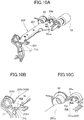
- FIG. 10A is a perspective view illustrating the roller support mechanism 200 positioned at the separation position.
- FIG. 10B is a partially enlarged view illustrating a contact portion between the first holding member 71 and the roller support mechanism 200.
- FIG. 10C is a partially enlarged view illustrating an abutment portion between the feed pressure spring 60 and the roller support frame 201.
- the roller support mechanism 200 includes the roller support frame 201 constituted by a metal plate made of a metal material, and the roller support guide 202 made of a resin material having a high sliding property.
- the roller support guide 202 serving as a resin member has a first stiffness
- the roller support frame 201 serving as a metal member has a second stiffness higher than the first stiffness.
- the roller support frame 201 and the roller support guide 202 are fastened each other with a plurality of screws 203 to 205.
- the roller support frame 201 includes a screw fastened surface 201a, to which the screws 203 to 205 are fastened and which serves as a body portion, and pivot supporting surfaces 201b and 201c which are formed on both ends of the screw fastened surface 201a and which extend perpendicular to the screw fastened surface 201a. That is, the screw fastened surface 201a extends in an axial direction AD of the feed driving shaft 59.
- the pivot supporting surface 201b which serves as a first bearing holding portion, extends from a first end portion 201e, in the axial direction AD, of the screw fastened surface 201a towards a cross direction CD which crosses the axial direction AD.
- the pivot supporting surface 201c which serves as a second bearing holding portion, extends from a second end portion 201f of the screw fastened surface 201a toward the cross direction CD.
- the pivot supporting surfaces 201b and 201c respectively have through-holes 201b1 and 201c1, through which the feed driving shaft 59 passes.
- the roller support guide 202 includes a guide surface 202a, which extends in the axial direction AD of the feed driving shaft 59 and guides the sheet S fed by the pickup roller 51.
- the roller support guide 202 also includes bearing portions 202b and 202c formed at both ends of the guide surface 202a.
- the bearing portion 202b is interposed between the through-hole 201b1 of the roller support frame 201 and the feed driving shaft 59 and slidingly supports the feed driving shaft 59
- the bearing portion 202c is interposed between the through-hole 201c1 of the roller support frame 201 and the feed driving shaft 59 and slidingly supports on the feed driving shaft 59.
- the bearing portions 202b and 202c which serves as a first bearing portion and a second bearing portion, are disposed at different positions in the axial direction AD, and supported by the pivot supporting surfaces 201b and 201c, respectively.
- the guide surface 202a and the bearing portions 202b and 202c are formed of a resin material as a one piece.
- the guide surface 202a has screw fastened portions 202a1 to 202a3, to which the screws 203 to 205 are fastened.
- the screw fastened portions 202a1 to 202a3 are concaved with respect to the guide surface 202a so that the sheet S is not caught.
- FIG. 9 is a cross-sectional view illustrating an 8A-8A cross section which is perpendicular to the axial direction AD of FIG. 8A .
- the guide surface 202a of the roller support guide 202 is disposed below the feed driving shaft 59, and partly overlapped with the feed driving shaft 59 in the sheet feed direction.
- an imaginary line VL is drawn so as to extend from a downstream edge portion 202e, in the sheet feed direction, of the guide surface 202a, the imaginary line VL lies below the feed driving shaft 59.
- the guide surface 202a is made of a metal material, the cost will increase, partly because the guide surface 202a has a complex shape.
- a resin material can achieve a desired shape, with less cost than the metal material.
- one end portion of the guide surface 202a is provided with the abutment portion 202d, which is disposed out of a sheet conveyance area and can abut against the upper edge portion 71b of the first holding member 71.
- the sheet conveyance area is a space through which the sheet fed by the pickup roller 51 passes.
- the first holding member 71 which abuts against the abutment portion 202d, is also disposed out of the sheet conveyance area in the axial direction AD of the feed driving shaft 59.
- the pickup roller 51 is disposed at a substantially center portion of the sheet conveyance area in the axial direction AD of the feed driving shaft 59.
- the feed pressure spring 60 is disposed in the vicinity of the pickup roller 51.
- the bearing portions 202b and 202c respectively, have collar portions 207b and 207c which are inserted into the through-holes 201b1 and 201c1, and flange portions 208b and 208c which extend radially along the pivot supporting surfaces 201b and 201c.
- the roller support guide 202 can be easily positioned with respect to the roller support frame 201.
- the upper edge portion 71b of the first holding member 71 abuts against the abutment portion 202d of the roller support guide 202, from the downward direction, and is in contact with the abutment portion 202d.
- the abutment portion 202d is in contact with an end portion 201d of the pivot supporting surface 201c of the roller support frame 201, on a side of the abutment portion 202d opposite to the upper edge portion 71b.
- one end portion 60a of the feed pressure spring 60 is supported on the first end portion 201e of the screw fastened surface 201a of the roller support frame 201.
- the end portion 201d of the pivot supporting surface 201c and the first end portion 201e of the screw fastened surface 201a constitute a receiving portion 400, and are disposed separately at one end side and the other end side of the roller support frame 201 in the axial direction of the feed driving shaft 59. Since a direction in which the end portion 201d receives one force and a direction in which the first end portion 201e receives another force are substantially opposite to each other, torsional stress occurs in the roller support frame 201.
- the roller support mechanism 200 is constituted by the roller support frame 201 formed of a metal material having a high stiffness, and the roller support guide 202 formed of a resin material having a high sliding property. Since the roller support frame 201 receives the urging force of the feed pressure spring 60 and the urging force of the tension coil spring 73, and the roller support guide 202 slidingly contacts with the sheet S and the feed driving shaft 59, torsional stress occurs in the roller support frame 201. However, the deformation of the roller support mechanism 200 can be reduced because the roller support frame 201 is made of a metal material having a high stiffness.
- the sheet feeding apparatus 6 needs not to be designed larger in consideration of the deformation of the roller support mechanism 200, and thus the sheet feeding apparatus 6 can be prevented from being designed larger.
- the roller support guide 202 having a high sliding property enables better sliding properties for the sheet S and the feed driving shaft 59.
- the roller support frame 201 and the roller support guide 202 are fixed to each other via the screws in the present embodiment, but the present disclosure is not limited to this.
- the holes 201b1 and 201c1 on which the roller support mechanism 200 pivots are formed in a circular shape in the figures, but the present disclosure is not limited to the circular shape as long as the holes are formed so that the bearing portions 202b and 202c of the roller support guide 202 fit the holes.
- the holes may be formed so as to have two parallel planes.
- the upper edge portion 71b of the first holding member 71 abuts against the abutment portion 202d of the roller support guide 202
- the upper edge portion 71b may directly contact the end portion 201d of the pivot supporting surface 201c of the roller support frame 201.
- the holding hook portion 1c of the second holding member 1 may directly contact the end portion 201d of the pivot supporting surface 201c of the roller support frame 201.
- the feed pressure spring 60 although the one end portion 60a contacts the roller support frame 201 for urging, the one end portion 60a may not necessarily contact the roller support frame 201 as long as the roller support frame 201 receives the urging force.
- the second embodiment is configured such that the roller support mechanism 200 of the first embodiment is achieved by another configuration.
- the same components as those of the first embodiment are omitted in the drawings, or described with the same symbols given to the drawings.
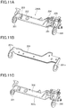
- FIG. 11B is a perspective view illustrating the roller support frame 201.
- FIG. 11C is a perspective view illustrating bearings 300 and 301, and a guide portion 302.
- FIG. 11A is a perspective view illustrating a roller support mechanism 200A in which the roller support frame 201, the bearings 300 and 301, and the guide portion 302 are combined with each other.
- the roller support mechanism 200A which serves as a swing unit, includes the roller support frame 201, the guide portion 302 which is a resin member, and the bearings 300 and 301 which serves as the first bearing portion and the second shaft bearing portion.
- the roller support frame 201 is the same as that of the first embodiment, and thus the description thereof is omitted.
- the guide portion 302 and the bearings 300 and 301 are made of a resin material having a high sliding property and have a first stiffness, and the roller support frame 201 has a second stiffness higher than the first stiffness.
- the guide portion 302 is fixed to the roller support frame 201 with the plurality of screws 203, 204, and 205, and has a guide surface 302a which guides the sheet S fed by the pickup roller 51.
- the bearings 300 and 301 are formed separately from the guide portion 302.
- the bearing 300 is interposed between the pivot supporting surface 201b of the roller support frame 201 and the feed driving shaft 59; the bearing 301 is interposed between the pivot supporting surface 201c of the roller support frame 201 and the feed driving shaft 59.
- the bearings 300 and 301 are formed, for example, so as to have one plane or two parallel planes, and formed integrally with the pivot supporting surfaces 201b and 201c of the roller support frame 201. Also in the second embodiment, the same effects as those of the first embodiment can be obtained.
- the bearings 300 and 301 may have any material other than the resin material and may be other bearings such as sintered bearings or ball rolling bearings, as long as the other bearings function as the bearings.
- the present invention is not limited to this.
- the present invention may also be applied to an ink-jet image forming apparatus that forms images on sheets by injecting ink from its nozzle.
- a sheet feeding apparatus (6) includes a sheet supporting portion (54a), a feeding portion (51), a swing unit (200) configured to swingably support the feeding portion (51) between a feed position and a separation position, a swing shaft (59) configured to swingably support the swing unit (200), an urging portion (60) configured to urge the swing unit (200) toward the feed position, and a holding portion (71) configured to hold the swing unit (200) at the separation position against an urging force of the urging portion (60).
- the swing unit (200) includes a first and second bearing portions (202b and 202c) configured to slidingly support the swing shaft (59), a metal member (201) configured to hold the first and second bearing portions (202b and 202c), and a resin member (202) including a guide surface (202a) configured to guide the sheet fed by the feeding portion (51).
Landscapes
- Engineering & Computer Science (AREA)
- Mechanical Engineering (AREA)
- Physics & Mathematics (AREA)
- General Physics & Mathematics (AREA)
- Sheets, Magazines, And Separation Thereof (AREA)
Abstract
Description
- The present invention relates to a sheet feeding apparatus for feeding sheets and an image forming apparatus including the sheet feeding apparatus.
- In general, image forming apparatuses, such as copying machines and printers, include a feed cassette which stores sheets to be fed to an image forming portion, and which is inserted to and drawn from an image forming apparatus body (hereinafter referred to as an apparatus body). In these image forming apparatuses, when the feed cassette is attached, a feed roller moves down to a feed position to feed the sheets, and abuts against a sheet in the feed cassette. The feed roller then rotates in a sheet feed direction in accordance with a feed signal, and thereby sends the sheets of the feed cassette downstream, sequentially from an uppermost one of the sheets.
- Conventionally, Japanese Patent Laid-Open No.
2015-086071 - However, the supporting member described in Japanese Patent Laid-Open No.
2015-086071 - In this case, to prevent the interference between the feed roller and the sheets of the feed cassette caused when the feed cassette is inserted and drawn, a space needs to be secured in consideration of the deformation of the supporting member. This leads to upsizing of the apparatus.
- The present invention in its first aspect provides a sheet feeding apparatus as specified in
claims 1 through 16. The present invention in its second aspect provides an image forming apparatus as specified in claim 17. - Further features of the present invention will become apparent from the following description of exemplary embodiments with reference to the attached drawings.
-
-
FIG. 1 is an overall schematic diagram of a printer of a first embodiment. -
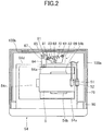
FIG. 2 is a plan view illustrating a feed cassette and a drawing unit. -
FIG. 3A is a perspective view illustrating a roller support mechanism and each roller. -
FIG. 3B is a cross-sectional view illustrating a state where a pickup roller abuts against a top face of a sheet. -
FIG. 4A is a perspective view illustrating the roller support mechanism and a holding mechanism. -
FIG. 4B is a perspective view illustrating a first holding member and a second holding member. -
FIG. 5A is a perspective view illustrating the holding mechanism in a state where the pickup roller is positioned at a standby position. -
FIG. 5B is a perspective view illustrating a configuration of a vicinity of a guided portion of the feed cassette. -
FIG. 6A is a side view illustrating the second holding member. -
FIG. 6B is a perspective view illustrating the first holding member and the second holding member. -
FIG. 7A is a perspective view illustrating the first holding member in a state where the pickup roller is positioned at a feed position. -
FIG. 7B is a side view illustrating the second holding member. -
FIG. 8A is a perspective view illustrating the roller support mechanism. -
FIG. 8B is a perspective view illustrating a roller support frame. -
FIG. 8C is a perspective view illustrating a roller support guide. -
FIG. 9 is a cross-sectional view taken along aline 8A-8A ofFIG. 8A . -
FIG. 10A is a perspective view illustrating the roller support mechanism. -
FIG. 10B is a partially enlarged view illustrating a contact portion between the first holding member and the roller support mechanism. -
FIG. 10C is a partially enlarged view illustrating an abutment portion between the feed pressure spring and the roller support frame. -
FIG. 11A is a perspective view illustrating a roller support mechanism of a second embodiment. -
FIG. 11B is a perspective view illustrating the roller support frame. -
FIG. 11C is a perspective view illustrating a guide portion and bearings. - First, a first embodiment of the present invention will be described. A
printer 100 of the first embodiment, which serves as an image forming apparatus, is an electrophotographic laser-beam printer. As illustrated inFIG. 1 , theprinter 100 includes anapparatus body 100a, which includes asheet feeding apparatus 6 and animage forming portion 20. Theimage forming portion 20 includes an intermediatetransfer belt unit 10, anexposure apparatus 7, andprocess cartridges 17a to 17d. - The
sheet feeding apparatus 6 is provided with afeed cassette 54, which stores sheet S and serves as a drawer portion. Thefeed cassette 54 holds a sheet-stackingplate 54a, on which the sheet S is stacked and which can raise and lower the sheet S. The sheet-stackingplate 54a serves as a sheet supporting portion. Theprocess cartridges 17a to 17d are disposed along anintermediate transfer belt 11 of the intermediatetransfer belt unit 10, and includephotosensitive drums - The
process cartridges 17a to 17d are configured to form toner images of yellow, magenta, cyan, and black, respectively in this order. Each of thephotosensitive drums FIG. 1 . Theexposure apparatus 7 irradiates thephotosensitive drums - The
photosensitive drums exposure apparatus 7 form electrostatic latent images on the surfaces of thephotosensitive drums photosensitive drums intermediate transfer belt 11. - The intermediate
transfer belt unit 10 includes theintermediate transfer belt 11, which is wound and stretched around a drivingroller 12, a drivenroller 14, and atension roller 16, which are disposed so as to have a predetermined positional relationship. Asecondary transfer roller 13 is disposed at a position which faces the drivingroller 12. Thesecondary transfer roller 13 holds theintermediate transfer belt 11 between thesecondary transfer roller 13 and the drivingroller 12. Thesecondary transfer roller 13 and theintermediate transfer belt 11 form a transfer nip N, which transfers the toner images onto the sheet. - The
sheet feeding apparatus 6 includes apickup roller 51 which serves as a feeding portion, afeed roller 52, and aretard roller 53 which is in pressure contact with thefeed roller 52. The sheet S fed by thepickup roller 51 is sent, one by one, by thefeed roller 52 and theretard roller 53, and conveyed to aregistration roller pair 22 constituted byconveyance rollers retard roller 53 is driven by thefeed roller 52, when a limit value of a torque limiter is exceeded. Theretard roller 53 is applied with a driving force toward a direction opposite to a sheet conveyance direction, but the driving force may not be applied. The sheet S is once stopped at theregistration roller pair 22 in a state where the sheet S abuts against a nip of theregistration roller pair 22. After that, the sheet S is sent into the transfer nip N at a predetermined timing by theregistration roller pair 22. - The transfer nip N is applied with transfer bias via the
secondary transfer roller 13, and thereby secondary transfer of the four colors of toner image formed on the intermediate transfer belt is performed on the sheet S, which is sent from thesheet feeding apparatus 6 and conveyed by theregistration roller pair 22. In addition, abelt cleaning apparatus 33 is disposed at a position which faces thetension roller 16, so as to abut against the surface of theintermediate transfer belt 11. - Above the transfer nip N, a fixing
apparatus 15 is disposed. The fixingapparatus 15 includes a fixingroller 15a and apressure roller 15b. The sheet S, onto which the toner images have been transferred, is conveyed to a fixing nip portion between the fixingroller 15a and thepressure roller 15b, and is heated and pressurized by the fixingroller 15a and thepressure roller 15b. Thus, the transferred toner images are fixed on the surface of the sheet S. After the toner images are fixed on the sheet S by the fixingapparatus 15, the sheet S is discharged onto adischarge tray 19 via adischarge roller pair 18. - Next, the
feed cassette 54 will be described. As illustrated inFIG. 2 , thefeed cassette 54 is configured to be attached to and drawn from theapparatus body 100a. Thefeed cassette 54 includes the sheet-stackingplate 54a on which the sheet S is stacked,side regulation members 54b which regulate side edges of the sheet S stacked on the sheet-stackingplate 54a, and a trailingedge regulation member 54c which regulates a trailing edge of the sheet S. Thefeed cassette 54 is supported by guide rails 21 (seeFIG. 6B ) so that thefeed cassette 54 can move between an attachment position and a drawn position. The attachment position is a position for feeding the sheet, and the drawn position is a position to which thefeed cassette 54 is drawn out from the attachment position. - The
feed cassette 54 is drawn from theapparatus body 100a to refill thefeed cassette 54 with the sheet. Thus, thefeed cassette 54 may be restricted from drawing by a regulation portion (not illustrated), during the drawing, at a position at which thefeed cassette 54 can be refilled with the sheet; or may be drawn out of theapparatus body 100a. In addition, thefeed cassette 54 is configured to be drawn toward a direction perpendicular to the feed direction in which thepickup roller 51 feeds the sheet, that is, toward a frontward direction on the sheet ofFIG. 1 . - As illustrated in
FIG. 2 , thesheet feeding apparatus 6 is provided with adrawing unit 66, which is configured to draw thefeed cassette 54 into theapparatus body 100a. On a back-side side wall 54d of thefeed cassette 54, aswing arm 64 is supported so that theswing arm 64 can swing on ashaft 64a which serves as a supporting point. Theswing arm 64 has aswing pin 65 at a leading end portion of theswing arm 64. Thedrawing unit 66 is formed on a back-sideinner wall surface 100b of theapparatus body 100a. Thedrawing unit 66 includes adrawing unit base 69 and adrawing arm 68. Thedrawing arm 68 has adrawing hook 67 at a leading end of thedrawing arm 68, and is supported so that thedrawing arm 68 can pivot on a fulcrum 70 disposed on thedrawing unit base 69. - The
drawing hook 67 of thedrawing arm 68 is provided with aconcave portion 91, which locks theswing pin 65 of theswing arm 64. In addition, anarm pin 81 is provided between the drawinghook 67 of thedrawing arm 68 and thefulcrum 70; abase pin 82 is provided on thedrawing unit base 69; and anextension spring 83 is provided such that one end of theextension spring 83 is locked by thearm pin 81 and the other end is locked by thebase pin 82. Theextension spring 83 urges thedrawing arm 68 so that thedrawing arm 68 pivots around thefulcrum 70. Theextension spring 83 and thedrawing arm 68 form a toggle mechanism, and the urging direction of thedrawing arm 68 by theextension spring 83 is changed when thedrawing arm 68 is positioned at a predetermined pivot position. - Specifically, in a case where the
feed cassette 54 is to be drawn out, while theconcave portion 91 locks theswing pin 65, thedrawing arm 68 pivots counterclockwise, i.e., drawing direction, around thefulcrum 70 against an urging force ofextension spring 83 from a position illustrated inFIG. 2 . After that, when thefeed cassette 54 is further drawn, thedrawing arm 68 pivots until the lock of theswing pin 65 and theconcave portion 91 is released. Then, thedrawing arm 68 is urged counterclockwise by theextension spring 83, and is positioned at a position at which theswing pin 65 is to be received by a stopper (not illustrated). - When the
feed cassette 54 is to be attached to theapparatus body 100a, thedrawing arm 68 is positioned at a position at which theswing pin 65 of theswing arm 64 is capable of entering theconcave portion 91 of thedrawing hook 67. Thus, when thefeed cassette 54 is inserted into theapparatus body 100a, theswing pin 65 enters theconcave portion 91 of thedrawing hook 67. After this, when thefeed cassette 54 is further pushed, thedrawing arm 68 is pushed backward against the urging force of theextension spring 83, via theswing pin 65 and thedrawing hook 67. - With this operation, the
drawing arm 68 pivots clockwise around thefulcrum 70 against theextension spring 83. After pivoting to a predetermined position, an urging force by theextension spring 83 is additionally applied to thedrawing arm 68, and thereby thedrawing arm 68 pivots clockwise. As a result, thefeed cassette 54 is attached to theapparatus body 100a by theextension spring 83, via thedrawing arm 68. - The
feed cassette 54 is provided with astopper 90. Thus, when thefeed cassette 54 is attached to theapparatus body 100a, thefeed cassette 54 abuts against abody frame 79 of theapparatus body 100a, and thereby thefeed cassette 54 is positioned with respect to theapparatus body 100a. That is, when thefeed cassette 54 is drawn into theapparatus body 100a by thedrawing unit 66, thestopper 90 of thefeed cassette 54 abuts against thebody frame 79, so that thefeed cassette 54 is stopped at the attachment position. With thefeed cassette 54 positioned at the attachment position, the sheet can be fed from thefeed cassette 54 by thepickup roller 51. - Next, a detailed configuration of the
sheet feeding apparatus 6 will be described. As illustrated inFIG. 3A , thesheet feeding apparatus 6 includes afeed frame 57, which is fixed on theapparatus body 100a (seeFIG. 1 ) and by which thefeed roller 52, theretard roller 53, and theconveyance roller 55a are supported. Specifically, as illustrated inFIG. 4A , thefeed roller 52 is fixed to an end portion of afeed driving shaft 59, which is made of metal and connected to a motor M. Thepickup roller 51 is attached to ashaft 51a which is rotatably disposed in aroller support mechanism 200. Theroller support mechanism 200 is swingably supported by thefeed driving shaft 59. Theshaft 51a is disposed parallel to thefeed driving shaft 59. Thefeed driving shaft 59 and theshaft 51a are coupled with each other via a gear train G. - With this configuration, the driving force from the motor M is transmitted to the
feed driving shaft 59, and to theshaft 51a via the gear train G, so that thepickup roller 51 rotates. Thepickup roller 51 abuts against the top face of the sheet S stacked on the sheet-stackingplate 54a, and rotates with the rotation of theshaft 51a, so that the sheet is sent. With this operation, thepickup roller 51 sends an uppermost sheet downstream in the sheet feed direction (direction indicated by an arrow A inFIG. 3A ). - The
pickup roller 51 is configured so that it can move between a feed position and a standby position, depending on the attachment or drawing operation of thefeed cassette 54. The feed position is a position at which thepickup roller 51 abuts against the sheet S of thefeed cassette 54 and feeds the sheet S (seeFIG. 3B ). The standby position is a position at which thepickup roller 51 is separated from the sheet S and waits (seeFIG. 5A ). Thepickup roller 51 moves from the feed position to the standby position, with theroller support mechanism 200 being raised. That is, theroller support mechanism 200, which serves as a swing unit, swingably supports thepickup roller 51 between a feed position, at which thepickup roller 51 can feed the sheet, and a separation position at which thepickup roller 51 is separated from the sheet. - As illustrated in
FIG. 4A , thesheet feeding apparatus 6 includes afeed pressure spring 60, which serves as an urging portion and a first urging portion. Thefeed pressure spring 60 urges theroller support mechanism 200 toward the feed position so that thepickup roller 51 is in pressure contact with the top face of the sheet S stacked on the sheet-stackingplate 54a. Thefeed pressure spring 60 is constituted by a torsion coil spring, which loosely fits thefeed driving shaft 59. One end of the torsion coil spring is connected to theroller support mechanism 200, and the other end is connected to a frame of theapparatus body 100a. Theroller support mechanism 200 is swingably supported by thefeed driving shaft 59 which serves as a swing shaft, and rotatably supports theshaft 51a of thepickup roller 51. - As illustrated in
FIGS. 4A and5A , thesheet feeding apparatus 6 is provided with aholding mechanism 30, which holds theroller support mechanism 200 at the separation position so that thepickup roller 51 is positioned at the standby position. The holdingmechanism 30 releases the holding of theroller support mechanism 200 when thefeed cassette 54 is attached to the apparatus body. As illustrated inFIG. 4B , the holdingmechanism 30 includes a first holdingmember 71 and asecond holding member 1, which can hold theroller support mechanism 200 at the separation position in a state where thefeed cassette 54 is positioned at the drawn position. Thesecond holding member 1 is disposed on the back side with respect to the first holdingmember 71 in an attachment direction of thefeed cassette 54. In addition, the first holdingmember 71 is disposed at a position different from a position of thefeed pressure spring 60 in an axial direction AD of thefeed driving shaft 59. More specifically, thefeed pressure spring 60 contacts with theroller support mechanism 200 at a first position, and the first holdingmember 71 contacts with theroller support mechanism 200 at a second position different from the first position in the axial direction AD. - The first holding
member 71 loosely fits thefeed driving shaft 59, and can pivot between a holding position and a non-holding position. The holding position is a position at which the first holdingmember 71 holds theroller support mechanism 200 at the separation position. The non-holding position is a position at which the first holdingmember 71 is separated from theroller support mechanism 200 and thus does not hold theroller support mechanism 200. When the first holdingmember 71 is positioned at the holding position, thepickup roller 51 is held at the standby position. When the first holdingmember 71 releases the holding of theroller support mechanism 200, thepickup roller 51 can be moved to the feed position by thefeed pressure spring 60. Similarly, when the second holdingmember 1 holds theroller support mechanism 200 at the separation position, thepickup roller 51 is held at the standby position. When the second holdingmember 1 releases the holding of theroller support mechanism 200, thepickup roller 51 can be moved to the feed position by thefeed pressure spring 60. - As illustrated in
FIGS. 4A, 4B , and5A , the first holdingmember 71, which serves as a holding portion, is formed like a plate, and can pivot between the holding position and the non-holding position, in a direction perpendicular to the attachment direction in which thefeed cassette 54 is attached to the apparatus body. In addition, the first holdingmember 71 is urged toward a direction indicated by an arrow Y inFIG. 5A , by atension coil spring 73 which is disposed between the first holdingmember 71 and thefeed frame 57 and which serves as a second urging portion. The first holdingmember 71 has anupper edge portion 71b which serves as a pressing portion. In a state where thefeed cassette 54 is positioned at the drawn position, theupper edge portion 71b abuts against anabutment portion 202d of theroller support mechanism 200 from a downward direction, and holds theroller support mechanism 200 at the separation position. - The first holding
member 71 also has a pressedportion 71a formed in a lower portion of the first holdingmember 71. When the pressedportion 71a is pushed by thefeed cassette 54 which is being attached to theapparatus body 100a, the first holdingmember 71 rotates toward a direction opposite to the direction indicated by the arrow Y inFIG. 5A , against the urging force of thetension coil spring 73. With this operation, theupper edge portion 71b of the first holdingmember 71 is separated from theroller support mechanism 200 and releases the holding of theroller support mechanism 200, and thus thepickup roller 51 abuts against the top face of the sheet of thefeed cassette 54 at a predetermined feed pressure, due to the urging force of thefeed pressure spring 60. - The
second holding member 1, which serves as a second holding portion, is configured to pivot with the attachment of thefeed cassette 54. Next, a configuration of the second holdingmember 1 will be described. As illustrated inFIGS. 4B and5A , the second holdingmember 1 is constituted by a resin spring which is made from synthetic resin, and is attached to thefeed frame 57 so that the second holdingmember 1 can pivot around apivot supporting shaft 4. Thepivot supporting shaft 4 extends in a direction perpendicular to the insertion-and-removal direction of thefeed cassette 54. Thesecond holding member 1 includes abody portion 1a, which is disposed so as to extend in a vertical direction, and anarm portion 1b, which is formed like an arm and elongated upstream in the sheet feed direction and which engages with aside wall 57a of thefeed frame 57. - The
body portion 1a has a hook-likeholding hook portion 1c formed on the upper end of thebody portion 1a. As illustrated inFIGS. 5A and6A , the holdinghook portion 1c protrudes from theside wall 57a of thefeed frame 57 due to a resin spring property by thearm portion 1b. In addition, the second holdingmember 1 is positioned at a position illustrated inFIG. 6A , by a rotation stopper (not illustrated). Thus, when thebody portion 1a is pushed downstream (direction indicated by an arrow E inFIG. 6A ) in the attachment direction of thefeed cassette 54, the second holdingmember 1 is retracted into the interior of theside wall 57a. In a state where the holdinghook portion 1c protrudes from theside wall 57a, the holdinghook portion 1c abuts from below against theabutment portion 202d, which is formed on theroller support mechanism 200 and protrudes from the same, and thus holds theroller support mechanism 200 at the separation position. - Next, a configuration on the
feed cassette 54 side of theholding mechanism 30 will be described.FIG. 5B illustrates a portion of thefeed cassette 54, located downstream in the attachment direction of thefeed cassette 54 and on one side (that is, the back side of a right portion ofFIG. 1 ). Thefeed cassette 54 is configured to be attached to and drawn from theapparatus body 100a in the insertion-and-drawing direction, which is a front-back direction ofFIG. 1 . Thefeed cassette 54 is provided so as to be inserted into and drawn from theapparatus body 100a, and includes guidedportions 2 on both right and left sides of thefeed cassette 54. The guidedportions 2 are guided by the guide rails 21 (seeFIG. 6B ). The guidedportions 2 haveguide rollers 5 disposed on top portions of the leading ends of the guidedportions 2. Theguide rollers 5 roll in the guide rails 21, and smooth the attachment/removal of thefeed cassette 54 to/from theapparatus body 100a. - The
feed cassette 54 is provided with asecond release portion 3, which has a flat surface perpendicular to the attachment direction of thefeed cassette 54. Thesecond release portion 3 is used to push the second holdingmember 1 disposed on theapparatus body 100a, against the urging force of the second holdingmember 1. Thesecond release portion 3 is formed to pivot the second holdingmember 1 toward a release direction and release the holding of theroller support mechanism 200 when the attachment of thefeed cassette 54 to theapparatus body 100a is completed. - Furthermore, the
feed cassette 54 is provided with afirst release portion 74 which has asloping surface 74a. Thesloping surface 74a slidingly contacts the pressedportion 71a of the first holdingmember 71, and pivots the first holdingmember 71 toward the counterclockwise direction ofFIG. 5A , against the elastic urging force of thetension coil spring 73 which is an elastic member. Since the insertion-and-removal direction of thefeed cassette 54 and the pivot direction of the first holdingmember 71 are perpendicular to each other, thesloping surface 74a is sloping such that thesloping surface 74a is further upstream in the attachment direction as thesloping surface 74a extends downstream in the sheet feed direction. Thesloping surface 74a of thefirst release portion 74, which serves as a pressing surface, pivots the first holdingmember 71 from the holding position toward the non-holding position, with the attachment operation of thefeed cassette 54. The position of thefirst release portion 74 and the position thesecond release portion 3 of thefeed cassette 54 are shifted from each other in the attachment direction of thefeed cassette 54. - Next, an operation of the
holding mechanism 30 performed with the attachment and drawing operation of thefeed cassette 54 will be described in detail. First, in a state where thefeed cassette 54 is drawn from theapparatus body 100a, the first holdingmember 71 does not touch thefirst release portion 74 of thefeed cassette 54. In this time, the first holdingmember 71 is positioned at the holding position by thetension coil spring 73 urging the first holdingmember 71, as illustrated inFIG. 5A . In addition, theupper edge portion 71b of the first holdingmember 71 is pushing up theabutment portion 202d of theroller support mechanism 200 against the urging force of thefeed pressure spring 60, and thus the first holdingmember 71 holds theroller support mechanism 200 at the separation position. In this time, thepickup roller 51 is positioned at the standby position at which thepickup roller 51 does not touch thefeed cassette 54 and the sheet stored in thefeed cassette 54. - Also, the second holding
member 1 does not touch thesecond release portion 3 of thefeed cassette 54, and the holdinghook portion 1c protrudes downstream in the drawing direction, from theside wall 57a of thefeed frame 57, due to the resin spring property by thearm portion 1b, as illustrated inFIGS. 5A and6A . When a user tries to attach thefeed cassette 54 to theapparatus body 100a, thesloping surface 74a of thefirst release portion 74 first abuts against the pressedportion 71a of the first holdingmember 71. Then, thesloping surface 74a pivots the first holdingmember 71 from the holding position toward the non-holding position against the urging force of thetension coil spring 73, with the attachment operation of thefeed cassette 54. - With this operation, the first holding
member 71 is positioned at the non-holding position as illustrated inFIG. 6B , but thesecond release portion 3 of thefeed cassette 54 still does not touch the second holdingmember 1 in this time. Thus, although the holding of theroller support mechanism 200 by the first holdingmember 71 is released, theroller support mechanism 200 remains held at the separation position by the second holdingmember 1. In this time, theupper edge portion 71b of the first holdingmember 71 is separated from theabutment portion 202d of theroller support mechanism 200. - When the user further pushes the
feed cassette 54 toward theapparatus body 100a, thesecond release portion 3 abuts against thebody portion 1a of the second holdingmember 1, and pushes thebody portion 1a toward the direction indicated by the arrow E inFIG. 6A . Then, when thefeed cassette 54 abuts against the stopper 90 (seeFIG. 2 ) and is positioned at the attachment position, the second holdingmember 1 is retracted into the interior of theside wall 57a as illustrated inFIG. 7B , and the holding of theroller support mechanism 200 by the holdinghook portion 1c is released. With this operation, the holding of theroller support mechanism 200 by the first holdingmember 71 and the second holdingmember 1 is released as illustrated inFIG. 7A , and theroller support mechanism 200 is swung to the feed position by the urging force of thefeed pressure spring 60. - Next, an operation of the
holding mechanism 30 performed when thefeed cassette 54 is drawn from theapparatus body 100a will be described. In a state where thefeed cassette 54 is attached to theapparatus body 100a, the holdinghook portion 1c of the second holdingmember 1 is in contact with a side surface of theabutment portion 202d of theroller support mechanism 200, and the second holdingmember 1 is stored in theside wall 57a. When thefeed cassette 54 is drawn from theapparatus body 100a by a user, the first holdingmember 71 is pivoted along thesloping surface 74a of thefirst release portion 74 toward the direction indicated by the arrow Y inFIG. 5A , by the urging force of thetension coil spring 73. With this operation, theupper edge portion 71b of the first holdingmember 71 pushes up theabutment portion 202d of theroller support mechanism 200 from below. Here, the urging force of thetension coil spring 73 is larger than that of thefeed pressure spring 60. - When the
upper edge portion 71b of the first holdingmember 71 pushes up theabutment portion 202d of theroller support mechanism 200 to the holding position, the holdinghook portion 1c of the second holdingmember 1 moves to a space located below theabutment portion 202d of theroller support mechanism 200. With this operation, theroller support mechanism 200 is held at the separation position by the first holdingmember 71 and the second holdingmember 1, and thepickup roller 51 can be held at the standby position. Thus, the first holdingmember 71 has a function that pushes up theroller support mechanism 200 to move theroller support mechanism 200 to the separation position, and to move thepickup roller 51 to the standby position. Thesecond holding member 1 has a function that releases the holding of theroller support mechanism 200 when thefeed cassette 54 is positioned at the attachment position as illustrated inFIG. 7B , and thereby causes thepickup roller 51 to move down to the feed position. -
FIG. 8A is a perspective view illustrating a state where aroller support frame 201 and aroller support guide 202, which constitute theroller support mechanism 200, are combined with each other.FIG. 8B is a perspective view illustrating theroller support frame 201.FIG. 8C is a perspective view illustrating theroller support guide 202.FIG. 10A is a perspective view illustrating theroller support mechanism 200 positioned at the separation position.FIG. 10B is a partially enlarged view illustrating a contact portion between the first holdingmember 71 and theroller support mechanism 200.FIG. 10C is a partially enlarged view illustrating an abutment portion between thefeed pressure spring 60 and theroller support frame 201. - As illustrated in
FIG. 8A , theroller support mechanism 200 includes theroller support frame 201 constituted by a metal plate made of a metal material, and theroller support guide 202 made of a resin material having a high sliding property. Theroller support guide 202 serving as a resin member has a first stiffness, and the roller support frame 201serving as a metal member has a second stiffness higher than the first stiffness. Theroller support frame 201 and theroller support guide 202 are fastened each other with a plurality ofscrews 203 to 205. - As illustrated in
FIG. 8B , theroller support frame 201 includes a screw fastenedsurface 201a, to which thescrews 203 to 205 are fastened and which serves as a body portion, and pivot supportingsurfaces surface 201a and which extend perpendicular to the screw fastenedsurface 201a. That is, the screw fastenedsurface 201a extends in an axial direction AD of thefeed driving shaft 59. Thepivot supporting surface 201b, which serves as a first bearing holding portion, extends from afirst end portion 201e, in the axial direction AD, of the screw fastenedsurface 201a towards a cross direction CD which crosses the axial direction AD. Thepivot supporting surface 201c, which serves as a second bearing holding portion, extends from asecond end portion 201f of the screw fastenedsurface 201a toward the cross direction CD. Thepivot supporting surfaces feed driving shaft 59 passes. - As illustrated in
FIG. 8C , theroller support guide 202 includes aguide surface 202a, which extends in the axial direction AD of thefeed driving shaft 59 and guides the sheet S fed by thepickup roller 51. Theroller support guide 202 also includes bearingportions guide surface 202a. The bearingportion 202b is interposed between the through-hole 201b1 of theroller support frame 201 and thefeed driving shaft 59 and slidingly supports thefeed driving shaft 59, the bearingportion 202c is interposed between the through-hole 201c1 of theroller support frame 201 and thefeed driving shaft 59 and slidingly supports on thefeed driving shaft 59. The bearingportions pivot supporting surfaces guide surface 202a and the bearingportions guide surface 202a has screw fastened portions 202a1 to 202a3, to which thescrews 203 to 205 are fastened. The screw fastened portions 202a1 to 202a3 are concaved with respect to theguide surface 202a so that the sheet S is not caught. -
FIG. 9 is a cross-sectional view illustrating an 8A-8A cross section which is perpendicular to the axial direction AD ofFIG. 8A . As illustrated inFIG. 9 , theguide surface 202a of theroller support guide 202 is disposed below thefeed driving shaft 59, and partly overlapped with thefeed driving shaft 59 in the sheet feed direction. In addition, if an imaginary line VL is drawn so as to extend from adownstream edge portion 202e, in the sheet feed direction, of theguide surface 202a, the imaginary line VL lies below thefeed driving shaft 59. With theguide surface 202a formed in this manner, even when a curled sheet by thepickup roller 51 is fed, the sheet can be prevented from touching thefeed driving shaft 59. With this configuration, the sheet can be prevented from entering a space between theguide surface 202a and thefeed driving shaft 59, and thus from being jammed. - If such the
guide surface 202a is made of a metal material, the cost will increase, partly because theguide surface 202a has a complex shape. In contrast, a resin material can achieve a desired shape, with less cost than the metal material. Thus, in the present embodiment, a problem in which theroller support mechanism 200 is deformed is resolved by theroller support frame 201 made of a metal material, and a problem in which the sheet is not properly guided is resolved by theroller support guide 202 made of a resin material. - As illustrated in
FIG. 8C , one end portion of theguide surface 202a is provided with theabutment portion 202d, which is disposed out of a sheet conveyance area and can abut against theupper edge portion 71b of the first holdingmember 71. The sheet conveyance area is a space through which the sheet fed by thepickup roller 51 passes. As illustrated inFIG. 4A , the first holdingmember 71, which abuts against theabutment portion 202d, is also disposed out of the sheet conveyance area in the axial direction AD of thefeed driving shaft 59. On the other hand, thepickup roller 51 is disposed at a substantially center portion of the sheet conveyance area in the axial direction AD of thefeed driving shaft 59. Thefeed pressure spring 60 is disposed in the vicinity of thepickup roller 51. - The bearing
portions collar portions flange portions pivot supporting surfaces collar portions flange portions roller support guide 202 can be easily positioned with respect to theroller support frame 201. - As illustrated in
FIGS. 10A and 10B , in a state where theroller support mechanism 200 is positioned at the separation position, theupper edge portion 71b of the first holdingmember 71 abuts against theabutment portion 202d of theroller support guide 202, from the downward direction, and is in contact with theabutment portion 202d. In addition, theabutment portion 202d is in contact with anend portion 201d of thepivot supporting surface 201c of theroller support frame 201, on a side of theabutment portion 202d opposite to theupper edge portion 71b. With this configuration, a force from the first holdingmember 71 which is urged upward by thetension coil spring 73 can be received by theend portion 201d of theroller support frame 201, which serves as a contact portion, via theabutment portion 202d. That is, theend portion 201d is in contact with a first surface, of theabutment portion 202d, opposite to a second surface on which theupper edge portion 71b presses theabutment portion 202d in the swing direction of theroller support mechanism 200. - In addition, as illustrated in
FIG. 10C , oneend portion 60a of thefeed pressure spring 60 is supported on thefirst end portion 201e of the screw fastenedsurface 201a of theroller support frame 201. With this configuration, the urging force of thefeed pressure spring 60 can be received by theroller support frame 201. Theend portion 201d of thepivot supporting surface 201c and thefirst end portion 201e of the screw fastenedsurface 201a constitute a receivingportion 400, and are disposed separately at one end side and the other end side of theroller support frame 201 in the axial direction of thefeed driving shaft 59. Since a direction in which theend portion 201d receives one force and a direction in which thefirst end portion 201e receives another force are substantially opposite to each other, torsional stress occurs in theroller support frame 201. - As described above, in the present embodiment, the
roller support mechanism 200 is constituted by theroller support frame 201 formed of a metal material having a high stiffness, and theroller support guide 202 formed of a resin material having a high sliding property. Since theroller support frame 201 receives the urging force of thefeed pressure spring 60 and the urging force of thetension coil spring 73, and theroller support guide 202 slidingly contacts with the sheet S and thefeed driving shaft 59, torsional stress occurs in theroller support frame 201. However, the deformation of theroller support mechanism 200 can be reduced because theroller support frame 201 is made of a metal material having a high stiffness. Furthermore, thesheet feeding apparatus 6 needs not to be designed larger in consideration of the deformation of theroller support mechanism 200, and thus thesheet feeding apparatus 6 can be prevented from being designed larger. In addition, theroller support guide 202 having a high sliding property enables better sliding properties for the sheet S and thefeed driving shaft 59. - The
roller support frame 201 and theroller support guide 202 are fixed to each other via the screws in the present embodiment, but the present disclosure is not limited to this. In addition, the holes 201b1 and 201c1 on which theroller support mechanism 200 pivots are formed in a circular shape in the figures, but the present disclosure is not limited to the circular shape as long as the holes are formed so that the bearingportions roller support guide 202 fit the holes. For example, the holes may be formed so as to have two parallel planes. - In addition, although the
upper edge portion 71b of the first holdingmember 71 abuts against theabutment portion 202d of theroller support guide 202, theupper edge portion 71b may directly contact theend portion 201d of thepivot supporting surface 201c of theroller support frame 201. Similarly, the holdinghook portion 1c of the second holdingmember 1 may directly contact theend portion 201d of thepivot supporting surface 201c of theroller support frame 201. Regarding thefeed pressure spring 60, although the oneend portion 60a contacts theroller support frame 201 for urging, the oneend portion 60a may not necessarily contact theroller support frame 201 as long as theroller support frame 201 receives the urging force. - Next, a second embodiment of the present invention will be described. The second embodiment is configured such that the
roller support mechanism 200 of the first embodiment is achieved by another configuration. Thus, the same components as those of the first embodiment are omitted in the drawings, or described with the same symbols given to the drawings. -
FIG. 11B is a perspective view illustrating theroller support frame 201.FIG. 11C is a perspectiveview illustrating bearings guide portion 302.FIG. 11A is a perspective view illustrating aroller support mechanism 200A in which theroller support frame 201, thebearings guide portion 302 are combined with each other. As illustrated inFIG. 11A , theroller support mechanism 200A, which serves as a swing unit, includes theroller support frame 201, theguide portion 302 which is a resin member, and thebearings roller support frame 201 is the same as that of the first embodiment, and thus the description thereof is omitted. Theguide portion 302 and thebearings roller support frame 201 has a second stiffness higher than the first stiffness. Theguide portion 302 is fixed to theroller support frame 201 with the plurality ofscrews guide surface 302a which guides the sheet S fed by thepickup roller 51. - The
bearings guide portion 302. Thebearing 300 is interposed between thepivot supporting surface 201b of theroller support frame 201 and thefeed driving shaft 59; thebearing 301 is interposed between thepivot supporting surface 201c of theroller support frame 201 and thefeed driving shaft 59. Thebearings pivot supporting surfaces roller support frame 201. Also in the second embodiment, the same effects as those of the first embodiment can be obtained. - The
bearings - Also, although the description is made using the
electrophotographic printer 100 in any of the embodiments describe above, the present invention is not limited to this. For example, the present invention may also be applied to an ink-jet image forming apparatus that forms images on sheets by injecting ink from its nozzle. - While the present invention has been described with reference to exemplary embodiments, it is to be understood that the invention is not limited to the disclosed exemplary embodiments. The scope of the following claims is to be accorded the broadest interpretation so as to encompass all such modifications and equivalent structures and functions.
- A sheet feeding apparatus (6) includes a sheet supporting portion (54a), a feeding portion (51), a swing unit (200) configured to swingably support the feeding portion (51) between a feed position and a separation position, a swing shaft (59) configured to swingably support the swing unit (200), an urging portion (60) configured to urge the swing unit (200) toward the feed position, and a holding portion (71) configured to hold the swing unit (200) at the separation position against an urging force of the urging portion (60). The swing unit (200) includes a first and second bearing portions (202b and 202c) configured to slidingly support the swing shaft (59), a metal member (201) configured to hold the first and second bearing portions (202b and 202c), and a resin member (202) including a guide surface (202a) configured to guide the sheet fed by the feeding portion (51).
Claims (17)
- A sheet feeding apparatus (6) comprising:a sheet supporting portion (54a) configured to support a sheet;a feeding portion (51) configured to feed the sheet supported by the sheet supporting portion (54a);a swing unit (200) configured to swingably support the feeding portion (51) between a feed position and a separation position, the feed position being a position at which the feeding portion (51) abuts against the sheet supported by the sheet supporting portion (54a) and feed the sheet, the separation position being a position at which the feeding portion (51) is separated from the sheet supported by the sheet supporting portion (54a);a swing shaft (59) configured to swingably support the swing unit (200);an urging portion (60) configured to contact with the swing unit (200) at a first position so as to urge the swing unit (200) toward the feed position; anda holding portion (71) configured to contact with the swing unit (200) at a second position so as to hold the swing unit (200) at the separation position against an urging force of the urging portion (60), the second position being different from the first position in an axial direction (AD) of the swing shaft (59),wherein the swing unit (200) comprises:a first bearing portion (202b) configured to slidingly support the swing shaft (59);a second bearing portion (202c) disposed offset to the first bearing portion (202b) and configured to slidingly support the swing shaft (59);a metal member (201) configured to hold the first bearing portion (202b) and the second bearing portion (202c); anda resin member (202) having a guide surface (202a) configured to guide the sheet fed by the feeding portion (51).
- The sheet feeding apparatus (6) according to claim 1, wherein the metal member (201) comprises:a body portion (201a) which extends in the axial direction (AD), and to which the resin member (202) is attached;a first bearing holding portion (201b) that extends from a first end portion (201e), in the axial direction (AD), of the body portion (201a) toward a cross direction which crosses the axial direction (AD) and that holds the first bearing portion (202b); anda second bearing holding portion (201c) that extends from a second end portion (201f), in the axial direction (AD), of the body portion (201a) toward the cross direction and that holds the second bearing portion (202c).
- The sheet feeding apparatus (6) according to claim 1 or 2, wherein the metal member (201) receives the urging force of the urging portion (60) and a force from the holding portion (71) at positions different from each other in the axial direction (AD).
- The sheet feeding apparatus (6) according to claim 3, the metal member (201) is configured to abut against the urging portion (60).
- The sheet feeding apparatus (6) according to claim 3 or 4, wherein the resin member (202) comprises an abutment portion (202d) configured to abut against the holding portion (71),
wherein the holding portion (71) comprises a pressing portion (71b) configured to press the abutment portion (202d) against the urging force of the urging portion (60), and
wherein the metal member (201) comprises a contact portion (201d) that is in contact with a first surface, of the abutment portion (202d), opposite to a second surface of the abutment portion (202d) in a swing direction of the swing unit (200), the second surface being pressed by the pressing portion (71b). - The sheet feeding apparatus (6) according to claim 5, wherein the contact portion (201d) is disposed on a first side of the metal member (201) in the axial direction (AD), and
wherein the metal member (201) supports the urging portion (60) on a second side, of the metal member (201), opposite to the first side in the axial direction (AD). - The sheet feeding apparatus (6) according to any one of claims 1 through 6, wherein the guide surface (202a) is disposed below the swing shaft (59), and
wherein at least a part of the guide surface (202a) overlaps with the swing shaft (59) in a sheet feed direction. - The sheet feeding apparatus (6) according to any one of claims 1 through 7, wherein an imaginary line (VL) which extends from a downstream edge portion (202e), in a sheet feed direction, of the guide surface (202a) lies below the swing shaft (59).
- The sheet feeding apparatus (6) according to any one of claims 1 through 8, wherein the first bearing portion (202b) and the second bearing portion (202c) are formed of a resin material.
- The sheet feeding apparatus (6) according to any one of claims 1 through 9, wherein the first bearing portion (202b), the second bearing portion (202c), and the resin member (202) are formed of a resin material as a one piece.
- The sheet feeding apparatus (6) according to any one of claims 1 through 10, further comprising a second urging portion (73),
wherein the urging portion (60) is a first urging portion (60),
wherein the holding portion (71) is configured to move between a holding position and a non-holding position, the holding position being a position at which the holding portion (71) holds the swing unit (200) at the separation position, the non-holding position being a position at which the holding portion (71) is separated from the swing unit (200) and does not hold the swing unit (200), and
wherein the second urging portion (73) configured to urge the holding portion (71) toward the holding position. - The sheet feeding apparatus (6) according to claim 11, further comprising:an apparatus body (100a) configured to rotatably support the swing shaft (59); anda drawer portion (54) configured to hold the sheet supporting portion (54a), and configured to be attached to and drawn from the apparatus body (100a),wherein the drawer portion (54) comprises a pressing surface configured to press the holding portion (71) with an attachment operation of the drawer portion (54), from the holding position to the non-holding position against the urging force of the second urging portion (73).
- The sheet feeding apparatus (6) according to claim 12, wherein an urging force of the second urging portion (73) is larger than that of the first urging portion (60), and
wherein the swing unit (200) is moved to the separation position by the urging force of the second urging portion (73) in a case where the drawer portion (54) is drawn from the apparatus body (100a). - The sheet feeding apparatus (6) according to claim 12 or 13, further comprising a second holding portion (1),
wherein the holding portion (71) is a first holding portion (71) which is configured to move from the holding position to the non-holding position in a case where the drawer portion (54) is being attached to the apparatus body (100a), and
the second holding portion (1) configured to hold the swing unit (200) at the separation position and release holding of the swing unit (200) in a case where the drawer portion (54) is attached to the apparatus body (100a). - The sheet feeding apparatus (6) according to any one of claims 1 through 14, wherein the feeding portion (51) is disposed in a vicinity of the urging portion (60) in the axial direction (AD), and
wherein the holding portion (71) is disposed out of a conveyance area for the sheet conveyed by the feeding portion (51), in the axial direction (AD). - The sheet feeding apparatus (6) according to any one of claims 1 through 15, further comprising a feed roller (52) attached to the swing shaft (59) and configured to convey the sheet fed by the feeding portion (51).
- An image forming apparatus (100), comprising:a sheet feeding apparatus (6) as set forth in any one of claims 1 through 16; andan image forming portion (20) configured to form an image on a sheet fed by the sheet feeding apparatus (6).
Applications Claiming Priority (2)
| Application Number | Priority Date | Filing Date | Title |
|---|---|---|---|
| JP2016250093 | 2016-12-22 | ||
| JP2017208373A JP6479134B2 (en) | 2016-12-22 | 2017-10-27 | Sheet feeding apparatus and image forming apparatus |
Publications (1)
| Publication Number | Publication Date |
|---|---|
| EP3342735A1 true EP3342735A1 (en) | 2018-07-04 |
Family
ID=60543381
Family Applications (1)
| Application Number | Title | Priority Date | Filing Date |
|---|---|---|---|
| EP17204395.2A Withdrawn EP3342735A1 (en) | 2016-12-22 | 2017-11-29 | Sheet feeding apparatus and image forming apparatus |
Country Status (3)
| Country | Link |
|---|---|
| US (1) | US10308453B2 (en) |
| EP (1) | EP3342735A1 (en) |
| CN (1) | CN108227423B (en) |
Families Citing this family (1)
| Publication number | Priority date | Publication date | Assignee | Title |
|---|---|---|---|---|
| EP4286306A1 (en) | 2022-05-31 | 2023-12-06 | Canon Kabushiki Kaisha | Image forming apparatus |
Citations (3)
| Publication number | Priority date | Publication date | Assignee | Title |
|---|---|---|---|---|
| US20130341851A1 (en) * | 2012-06-22 | 2013-12-26 | Canon Kabushiki Kaisha | Sheet conveying apparatus |
| JP2015086071A (en) | 2013-09-25 | 2015-05-07 | キヤノン株式会社 | Sheet feeding apparatus and image forming apparatus |
| US20150344246A1 (en) * | 2014-06-03 | 2015-12-03 | Canon Kabushiki Kaisha | Feeding device and image forming apparatus |
Family Cites Families (11)
| Publication number | Priority date | Publication date | Assignee | Title |
|---|---|---|---|---|
| JP2981308B2 (en) * | 1991-07-12 | 1999-11-22 | 株式会社リコー | Paper feeder for sheet recording device |
| US6354584B1 (en) * | 1998-10-14 | 2002-03-12 | Canon Kabushiki Kaisha | Sheet feeding apparatus, image forming apparatus having the same and image reading apparatus having the same |
| JP3882426B2 (en) | 1999-10-22 | 2007-02-14 | 村田機械株式会社 | Paper feeder |
| JP2003072985A (en) | 2001-09-05 | 2003-03-12 | Canon Inc | Sheet material feeding device and image forming device |
| JP2005053655A (en) * | 2003-08-05 | 2005-03-03 | Murata Mach Ltd | Paper conveyance device |
| JP4218509B2 (en) * | 2003-11-26 | 2009-02-04 | 富士ゼロックス株式会社 | Sheet material feeding device |
| US7413183B2 (en) * | 2004-09-15 | 2008-08-19 | Brother Kogyo Kabushiki Kaisha | Image recording apparatus |
| JP4289356B2 (en) * | 2006-02-02 | 2009-07-01 | ブラザー工業株式会社 | Image forming apparatus |
| TWI352022B (en) * | 2009-08-21 | 2011-11-11 | Primax Electronics Ltd | Sheet feeding apparatus with sheet releasing mecha |
| JP5921098B2 (en) | 2011-06-24 | 2016-05-24 | キヤノン株式会社 | Sheet feeding apparatus and image forming apparatus |
| JP6146298B2 (en) * | 2013-12-27 | 2017-06-14 | ブラザー工業株式会社 | Sheet conveying apparatus and image reading apparatus |
-
2017
- 2017-11-29 EP EP17204395.2A patent/EP3342735A1/en not_active Withdrawn
- 2017-12-11 US US15/837,503 patent/US10308453B2/en active Active
- 2017-12-21 CN CN201711389186.4A patent/CN108227423B/en active Active
Patent Citations (3)
| Publication number | Priority date | Publication date | Assignee | Title |
|---|---|---|---|---|
| US20130341851A1 (en) * | 2012-06-22 | 2013-12-26 | Canon Kabushiki Kaisha | Sheet conveying apparatus |
| JP2015086071A (en) | 2013-09-25 | 2015-05-07 | キヤノン株式会社 | Sheet feeding apparatus and image forming apparatus |
| US20150344246A1 (en) * | 2014-06-03 | 2015-12-03 | Canon Kabushiki Kaisha | Feeding device and image forming apparatus |
Also Published As
| Publication number | Publication date |
|---|---|
| CN108227423B (en) | 2021-02-23 |
| US20180179004A1 (en) | 2018-06-28 |
| US10308453B2 (en) | 2019-06-04 |
| CN108227423A (en) | 2018-06-29 |
Similar Documents
| Publication | Publication Date | Title |
|---|---|---|
| US8262084B2 (en) | Sheet feeding apparatus and image forming apparatus with sheet feeding cassette and associated locking means | |
| US7992859B2 (en) | Sheet feeding apparatus and image forming apparatus | |
| US9272861B2 (en) | Sheet feeding unit and image forming apparatus | |
| KR101430291B1 (en) | Sheet feeding apparatus and image forming apparatus | |
| US20160251185A1 (en) | Sheet conveying apparatus and image forming apparatus | |
| US20190062087A1 (en) | Sheet feeding apparatus and image forming apparatus | |
| US9815650B2 (en) | Sheet skew feed correction apparatus, image forming apparatus and skew feed correction apparatus | |
| KR100777769B1 (en) | Sheet supplying device and image forming device | |
| US20190127174A1 (en) | Sheet stacking device, sheet post-processing device, and image forming device including same | |
| US10662010B2 (en) | Sheet feeding device, image forming apparatus, and method for sheet feeding device | |
| US8746683B2 (en) | Sheet feeder and image forming apparatus | |
| JP2019048708A (en) | Sheet stacking apparatus and image forming apparatus | |
| CN112125003A (en) | Sheet storage apparatus and image forming apparatus | |
| EP3342735A1 (en) | Sheet feeding apparatus and image forming apparatus | |
| US11040842B2 (en) | Sheet supporting apparatus and image forming apparatus | |
| JP6479134B2 (en) | Sheet feeding apparatus and image forming apparatus | |
| JP2013154979A (en) | Skewed sheet correcting device and image forming apparatus | |
| US11472648B2 (en) | Sheet supporting apparatus and image forming apparatus | |
| JP2007161448A (en) | Sheet feeding apparatus and image forming apparatus | |
| JP2009007087A (en) | Image forming apparatus | |
| JP4569907B2 (en) | Medium conveying apparatus and image forming apparatus | |
| JP2018008759A (en) | Sheet supply apparatus and image forming apparatus | |
| JP2000136033A (en) | Sheet loading device and image forming device | |
| US20150239688A1 (en) | Sheet feeding apparatus, image forming apparatus, and image reading apparatus | |
| JP2013107714A (en) | Sheet conveyance device and image forming apparatus |
Legal Events
| Date | Code | Title | Description |
|---|---|---|---|
| PUAI | Public reference made under article 153(3) epc to a published international application that has entered the european phase |
Free format text: ORIGINAL CODE: 0009012 |
|
| STAA | Information on the status of an ep patent application or granted ep patent |
Free format text: STATUS: THE APPLICATION HAS BEEN PUBLISHED |
|
| AK | Designated contracting states |
Kind code of ref document: A1 Designated state(s): AL AT BE BG CH CY CZ DE DK EE ES FI FR GB GR HR HU IE IS IT LI LT LU LV MC MK MT NL NO PL PT RO RS SE SI SK SM TR |
|
| AX | Request for extension of the european patent |
Extension state: BA ME |
|
| STAA | Information on the status of an ep patent application or granted ep patent |
Free format text: STATUS: REQUEST FOR EXAMINATION WAS MADE |
|
| STAA | Information on the status of an ep patent application or granted ep patent |
Free format text: STATUS: THE APPLICATION HAS BEEN WITHDRAWN |
|
| 17P | Request for examination filed |
Effective date: 20190104 |
|
| RBV | Designated contracting states (corrected) |
Designated state(s): AL AT BE BG CH CY CZ DE DK EE ES FI FR GB GR HR HU IE IS IT LI LT LU LV MC MK MT NL NO PL PT RO RS SE SI SK SM TR |
|
| RIC1 | Information provided on ipc code assigned before grant |
Ipc: B65H 1/26 20060101ALI20190130BHEP Ipc: B65H 3/06 20060101AFI20190130BHEP |
|
| 18W | Application withdrawn |
Effective date: 20190131 |