EP3342734B1 - Chain conveyor for conveying a plurality of articles and method for detecting the wear condition of the chain conveyor - Google Patents
Chain conveyor for conveying a plurality of articles and method for detecting the wear condition of the chain conveyor Download PDFInfo
- Publication number
- EP3342734B1 EP3342734B1 EP16207385.2A EP16207385A EP3342734B1 EP 3342734 B1 EP3342734 B1 EP 3342734B1 EP 16207385 A EP16207385 A EP 16207385A EP 3342734 B1 EP3342734 B1 EP 3342734B1
- Authority
- EP
- European Patent Office
- Prior art keywords
- chain conveyor
- sensor
- articles
- relative
- bushes
- Prior art date
- Legal status (The legal status is an assumption and is not a legal conclusion. Google has not performed a legal analysis and makes no representation as to the accuracy of the status listed.)
- Active
Links
Images

Classifications
-
- B—PERFORMING OPERATIONS; TRANSPORTING
- B65—CONVEYING; PACKING; STORING; HANDLING THIN OR FILAMENTARY MATERIAL
- B65G—TRANSPORT OR STORAGE DEVICES, e.g. CONVEYORS FOR LOADING OR TIPPING, SHOP CONVEYOR SYSTEMS OR PNEUMATIC TUBE CONVEYORS
- B65G43/00—Control devices, e.g. for safety, warning or fault-correcting
- B65G43/02—Control devices, e.g. for safety, warning or fault-correcting detecting dangerous physical condition of load carriers, e.g. for interrupting the drive in the event of overheating
-
- B—PERFORMING OPERATIONS; TRANSPORTING
- B08—CLEANING
- B08B—CLEANING IN GENERAL; PREVENTION OF FOULING IN GENERAL
- B08B9/00—Cleaning hollow articles by methods or apparatus specially adapted thereto
- B08B9/08—Cleaning containers, e.g. tanks
- B08B9/20—Cleaning containers, e.g. tanks by using apparatus into or on to which containers, e.g. bottles, jars, cans are brought
- B08B9/28—Cleaning containers, e.g. tanks by using apparatus into or on to which containers, e.g. bottles, jars, cans are brought the apparatus cleaning by splash, spray, or jet application, with or without soaking
- B08B9/30—Cleaning containers, e.g. tanks by using apparatus into or on to which containers, e.g. bottles, jars, cans are brought the apparatus cleaning by splash, spray, or jet application, with or without soaking and having conveyors
-
- B—PERFORMING OPERATIONS; TRANSPORTING
- B08—CLEANING
- B08B—CLEANING IN GENERAL; PREVENTION OF FOULING IN GENERAL
- B08B9/00—Cleaning hollow articles by methods or apparatus specially adapted thereto
- B08B9/08—Cleaning containers, e.g. tanks
- B08B9/20—Cleaning containers, e.g. tanks by using apparatus into or on to which containers, e.g. bottles, jars, cans are brought
- B08B9/42—Cleaning containers, e.g. tanks by using apparatus into or on to which containers, e.g. bottles, jars, cans are brought the apparatus being characterised by means for conveying or carrying containers therethrough
- B08B9/423—Holders for bottles, cell construction
Definitions
- the present invention relates to a chain conveyor for conveying a plurality of articles, in particular empty containers intended to be filled with a pourable product, in particular a pourable food product.
- the present invention also relates to a method for detecting the wear condition of a chain conveyor for conveying a plurality of articles.
- the chain conveyor is preferably incorporated into a washing machine for cleaning the empty containers upstream of a filling and a labelling station, in which the containers are respectively filled with the pourable product and labelled with respective labels.
- Washing units are known, e.g. from EP2727760 , comprising:
- the chain conveyor is fed with articles to be washed at an input station of the washing tunnel and outputs washed articles to an output station.
- the treatment zones are arranged between the input station and the output station.
- the treatment zones comprise: a prewash zone, a first cleaning zone, a second cleaning zone and a final rinsing zone.
- the prewash zone, the first cleaning zone, the second cleaning zone comprise respective baths filled with a chemical agent and through which the containers are advanced.
- the final rinsing zone comprises spraying means for spraying liquid chemical agents on the advancing containers.
- the chain conveyor basically comprises:
- each chain comprises, in turn,:
- each bush is connected, by respective first links either to the upstream or to downstream bush of the relative chain, while the corresponding pin is connected by means of respective second links either to the downstream or to upstream pin of the relative chain.
- Each conveying beam is fitted on opposite sides or ends thereof to the second links of the first chain and of the second chain.
- the proper operation of the chain conveyor can be affected by the wear effects between the rollers and the respective bushes.
- the chain conveyor In order to contain the risk of break, the chain conveyor is periodically checked by an operator and replaced in case the wear effect represents a danger for the chain.
- washing machine must be interrupted for a considerable amount of time.
- the aforementioned object is achieved by the present invention as it relates to a chain conveyor for conveying a plurality of articles, as claimed in claim 1.
- the invention also relates to a method for detecting the wear condition of a chain conveyor for conveying a plurality of articles, as claimed in claim 10.
- numeral 1 indicates a washing unit for washing articles 2, in particular empty containers intended to be filled with a pourable product.
- Washing unit 1 substantially comprises:
- Washing unit 1 also comprises:
- Path P comprises a work branch Q and a return branch R.
- Work branch Q extends from input station I to output station O while return branch R extends from output station O to return station I.
- path P lies on a vertical plane, and conveyors 8, 14 advance articles 2 along a horizontal direction.
- treatment zones 5 comprise a prewash zone, a first cleaning zone, a second cleaning zone.
- the prewash zone, the first cleaning zone, the second cleaning zone comprise respective baths 11, 12, 13 filled with a cleaning agent.
- Treatment zones 5 also comprise a rinsing zone 9, which is aimed to remove the chemical agents out of articles 2 and to cool them down.
- Rinsing zone 9 comprises a plurality of sprinkling device 10 acting one after the other on articles 2.
- Chain conveyor 4 advances empty articles 2 along work branch Q and returns without articles 2 along return branch R.
- Bath 11, 12, 13 and rinsing zone 9 are arranged, in this succession, along work branch Q of path P.
- chain conveyor 4 comprises, along work branch Q,:
- Return branch R of path P comprises, proceeding from station O to station I:
- chain conveyor 4 comprises:
- Chain conveyor 4 further comprises a stationary guide 80 for supporting chains 15.
- Guide 80 is shaped in the same way as path P.
- Each beam 16 comprises a plurality of seats 17 for holding relative articles 2.
- each beam 16 comprises ( Figure 2 ):
- downstream crossbars 19, 20 are formed in two pieces, one of which is folded towards the opposite side of seats 17.
- Crossbars 21 of each beam 16 are arranged one on the side of one chain 15 and the other on the side of the other chain 15.
- Chain 15 substantially comprises ( Figures 3 and 4 ):
- Each roller 25 surrounds relative axle possibly formed by a bush 26, which in turn surrounds relative pins 27.
- each roller 25 is rotatably mounted on an axle, possibly in the shape of a bush 26 surrounding a pin 27.
- Each assembly formed by a roller 25, relative axle or bush 26 and relative pin 27 extends about a common relative axis A.
- Each roller 25 comprises a relative inner surface 30 with respect to relative axis A.
- Each axle or bush 26 comprises a relative outer surface 31 with respect to relative axis A.
- Surfaces 30, 31 are cylindrically shaped and have respective diameters di, De, which change with the time due to the wear effect.
- diameter di increases with the time due to the wear effect while diameter De of the axle or bushing 26 decreases with the time due to the wear effect.
- diameter di reaches value di2 higher than di1 while diameter De1 reaches value De2 smaller than De1.
- each radial gap extends on the side of surface 31 of relative axle or bush 26 which is opposite to guide 80.
- Each roller 25 also comprises an outer surface 32 which is opposite to inner surface 30 and rolls onto guide 80.
- a bush 26 also comprises an inner surface 33, which is opposite to surface 31 and is fitted onto relative pin 27.
- An axle may form the merging of a bush 26 and relative pin 27.
- Each axle or bush 26 is connected to the immediately upstream (downstream) axle or bush 26 by means of a pair of links 35, 36 parallel to one another and arranged on relative opposite axial sides of axle or bush 26 with respect to relative roller 25.
- Each pin 27 is connected to the immediately downstream (upstream) pin 27 by means of a pair of links 37, 38 parallel to one another and arranged on relative opposite sides of bush 26 with respect to relative roller 25.
- Links 35, 36 are, with reference to roller 25 and bush 26 shown in Figures 3 and 4 , axially interposed between corresponding links 37, 38.
- Links 35, 37 are arranged on the opposite side of relative roller 25 with respect to relative beam 16.
- links 37 are arranged on the opposite side of relative links 35 with respect to corresponding roller 25.
- Each link 35, 37 extends parallel to path P.
- Links 35, 37 are bounded by respective surfaces 45, 46 opposite to one another with respect to relative axis A.
- each link 35, 37 is arranged on the side of seats 17 of respective beam 16 while surface 46 is arranged on the opposite side of seats 17 and on the side of guide 80.
- Links 35, 37 are alternate to one another, proceeding along path P of conveyor chain 4.
- Links 36, 38 are arranged on the same side of relative roller 25 with respect to relative beam 16.
- Links 36 is arranged on the opposite side of relative links 38 with respect to corresponding beams 16.
- Each link 36, 38 comprises:
- Body 52 and portion 53 of each link 36, 38 are interposed along path P between relative ends 50, 51.
- Links 36, 38 are alternate to another, proceeding along path P of conveyor chain 4.
- each beam 16 is, in the embodiment shown, arranged on respective opposite sides of crossbars 21 with respect to seats 17.
- portions 53 are arranged on the opposite side of relative beams 16 with respect to corresponding seats 17.
- chain conveyor 4 comprise a pair of sensors 60, which are configured to generating a signal, which is associated to the radial gap due to the wear between inner surface 30 of each roller 25 and outer surface 31 of corresponding bush 26.
- chain conveyor 4 comprises a human machine interface 61 (only schematically shown in Figures 3 and 4 ) which is functionally connected to sensor 60 and is configured to generate a warning signal in case the radial wear exceeds a threshold value, without interrupting the operation of chain conveyor 4.
- human machine interface 61 (only schematically shown in Figures 3 and 4 ) which is functionally connected to sensor 60 and is configured to generate a warning signal in case the radial wear exceeds a threshold value, without interrupting the operation of chain conveyor 4.
- the warning signal is generated in advance with respect to a critical solution, in order to leave the operator the time to order a new chain conveyor 4.
- the human machine interface shows the result of a calculation done by a control unit, possibly of the washing unit 1 and connected to the at least one sensor 60, said calculation consisting in assessing the current wear status, possibly as described below, monitoring its evolution over time of production, and predicting a future breakage, before which a maintenance operation must be taken.
- Chain conveyor 4 comprises, in the embodiment show, a sensor 60 for one chain 5 and another sensor 60 for the other chain 5.
- sensor 60 generates a signal corresponding to a distance H between a fixed point 62 of sensor 60 and surface 45 of links 35.
- Distance H is measured orthogonally to path P and axes A.
- distance H depends on the radial gap due to wear between surfaces 31, 32.
- distance H increases while wear between surfaces 30, 31 increases.
- distance H equals value L when diameter De1 of inner surface 31 of rollers 25 equals diameter di1 of outer surface 30 of corresponding bushes 26, i.e. when the wear between rollers 25 and relative axles or bushes 26 is neglectable ( Figure 3 ).
- distance H detected by sensor 51 equals: L + 0.5 di 2 ⁇ di 1 + De 1 ⁇ De 2 .
- sensor 60 is arranged along descending portion S of return branch R.
- Chain conveyor 4 comprises a supporting element 81 ( Figures 1 and 2 ), which is arranged on the opposite side of chain conveyor 4 with respect to sensor 60.
- sensor 60 is an optical sensor, preferably a laser sensor.
- sensor 60 operates according to a triangulation technique, i.e. evaluates distance H on the basis of:
- sensor 60 could be an inductive or a magnetic sensor.
- chain conveyor 4 The operation of chain conveyor 4 is described with reference to only one beam 16.
- Beam 16 cyclically travels along path P inside washing unit
- beam 16 is fed with articles 2 to be cleaned at input station I by infeed conveyor 8, advances articles 2 inside washing tunnel 3 along work branch Q, discharges cleaned articles at output station O onto outfeed conveyor 14 and returns along return branch R without articles 2.
- rollers 25 of each chain 15 roll over guide 80.
- rollers 25 roll over relative axles or bushes 26 about relative axes A.
- articles 2 pass through bath 11, 12, 13 filled with cleaning agent and are sprayed by sprinkling devices 10 of rinsing zone 6.
- sensor 60 detects distance H between a fixed point 62 of sensor 60 and surface 45 of links 35 of chains 15.
- human machine interface 61 In case distance H is greater than a threshold value, human machine interface 61 generates a warning signal, without interrupting the operation of chain conveyor 4.
- the warning signal is generated in advance with respect to a critical solution, in order to leave enough time to order and deliver a new chain conveyor 4.
- sensor 60 is configured to generate a signal which is associated to the radial gap generated by the wear effect between inner surfaces 30 of rollers 25 and outer surfaces 31.
- the warning signal can be generated when the lifetime of chain conveyor 4 is still long enough to wait for order and the delivery of a new chain conveyor 4.
- washing unit 1 As a result, the amount of time along which the operation of washing unit 1 is interrupted is dramatically reduced, with a strong benefit in the throughput of washing unit 1 and of downstream filling and labelling unit.
- sensor 60 detects distance H between fixed point 62 and surfaces 45 of links 35, which are connected to relative bushes 26. Due to the fact that links 35 substantially do not undergo wear effects, the measure of radial gap is particularly reliable.
- surfaces 45 of links 35 slide onto structures 22, as they travel along path Q and, are, therefore, particularly cleaned.
- Sensor 60 is arranged at portion S of return path R, i.e. in a position without water, temperature variation and chemicals agents. Thus, the measure of sensor 60 is particularly reliable.
- sensor 60 can be easily applied onto existing washing unit 1, without substantially modification of the latter.
Landscapes
- Engineering & Computer Science (AREA)
- Mechanical Engineering (AREA)
- Control Of Conveyors (AREA)
Description
- The present invention relates to a chain conveyor for conveying a plurality of articles, in particular empty containers intended to be filled with a pourable product, in particular a pourable food product.
- The present invention also relates to a method for detecting the wear condition of a chain conveyor for conveying a plurality of articles.
- The chain conveyor is preferably incorporated into a washing machine for cleaning the empty containers upstream of a filling and a labelling station, in which the containers are respectively filled with the pourable product and labelled with respective labels.
- Washing units are known, e.g. from
EP2727760 , comprising: - a washing tunnel;
- a looped chain conveyor for advancing the articles along a closed path and which extends inside the washing tunnel; and
- a plurality of successive treatment zones through which the chain conveyor advances the articles.
- The chain conveyor is fed with articles to be washed at an input station of the washing tunnel and outputs washed articles to an output station.
- The treatment zones are arranged between the input station and the output station.
- Also known from
US2444925 andJPH10300426 - Also known from
US 2012/0186613 A1 is a chain conveyor as defined in the preamble ofclaim 1. - In detail, the treatment zones comprise: a prewash zone, a first cleaning zone, a second cleaning zone and a final rinsing zone.
- The prewash zone, the first cleaning zone, the second cleaning zone comprise respective baths filled with a chemical agent and through which the containers are advanced.
- The final rinsing zone comprises spraying means for spraying liquid chemical agents on the advancing containers.
- The chain conveyor basically comprises:
- a plurality of conveying beams, each of which carries a plurality of containers and is elongated orthogonally to the path of the conveyor chain; and
- a pair of chains, which are arranged at lateral opposite sides of conveying beams and extend parallel to the path of the conveyor chain.
- In detail, each chain comprises, in turn,:
- a plurality of successive bushes fitted to and surrounding respective pins;
- a plurality of successive rollers which roll onto the guide and are rotatably mounted on respective bushes;
- a plurality of first links, which connect opposite lateral sides of respective pairs of subsequent bushes; and
- a plurality of second links, which connect opposite lateral sides of respective pairs of subsequent pins.
- In particular, each bush is connected, by respective first links either to the upstream or to downstream bush of the relative chain, while the corresponding pin is connected by means of respective second links either to the downstream or to upstream pin of the relative chain.
- Each conveying beam is fitted on opposite sides or ends thereof to the second links of the first chain and of the second chain.
- Even well performing, the above-identified solution of chain conveyor leaves room for improvement.
- As a matter of fact, the proper operation of the chain conveyor can be affected by the wear effects between the rollers and the respective bushes.
- In the worst cases, the wear effects can lead to the sudden break of the chain conveyor break.
- In order to contain the risk of break, the chain conveyor is periodically checked by an operator and replaced in case the wear effect represents a danger for the chain.
- However, the time needed for the order and the delivery of a new chain are considerable.
- Thus, the operation of washing machine must be interrupted for a considerable amount of time.
- This interruption inevitably penalizes the throughput of the filling/labelling unit, which are arranged downstream of the output station of the chain conveyor.
- A need is therefore felt within the industry for a chain conveyor for conveying a plurality of articles, which allows to eliminate the aforesaid drawback in a straightforward, low-cost manner.
- It is an object of the present invention to provide a chain conveyor for conveying a plurality of articles, which meets the above requirements.
- The aforementioned object is achieved by the present invention as it relates to a chain conveyor for conveying a plurality of articles, as claimed in
claim 1. - The invention also relates to a method for detecting the wear condition of a chain conveyor for conveying a plurality of articles, as claimed in
claim 10. - One preferred embodiment is hereinafter disclosed for a better understanding of the present invention, by way of non-limitative example and with reference to the accompanying drawings, in which:
-
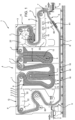
Figure 1 is a lateral view of a washing unit with a chain conveyor in accordance with the invention, with parts removed for clarity; -
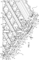
Figure 2 is a perspective view of the chain conveyor ofFigure 1 , with parts removed for clarity; and -
Figures 3 and 4 are transversal section taken along line III-III ofFigure 2 showing the chain conveyor ofFigures 1 and2 in the different wear conditions. - With reference to
figure 1 ,numeral 1 indicates a washing unit forwashing articles 2, in particular empty containers intended to be filled with a pourable product. -
Washing unit 1 substantially comprises: - a washing tunnel 3, in which
articles 2 are washed; - a
chain conveyor 4 for advancingarticles 2 inside washing tunnel 3 along a closed loop path P; and - a plurality of
treatment zones 5, which are arranged in washing tunnel 3 and comprise, in the embodiment shown,respective tanks 6 filled with respective cleaning agent and through whichchain conveyor 4advances articles 2. -
Washing unit 1 also comprises: - an infeed conveyor 8, which feeds a sequence of rows of
articles 2 to be cleaned to chainconveyor 4 at an input station I of washing tunnel 3; and - an
outfeed conveyor 14, which receives a sequence of rows of cleanedarticles 2 fromchain conveyor 4 at an output station O of washing tunnel 3. - Path P comprises a work branch Q and a return branch R.
- Work branch Q extends from input station I to output station O while return branch R extends from output station O to return station I.
- In the embodiment shown in
Figure 1 , path P lies on a vertical plane, andconveyors 8, 14advance articles 2 along a horizontal direction. - In particular,
treatment zones 5 comprise a prewash zone, a first cleaning zone, a second cleaning zone. - The prewash zone, the first cleaning zone, the second cleaning zone comprise
respective baths - For a better understanding, in
Figure 1 , the volume occupied by the cleaning solution has been highlighted by colouring the relative cross section in grey. - Due to the temperature of the cleaning agent,
articles 2 are heated up as they travel insidebath -
Treatment zones 5 also comprise arinsing zone 9, which is aimed to remove the chemical agents out ofarticles 2 and to cool them down.Rinsing zone 9 comprises a plurality ofsprinkling device 10 acting one after the other onarticles 2. -
Chain conveyor 4 advancesempty articles 2 along work branch Q and returns withoutarticles 2 along return branch R. - Bath 11, 12, 13 and rinsing
zone 9 are arranged, in this succession, along work branch Q of path P. - As evident from
Figure 1 , as they are advanced along work branch Q bychain conveyor 4,articles 2 can be arranged upside-down. - Furthermore,
chain conveyor 4 comprises, along work branch Q,: - a plurality of driven and
driving wheels 7, which mesh withconveyor chain 4 and causes the movement thereof along path P; and - a plurality of stationary supporting
structures 22, which interacts withconveyor chain 4 to prevent the bending thereof. - Return branch R of path P comprises, proceeding from station O to station I:
- a descending portion S;
- a substantially horizontal portion T; and
- an ascending portion U.
- With reference to
Figures 1 and2 ,chain conveyor 4 comprises: - a pair of chains 15 (only one of which is shown in
Figure 2 ) elongated parallel to path P and parallel to one another; and - a plurality of subsequent conveying
beams 16, which extend betweenchains 15 and orthogonally tochains 15 and path P. -
Chain conveyor 4 further comprises astationary guide 80 for supportingchains 15. -
Guide 80 is shaped in the same way as path P. - Each
beam 16 comprises a plurality ofseats 17 for holdingrelative articles 2. -
Seats 17 are aligned orthogonally to path P. Accordingly, alsoarticles 2, when conveyed along work branch Q, are aligned ontorelative beams 16 orthogonally to path P. - In particular, each
beam 16 comprises (Figure 2 ): - a
plate 18 onto which seats 17 are arranged and lying on a plane orthogonal to path P; - an
upstream crossbar 19, which protrudes orthogonally fromplate 18 andbounds seats 17 on the upstream side thereof, with reference to the advancing direction ofchain conveyor 4 along path P; - a
downstream crossbar 20, which protrudes orthogonally fromplate 18 on the opposite side ofcrossbar 19, and boundsseats 17 on the downstream side thereof, with reference to the advancing direction ofchain conveyor 4 along path P; and - a pair of
lateral crossbars 21, which protrude orthogonally fromplate 18, lie on respective planes orthogonal tocrossbars crossbars - In detail,
downstream crossbars seats 17. -
Crossbars 21 of eachbeam 16 are arranged one on the side of onechain 15 and the other on the side of theother chain 15. - Being
chains 15 identical to one another, only onechain 15 will be described in the following of the present description. -
Chain 15 substantially comprises (Figures 3 and 4 ): - a plurality of consecutive
hollow rollers 25 rolling ontoguide 80 about respective axes A orthogonal to path P; - a plurality of consecutive hollow bushes 26 (shown only in
Figures 3 and 4 ) onto whichrelative rollers 25 are rotatably mounted with respect to relative axes A; and - a plurality of
pins 27 onto whichbushes 26 are fitted, without possibility of relative rotational movement. - Each
roller 25 surrounds relative axle possibly formed by abush 26, which in turn surroundsrelative pins 27. Generally speaking, eachroller 25 is rotatably mounted on an axle, possibly in the shape of abush 26 surrounding apin 27. - Each assembly formed by a
roller 25, relative axle orbush 26 andrelative pin 27 extends about a common relative axis A. - Each
roller 25 comprises a relativeinner surface 30 with respect to relative axis A. - Each axle or
bush 26 comprises a relativeouter surface 31 with respect to relative axis A. -
Surface 30 of eachroller 25 rolls oversurface 31 of relative axle orbush 26. -
Surfaces - In particular, diameter di increases with the time due to the wear effect while diameter De of the axle or
bushing 26 decreases with the time due to the wear effect. - As evident from
Figures 3 , when wear effect are neglectable, diameter di equals value di1 while diameter De equals value De1. In this condition di1 substantially equals De1. - Due to the wear effect (
Figure 4 ), diameter di reaches value di2 higher than di1 while diameter De1 reaches value De2 smaller than De1. - In this way, a radial gap (magnified in
Figure 4 for the sake of clarity) betweensurfaces - As evident from
Figure 4 , each radial gap extends on the side ofsurface 31 of relative axle orbush 26 which is opposite to guide 80. - Each
roller 25 also comprises anouter surface 32 which is opposite toinner surface 30 and rolls ontoguide 80. - A
bush 26 also comprises aninner surface 33, which is opposite to surface 31 and is fitted ontorelative pin 27. An axle may form the merging of abush 26 andrelative pin 27. - Each axle or
bush 26 is connected to the immediately upstream (downstream) axle orbush 26 by means of a pair oflinks bush 26 with respect torelative roller 25. - Each
pin 27 is connected to the immediately downstream (upstream)pin 27 by means of a pair oflinks bush 26 with respect torelative roller 25. -
Links roller 25 andbush 26 shown inFigures 3 and 4 , axially interposed betweencorresponding links -
Links relative roller 25 with respect torelative beam 16. - In particular, links 37 are arranged on the opposite side of
relative links 35 with respect to correspondingroller 25. - Each
link -
Links respective surfaces -
Surface 45 of eachlink seats 17 ofrespective beam 16 whilesurface 46 is arranged on the opposite side ofseats 17 and on the side ofguide 80. -
Links conveyor chain 4. -
Links relative roller 25 with respect torelative beam 16. -
Links 36 is arranged on the opposite side ofrelative links 38 with respect to corresponding beams 16. - Each
link - a pair of
ends 50, 51 (Figure 2 ) fitted to respective consecutive bushes 26 (or pins 27, or axles) bound byrespective surfaces 47, 48 (Figures 3 and 4 ) arranged respectively on the side ofrelative beam 16 and the side ofguide 80; - a
main body 52, which is arranged betweenportions - a
portion 53 which laterally protrudes frombody 52 towardsrelative beam 16 and is screwed to alateral end 41 ofrelative beam 16 by means of a pair ofscrews 42. -
Body 52 andportion 53 of eachlink -
Links conveyor chain 4. - Lateral ends 41 of each
beam 16 are, in the embodiment shown, arranged on respective opposite sides ofcrossbars 21 with respect toseats 17. -
Surfaces structures 22, aschain conveyor 4 advances along work branch W of path P. - In the embodiment shown,
portions 53 are arranged on the opposite side ofrelative beams 16 with respect to correspondingseats 17. - Advantageously,
chain conveyor 4 comprise a pair ofsensors 60, which are configured to generating a signal, which is associated to the radial gap due to the wear betweeninner surface 30 of eachroller 25 andouter surface 31 of correspondingbush 26. - Furthermore,
chain conveyor 4 comprises a human machine interface 61 (only schematically shown inFigures 3 and 4 ) which is functionally connected tosensor 60 and is configured to generate a warning signal in case the radial wear exceeds a threshold value, without interrupting the operation ofchain conveyor 4. - Preferably, the warning signal is generated in advance with respect to a critical solution, in order to leave the operator the time to order a
new chain conveyor 4. The human machine interface shows the result of a calculation done by a control unit, possibly of thewashing unit 1 and connected to the at least onesensor 60, said calculation consisting in assessing the current wear status, possibly as described below, monitoring its evolution over time of production, and predicting a future breakage, before which a maintenance operation must be taken. -
Chain conveyor 4 comprises, in the embodiment show, asensor 60 for onechain 5 and anothersensor 60 for theother chain 5. - With reference to
Figures 3 and 4 ,sensor 60 generates a signal corresponding to a distance H between afixed point 62 ofsensor 60 andsurface 45 oflinks 35. - Distance H is measured orthogonally to path P and axes A.
- As evident from
Figure 3 and 4 , distance H depends on the radial gap due to wear betweensurfaces - Still more precisely, distance H increases while wear between
surfaces - As matter of fact, distance H equals value L when diameter De1 of
inner surface 31 ofrollers 25 equals diameter di1 ofouter surface 30 of correspondingbushes 26, i.e. when the wear betweenrollers 25 and relative axles orbushes 26 is neglectable (Figure 3 ). - When, due to the operation of
chain conveyor 4, diameter De2 ofinner surface 31 is smaller than diameter De1 and diameter di2 ofouter surface 30 is greater than diameter di1, distance H detected bysensor 51 equals:
- In greater detail,
sensor 60 is arranged along descending portion S of return branch R. -
Chain conveyor 4 comprises a supporting element 81 (Figures 1 and2 ), which is arranged on the opposite side ofchain conveyor 4 with respect tosensor 60. - In the embodiment shown,
sensor 60 is an optical sensor, preferably a laser sensor. - Preferably,
sensor 60 operates according to a triangulation technique, i.e. evaluates distance H on the basis of: - the distance detected between two points on
surface 45 on eachlinks 37 and the fixedpoint 62 ofsensor 51; and - the angle between the segments connecting the two points on each
link 37 and the fixedpoint 62 on surface andsensor 51. - Alternatively,
sensor 60 could be an inductive or a magnetic sensor. - The operation of
chain conveyor 4 is described with reference to only onebeam 16. -
Beam 16 cyclically travels along path P inside washing unit - In particular,
beam 16 is fed witharticles 2 to be cleaned at input station I by infeed conveyor 8, advancesarticles 2 inside washing tunnel 3 along work branch Q, discharges cleaned articles at output station O ontooutfeed conveyor 14 and returns along return branch R withoutarticles 2. - In particular, as
chain conveyor 4 advances,rollers 25 of eachchain 15 roll overguide 80. In the meanwhile,rollers 25 roll over relative axles orbushes 26 about relative axes A. - The wear effect due to the relative rolling movement of
innersurfaces 30 ofrollers 25 with respect torespective outersurfaces 31 of corresponding axles orbushes 26 causes an increase in diameter di ofinnersurfaces 30 ofrollers 25 and a decrease in diameter De ofouter surfaces 31 of bushes 26 (seeFigures 3 and 4 ). Thus, a radial gap betweensurfaces - As they are advanced along work portion Q,
articles 2 pass throughbath devices 10 of rinsingzone 6. - As they are advanced along descending portion S of return branch R,
sensor 60 detects distance H between afixed point 62 ofsensor 60 andsurface 45 oflinks 35 ofchains 15. - It is therefore possible to constantly monitor the residual lifetime of
chain conveyor 4. A possible calculation therefor has been described earlier. - In case distance H is greater than a threshold value,
human machine interface 61 generates a warning signal, without interrupting the operation ofchain conveyor 4. - Preferably, the warning signal is generated in advance with respect to a critical solution, in order to leave enough time to order and deliver a
new chain conveyor 4. - From an analysis of the features of
chain conveyor 4 and of the method according to the present invention, the advantages it allows to obtain are apparent. - In particular,
sensor 60 is configured to generate a signal which is associated to the radial gap generated by the wear effect betweeninner surfaces 30 ofrollers 25 andouter surfaces 31. - In this way, when the radial gap exceeds a threshold value, a warning signal is generated, well before breakage occurs, without interrupting the operation of
chain conveyor 4. - In particular, the warning signal can be generated when the lifetime of
chain conveyor 4 is still long enough to wait for order and the delivery of anew chain conveyor 4. - It is therefore possible to constantly monitor the residual lifetime of
chain conveyor 4, without interrupting the operation thereof. - As a result, the amount of time along which the operation of
washing unit 1 is interrupted is dramatically reduced, with a strong benefit in the throughput ofwashing unit 1 and of downstream filling and labelling unit. - Furthermore,
sensor 60 detects distance H between fixedpoint 62 and surfaces 45 oflinks 35, which are connected torelative bushes 26. Due to the fact thatlinks 35 substantially do not undergo wear effects, the measure of radial gap is particularly reliable. - In addition, surfaces 45 of
links 35 slide ontostructures 22, as they travel along path Q and, are, therefore, particularly cleaned. - Accordingly, it is dramatically reduced the risk that some dirty substance could remain onto
surfaces 45 and penalize the reliability of the measure carried out bysensor 60. -
Sensor 60 is arranged at portion S of return path R, i.e. in a position without water, temperature variation and chemicals agents. Thus, the measure ofsensor 60 is particularly reliable. - Finally,
sensor 60 can be easily applied onto existingwashing unit 1, without substantially modification of the latter. - Clearly, changes may be made to the
chain conveyor 4 and method as described and illustrated herein without, however, departing from the scope of protection as defined in the accompanying claims.
Claims (11)
- A chain conveyor (4) for conveying a plurality of empty articles (2) along a path (P), comprising:- a plurality of rollers (25) adapted to roll onto a guide (80) and about an axis (A);- a plurality of axles about which said respective rollers (25) are rotatably mounted, like bushes (26);- a plurality of first and second links (35; 36, 38) for connecting respective pairs of subsequent axles or bushes (26); and- a plurality of conveying beams (16) for said articles (2), which are supported at least indirectly by said relative axles or bushes (26);
each said roller (25) comprising a radially inner surface (30) which rotates, in use, onto a radially outer surface (31) of said respective axle or bush (26); andcomprising a sensor (60), which is configured for generating a signal, which is associated to the radial gap due to the wear between said inner surface (30) of said roller (25) and said outer surface (31)of said bush (26),characterized in that the sensor (60) senses the distance (H) between said sensor (60) and reference surface (45) directly or indirectly connected to relative said axles or bushes (26)such that said signal generated by said sensor (60) is associated to the distance (H) between said sensor (60) and reference surfaces (45) directly or indirectly connected to relative said axles or bushes (26); said reference surfaces (45) being carried by said first links (35) and being radially opposite to said relative axles or bushes (26), andsaid distance (H) being measured orthogonally to said path (P) and said axes (A). - The chain conveyor of claim 1, characterized in that said first links (35) are arranged on one axial side of respective pair of subsequent axles or bushes (26); said axial side being opposite to said relative conveying beam (16) with respect to said relative roller (25);
said second links (36, 38) being fixed to said relative conveying beams (16). - The chain conveyor of any one of the foregoing claims, characterized by comprising a human machine interface (61), which is functionally connected to said sensor (60) and is configured to display a warning message in case said radial gap exceeds a threshold value.
- The chain conveyor of any one of the foregoing claims, characterized in that said path (P) comprises:- an input station (I), at which said chain conveyor (4) is, in use, fed with said articles (2) to be conveyed;- an output station (O), at which said chain conveyor (4) outputs, in use, said conveyed articles (2);- a work branch (Q), which extends from said input station (I) to said output station (O); and- a return branch (R), which extends from said output station (I) to said input station (O);said sensor (60) being fixed with respect to said path (P) and being located at said return branch (R).
- The chain conveyor of claim 4, characterized in that said return branch (R) comprises a portion (S), which extends as of said output station (O) and is, in use, descending;
said sensor (60) being located in front of said portion (S). - The chain conveyor of any one of the previous claims, characterized in that said sensor (60) is an optical sensor, a magnetic sensor or an inductive sensor.
- The chain conveyor of claim 6, characterized in that said sensor is an optical laser sensor.
- A washing unit (1) for treating empty articles (2), comprising:- at least one treatment station (5) with a bath (11, 12, 13) fillable with a liquid treatment agent;- a rinsing station (6) for rinsing said washed articles (2);- a chain conveyor (4) according to any one of the foregoing claims, and- a guide (80) onto which the rollers (25) of said chain conveyor (4) roll; andsaid chain conveyor (4) being adapted to advance said articles (2) to be cleaned, in use, across said bath (11, 12, 13).
- The unit of claim 8, characterized by comprising :- a wheel (7) cooperating with said conveyor chain (4); and- a fixed structure (22), which is arranged immediately downstream of said wheel (7), according to the advancing direction of said articles (2) along said path (P) and is adapted to support said conveyor chain (4);said fixed structure (22) cooperating with said reference surface (45) of said first link (35), as said chain conveyor (4) advances, in use, along said path (P).
- A method for detecting the wear condition of a chain conveyor (4) according to claim 1 for conveying a plurality of articles (2) along a path (P);said method comprising the step i) of sensing the radial gap due to wear between said inner surface (30) and said outer surface (31),wherein said step i) comprises the step ii) of sensing the distance (H) between said sensor (60) and reference surfaces (45) which are directly or indirectly connected to said axles or bushes (26), wherein said step ii) comprises the step iii) of sensing distance (H) between said sensor (60) and reference surface (45) of said first links (35), which are radially opposite to said axle or bushes (26).
- The method of claim 10, comprising the steps of:iv) feeding said articles (2) to said chain conveyor (4) at an input station (I) of said path (P) ;v) advancing said chain conveyor (4) along a work branch (Q) from said input station (I) to an output station (O);vi) discharging said articles (2) at said output station (O);vii) advancing said chain conveyor (4) along a return branch (R) from said output station (O) to said input station (I);said step i) comprising the step viii) of sensing said radial gap during said step vii).
Priority Applications (4)
| Application Number | Priority Date | Filing Date | Title |
|---|---|---|---|
| EP16207385.2A EP3342734B8 (en) | 2016-12-29 | 2016-12-29 | Chain conveyor for conveying a plurality of articles and method for detecting the wear condition of the chain conveyor |
| ARP170103683A AR110589A1 (en) | 2016-12-29 | 2017-12-26 | CHAIN CONVEYOR TAPE TO TRANSPORT A PLURALITY OF ITEMS AND METHOD OF DETECTION OF THE STATE OF WEAR OF THE SAME |
| PCT/EP2017/084664 WO2018122271A1 (en) | 2016-12-29 | 2017-12-27 | Chain conveyor for conveying a plurality of articles and method for detecting the wear condition of the chain conveyor |
| CN201780081122.XA CN110114287B (en) | 2016-12-29 | 2017-12-27 | Chain conveyor for conveying multiple items and method for detecting wear condition of chain conveyor |
Applications Claiming Priority (1)
| Application Number | Priority Date | Filing Date | Title |
|---|---|---|---|
| EP16207385.2A EP3342734B8 (en) | 2016-12-29 | 2016-12-29 | Chain conveyor for conveying a plurality of articles and method for detecting the wear condition of the chain conveyor |
Publications (3)
| Publication Number | Publication Date |
|---|---|
| EP3342734A1 EP3342734A1 (en) | 2018-07-04 |
| EP3342734B1 true EP3342734B1 (en) | 2023-02-15 |
| EP3342734B8 EP3342734B8 (en) | 2023-03-22 |
Family
ID=57629478
Family Applications (1)
| Application Number | Title | Priority Date | Filing Date |
|---|---|---|---|
| EP16207385.2A Active EP3342734B8 (en) | 2016-12-29 | 2016-12-29 | Chain conveyor for conveying a plurality of articles and method for detecting the wear condition of the chain conveyor |
Country Status (4)
| Country | Link |
|---|---|
| EP (1) | EP3342734B8 (en) |
| CN (1) | CN110114287B (en) |
| AR (1) | AR110589A1 (en) |
| WO (1) | WO2018122271A1 (en) |
Families Citing this family (2)
| Publication number | Priority date | Publication date | Assignee | Title |
|---|---|---|---|---|
| EP3772383B1 (en) * | 2019-08-06 | 2023-07-19 | Sidel S.P.A. | Beam for a washing machine and method for connecting a wall of a beam to a connecting assembly of the beam |
| DE102020133719A1 (en) * | 2020-12-16 | 2022-06-23 | Homag Gmbh | conveyor |
Family Cites Families (8)
| Publication number | Priority date | Publication date | Assignee | Title |
|---|---|---|---|---|
| US2444925A (en) * | 1940-07-25 | 1948-07-13 | Charles E Kimball | Container washing machine |
| US2984334A (en) * | 1957-12-16 | 1961-05-16 | Barry Wehmiller Machinery Co | Bottle carrier |
| US5409545A (en) * | 1993-03-04 | 1995-04-25 | Environmental Sampling Supply, Inc. | Apparatus and method for cleaning containers |
| JPH10300426A (en) * | 1997-05-01 | 1998-11-13 | Tsubakimoto Chain Co | Roller chain wear detecting method and device |
| JP2010501446A (en) * | 2006-08-24 | 2010-01-21 | フロスト・リンクス・インコーポレイテッド | Chain wear monitoring device |
| DE102011003198A1 (en) * | 2011-01-26 | 2012-08-09 | Krones Aktiengesellschaft | drive chain |
| EP2727760B1 (en) | 2012-10-31 | 2016-05-25 | Yamaha Hatsudoki Kabushiki Kaisha | Driving apparatus for use in electric vehicle and electric vehicle |
| EP2727660B1 (en) * | 2012-11-05 | 2015-08-26 | Gebo Packaging Solutions Italy SRL | A unit for treating containers and a method for the reconfiguration of a unit for treating containers |
-
2016
- 2016-12-29 EP EP16207385.2A patent/EP3342734B8/en active Active
-
2017
- 2017-12-26 AR ARP170103683A patent/AR110589A1/en active IP Right Grant
- 2017-12-27 WO PCT/EP2017/084664 patent/WO2018122271A1/en not_active Ceased
- 2017-12-27 CN CN201780081122.XA patent/CN110114287B/en active Active
Also Published As
| Publication number | Publication date |
|---|---|
| WO2018122271A1 (en) | 2018-07-05 |
| CN110114287B (en) | 2021-08-24 |
| EP3342734B8 (en) | 2023-03-22 |
| AR110589A1 (en) | 2019-04-10 |
| CN110114287A (en) | 2019-08-09 |
| EP3342734A1 (en) | 2018-07-04 |
Similar Documents
| Publication | Publication Date | Title |
|---|---|---|
| EP3401028B1 (en) | A washing unit for treating empty articles | |
| DE102007022235B4 (en) | Batch transport of rod-shaped articles of the tobacco processing industry | |
| EP3401027B1 (en) | A feeding system and method for feeding a washing unit with empty articles | |
| EP3342734A1 (en) | Chain conveyor for conveying a plurality of articles and method for detecting the wear condition of the chain conveyor | |
| WO2015036197A1 (en) | Device and method for transporting containers in a container treatment system | |
| EP3003879B1 (en) | Method and machine for treating containers | |
| JP2010507544A (en) | Bottle distribution table for entrance to single channel | |
| ITTO940597A1 (en) | DEVICE AND PROCEDURE FOR REGULATING THE ADVANCE OF ITEMS, FOR EXAMPLE IN PLANTS FOR THE AUTOMATIC PACKAGING OF FOOD PRODUCTS. | |
| WO2007006452A1 (en) | Container treatment machine | |
| CN102616528B (en) | Drive train and container cleaning machine comprising the drive train | |
| NL1009569C2 (en) | Endless conveyor. | |
| EP2845940B1 (en) | Apparatus and method for the washing of fabrics | |
| KR101700635B1 (en) | Belt conveyor for loading and unloading of material | |
| NL8120035A (en) | Apparatus for handling bottles upside down and the like. | |
| WO2007000441A1 (en) | Method and system for conveying and selecting fruit and vegetable products | |
| WO2003068422A1 (en) | Device and method for washing container-gripping elements | |
| CN116897132A (en) | Conveyor belts for transporting materials and packaging systems including such conveyor belts | |
| EP3656479B1 (en) | Washing machine and relative method for washing empty containers | |
| EP2777830B1 (en) | Method ans apparatus for cleaning a transport segment | |
| EP3546079B1 (en) | An end portion for a pocket for receiving empty articles to be washed and advanced along a washing treatment path | |
| EP3572360A1 (en) | A processing unit for washing empty articles and related method | |
| NL193445C (en) | Bottle cleaning machine. | |
| EP3836805B1 (en) | Method and apparatus for conversion of moving stream of oppositely oriented rod-like articles | |
| WO2019185648A1 (en) | A washing unit for washing empty articles and related method | |
| EP4671163A1 (en) | DEVICE FOR CONVEYING CONTAINERS AND ASSOCIATED OPERATING PROCEDURE |
Legal Events
| Date | Code | Title | Description |
|---|---|---|---|
| PUAI | Public reference made under article 153(3) epc to a published international application that has entered the european phase |
Free format text: ORIGINAL CODE: 0009012 |
|
| STAA | Information on the status of an ep patent application or granted ep patent |
Free format text: STATUS: THE APPLICATION HAS BEEN PUBLISHED |
|
| AK | Designated contracting states |
Kind code of ref document: A1 Designated state(s): AL AT BE BG CH CY CZ DE DK EE ES FI FR GB GR HR HU IE IS IT LI LT LU LV MC MK MT NL NO PL PT RO RS SE SI SK SM TR |
|
| AX | Request for extension of the european patent |
Extension state: BA ME |
|
| STAA | Information on the status of an ep patent application or granted ep patent |
Free format text: STATUS: REQUEST FOR EXAMINATION WAS MADE |
|
| 17P | Request for examination filed |
Effective date: 20190104 |
|
| RBV | Designated contracting states (corrected) |
Designated state(s): AL AT BE BG CH CY CZ DE DK EE ES FI FR GB GR HR HU IE IS IT LI LT LU LV MC MK MT NL NO PL PT RO RS SE SI SK SM TR |
|
| STAA | Information on the status of an ep patent application or granted ep patent |
Free format text: STATUS: EXAMINATION IS IN PROGRESS |
|
| 17Q | First examination report despatched |
Effective date: 20210607 |
|
| RAP3 | Party data changed (applicant data changed or rights of an application transferred) |
Owner name: SIDEL END OF LINE & TUNNELS SOLUTIONS SRL |
|
| GRAP | Despatch of communication of intention to grant a patent |
Free format text: ORIGINAL CODE: EPIDOSNIGR1 |
|
| STAA | Information on the status of an ep patent application or granted ep patent |
Free format text: STATUS: GRANT OF PATENT IS INTENDED |
|
| INTG | Intention to grant announced |
Effective date: 20220906 |
|
| GRAS | Grant fee paid |
Free format text: ORIGINAL CODE: EPIDOSNIGR3 |
|
| GRAA | (expected) grant |
Free format text: ORIGINAL CODE: 0009210 |
|
| STAA | Information on the status of an ep patent application or granted ep patent |
Free format text: STATUS: THE PATENT HAS BEEN GRANTED |
|
| REG | Reference to a national code |
Ref country code: DE Ref legal event code: R081 Ref document number: 602016077815 Country of ref document: DE Owner name: SIDEL S.P.A., IT Free format text: FORMER OWNER: SIDEL END OF LINE & TUNNELS SOLUTIONS SRL, PARMA, IT |
|
| AK | Designated contracting states |
Kind code of ref document: B1 Designated state(s): AL AT BE BG CH CY CZ DE DK EE ES FI FR GB GR HR HU IE IS IT LI LT LU LV MC MK MT NL NO PL PT RO RS SE SI SK SM TR |
|
| REG | Reference to a national code |
Ref country code: CH Ref legal event code: EP Ref country code: GB Ref legal event code: FG4D |
|
| RAP2 | Party data changed (patent owner data changed or rights of a patent transferred) |
Owner name: SIDEL S.P.A. |
|
| REG | Reference to a national code |
Ref country code: DE Ref legal event code: R096 Ref document number: 602016077815 Country of ref document: DE |
|
| REG | Reference to a national code |
Ref country code: CH Ref legal event code: PK Free format text: BERICHTIGUNG B8 Ref country code: AT Ref legal event code: REF Ref document number: 1548144 Country of ref document: AT Kind code of ref document: T Effective date: 20230315 Ref country code: IE Ref legal event code: FG4D |
|
| REG | Reference to a national code |
Ref country code: LT Ref legal event code: MG9D |
|
| REG | Reference to a national code |
Ref country code: NL Ref legal event code: MP Effective date: 20230215 |
|
| P01 | Opt-out of the competence of the unified patent court (upc) registered |
Effective date: 20230523 |
|
| REG | Reference to a national code |
Ref country code: AT Ref legal event code: MK05 Ref document number: 1548144 Country of ref document: AT Kind code of ref document: T Effective date: 20230215 |
|
| PG25 | Lapsed in a contracting state [announced via postgrant information from national office to epo] |
Ref country code: RS Free format text: LAPSE BECAUSE OF FAILURE TO SUBMIT A TRANSLATION OF THE DESCRIPTION OR TO PAY THE FEE WITHIN THE PRESCRIBED TIME-LIMIT Effective date: 20230215 Ref country code: PT Free format text: LAPSE BECAUSE OF FAILURE TO SUBMIT A TRANSLATION OF THE DESCRIPTION OR TO PAY THE FEE WITHIN THE PRESCRIBED TIME-LIMIT Effective date: 20230615 Ref country code: NO Free format text: LAPSE BECAUSE OF FAILURE TO SUBMIT A TRANSLATION OF THE DESCRIPTION OR TO PAY THE FEE WITHIN THE PRESCRIBED TIME-LIMIT Effective date: 20230515 Ref country code: NL Free format text: LAPSE BECAUSE OF FAILURE TO SUBMIT A TRANSLATION OF THE DESCRIPTION OR TO PAY THE FEE WITHIN THE PRESCRIBED TIME-LIMIT Effective date: 20230215 Ref country code: LV Free format text: LAPSE BECAUSE OF FAILURE TO SUBMIT A TRANSLATION OF THE DESCRIPTION OR TO PAY THE FEE WITHIN THE PRESCRIBED TIME-LIMIT Effective date: 20230215 Ref country code: LT Free format text: LAPSE BECAUSE OF FAILURE TO SUBMIT A TRANSLATION OF THE DESCRIPTION OR TO PAY THE FEE WITHIN THE PRESCRIBED TIME-LIMIT Effective date: 20230215 Ref country code: HR Free format text: LAPSE BECAUSE OF FAILURE TO SUBMIT A TRANSLATION OF THE DESCRIPTION OR TO PAY THE FEE WITHIN THE PRESCRIBED TIME-LIMIT Effective date: 20230215 Ref country code: ES Free format text: LAPSE BECAUSE OF FAILURE TO SUBMIT A TRANSLATION OF THE DESCRIPTION OR TO PAY THE FEE WITHIN THE PRESCRIBED TIME-LIMIT Effective date: 20230215 Ref country code: AT Free format text: LAPSE BECAUSE OF FAILURE TO SUBMIT A TRANSLATION OF THE DESCRIPTION OR TO PAY THE FEE WITHIN THE PRESCRIBED TIME-LIMIT Effective date: 20230215 |
|
| PG25 | Lapsed in a contracting state [announced via postgrant information from national office to epo] |
Ref country code: SE Free format text: LAPSE BECAUSE OF FAILURE TO SUBMIT A TRANSLATION OF THE DESCRIPTION OR TO PAY THE FEE WITHIN THE PRESCRIBED TIME-LIMIT Effective date: 20230215 Ref country code: PL Free format text: LAPSE BECAUSE OF FAILURE TO SUBMIT A TRANSLATION OF THE DESCRIPTION OR TO PAY THE FEE WITHIN THE PRESCRIBED TIME-LIMIT Effective date: 20230215 Ref country code: IS Free format text: LAPSE BECAUSE OF FAILURE TO SUBMIT A TRANSLATION OF THE DESCRIPTION OR TO PAY THE FEE WITHIN THE PRESCRIBED TIME-LIMIT Effective date: 20230615 Ref country code: GR Free format text: LAPSE BECAUSE OF FAILURE TO SUBMIT A TRANSLATION OF THE DESCRIPTION OR TO PAY THE FEE WITHIN THE PRESCRIBED TIME-LIMIT Effective date: 20230516 Ref country code: FI Free format text: LAPSE BECAUSE OF FAILURE TO SUBMIT A TRANSLATION OF THE DESCRIPTION OR TO PAY THE FEE WITHIN THE PRESCRIBED TIME-LIMIT Effective date: 20230215 |
|
| PG25 | Lapsed in a contracting state [announced via postgrant information from national office to epo] |
Ref country code: SM Free format text: LAPSE BECAUSE OF FAILURE TO SUBMIT A TRANSLATION OF THE DESCRIPTION OR TO PAY THE FEE WITHIN THE PRESCRIBED TIME-LIMIT Effective date: 20230215 Ref country code: RO Free format text: LAPSE BECAUSE OF FAILURE TO SUBMIT A TRANSLATION OF THE DESCRIPTION OR TO PAY THE FEE WITHIN THE PRESCRIBED TIME-LIMIT Effective date: 20230215 Ref country code: EE Free format text: LAPSE BECAUSE OF FAILURE TO SUBMIT A TRANSLATION OF THE DESCRIPTION OR TO PAY THE FEE WITHIN THE PRESCRIBED TIME-LIMIT Effective date: 20230215 Ref country code: DK Free format text: LAPSE BECAUSE OF FAILURE TO SUBMIT A TRANSLATION OF THE DESCRIPTION OR TO PAY THE FEE WITHIN THE PRESCRIBED TIME-LIMIT Effective date: 20230215 Ref country code: CZ Free format text: LAPSE BECAUSE OF FAILURE TO SUBMIT A TRANSLATION OF THE DESCRIPTION OR TO PAY THE FEE WITHIN THE PRESCRIBED TIME-LIMIT Effective date: 20230215 |
|
| REG | Reference to a national code |
Ref country code: DE Ref legal event code: R097 Ref document number: 602016077815 Country of ref document: DE |
|
| PG25 | Lapsed in a contracting state [announced via postgrant information from national office to epo] |
Ref country code: SK Free format text: LAPSE BECAUSE OF FAILURE TO SUBMIT A TRANSLATION OF THE DESCRIPTION OR TO PAY THE FEE WITHIN THE PRESCRIBED TIME-LIMIT Effective date: 20230215 |
|
| PLBE | No opposition filed within time limit |
Free format text: ORIGINAL CODE: 0009261 |
|
| STAA | Information on the status of an ep patent application or granted ep patent |
Free format text: STATUS: NO OPPOSITION FILED WITHIN TIME LIMIT |
|
| 26N | No opposition filed |
Effective date: 20231116 |
|
| PG25 | Lapsed in a contracting state [announced via postgrant information from national office to epo] |
Ref country code: SI Free format text: LAPSE BECAUSE OF FAILURE TO SUBMIT A TRANSLATION OF THE DESCRIPTION OR TO PAY THE FEE WITHIN THE PRESCRIBED TIME-LIMIT Effective date: 20230215 |
|
| REG | Reference to a national code |
Ref country code: CH Ref legal event code: PL |
|
| PG25 | Lapsed in a contracting state [announced via postgrant information from national office to epo] |
Ref country code: LU Free format text: LAPSE BECAUSE OF NON-PAYMENT OF DUE FEES Effective date: 20231229 |
|
| PG25 | Lapsed in a contracting state [announced via postgrant information from national office to epo] |
Ref country code: MC Free format text: LAPSE BECAUSE OF FAILURE TO SUBMIT A TRANSLATION OF THE DESCRIPTION OR TO PAY THE FEE WITHIN THE PRESCRIBED TIME-LIMIT Effective date: 20230215 |
|
| GBPC | Gb: european patent ceased through non-payment of renewal fee |
Effective date: 20231229 |
|
| REG | Reference to a national code |
Ref country code: BE Ref legal event code: MM Effective date: 20231231 |
|
| PG25 | Lapsed in a contracting state [announced via postgrant information from national office to epo] |
Ref country code: MC Free format text: LAPSE BECAUSE OF FAILURE TO SUBMIT A TRANSLATION OF THE DESCRIPTION OR TO PAY THE FEE WITHIN THE PRESCRIBED TIME-LIMIT Effective date: 20230215 Ref country code: LU Free format text: LAPSE BECAUSE OF NON-PAYMENT OF DUE FEES Effective date: 20231229 |
|
| REG | Reference to a national code |
Ref country code: IE Ref legal event code: MM4A |
|
| PG25 | Lapsed in a contracting state [announced via postgrant information from national office to epo] |
Ref country code: IE Free format text: LAPSE BECAUSE OF NON-PAYMENT OF DUE FEES Effective date: 20231229 |
|
| PG25 | Lapsed in a contracting state [announced via postgrant information from national office to epo] |
Ref country code: GB Free format text: LAPSE BECAUSE OF NON-PAYMENT OF DUE FEES Effective date: 20231229 |
|
| PG25 | Lapsed in a contracting state [announced via postgrant information from national office to epo] |
Ref country code: BE Free format text: LAPSE BECAUSE OF NON-PAYMENT OF DUE FEES Effective date: 20231231 |
|
| PG25 | Lapsed in a contracting state [announced via postgrant information from national office to epo] |
Ref country code: CH Free format text: LAPSE BECAUSE OF NON-PAYMENT OF DUE FEES Effective date: 20231231 |
|
| PG25 | Lapsed in a contracting state [announced via postgrant information from national office to epo] |
Ref country code: IE Free format text: LAPSE BECAUSE OF NON-PAYMENT OF DUE FEES Effective date: 20231229 Ref country code: GB Free format text: LAPSE BECAUSE OF NON-PAYMENT OF DUE FEES Effective date: 20231229 Ref country code: CH Free format text: LAPSE BECAUSE OF NON-PAYMENT OF DUE FEES Effective date: 20231231 Ref country code: BE Free format text: LAPSE BECAUSE OF NON-PAYMENT OF DUE FEES Effective date: 20231231 |
|
| PG25 | Lapsed in a contracting state [announced via postgrant information from national office to epo] |
Ref country code: BG Free format text: LAPSE BECAUSE OF FAILURE TO SUBMIT A TRANSLATION OF THE DESCRIPTION OR TO PAY THE FEE WITHIN THE PRESCRIBED TIME-LIMIT Effective date: 20230215 |
|
| PG25 | Lapsed in a contracting state [announced via postgrant information from national office to epo] |
Ref country code: BG Free format text: LAPSE BECAUSE OF FAILURE TO SUBMIT A TRANSLATION OF THE DESCRIPTION OR TO PAY THE FEE WITHIN THE PRESCRIBED TIME-LIMIT Effective date: 20230215 |
|
| PG25 | Lapsed in a contracting state [announced via postgrant information from national office to epo] |
Ref country code: CY Free format text: LAPSE BECAUSE OF FAILURE TO SUBMIT A TRANSLATION OF THE DESCRIPTION OR TO PAY THE FEE WITHIN THE PRESCRIBED TIME-LIMIT; INVALID AB INITIO Effective date: 20161229 |
|
| PG25 | Lapsed in a contracting state [announced via postgrant information from national office to epo] |
Ref country code: HU Free format text: LAPSE BECAUSE OF FAILURE TO SUBMIT A TRANSLATION OF THE DESCRIPTION OR TO PAY THE FEE WITHIN THE PRESCRIBED TIME-LIMIT; INVALID AB INITIO Effective date: 20161229 |
|
| PG25 | Lapsed in a contracting state [announced via postgrant information from national office to epo] |
Ref country code: TR Free format text: LAPSE BECAUSE OF FAILURE TO SUBMIT A TRANSLATION OF THE DESCRIPTION OR TO PAY THE FEE WITHIN THE PRESCRIBED TIME-LIMIT Effective date: 20230215 |
|
| PGFP | Annual fee paid to national office [announced via postgrant information from national office to epo] |
Ref country code: DE Payment date: 20251126 Year of fee payment: 10 |
|
| PGFP | Annual fee paid to national office [announced via postgrant information from national office to epo] |
Ref country code: IT Payment date: 20251119 Year of fee payment: 10 |
|
| PGFP | Annual fee paid to national office [announced via postgrant information from national office to epo] |
Ref country code: FR Payment date: 20251119 Year of fee payment: 10 |