EP3342700A1 - Rear pressure bulkhead - Google Patents
Rear pressure bulkhead Download PDFInfo
- Publication number
- EP3342700A1 EP3342700A1 EP16382656.3A EP16382656A EP3342700A1 EP 3342700 A1 EP3342700 A1 EP 3342700A1 EP 16382656 A EP16382656 A EP 16382656A EP 3342700 A1 EP3342700 A1 EP 3342700A1
- Authority
- EP
- European Patent Office
- Prior art keywords
- rear pressure
- pressure bulkhead
- flat rear
- aircraft
- membrane
- Prior art date
- Legal status (The legal status is an assumption and is not a legal conclusion. Google has not performed a legal analysis and makes no representation as to the accuracy of the status listed.)
- Granted
Links
Images



Classifications
-
- B—PERFORMING OPERATIONS; TRANSPORTING
- B64—AIRCRAFT; AVIATION; COSMONAUTICS
- B64C—AEROPLANES; HELICOPTERS
- B64C1/00—Fuselages; Constructional features common to fuselages, wings, stabilising surfaces or the like
- B64C1/06—Frames; Stringers; Longerons ; Fuselage sections
- B64C1/10—Bulkheads
Definitions
- the invention relates to the field of rear pressure bulkheads in aircrafts and especially in airplanes.
- An aircraft rear pressure bulkhead is an airtight wall separating the cabin of the aircraft from the tail of the aircraft.
- An aircraft rear pressure bulkhead aims at sealing the rear part of the aircraft in order to maintain the cabin pressure in the aircraft.
- a curved rear pressure bulkhead at the rear of an airplane is robust with a good resistance to air pressure coming from cabin inside and presents a reduced global weight.
- the small angle made by the external periphery of the curved rear pressure bulkhead with the mean surface of the airplane fuselage to which it is attached leads to a better stress distribution on the whole of the curved rear pressure bulkhead and as well a better load transfer to the skin of the fuselage.
- this curved rear pressure bulkhead takes a substantial volume to be implemented at the rear of the airplane.
- FIG. 1 Such a first prior art is for example represented on figures 1 and 2 .
- figure 1 there is an airplane 1 comprising a cabin 2 and a tail 5 separated from each other by a curved rear pressure bulkhead 4 presenting resistance to air pressure 3 coming from the inside of cabin 2.
- the curved rear pressure bulkhead 4 is attached by attachments 8 to the fuselage wall 7, making an angle which is quite small, thereby better load distributing from on the whole surface of the curved rear pressure bulkhead 4 to the skin of the fuselage.
- a flat rear pressure bulkhead at the rear of an airplane comprises thick horizontal and vertical reinforcement beams crossed with one another.
- these thick horizontal and vertical reinforcement beams present two drawbacks.
- these thick reinforcement bars increase notably the global weight of this flat rear pressure bulkhead.
- these thick reinforcement bars notably increase the thickness of this rear pressure bulkhead, thereby taking a non-negligible volume to be implemented at the rear of the airplane.
- air pressure distribution into the flat rear pressure bulkhead implies a worst stress distribution in it.
- FIG. 3 Such a second prior art is for example represented on figure 3 .
- FIG 3 there is a flat panel 6 supported by thick horizontal and vertical reinforcements beams 9, crossing with one another, making a waffle bulkhead pattern of the flat panel 6 presenting about a dozen of squares 10.
- the thick reinforcement beams 9 present the drawbacks to increase simultaneously the weight, the thickness and the volume of this global flat rear pressure bulkhead 4.
- the object of the present invention is to alleviate at least partly the above mentioned drawbacks.
- the invention aims at providing for a rear pressure bulkhead which will go towards a first compromise which simultaneously allows for gaining some place as compared to a classical curved rear pressure bulkhead according to first prior art while keeping a comparable resistance to cabin air pressure as this classical curved rear pressure bulkhead, and towards a second compromise which allows for keeping a comparable resistance to cabin air pressure as the flat rear pressure bulkhead according to second prior art while presenting reduced weight and volume as compared to this flat rear pressure bulkhead.
- the invention proposes a rear pressure bulkhead which will present an improved global compromise between its robustness, i.e. resistance to cabin air pressure, its weight and its filled volume, i.e. especially its thickness corresponding to volume in the longitudinal direction of the aircraft or the airplane.
- the invention proposes on the one hand to make a flat rear pressure bulkhead in order to give more space to passengers in cabin and for example to gain thereby at least one passenger row of seats in the cabin in case of an airplane, while on the other hand keeping a good compromise between its robustness and its weight and its thickness, by modifying its structure to make it rather robust, light and compact.
- an aircraft flat rear pressure bulkhead having a layered stacking including: an airtight membrane, a honeycombed reinforcement grid, an interface in between distributing grid strain over membrane surface.
- an aircraft flat rear pressure bulkhead including: a honeycombed reinforcement grid, airtight membranes respectively filling honeycombs of said honeycombed reinforcement grid, said honeycombs preferably being polygonal honeycombs with at least six sides, and more preferably being hexagonal honeycombs.
- Preferred embodiments comprise one or more of the following features, which can be taken separately or together, either in partial combination or in full combination, associated to one or the other of previous objects of the invention.
- said honeycombed reinforcement grid comprises at least 40 honeycombs, preferably at least 50 honeycombs.
- the number of noneycombs may also depend on the size of the aircraft and the difference the pressure between the atmosphere and the cabin.
- increasing the number of the reinforcements cells in the lattice of the grid increases grid resistance to air pressure.
- making numerous reinforcements cells in the lattice of the grid allows for decreasing the individual resistance of each single cell thereby helping keeping to a limited and reasonable amount the material quantity as well as the global weight of the flat rear pressure bulkhead.
- the compromise between increased robustness and limited weight is improved.
- a largest dimension of most of, preferably of all of, honeycombs of said honeycombed reinforcement grid is less than 500mm, preferably less than 450mm.
- having a small dimension of each reinforcement cell allows for a good support of most of the surface of the airtight membrane, thereby again increasing resistance to cabin air pressure while keeping limited the global weight of the flat rear pressure bulkhead.
- most of, preferably of all of, honeycombs of said honeycombed reinforcement grid are polygonal honeycombs with at least six sides, are preferably hexagonal honeycombs.
- the ratio between the intrinsic resistance of the reinforcement grid and its weight is improved, simply because of the type of geometrical pattern used while keeping roughly the same quantity of material to make this reinforcement grid.
- the compromise between robustness and weight of the flat rear pressure bulkhead is improved.
- honeycomb walls of said honeycombed reinforcement grid are orthogonal to membrane mean surface.
- their strength to support the airtight membrane is maximal, for a given amount of material hence for a given weight.
- said membrane is flat and parallel to mean surface of flat rear pressure bulkhead.
- the occupied volume of the membrane is reduced, and hence the global volume of the flat rear pressure bulkhead is reduced too.
- said interface comprises, preferably is constituted of, flanges distributing grid strain over membrane surface.
- the compromise between robustness and weight of the flat rear pressure bulkhead is improved.
- said reinforcement grid also comprises, on its rear face opposite to its front face contacting said interface, another layer of flanges reinforcing honeycombs.
- robustness of grid is still increased, therefore global robustness of flat rear pressure bulkhead is also increased.
- said flanges are flat and parallel to membrane mean surface.
- their support effect with respect to membrane is improved.
- the support effect helps interface better distributing grid strain over membrane surface.
- the flanges with this orientation can present a limited extension, while keeping a good support effect with respect to membrane. This type of flanges will thereby require a limited amount of material, thus again reducing global weight of flat rear pressure bulkhead.
- said flanges are tubes with axis parallel to membrane mean surface.
- the compromise between robustness and weight of this reinforcement grid and interface is improved, but the support effect with respect to membrane is more limited because of the reduced surface of interface being directly in contact with membrane.
- said interface and said honeycombed reinforcement grid are manufactured in one single piece. This makes the resulting one piece structure comprising grid and interface more robust, with no added material therefore no added weight.
- a cross section of said one piece layer is T shaped or I shaped or Y shaped.
- T shaped cross section appears to be the better, at least with respect to support effect provided by interface to membrane.
- said flat rear pressure bulkhead is a disk. This allows this flat rear pressure bulkhead to fill completely the available space within the rear of the aircraft and to be directly attached to fuselage wall or at least in the vicinity of fuselage wall.
- said layered stacking is encircled by a circular ring to be fixed to aircraft fuselage attachments.
- This circular ring first improves global robustness of flat rear pressure bulkhead and second makes it easier for implementation.
- said membrane is a plastic membrane. This allows for reducing somewhat more the global weight of the flat rear pressure bulkhead. This can be done because of the high robustness of the new structure of the layer staking forming the flat rear pressure bulkhead, and especially because of the high support effect of this new structure with respect to the membrane.
- said membrane is a metallic membrane. This allows for increasing somewhat more the global robustness of the flat rear pressure bulkhead.
- said flat rear pressure bulkhead largest thickness is less than 400mm.
- the layer stacking structure allows for such a limited thickness while not giving up robustness.
- said airtight membranes are dome shaped.
- their specific shape improves robustness and resistance to cabin air pressure while not deteriorating global weight of flat rear pressure bulkhead.
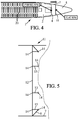
- Fig. 4 shows the location of a flat rear pressure bulkhead in an airplane according to an embodiment of the invention, as compared to the location of a curved rear pressure bulkhead in an airplane according to previous first prior art.
- FIG 4 in a classical configuration according to first prior art, there is an airplane 1 comprising a cabin 2 filled with passengers seats 20 and a tail 5 separated from each other by a curved rear pressure bulkhead 4 presenting resistance to air pressure coming from the inside of cabin 2.
- the curved rear pressure bulkhead 4 is attached to the fuselage wall 7.
- FIG 4 in a new configuration according to an embodiment of the invention, there is an airplane 1 comprising a cabin 2 filled with passengers seats 20 and a tail 5 separated from each other by a flat rear pressure bulkhead 11 presenting resistance to air pressure coming from the inside of cabin 2.
- This flat rear pressure bulkhead 11 replaces the classical curved rear pressure bulkhead 4 according to first prior art.
- the flat rear pressure bulkhead 11 is attached to the fuselage wall 7.
- the flat rear pressure bulkhead 11 has been moved towards the rear of the airplane 1, as compared to the curved rear pressure bulkhead 4 of first prior art, in order to gain space for the cabin 2, in order to be able to add at least one row of seats in an airplane 1 of middle size, for example 6 or 8 seats more in a plane comprising about 150 seats, what will roughly increase the revenue of each flight by 5%, at practically no increase of costs.
- a preferred flat rear pressure bulkhead 11, for a middle sized airplane as for example A320 Airbus (registered trademark), will preferably present a thickness in the longitudinal direction of the airplane 1 which will be comprised between 350mm and 400mm.
- This preferred flat rear pressure bulkhead 11 will preferably present a global weight comprised between 100kg and 130kg, with a density between 10kg/m 2 and 13kg/m 2 , on a global surface of about 10m 2 .
- the load to be applied on this preferred flat rear pressure bulkhead 11 will be between 0.11 and 0.12 MPa.
- Fig. 5 shows a side view of an example of an aircraft flat rear pressure bulkhead according to an embodiment of the invention.
- the flat rear pressure bulkhead 11 presents the structure of a layer stacking, successively including, from forward to backward in the longitudinal direction of the airplane or of the aircraft, an airtight membrane 12, a layer of front flanges 14, a layer of orthogonal reinforcement grid 13, a layer of rear flanges 14.
- the flat rear pressure bulkhead 11 is encircled by a circular ring 15 attached to fuselage wall 7 via attachments 8.
- the airtight membrane 12 is made of aluminum or made of plastic, its function is to keep the air pressure in the aircraft cabin.
- the airtight membrane 12 has the function of keeping an airtight separating wall between cabin and tail in the aircraft.
- the layer of orthogonal reinforcement grid 13 is a lattice of reinforcement cells presenting polygonal shapes, preferably hexagonal shapes. Their function is to carry the pressure load coming from the airtight membrane 12, through the front layer of flanges 14, while stiffening the airtight membrane 12, and to transmit this pressure load partly to the rear layer of flanges 14.
- the circular ring 15 encircling the layer stacking stiffens this layer stacking while providing for a rigid structure to be attached to fuselage wall, thereby connecting layer stacking to fuselage wall 7.
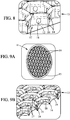
- Fig. 6A shows a perspective view of an example of the structure of the layer stacking of an aircraft flat rear pressure bulkhead according to a first embodiment of the invention, showing interface and reinforcement grid made in one piece.
- Fig. 6B shows a perspective view of a detail of figure 6A .
- the reinforcement grid 13 is a lattice of hexagonal reinforcement cells 17 made in one piece with the layer of front flanges 14 on one side and with the layer of rear flanges 14 on the other side.
- the layer of front flanges 14 makes the interface with the airtight membrane 12.
- the cross section 16 of this one piece structure is I shaped.
- One horizontal bar of this I shape provides for distributing the strain of the grid 13 over the surface of the membrane 12.
- the vertical bar of this I shape, constituting part of the grid 13 provides for carrying the load transmitted by the membrane 12 to the rear layer of flanges 14 which constitutes another part of the grid 13 increasing the inertia of this grid 13.
- Holes 18 are provided to reduce the weight.
- Fig. 7A shows a perspective view of an example of the structure of the layer stacking of an aircraft flat rear pressure bulkhead according to a second embodiment of the invention, showing interface and reinforcement grid made in one piece.
- Fig. 7B shows a perspective view of a detail of figure 7A .
- the reinforcement grid 13 is a lattice of hexagonal reinforcement cells 17 made in one piece with the layer of front flanges 14 on one side and with the layer of rear flanges 14 on the other side.
- the layer of front flanges 14 makes the interface with the airtight membrane 12.
- the cross section 16 of this one piece structure is Y shaped on the rear side but remains T shaped on the front side.
- the horizontal bar of this T shape provides for distributing the strain of the grid 13 over the surface of the membrane 12.
- the vertical bar of this Y shape, constituting part of the grid 13 provides for carrying the load transmitted by the membrane 12 to the rear layer of flanges 14 which constitutes another part of the grid 13 increasing the inertia of this grid 13.
- Holes 18 are provided to reduce the weight.
- Fig. 8 shows a perspective view of an example of the structure of the layer stacking of an aircraft flat rear pressure bulkhead according to a third embodiment of the invention, showing interface and reinforcement grid made in one piece.
- the reinforcement grid 13 is a lattice of hexagonal reinforcement cells 17 made in one piece with the layer of front flanges 14 on one side and with the layer of rear flanges 14 on the other side.
- the layer of front flanges 14 makes the interface with the airtight membrane 12.
- the cross section 16 of this one piece structure is tube shaped on the rear side but remains T shaped on the front side.
- the horizontal bar of this T shape provides for distributing the strain of the grid 13 over the surface of the membrane 12.
- the vertical bar, constituting part of the grid 13 provides for carrying the load transmitted by the membrane 12 to the rear layer of flanges 14 which are tube shaped, this rear layer of flanges 14 constitutes another part of the grid 13 increasing the inertia of this grid 13. Holes 18 are provided to reduce the weight.
- Fig. 9A shows a perspective view of an example of the structure of the layer stacking of an aircraft flat rear pressure bulkhead according to a fourth embodiment of the invention, showing interface and reinforcement grid made in one piece.
- Fig. 9B shows a perspective view of a detail of figure 9A .
- the flat rear pressure bulkhead 11 comprises a lattice of membrane domes 19 encircled by the circular ring 15.
- the reinforcement grid 13 is a lattice of hexagonal reinforcement cells 17 made in one piece with the layer of front flanges 14 on one side and with the layer of rear flanges 14 on the other side.
- the layer of front flanges 14 makes the interface with the airtight dome shaped membrane cells which are domes 19.
- the cross section 16 of this one piece structure is tube shaped on the rear side but is V shaped on the front side.
- the membrane domes 19 are attached to the tip of this V shaped front flanges 14.
- the vertical bar constituting part of the grid 13, provides for carrying the load transmitted by the membrane domes 19 to the rear layer of flanges 14 which are tube shaped, this rear layer of flanges 14 constitutes another part of the grid 13 increasing the inertia of this grid 13. Holes 18 are provided to reduce the weight.
Landscapes
- Engineering & Computer Science (AREA)
- Mechanical Engineering (AREA)
- Aviation & Aerospace Engineering (AREA)
- Laminated Bodies (AREA)
Abstract
Description
- The invention relates to the field of rear pressure bulkheads in aircrafts and especially in airplanes.
- An aircraft rear pressure bulkhead is an airtight wall separating the cabin of the aircraft from the tail of the aircraft. An aircraft rear pressure bulkhead aims at sealing the rear part of the aircraft in order to maintain the cabin pressure in the aircraft.
- According to a first prior art, it is known a curved rear pressure bulkhead at the rear of an airplane. This curved rear pressure bulkhead is robust with a good resistance to air pressure coming from cabin inside and presents a reduced global weight. Besides, the small angle made by the external periphery of the curved rear pressure bulkhead with the mean surface of the airplane fuselage to which it is attached leads to a better stress distribution on the whole of the curved rear pressure bulkhead and as well a better load transfer to the skin of the fuselage. However, this curved rear pressure bulkhead takes a substantial volume to be implemented at the rear of the airplane.
- Such a first prior art is for example represented on
figures 1 and 2 . Onfigure 1 , there is an airplane 1 comprising acabin 2 and atail 5 separated from each other by a curvedrear pressure bulkhead 4 presenting resistance toair pressure 3 coming from the inside ofcabin 2. The curvedrear pressure bulkhead 4 is attached byattachments 8 to thefuselage wall 7, making an angle which is quite small, thereby better load distributing from on the whole surface of the curvedrear pressure bulkhead 4 to the skin of the fuselage. - According to a second prior art, it is known a flat rear pressure bulkhead at the rear of an airplane. To make this flat rear pressure bulkhead robust enough, it comprises thick horizontal and vertical reinforcement beams crossed with one another. However, these thick horizontal and vertical reinforcement beams present two drawbacks. First, these thick reinforcement bars increase notably the global weight of this flat rear pressure bulkhead. Second, these thick reinforcement bars notably increase the thickness of this rear pressure bulkhead, thereby taking a non-negligible volume to be implemented at the rear of the airplane. Moreover, air pressure distribution into the flat rear pressure bulkhead implies a worst stress distribution in it.
- Such a second prior art is for example represented on
figure 3 . Onfigure 3 , there is aflat panel 6 supported by thick horizontal andvertical reinforcements beams 9, crossing with one another, making a waffle bulkhead pattern of theflat panel 6 presenting about a dozen ofsquares 10. Thethick reinforcement beams 9 present the drawbacks to increase simultaneously the weight, the thickness and the volume of this global flatrear pressure bulkhead 4. - The object of the present invention is to alleviate at least partly the above mentioned drawbacks.
- More particularly, the invention aims at providing for a rear pressure bulkhead which will go towards a first compromise which simultaneously allows for gaining some place as compared to a classical curved rear pressure bulkhead according to first prior art while keeping a comparable resistance to cabin air pressure as this classical curved rear pressure bulkhead, and towards a second compromise which allows for keeping a comparable resistance to cabin air pressure as the flat rear pressure bulkhead according to second prior art while presenting reduced weight and volume as compared to this flat rear pressure bulkhead.
- The invention proposes a rear pressure bulkhead which will present an improved global compromise between its robustness, i.e. resistance to cabin air pressure, its weight and its filled volume, i.e. especially its thickness corresponding to volume in the longitudinal direction of the aircraft or the airplane.
- The invention proposes on the one hand to make a flat rear pressure bulkhead in order to give more space to passengers in cabin and for example to gain thereby at least one passenger row of seats in the cabin in case of an airplane, while on the other hand keeping a good compromise between its robustness and its weight and its thickness, by modifying its structure to make it rather robust, light and compact.
- This object is achieved with an aircraft flat rear pressure bulkhead, having a layered stacking including: an airtight membrane, a honeycombed reinforcement grid, an interface in between distributing grid strain over membrane surface.
- This object is also achieved with an aircraft flat rear pressure bulkhead, including: a honeycombed reinforcement grid, airtight membranes respectively filling honeycombs of said honeycombed reinforcement grid, said honeycombs preferably being polygonal honeycombs with at least six sides, and more preferably being hexagonal honeycombs.
- Preferred embodiments comprise one or more of the following features, which can be taken separately or together, either in partial combination or in full combination, associated to one or the other of previous objects of the invention.
- Preferably, said honeycombed reinforcement grid comprises at least 40 honeycombs, preferably at least 50 honeycombs. The number of noneycombs may also depend on the size of the aircraft and the difference the pressure between the atmosphere and the cabin. Thus, increasing the number of the reinforcements cells in the lattice of the grid increases grid resistance to air pressure. Besides, making numerous reinforcements cells in the lattice of the grid allows for decreasing the individual resistance of each single cell thereby helping keeping to a limited and reasonable amount the material quantity as well as the global weight of the flat rear pressure bulkhead. Thus, the compromise between increased robustness and limited weight is improved.
- Preferably, a largest dimension of most of, preferably of all of, honeycombs of said honeycombed reinforcement grid, is less than 500mm, preferably less than 450mm. Thus, having a small dimension of each reinforcement cell allows for a good support of most of the surface of the airtight membrane, thereby again increasing resistance to cabin air pressure while keeping limited the global weight of the flat rear pressure bulkhead.
- Preferably, most of, preferably of all of, honeycombs of said honeycombed reinforcement grid, are polygonal honeycombs with at least six sides, are preferably hexagonal honeycombs. Thus, the ratio between the intrinsic resistance of the reinforcement grid and its weight is improved, simply because of the type of geometrical pattern used while keeping roughly the same quantity of material to make this reinforcement grid. Thus, again, the compromise between robustness and weight of the flat rear pressure bulkhead is improved.
- Preferably, honeycomb walls of said honeycombed reinforcement grid are orthogonal to membrane mean surface. Thus, their strength to support the airtight membrane is maximal, for a given amount of material hence for a given weight. Once more, the compromise between robustness and weight of the flat rear pressure bulkhead is improved.
- Preferably, said membrane is flat and parallel to mean surface of flat rear pressure bulkhead. Thus, the occupied volume of the membrane is reduced, and hence the global volume of the flat rear pressure bulkhead is reduced too.
- Preferably, said interface comprises, preferably is constituted of, flanges distributing grid strain over membrane surface. This happens to be practically as robust as reinforcement beams, provided, there is a sufficient density of such flanges all over the surface of the membrane, linked to a sufficient density of reinforcement cells, and this can be achieved with a reduced amount of material, and hence with a reduced weight, since these flanges are smaller structures than reinforcement bars. Once more, the compromise between robustness and weight of the flat rear pressure bulkhead is improved.
- Preferably, said reinforcement grid also comprises, on its rear face opposite to its front face contacting said interface, another layer of flanges reinforcing honeycombs. Thus, robustness of grid is still increased, therefore global robustness of flat rear pressure bulkhead is also increased.
- Preferably, said flanges are flat and parallel to membrane mean surface. Thus, their support effect with respect to membrane is improved. The support effect helps interface better distributing grid strain over membrane surface. The flanges with this orientation can present a limited extension, while keeping a good support effect with respect to membrane. This type of flanges will thereby require a limited amount of material, thus again reducing global weight of flat rear pressure bulkhead.
- Preferably, said flanges are tubes with axis parallel to membrane mean surface. The compromise between robustness and weight of this reinforcement grid and interface is improved, but the support effect with respect to membrane is more limited because of the reduced surface of interface being directly in contact with membrane.
- Preferably, said interface and said honeycombed reinforcement grid are manufactured in one single piece. This makes the resulting one piece structure comprising grid and interface more robust, with no added material therefore no added weight.
- Preferably, a cross section of said one piece layer is T shaped or I shaped or Y shaped. T shaped cross section appears to be the better, at least with respect to support effect provided by interface to membrane.
- Preferably, said flat rear pressure bulkhead is a disk. This allows this flat rear pressure bulkhead to fill completely the available space within the rear of the aircraft and to be directly attached to fuselage wall or at least in the vicinity of fuselage wall.
- Preferably, said layered stacking is encircled by a circular ring to be fixed to aircraft fuselage attachments. This circular ring first improves global robustness of flat rear pressure bulkhead and second makes it easier for implementation.
- Preferably, in an embodiment, said membrane is a plastic membrane. This allows for reducing somewhat more the global weight of the flat rear pressure bulkhead. This can be done because of the high robustness of the new structure of the layer staking forming the flat rear pressure bulkhead, and especially because of the high support effect of this new structure with respect to the membrane.
- Preferably, in another embodiment, said membrane is a metallic membrane. This allows for increasing somewhat more the global robustness of the flat rear pressure bulkhead.
- Preferably, said flat rear pressure bulkhead largest thickness is less than 400mm. The layer stacking structure allows for such a limited thickness while not giving up robustness.
- Preferably, said airtight membranes are dome shaped. Thus, their specific shape improves robustness and resistance to cabin air pressure while not deteriorating global weight of flat rear pressure bulkhead.
- Further features and advantages of the invention will appear from the following description of embodiments of the invention, given as non-limiting examples, with reference to the accompanying drawings listed hereunder.
-
-
Fig. 1 shows a curved rear pressure bulkhead in an airplane, according to a first prior art. -
Fig. 2 shows specific attachment of the curved rear pressure bulkhead offigure 1 to the fuselage wall of the airplane, according to this first prior art. -
Fig. 3 shows a flat rear pressure bulkhead in an airplane, according to a second prior art. -
Fig. 4 shows the location of a flat rear pressure bulkhead in an airplane according to an embodiment of the invention, as compared to the location of a curved rear pressure bulkhead in an airplane according to previous first prior art. -
Fig. 5 shows a side view of an example of an aircraft flat rear pressure bulkhead according to an embodiment of the invention. -
Fig. 6A shows a perspective view of an example of the structure of the layer stacking of an aircraft flat rear pressure bulkhead according to a first embodiment of the invention, showing interface and reinforcement grid made in one piece. -
Fig. 6B shows a perspective view of a detail offigure 6A . -
Fig. 7A shows a perspective view of an example of the structure of the layer stacking of an aircraft flat rear pressure bulkhead according to a second embodiment of the invention, showing interface and reinforcement grid made in one piece. -
Fig. 7B shows a perspective view of a detail offigure 7A . -
Fig. 8 shows a perspective view of an example of the structure of the layer stacking of an aircraft flat rear pressure bulkhead according to a third embodiment of the invention, showing interface and reinforcement grid made in one piece. -
Fig. 9A shows a perspective view of an example of the structure of the layer stacking of an aircraft flat rear pressure bulkhead according to a fourth embodiment of the invention, showing interface and reinforcement grid made in one piece. -
Fig. 9B shows a perspective view of a detail offigure 9A . -
Fig. 4 shows the location of a flat rear pressure bulkhead in an airplane according to an embodiment of the invention, as compared to the location of a curved rear pressure bulkhead in an airplane according to previous first prior art. - On
figure 4 , in a classical configuration according to first prior art, there is an airplane 1 comprising acabin 2 filled withpassengers seats 20 and atail 5 separated from each other by a curvedrear pressure bulkhead 4 presenting resistance to air pressure coming from the inside ofcabin 2. The curvedrear pressure bulkhead 4 is attached to thefuselage wall 7. - On
figure 4 , in a new configuration according to an embodiment of the invention, there is an airplane 1 comprising acabin 2 filled withpassengers seats 20 and atail 5 separated from each other by a flatrear pressure bulkhead 11 presenting resistance to air pressure coming from the inside ofcabin 2. This flatrear pressure bulkhead 11 replaces the classical curvedrear pressure bulkhead 4 according to first prior art. The flatrear pressure bulkhead 11 is attached to thefuselage wall 7. The flatrear pressure bulkhead 11 has been moved towards the rear of the airplane 1, as compared to the curvedrear pressure bulkhead 4 of first prior art, in order to gain space for thecabin 2, in order to be able to add at least one row of seats in an airplane 1 of middle size, for example 6 or 8 seats more in a plane comprising about 150 seats, what will roughly increase the revenue of each flight by 5%, at practically no increase of costs. - A preferred flat
rear pressure bulkhead 11, for a middle sized airplane as for example A320 Airbus (registered trademark), will preferably present a thickness in the longitudinal direction of the airplane 1 which will be comprised between 350mm and 400mm. This preferred flatrear pressure bulkhead 11 will preferably present a global weight comprised between 100kg and 130kg, with a density between 10kg/m2 and 13kg/m2, on a global surface of about 10m2. The load to be applied on this preferred flatrear pressure bulkhead 11 will be between 0.11 and 0.12 MPa. -
Fig. 5 shows a side view of an example of an aircraft flat rear pressure bulkhead according to an embodiment of the invention. - The flat
rear pressure bulkhead 11 presents the structure of a layer stacking, successively including, from forward to backward in the longitudinal direction of the airplane or of the aircraft, anairtight membrane 12, a layer offront flanges 14, a layer oforthogonal reinforcement grid 13, a layer ofrear flanges 14. The flatrear pressure bulkhead 11 is encircled by acircular ring 15 attached tofuselage wall 7 viaattachments 8. - The
airtight membrane 12 is made of aluminum or made of plastic, its function is to keep the air pressure in the aircraft cabin. Theairtight membrane 12 has the function of keeping an airtight separating wall between cabin and tail in the aircraft. - The layer of
orthogonal reinforcement grid 13 is a lattice of reinforcement cells presenting polygonal shapes, preferably hexagonal shapes. Their function is to carry the pressure load coming from theairtight membrane 12, through the front layer offlanges 14, while stiffening theairtight membrane 12, and to transmit this pressure load partly to the rear layer offlanges 14. - The
circular ring 15 encircling the layer stacking stiffens this layer stacking while providing for a rigid structure to be attached to fuselage wall, thereby connecting layer stacking tofuselage wall 7. -
Fig. 6A shows a perspective view of an example of the structure of the layer stacking of an aircraft flat rear pressure bulkhead according to a first embodiment of the invention, showing interface and reinforcement grid made in one piece.Fig. 6B shows a perspective view of a detail offigure 6A . - The
reinforcement grid 13 is a lattice ofhexagonal reinforcement cells 17 made in one piece with the layer offront flanges 14 on one side and with the layer ofrear flanges 14 on the other side. The layer offront flanges 14 makes the interface with theairtight membrane 12. Thecross section 16 of this one piece structure is I shaped. One horizontal bar of this I shape provides for distributing the strain of thegrid 13 over the surface of themembrane 12. The vertical bar of this I shape, constituting part of thegrid 13, provides for carrying the load transmitted by themembrane 12 to the rear layer offlanges 14 which constitutes another part of thegrid 13 increasing the inertia of thisgrid 13.Holes 18 are provided to reduce the weight. -
Fig. 7A shows a perspective view of an example of the structure of the layer stacking of an aircraft flat rear pressure bulkhead according to a second embodiment of the invention, showing interface and reinforcement grid made in one piece.Fig. 7B shows a perspective view of a detail offigure 7A . - The
reinforcement grid 13 is a lattice ofhexagonal reinforcement cells 17 made in one piece with the layer offront flanges 14 on one side and with the layer ofrear flanges 14 on the other side. The layer offront flanges 14 makes the interface with theairtight membrane 12. Thecross section 16 of this one piece structure is Y shaped on the rear side but remains T shaped on the front side. The horizontal bar of this T shape provides for distributing the strain of thegrid 13 over the surface of themembrane 12. The vertical bar of this Y shape, constituting part of thegrid 13, provides for carrying the load transmitted by themembrane 12 to the rear layer offlanges 14 which constitutes another part of thegrid 13 increasing the inertia of thisgrid 13.Holes 18 are provided to reduce the weight. -
Fig. 8 shows a perspective view of an example of the structure of the layer stacking of an aircraft flat rear pressure bulkhead according to a third embodiment of the invention, showing interface and reinforcement grid made in one piece. - The
reinforcement grid 13 is a lattice ofhexagonal reinforcement cells 17 made in one piece with the layer offront flanges 14 on one side and with the layer ofrear flanges 14 on the other side. The layer offront flanges 14 makes the interface with theairtight membrane 12. Thecross section 16 of this one piece structure is tube shaped on the rear side but remains T shaped on the front side. The horizontal bar of this T shape provides for distributing the strain of thegrid 13 over the surface of themembrane 12. The vertical bar, constituting part of thegrid 13, provides for carrying the load transmitted by themembrane 12 to the rear layer offlanges 14 which are tube shaped, this rear layer offlanges 14 constitutes another part of thegrid 13 increasing the inertia of thisgrid 13.Holes 18 are provided to reduce the weight. -
Fig. 9A shows a perspective view of an example of the structure of the layer stacking of an aircraft flat rear pressure bulkhead according to a fourth embodiment of the invention, showing interface and reinforcement grid made in one piece.Fig. 9B shows a perspective view of a detail offigure 9A . - The flat
rear pressure bulkhead 11 comprises a lattice ofmembrane domes 19 encircled by thecircular ring 15. Thereinforcement grid 13 is a lattice ofhexagonal reinforcement cells 17 made in one piece with the layer offront flanges 14 on one side and with the layer ofrear flanges 14 on the other side. The layer offront flanges 14 makes the interface with the airtight dome shaped membrane cells which are domes 19. Thecross section 16 of this one piece structure is tube shaped on the rear side but is V shaped on the front side. The membrane domes 19 are attached to the tip of this V shapedfront flanges 14. The vertical bar, constituting part of thegrid 13, provides for carrying the load transmitted by the membrane domes 19 to the rear layer offlanges 14 which are tube shaped, this rear layer offlanges 14 constitutes another part of thegrid 13 increasing the inertia of thisgrid 13.Holes 18 are provided to reduce the weight. - The invention has been described with reference to preferred embodiments. However, many variations are possible within the scope of the invention.
Claims (20)
- Aircraft flat rear pressure bulkhead, having a layered stacking including:an airtight membrane (12),
 a honeycombed reinforcement grid (13),
 an interface (14) in between distributing grid (13) strain over membrane (12) surface.
- Aircraft flat rear pressure bulkhead according to claim 1, wherein said honeycombed reinforcement grid (13) comprises at least 40 honeycombs (17), preferably at least 50 honeycombs (17).
- Aircraft flat rear pressure bulkhead according to any preceding claim, wherein a largest dimension of most of, preferably of all of, honeycombs (17) of said honeycombed reinforcement grid (13), is less than 500mm, preferably less than 450mm.
- Aircraft flat rear pressure bulkhead according to any preceding claim, wherein most of, preferably of all of, honeycombs (17) of said honeycombed reinforcement grid (13), are polygonal honeycombs (17) with at least six sides, are preferably hexagonal honeycombs (17).
- Aircraft flat rear pressure bulkhead according to any preceding claim, wherein honeycomb walls (16) of said honeycombed reinforcement grid (13) are orthogonal to membrane (12) mean surface.
- Aircraft flat rear pressure bulkhead according to any preceding claim, wherein said membrane (12) is flat and parallel to mean surface of flat rear pressure bulkhead.
- Aircraft flat rear pressure bulkhead according to any preceding claim, wherein said interface (14) comprises, preferably is constituted of, flanges (14) distributing grid (13) strain over membrane (12) surface.
- Aircraft flat rear pressure bulkhead according to any preceding claim, wherein said reinforcement grid (13) also comprises, on its rear face opposite to its front face contacting said interface, another layer of flanges (14) reinforcing honeycombs (17).
- Aircraft flat rear pressure bulkhead according to claim 7 or 8, wherein said flanges (14) are flat and parallel to membrane (12) mean surface.
- Aircraft flat rear pressure bulkhead according to claim 7 or 8, wherein said flanges (14) are tubes with axis parallel to membrane (12) mean surface.
- Aircraft flat rear pressure bulkhead according to any preceding claim, wherein said interface (14) and said honeycombed reinforcement grid (13) are manufactured in one piece.
- Aircraft flat rear pressure bulkhead according to claim 11, wherein a cross section (16) of said one piece layer is T shaped or I shaped or Y shaped.
- Aircraft flat rear pressure bulkhead according to any preceding claim, wherein said flat rear pressure bulkhead is a disk.
- Aircraft flat rear pressure bulkhead according to claim 13, wherein said layered stacking is encircled by a circular ring (15) to be fixed to aircraft fuselage attachments (8).
- Aircraft flat rear pressure bulkhead according to any preceding claim, wherein said membrane (12) is a plastic membrane.
- Aircraft flat rear pressure bulkhead according to any of claims 1 to 14, wherein said membrane (12) is a metallic membrane.
- Aircraft flat rear pressure bulkhead according to any preceding claim, wherein said flat rear pressure bulkhead largest thickness is less than 400mm.
- Aircraft flat rear pressure bulkhead, including:a honeycombed reinforcement grid (13),
 airtight membranes (19) respectively filling honeycombs (17) of said honeycombed reinforcement grid (13), said honeycombs (17) preferably being polygonal honeycombs (17) with at least six sides, and more preferably being hexagonal honeycombs (17).
- Aircraft flat rear pressure bulkhead according to claim 18, wherein said honeycombed reinforcement grid (13) comprises at least 40 honeycombs (17), preferably at least 50 honeycombs (17).
- Aircraft flat rear pressure bulkhead according to claim 18 or 19, wherein
said airtight membranes (19) are dome shaped.
Priority Applications (1)
| Application Number | Priority Date | Filing Date | Title |
|---|---|---|---|
| EP16382656.3A EP3342700B1 (en) | 2016-12-27 | 2016-12-27 | Rear pressure bulkhead |
Applications Claiming Priority (1)
| Application Number | Priority Date | Filing Date | Title |
|---|---|---|---|
| EP16382656.3A EP3342700B1 (en) | 2016-12-27 | 2016-12-27 | Rear pressure bulkhead |
Publications (2)
| Publication Number | Publication Date |
|---|---|
| EP3342700A1 true EP3342700A1 (en) | 2018-07-04 |
| EP3342700B1 EP3342700B1 (en) | 2020-04-22 |
Family
ID=57714496
Family Applications (1)
| Application Number | Title | Priority Date | Filing Date |
|---|---|---|---|
| EP16382656.3A Active EP3342700B1 (en) | 2016-12-27 | 2016-12-27 | Rear pressure bulkhead |
Country Status (1)
| Country | Link |
|---|---|
| EP (1) | EP3342700B1 (en) |
Cited By (1)
| Publication number | Priority date | Publication date | Assignee | Title |
|---|---|---|---|---|
| CN114771803A (en) * | 2022-06-20 | 2022-07-22 | 中国飞机强度研究所 | Composite wallboard structure made of impact-resistant foam metal composite material for aircraft manufacturing |
Families Citing this family (3)
| Publication number | Priority date | Publication date | Assignee | Title |
|---|---|---|---|---|
| EP4596394A1 (en) * | 2024-01-30 | 2025-08-06 | Airbus Operations GmbH | Pressure bulkhead device, aircraft fuselage and aircraft |
| EP4613636A1 (en) * | 2024-03-04 | 2025-09-10 | Airbus Operations GmbH | Flat bulkheads, an aircraft, and a method of producing a flat bulkhead |
| EP4752045A1 (en) * | 2024-11-29 | 2026-06-03 | Airbus Operations (S.A.S.) | Flexible pressure bulkhead for an aircraft |
Citations (5)
| Publication number | Priority date | Publication date | Assignee | Title |
|---|---|---|---|---|
| DE102006029231A1 (en) * | 2006-06-26 | 2008-01-03 | Airbus Deutschland Gmbh | Pressure bulkhead for e.g. securing pressure tight inner side in tail section of aircraft, has frame carrying bulkhead main section and netlike unit with strip units that are interlaced strips, which forms fabric in air-tight manner |
| US20080179459A1 (en) * | 2007-01-30 | 2008-07-31 | Airbus Espana, S.L. | Pressure bulkhead made of composite material for an aircraft |
| EP2700573A2 (en) * | 2012-08-22 | 2014-02-26 | Airbus Operations GmbH | A pressurized airplane fuselage, comprising a pressure bulkhead |
| US20160264231A1 (en) * | 2015-03-09 | 2016-09-15 | The Boeing Company | Fused Porogen Process for Acoustic Septa Fabrication |
| EP3095689A1 (en) * | 2015-05-20 | 2016-11-23 | Airbus Operations GmbH | A pressure bulkhead for an aircraft fuselage, and an aircraft comprising such a pressure bulkhead |
-
2016
- 2016-12-27 EP EP16382656.3A patent/EP3342700B1/en active Active
Patent Citations (5)
| Publication number | Priority date | Publication date | Assignee | Title |
|---|---|---|---|---|
| DE102006029231A1 (en) * | 2006-06-26 | 2008-01-03 | Airbus Deutschland Gmbh | Pressure bulkhead for e.g. securing pressure tight inner side in tail section of aircraft, has frame carrying bulkhead main section and netlike unit with strip units that are interlaced strips, which forms fabric in air-tight manner |
| US20080179459A1 (en) * | 2007-01-30 | 2008-07-31 | Airbus Espana, S.L. | Pressure bulkhead made of composite material for an aircraft |
| EP2700573A2 (en) * | 2012-08-22 | 2014-02-26 | Airbus Operations GmbH | A pressurized airplane fuselage, comprising a pressure bulkhead |
| US20160264231A1 (en) * | 2015-03-09 | 2016-09-15 | The Boeing Company | Fused Porogen Process for Acoustic Septa Fabrication |
| EP3095689A1 (en) * | 2015-05-20 | 2016-11-23 | Airbus Operations GmbH | A pressure bulkhead for an aircraft fuselage, and an aircraft comprising such a pressure bulkhead |
Cited By (1)
| Publication number | Priority date | Publication date | Assignee | Title |
|---|---|---|---|---|
| CN114771803A (en) * | 2022-06-20 | 2022-07-22 | 中国飞机强度研究所 | Composite wallboard structure made of impact-resistant foam metal composite material for aircraft manufacturing |
Also Published As
| Publication number | Publication date |
|---|---|
| EP3342700B1 (en) | 2020-04-22 |
Similar Documents
| Publication | Publication Date | Title |
|---|---|---|
| EP3342700B1 (en) | Rear pressure bulkhead | |
| US20150336680A1 (en) | Tank System For The Cryogenic Storage Of Hydrogen, And Aircraft With A Tank System For The Cryogenic Storage Of Hydrogen | |
| US9266597B1 (en) | Aerostructure for rigid body airship | |
| EP0854821B1 (en) | Hybrid aircraft | |
| CN103429493B (en) | Rhombus aircraft window for composite and/or metal fuselage | |
| CN101801783B (en) | Pressure bulkhead and method for subdivision of an aircraft or spacecraft | |
| EP2876042B1 (en) | Helicopter airframe | |
| US20220089269A1 (en) | Large-Scale Semi-Rigid Structure Airship | |
| CN110294097B (en) | Novel energy-absorbing buffering of cell honeycomb device | |
| US20190112034A1 (en) | Aircraft landing gear bay roof comprising an inclined aft bulkhead | |
| EP1292474A1 (en) | Hybrid air vehicle | |
| EP4124568A1 (en) | Aircraft with hydrogen tank | |
| CN101489868A (en) | Aircraft tail cone | |
| EP3760534B1 (en) | Pressure vessel having substantially flat panel | |
| GB2638957A (en) | An electric aircraft | |
| CN104859839A (en) | Composite structural element and torsion box | |
| CN111301717A (en) | Bulkhead structure of manned spacecraft sealed cabin | |
| US20190389592A1 (en) | Modular subfloor arrangement for an aircraft | |
| KR20150079431A (en) | Subfloor structure with an integral hull for a rotary wing aircraft | |
| CN104276272B (en) | Pressure plare and the aircraft including the pressure plare | |
| US20190185129A1 (en) | Pressure Bulkhead For A Pressurized Cabin Of An Aerospace Craft, And An Aerospace Craft | |
| Mukhopadhyay et al. | Composite structure modeling and analysis of advanced aircraft fuselage concepts | |
| EP3059156B1 (en) | Flat kinked rear pressure bulkhead | |
| CN212797284U (en) | Airtight end frame structure in integral aircraft plane | |
| Mukhopadhyay | Hybrid-wing-body vehicle composite fuselage analysis and case study |
Legal Events
| Date | Code | Title | Description |
|---|---|---|---|
| PUAI | Public reference made under article 153(3) epc to a published international application that has entered the european phase |
Free format text: ORIGINAL CODE: 0009012 |
|
| STAA | Information on the status of an ep patent application or granted ep patent |
Free format text: STATUS: THE APPLICATION HAS BEEN PUBLISHED |
|
| AK | Designated contracting states |
Kind code of ref document: A1 Designated state(s): AL AT BE BG CH CY CZ DE DK EE ES FI FR GB GR HR HU IE IS IT LI LT LU LV MC MK MT NL NO PL PT RO RS SE SI SK SM TR |
|
| AX | Request for extension of the european patent |
Extension state: BA ME |
|
| STAA | Information on the status of an ep patent application or granted ep patent |
Free format text: STATUS: REQUEST FOR EXAMINATION WAS MADE |
|
| 17P | Request for examination filed |
Effective date: 20190104 |
|
| RBV | Designated contracting states (corrected) |
Designated state(s): AL AT BE BG CH CY CZ DE DK EE ES FI FR GB GR HR HU IE IS IT LI LT LU LV MC MK MT NL NO PL PT RO RS SE SI SK SM TR |
|
| GRAP | Despatch of communication of intention to grant a patent |
Free format text: ORIGINAL CODE: EPIDOSNIGR1 |
|
| STAA | Information on the status of an ep patent application or granted ep patent |
Free format text: STATUS: GRANT OF PATENT IS INTENDED |
|
| INTG | Intention to grant announced |
Effective date: 20191111 |
|
| RIN1 | Information on inventor provided before grant (corrected) |
Inventor name: PARPAL, NICOLAS Inventor name: VILLACIEROS, LUIS Inventor name: GONZALEZ, JUAN MIGUEL |
|
| GRAS | Grant fee paid |
Free format text: ORIGINAL CODE: EPIDOSNIGR3 |
|
| GRAA | (expected) grant |
Free format text: ORIGINAL CODE: 0009210 |
|
| STAA | Information on the status of an ep patent application or granted ep patent |
Free format text: STATUS: THE PATENT HAS BEEN GRANTED |
|
| AK | Designated contracting states |
Kind code of ref document: B1 Designated state(s): AL AT BE BG CH CY CZ DE DK EE ES FI FR GB GR HR HU IE IS IT LI LT LU LV MC MK MT NL NO PL PT RO RS SE SI SK SM TR |
|
| REG | Reference to a national code |
Ref country code: CH Ref legal event code: EP |
|
| REG | Reference to a national code |
Ref country code: IE Ref legal event code: FG4D |
|
| REG | Reference to a national code |
Ref country code: DE Ref legal event code: R096 Ref document number: 602016034450 Country of ref document: DE |
|
| REG | Reference to a national code |
Ref country code: AT Ref legal event code: REF Ref document number: 1259737 Country of ref document: AT Kind code of ref document: T Effective date: 20200515 |
|
| REG | Reference to a national code |
Ref country code: LT Ref legal event code: MG4D |
|
| REG | Reference to a national code |
Ref country code: NL Ref legal event code: MP Effective date: 20200422 |
|
| PG25 | Lapsed in a contracting state [announced via postgrant information from national office to epo] |
Ref country code: GR Free format text: LAPSE BECAUSE OF FAILURE TO SUBMIT A TRANSLATION OF THE DESCRIPTION OR TO PAY THE FEE WITHIN THE PRESCRIBED TIME-LIMIT Effective date: 20200723 Ref country code: NO Free format text: LAPSE BECAUSE OF FAILURE TO SUBMIT A TRANSLATION OF THE DESCRIPTION OR TO PAY THE FEE WITHIN THE PRESCRIBED TIME-LIMIT Effective date: 20200722 Ref country code: PT Free format text: LAPSE BECAUSE OF FAILURE TO SUBMIT A TRANSLATION OF THE DESCRIPTION OR TO PAY THE FEE WITHIN THE PRESCRIBED TIME-LIMIT Effective date: 20200824 Ref country code: SE Free format text: LAPSE BECAUSE OF FAILURE TO SUBMIT A TRANSLATION OF THE DESCRIPTION OR TO PAY THE FEE WITHIN THE PRESCRIBED TIME-LIMIT Effective date: 20200422 Ref country code: LT Free format text: LAPSE BECAUSE OF FAILURE TO SUBMIT A TRANSLATION OF THE DESCRIPTION OR TO PAY THE FEE WITHIN THE PRESCRIBED TIME-LIMIT Effective date: 20200422 Ref country code: NL Free format text: LAPSE BECAUSE OF FAILURE TO SUBMIT A TRANSLATION OF THE DESCRIPTION OR TO PAY THE FEE WITHIN THE PRESCRIBED TIME-LIMIT Effective date: 20200422 Ref country code: FI Free format text: LAPSE BECAUSE OF FAILURE TO SUBMIT A TRANSLATION OF THE DESCRIPTION OR TO PAY THE FEE WITHIN THE PRESCRIBED TIME-LIMIT Effective date: 20200422 Ref country code: IS Free format text: LAPSE BECAUSE OF FAILURE TO SUBMIT A TRANSLATION OF THE DESCRIPTION OR TO PAY THE FEE WITHIN THE PRESCRIBED TIME-LIMIT Effective date: 20200822 |
|
| REG | Reference to a national code |
Ref country code: AT Ref legal event code: MK05 Ref document number: 1259737 Country of ref document: AT Kind code of ref document: T Effective date: 20200422 |
|
| PG25 | Lapsed in a contracting state [announced via postgrant information from national office to epo] |
Ref country code: HR Free format text: LAPSE BECAUSE OF FAILURE TO SUBMIT A TRANSLATION OF THE DESCRIPTION OR TO PAY THE FEE WITHIN THE PRESCRIBED TIME-LIMIT Effective date: 20200422 Ref country code: LV Free format text: LAPSE BECAUSE OF FAILURE TO SUBMIT A TRANSLATION OF THE DESCRIPTION OR TO PAY THE FEE WITHIN THE PRESCRIBED TIME-LIMIT Effective date: 20200422 Ref country code: RS Free format text: LAPSE BECAUSE OF FAILURE TO SUBMIT A TRANSLATION OF THE DESCRIPTION OR TO PAY THE FEE WITHIN THE PRESCRIBED TIME-LIMIT Effective date: 20200422 Ref country code: BG Free format text: LAPSE BECAUSE OF FAILURE TO SUBMIT A TRANSLATION OF THE DESCRIPTION OR TO PAY THE FEE WITHIN THE PRESCRIBED TIME-LIMIT Effective date: 20200722 |
|
| PG25 | Lapsed in a contracting state [announced via postgrant information from national office to epo] |
Ref country code: AL Free format text: LAPSE BECAUSE OF FAILURE TO SUBMIT A TRANSLATION OF THE DESCRIPTION OR TO PAY THE FEE WITHIN THE PRESCRIBED TIME-LIMIT Effective date: 20200422 |
|
| REG | Reference to a national code |
Ref country code: DE Ref legal event code: R097 Ref document number: 602016034450 Country of ref document: DE |
|
| PG25 | Lapsed in a contracting state [announced via postgrant information from national office to epo] |
Ref country code: CZ Free format text: LAPSE BECAUSE OF FAILURE TO SUBMIT A TRANSLATION OF THE DESCRIPTION OR TO PAY THE FEE WITHIN THE PRESCRIBED TIME-LIMIT Effective date: 20200422 Ref country code: RO Free format text: LAPSE BECAUSE OF FAILURE TO SUBMIT A TRANSLATION OF THE DESCRIPTION OR TO PAY THE FEE WITHIN THE PRESCRIBED TIME-LIMIT Effective date: 20200422 Ref country code: IT Free format text: LAPSE BECAUSE OF FAILURE TO SUBMIT A TRANSLATION OF THE DESCRIPTION OR TO PAY THE FEE WITHIN THE PRESCRIBED TIME-LIMIT Effective date: 20200422 Ref country code: AT Free format text: LAPSE BECAUSE OF FAILURE TO SUBMIT A TRANSLATION OF THE DESCRIPTION OR TO PAY THE FEE WITHIN THE PRESCRIBED TIME-LIMIT Effective date: 20200422 Ref country code: EE Free format text: LAPSE BECAUSE OF FAILURE TO SUBMIT A TRANSLATION OF THE DESCRIPTION OR TO PAY THE FEE WITHIN THE PRESCRIBED TIME-LIMIT Effective date: 20200422 Ref country code: SM Free format text: LAPSE BECAUSE OF FAILURE TO SUBMIT A TRANSLATION OF THE DESCRIPTION OR TO PAY THE FEE WITHIN THE PRESCRIBED TIME-LIMIT Effective date: 20200422 Ref country code: ES Free format text: LAPSE BECAUSE OF FAILURE TO SUBMIT A TRANSLATION OF THE DESCRIPTION OR TO PAY THE FEE WITHIN THE PRESCRIBED TIME-LIMIT Effective date: 20200422 Ref country code: DK Free format text: LAPSE BECAUSE OF FAILURE TO SUBMIT A TRANSLATION OF THE DESCRIPTION OR TO PAY THE FEE WITHIN THE PRESCRIBED TIME-LIMIT Effective date: 20200422 |
|
| PGFP | Annual fee paid to national office [announced via postgrant information from national office to epo] |
Ref country code: IE Payment date: 20201218 Year of fee payment: 5 Ref country code: CH Payment date: 20201222 Year of fee payment: 5 |
|
| PG25 | Lapsed in a contracting state [announced via postgrant information from national office to epo] |
Ref country code: SK Free format text: LAPSE BECAUSE OF FAILURE TO SUBMIT A TRANSLATION OF THE DESCRIPTION OR TO PAY THE FEE WITHIN THE PRESCRIBED TIME-LIMIT Effective date: 20200422 Ref country code: PL Free format text: LAPSE BECAUSE OF FAILURE TO SUBMIT A TRANSLATION OF THE DESCRIPTION OR TO PAY THE FEE WITHIN THE PRESCRIBED TIME-LIMIT Effective date: 20200422 |
|
| PLBE | No opposition filed within time limit |
Free format text: ORIGINAL CODE: 0009261 |
|
| STAA | Information on the status of an ep patent application or granted ep patent |
Free format text: STATUS: NO OPPOSITION FILED WITHIN TIME LIMIT |
|
| 26N | No opposition filed |
Effective date: 20210125 |
|
| PG25 | Lapsed in a contracting state [announced via postgrant information from national office to epo] |
Ref country code: SI Free format text: LAPSE BECAUSE OF FAILURE TO SUBMIT A TRANSLATION OF THE DESCRIPTION OR TO PAY THE FEE WITHIN THE PRESCRIBED TIME-LIMIT Effective date: 20200422 |
|
| PG25 | Lapsed in a contracting state [announced via postgrant information from national office to epo] |
Ref country code: MC Free format text: LAPSE BECAUSE OF FAILURE TO SUBMIT A TRANSLATION OF THE DESCRIPTION OR TO PAY THE FEE WITHIN THE PRESCRIBED TIME-LIMIT Effective date: 20200422 |
|
| REG | Reference to a national code |
Ref country code: BE Ref legal event code: MM Effective date: 20201231 |
|
| PG25 | Lapsed in a contracting state [announced via postgrant information from national office to epo] |
Ref country code: LU Free format text: LAPSE BECAUSE OF NON-PAYMENT OF DUE FEES Effective date: 20201227 |
|
| PG25 | Lapsed in a contracting state [announced via postgrant information from national office to epo] |
Ref country code: TR Free format text: LAPSE BECAUSE OF FAILURE TO SUBMIT A TRANSLATION OF THE DESCRIPTION OR TO PAY THE FEE WITHIN THE PRESCRIBED TIME-LIMIT Effective date: 20200422 Ref country code: MT Free format text: LAPSE BECAUSE OF FAILURE TO SUBMIT A TRANSLATION OF THE DESCRIPTION OR TO PAY THE FEE WITHIN THE PRESCRIBED TIME-LIMIT Effective date: 20200422 Ref country code: CY Free format text: LAPSE BECAUSE OF FAILURE TO SUBMIT A TRANSLATION OF THE DESCRIPTION OR TO PAY THE FEE WITHIN THE PRESCRIBED TIME-LIMIT Effective date: 20200422 |
|
| PG25 | Lapsed in a contracting state [announced via postgrant information from national office to epo] |
Ref country code: MK Free format text: LAPSE BECAUSE OF FAILURE TO SUBMIT A TRANSLATION OF THE DESCRIPTION OR TO PAY THE FEE WITHIN THE PRESCRIBED TIME-LIMIT Effective date: 20200422 |
|
| REG | Reference to a national code |
Ref country code: DE Ref legal event code: R081 Ref document number: 602016034450 Country of ref document: DE Owner name: BULL SAS, FR Free format text: FORMER OWNER: ATOS SPAIN S.A., MADRID, ES |
|
| PG25 | Lapsed in a contracting state [announced via postgrant information from national office to epo] |
Ref country code: BE Free format text: LAPSE BECAUSE OF NON-PAYMENT OF DUE FEES Effective date: 20201231 |
|
| REG | Reference to a national code |
Ref country code: CH Ref legal event code: PL |
|
| REG | Reference to a national code |
Ref country code: GB Ref legal event code: 732E Free format text: REGISTERED BETWEEN 20220714 AND 20220720 |
|
| PG25 | Lapsed in a contracting state [announced via postgrant information from national office to epo] |
Ref country code: IE Free format text: LAPSE BECAUSE OF NON-PAYMENT OF DUE FEES Effective date: 20211227 |
|
| PG25 | Lapsed in a contracting state [announced via postgrant information from national office to epo] |
Ref country code: LI Free format text: LAPSE BECAUSE OF NON-PAYMENT OF DUE FEES Effective date: 20211231 Ref country code: CH Free format text: LAPSE BECAUSE OF NON-PAYMENT OF DUE FEES Effective date: 20211231 |
|
| P01 | Opt-out of the competence of the unified patent court (upc) registered |
Effective date: 20230330 |
|
| PGFP | Annual fee paid to national office [announced via postgrant information from national office to epo] |
Ref country code: GB Payment date: 20251218 Year of fee payment: 10 |
|
| PGFP | Annual fee paid to national office [announced via postgrant information from national office to epo] |
Ref country code: FR Payment date: 20251217 Year of fee payment: 10 |
|
| PGFP | Annual fee paid to national office [announced via postgrant information from national office to epo] |
Ref country code: DE Payment date: 20251222 Year of fee payment: 10 |