EP3342572A1 - Method of and mould for manufacturing an insulation component for electric applications - Google Patents
Method of and mould for manufacturing an insulation component for electric applications Download PDFInfo
- Publication number
- EP3342572A1 EP3342572A1 EP16460104.9A EP16460104A EP3342572A1 EP 3342572 A1 EP3342572 A1 EP 3342572A1 EP 16460104 A EP16460104 A EP 16460104A EP 3342572 A1 EP3342572 A1 EP 3342572A1
- Authority
- EP
- European Patent Office
- Prior art keywords
- mold
- component
- shell
- insulation component
- raw
- Prior art date
- Legal status (The legal status is an assumption and is not a legal conclusion. Google has not performed a legal analysis and makes no representation as to the accuracy of the status listed.)
- Granted
Links
Images


Classifications
-
- D—TEXTILES; PAPER
- D21—PAPER-MAKING; PRODUCTION OF CELLULOSE
- D21J—FIBREBOARD; MANUFACTURE OF ARTICLES FROM CELLULOSIC FIBROUS SUSPENSIONS OR FROM PAPIER-MACHE
- D21J5/00—Manufacture of hollow articles by transferring sheets, produced from fibres suspensions or papier-mâché by suction on wire-net moulds, to couch-moulds
-
- H—ELECTRICITY
- H01—ELECTRIC ELEMENTS
- H01B—CABLES; CONDUCTORS; INSULATORS; SELECTION OF MATERIALS FOR THEIR CONDUCTIVE, INSULATING OR DIELECTRIC PROPERTIES
- H01B19/00—Apparatus or processes specially adapted for manufacturing insulators or insulating bodies
- H01B19/02—Drying; Impregnating
-
- H—ELECTRICITY
- H01—ELECTRIC ELEMENTS
- H01B—CABLES; CONDUCTORS; INSULATORS; SELECTION OF MATERIALS FOR THEIR CONDUCTIVE, INSULATING OR DIELECTRIC PROPERTIES
- H01B3/00—Insulators or insulating bodies characterised by the insulating materials; Selection of materials for their insulating or dielectric properties
- H01B3/18—Insulators or insulating bodies characterised by the insulating materials; Selection of materials for their insulating or dielectric properties mainly consisting of organic substances
- H01B3/48—Insulators or insulating bodies characterised by the insulating materials; Selection of materials for their insulating or dielectric properties mainly consisting of organic substances fibrous materials
- H01B3/52—Insulators or insulating bodies characterised by the insulating materials; Selection of materials for their insulating or dielectric properties mainly consisting of organic substances fibrous materials wood; paper; press board
Definitions
- the invention relates to the method of manufacturing of an insulation component for electric applications and in particular to an insulation component made from cellulosic material.
- the insulation component in general is designed for electrical power transformer or transformer unit.
- Insulation components for electric applications are typically made of cellulosic material and the process of manufacturing is carried out using a metal mold.
- the process of manufacturing comprises the step of preparing of wet cellulose sheet, forming of the wet cellulose sheet on the metal mold, compressing of the wet cellulose sheet, drying the wet cellulose sheet in convective oven, removing the dried component from the metal mold and, finally, machining of the dried cellulose component to obtain the final shape of the component.
- the material formed on the mold and compressed is placed in electric oven where hot air flow is forced with a fan to heat the mold.
- the cellulose material is heated indirectly by means of heat conduction from the mold.
- the metal mold could be the potential source of metal contamination in insulation components what can worsen their insulating properties or even lead to their failure.
- the mold should be done with other non-metallic material. Therefore, there is a need to limit the drawbacks of the current manufacturing method.
- GB Patent application GB 2456502 a method of shaping and of handling an articles by pulp molding with the use of a permeable shaping tool.
- the shaping tool is prepared for molding process and the tool has a surface member with a plurality of perforations and a supporting inner member with an evacuation channels for enabling the fluid under suction to pass from the pulp slurry into the surface member from its outer surface, through the perforations and the space between the surface and support member and out through the channels, while pulp from the slurry is retained and built up on the outer surface member forming a raw component.
- the component is removed from the shaping tool with a handling tool for drying.
- Both the surface member and the support member are suitably made of a heat fusible thermoplastic such as Nylon 12 by the additive layer manufacturing method.
- Each transformer unit has usually a very specific and individual design, what influences also the design of insulation components. It means in practice that for each insulation component a geometry of an individual metal mold has to be fabricated. Consequently, hundreds or even thousands of molds have to be stored in a mold shop. So there is a need to make a modular mold for manufacturing the insulating component. All drawbacks presented above are preferably omitted in the invention according to claims 1-7.
- the mold is manufactured in any additive manufacturing process and has a bulky like structure with an open-like porous structure or a lattice-like structure in any form, or structure being their combination which structure is adapted to be non-permeable for cellulosic material in the form of wet sheet made of unbleached cellulose kraft pulp during the step of forming and drying the shell of the raw component.
- the step of drying the shell of the raw component is performed by using an external microwave sources of heat.
- microwave sources of heat have a wavelength range of 3 ⁇ 300 mm and a frequency range of 0,3 ⁇ 300 GHz.
- the mold is made of thermoplastic like for example polycarbonate, polyamide, polyetherimide or thermoset polymer like for example acrylic or epoxy resin.
- the essence of the mold for manufacturing of an insulation component for electric applications according to method presented in the claims 1-2, is that the mold has a bulky structure in cross-sections made along whole length of the mold.
- the mold for manufacturing of an insulation component for electric applications is characterized in that, the mold is provided with a cavity made along the length of the mold.
- the mold is equipped with an internal core which is inserted to cavity inside the mold.
- the internal core is protruding from the mold to form an internal inset for at least one additional module slid over the core.
- the internal core is equipped with at least one internal channel placed longitudinal in the core which is connected with a system of micro channels made inside the core and made inside the mold in the structure which are adapted for transferring outside the mold an evaporated water from the cellulose kraft pulp.
- the mold is pre-prepared from non-metallic material in any additive manufacturing process what allows for manufacturing sophisticated features of the mold with a structure without any metal contamination. This is vital, since metallic inclusions can lead to the failure of insulation component, and consequently of electric device, under electric field.
- the complex shape of the shell of the mold for example a tube-like shell with a core inserted to the shell allows modifying the shape of the mold.
- the modular shape of the mold solves the problem with storing hundreds or even thousands of molds in a mold shop.
- the mold is made of non-metallic material, as for example from thermoplastic material it can be possible to recycle the material and reuse it for manufacturing of a new mold.
- the step of drying the insulation component might lead to increased effectiveness of the drying process.
- Convection drying is replaced by microwave heating thanks to the application of polymeric molds instead of metallic ones.
- the wet sheet of cellulose pulp is heated directly and the mold material does not have to be thermally conductive.
- Design freedom coming with additive manufacturing process allows for including sophisticated features in the mold geometry like internal channels or open-like pores for optimum moisture removal from the insulation component during drying process. Improved drying mechanism results in less time- and energy-consuming manufacturing process.
- the insulation component 1 is formed on a mold 2.
- the component has a form of a transformer foot insulation element for a power transformer.
- the insulation component 1 has a shape projecting the shape of the mold 2.
- the method of manufacturing of an insulation component 1 comprises the following steps, presented in fig. 9 :
- Step 1 Pre-preparing a mold.
- a mold 2 for manufacturing of an insulation component 1 is prepared.
- the insulation component 1 has a shape projecting the shape of the mold 2.
- An exemplary transformer foot insulation element for transformer deposited on the mold 2 is presented in the drawing.
- the shape of the insulation component could be very complicated, so the additive manufacturing technology is used to prepare the mold 2.
- the mold is prepared from non-metallic material, for example from thermoplastic like polycarbonate, polyamide, polyetherimide or thermoset polymer like acrylic or epoxy resin.
- the structure of the mold is made as a bulky mold structure 2a, ( fig.
- a core 4 is inserted which is protruding outside of the mold 2 to form an internal inset for at least one additional module 5 slid over the core 4.
- the length of the core 4 is determined by the need of the shape of the component 1.
- at least one additional module 5 is placed along the longitudinal axis of core 4 in such a way that each additional module 5 can change the shape of a mold and can lengthen for example the length of the mold. Such modification of the mold renders it as universal mold.
- the core of the mold 1 can have a special longitudinal channels 6 made inside the core structure.
- the mold 2 can have a system of micro channels 7 inside that are connected with the channels 6 in the core of the mold 2. These channels could be very useful in the step of drying the component on the mold what is explained in the step 4.
- Step 2 Depositing a cellulose material on the mold.
- a wet pulp is deposited on the external surface of the mold.
- a wet sheet of an unbleached cellulose kraft pulp 7 is prepared. The sheet is superimposed on the mold manually layer by layers or the wet sheet can be superimposed by a special tool or tools, not presented in the drawing.
- This step is realized by pressing the wet cellulose kraft pulp 7 to the external surface of the mold 2 in order to map the shape of the mold 2 into a shell 1 a of the insulation component 1, where the modeling is performed manually by pressing the pulp to the external surface of the mold or using a classic pressing tool, not presented in the drawing.
- Step 4 Drying the shell of the insulation component.
- the step of drying the shell 1a of the insulation component 1 is performed by using an external microwave sources of heat with a wavelength range of 3 ⁇ 300 mm and a frequency range of 0,3 ⁇ 300 GHz that heats the cellulose material of the insulation component 1 directly up to temperature in the range of 100 ⁇ 200°C.
- the heat is generated directly inside the material being dried by microwave heating and the evaporated water is transferred either outside the mold 2 into environment or towards the mold 2 and then is transferred through the system of micro-channels 7 inside the mold 2 and the channels 6 inside the core 4 of the mold 2.
- a pump connected to the channels 6 in the core sucking and evacuating the moistured air from the component being dried, what is not presented in the drawing.
- Step 5 Removing the shell of the component from the mold.
- removing the shell 1a of the component from the mold 2 is carried out manually or mechanically with tools assigned for such a work.
- Step 6 Machining of the dried shell.
Landscapes
- Engineering & Computer Science (AREA)
- Life Sciences & Earth Sciences (AREA)
- Wood Science & Technology (AREA)
- Physics & Mathematics (AREA)
- Spectroscopy & Molecular Physics (AREA)
- Manufacturing & Machinery (AREA)
- Paper (AREA)
- Insulating Bodies (AREA)
- Casting Or Compression Moulding Of Plastics Or The Like (AREA)
Abstract
Description
- The invention relates to the method of manufacturing of an insulation component for electric applications and in particular to an insulation component made from cellulosic material. The insulation component in general is designed for electrical power transformer or transformer unit.
- Insulation components for electric applications, especially being used in power transformers, for example snouts, yokes collars and edge collars are typically made of cellulosic material and the process of manufacturing is carried out using a metal mold. When insulation components are made of cellulosic material the manufacturing process is complex, multi-stage, long-lasting, energy-consuming and laborious. The process of manufacturing comprises the step of preparing of wet cellulose sheet, forming of the wet cellulose sheet on the metal mold, compressing of the wet cellulose sheet, drying the wet cellulose sheet in convective oven, removing the dried component from the metal mold and, finally, machining of the dried cellulose component to obtain the final shape of the component. In convection drying the material formed on the mold and compressed is placed in electric oven where hot air flow is forced with a fan to heat the mold. In this method the cellulose material is heated indirectly by means of heat conduction from the mold. The metal mold could be the potential source of metal contamination in insulation components what can worsen their insulating properties or even lead to their failure. In order to avoid a contamination of the insulation component with metallic particles the mold should be done with other non-metallic material. Therefore, there is a need to limit the drawbacks of the current manufacturing method.
- There is known from GB Patent application
GB 2456502 - Each transformer unit has usually a very specific and individual design, what influences also the design of insulation components. It means in practice that for each insulation component a geometry of an individual metal mold has to be fabricated. Consequently, hundreds or even thousands of molds have to be stored in a mold shop. So there is a need to make a modular mold for manufacturing the insulating component.
All drawbacks presented above are preferably omitted in the invention according to claims 1-7. - The essence of the method of manufacturing of an insulation component for electric applications made of cellulosic material, using a mold being pre-prepared for the insulation component; which method has a step in which a wet sheet of cellulose pulp is deposited on the mold and comprises the step of modeling a shell of a raw insulation component by pressing the wet sheet of the cellulose pulp to external surface of the mold in order to map the shape of the mold into a shell of the raw insulation component, having a step of drying the shell of the raw component, step of removing the dried shell of the raw component from the mold and step of machining of the dried shell of the raw component into the final shape of the insulation component; is that in the step of pre-preparing the mold, only the non-metallic material is used to form the mold. The mold is manufactured in any additive manufacturing process and has a bulky like structure with an open-like porous structure or a lattice-like structure in any form, or structure being their combination which structure is adapted to be non-permeable for cellulosic material in the form of wet sheet made of unbleached cellulose kraft pulp during the step of forming and drying the shell of the raw component. The step of drying the shell of the raw component is performed by using an external microwave sources of heat.
- Preferably microwave sources of heat have a wavelength range of 3÷300 mm and a frequency range of 0,3÷300 GHz.
- Preferably the mold is made of thermoplastic like for example polycarbonate, polyamide, polyetherimide or thermoset polymer like for example acrylic or epoxy resin.
- The essence of the mold for manufacturing of an insulation component for electric applications according to method presented in the claims 1-2, is that the mold has a bulky structure in cross-sections made along whole length of the mold.
- Alternatively the mold for manufacturing of an insulation component for electric applications according to method presented in the claims 1-2, is characterized in that, the mold is provided with a cavity made along the length of the mold.
- Preferably the mold is equipped with an internal core which is inserted to cavity inside the mold.
- Preferably the internal core is protruding from the mold to form an internal inset for at least one additional module slid over the core.
- Preferably the internal core is equipped with at least one internal channel placed longitudinal in the core which is connected with a system of micro channels made inside the core and made inside the mold in the structure which are adapted for transferring outside the mold an evaporated water from the cellulose kraft pulp.
- The mold is pre-prepared from non-metallic material in any additive manufacturing process what allows for manufacturing sophisticated features of the mold with a structure without any metal contamination. This is vital, since metallic inclusions can lead to the failure of insulation component, and consequently of electric device, under electric field. The complex shape of the shell of the mold for example a tube-like shell with a core inserted to the shell allows modifying the shape of the mold. The modular shape of the mold solves the problem with storing hundreds or even thousands of molds in a mold shop. As the mold is made of non-metallic material, as for example from thermoplastic material it can be possible to recycle the material and reuse it for manufacturing of a new mold. The step of drying the insulation component might lead to increased effectiveness of the drying process. Convection drying is replaced by microwave heating thanks to the application of polymeric molds instead of metallic ones. In this solution the wet sheet of cellulose pulp is heated directly and the mold material does not have to be thermally conductive. Design freedom coming with additive manufacturing process allows for including sophisticated features in the mold geometry like internal channels or open-like pores for optimum moisture removal from the insulation component during drying process. Improved drying mechanism results in less time- and energy-consuming manufacturing process. The porous and lattice-like structure of the mold according to the invention results in lower weight of the mold. Additive manufacturing of molds allows to integrate parts including moving elements in a single production process resulting in simplified insulation component manufacturing without any assembly steps.
- The method according to the invention is explained in the exemplary embodiment in the drawing where:
-
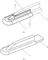
fig. 1 - shows an exemplary mold together with an insulating component in an axonometric view, -
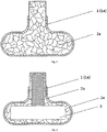
fig. 2 - shows the mold with the insulation component fromfig. 1 in a cross-section, in the first embodiment of the mold, -
fig. 3 - shows the mold from thefig. 1 in a cross-section, in the second embodiment of the mold, -
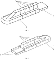
fig.4 - shows the mold fromfig. 3 with an internal core in an axonometric view, -
fig.5 - shows the mold fromfig. 4 with additional modules placed on the internal core in an axonometric view, -
fig. 6 - shows the mold fromfig. 5 having the internal core provided with longitudinal channels carried out in the core in an axonometric view, -
fig. 7 - shows the mold fromfig. 5 having the micro-pores carried out in the mold in an axonometric view, -
fig. 8 - shows the mold with the insulation component fromfig. 3 in a cross-section, having the internal core provided with longitudinal channels carried out in the core and having the micro-pores carried out in the core, -
fig. 9 - presents the flow chart of the manufacturing steps. - In the exemplary embodiment the
insulation component 1 is formed on amold 2. The component has a form of a transformer foot insulation element for a power transformer. Theinsulation component 1 has a shape projecting the shape of themold 2. The method of manufacturing of aninsulation component 1 comprises the following steps, presented infig. 9 : - Pre-preparing a
mold 2 for theinsulation component 1 according to the shape of the insulation component from non-metallic material, preferably from thermoplastic like for example polycarbonate, polyamide, polyetherimide or thermoset polymer like for example acrylic or epoxy resin and having an open-like porous structure or lattice-like structure in any form, which structure is adapted to be non-permeable for cellulosic material in the form of wet sheet made of unbleached cellulose kraft pulp, - Depositing a cellulose material in the form of wet sheet made of unbleached cellulose kraft pulp on an external surface of the
mold 2, - Modeling an
insulation component 1 by pressing the wet cellulose kraft pulp to the external surface of themold 2 in order to map the shape of themold 2 into ashell 1a of theinsulation component 1, where the modeling is performed manually by pressing the pulp to the external surface of the mold or using a classic pressing tool, not presented in the drawing, - Drying the
shell 1a of theinsulation component 1 by using external microwave sources of heat with a wavelength range of 3÷300 mm and a frequency range of 0,3÷300 GHz that heats theshell 1a of the component directly up to temperature in the range of 100÷200°C, - Removing the
shell 1 a of thecomponent 1 from themold matrix 2 by any known way, - Machining of the
dried shell 1a of theraw component 1 into the final shape of theinsulation component 1. - In the step of pre-preparing, a
mold 2 for manufacturing of aninsulation component 1 is prepared. Theinsulation component 1 has a shape projecting the shape of themold 2. An exemplary transformer foot insulation element for transformer deposited on themold 2 is presented in the drawing. The shape of the insulation component could be very complicated, so the additive manufacturing technology is used to prepare themold 2. As the insulation component is applied as an electrical insulation component, any metallic particles or even track of metal contamination can not be present in its structure. The mold is prepared from non-metallic material, for example from thermoplastic like polycarbonate, polyamide, polyetherimide or thermoset polymer like acrylic or epoxy resin. For the transformer foot insulation element the structure of the mold is made as abulky mold structure 2a, (fig. 2 ) for all cross sections of the mold or is made as a casing with abulky structure 2a of the wall of the casing, (fig. 3 ) with acavity 3 inside the mold and having a part with lattice-like structure 2b. In the cavity 3 acore 4 is inserted which is protruding outside of themold 2 to form an internal inset for at least oneadditional module 5 slid over thecore 4. The length of thecore 4 is determined by the need of the shape of thecomponent 1. For the transformer foot insulation element at least oneadditional module 5 is placed along the longitudinal axis ofcore 4 in such a way that eachadditional module 5 can change the shape of a mold and can lengthen for example the length of the mold. Such modification of the mold renders it as universal mold. - The core of the
mold 1 can have a speciallongitudinal channels 6 made inside the core structure. Themold 2 can have a system ofmicro channels 7 inside that are connected with thechannels 6 in the core of themold 2. These channels could be very useful in the step of drying the component on the mold what is explained in thestep 4. - In this step a wet pulp is deposited on the external surface of the mold. For manufacturing an insulation component a wet sheet of an unbleached
cellulose kraft pulp 7 is prepared. The sheet is superimposed on the mold manually layer by layers or the wet sheet can be superimposed by a special tool or tools, not presented in the drawing. - This step is realized by pressing the wet
cellulose kraft pulp 7 to the external surface of themold 2 in order to map the shape of themold 2 into ashell 1 a of theinsulation component 1, where the modeling is performed manually by pressing the pulp to the external surface of the mold or using a classic pressing tool, not presented in the drawing. - The step of drying the
shell 1a of theinsulation component 1 is performed by using an external microwave sources of heat with a wavelength range of 3÷300 mm and a frequency range of 0,3÷300 GHz that heats the cellulose material of theinsulation component 1 directly up to temperature in the range of 100÷200°C. In this method the heat is generated directly inside the material being dried by microwave heating and the evaporated water is transferred either outside themold 2 into environment or towards themold 2 and then is transferred through the system ofmicro-channels 7 inside themold 2 and thechannels 6 inside thecore 4 of themold 2. Additionally there can be a pump connected to thechannels 6 in the core sucking and evacuating the moistured air from the component being dried, what is not presented in the drawing. - In this step removing the
shell 1a of the component from themold 2 is carried out manually or mechanically with tools assigned for such a work. - Machining of the dried
shell 1 a of the component into the final shape of theinsulation component 1 in a known way by using band saw and by deburring the component edges on a grinding machine.
Claims (8)
- The method of manufacturing of an insulation component (1) for electric applications made of cellulosic material using a mold (2) being pre-prepared for the insulation component (1); the method having a step in which a wet sheet of cellulose pulp is deposited on the mold (2) and comprises the step of modeling a shell (1 a) of a raw insulation component (1) by pressing the wet sheet of the cellulose pulp to external surface of the mold (2) in order to map the shape of the mold (1) into a shell (1a) of the raw insulation component (1), having a step of drying the shell (1a) of the raw component (1), step of removing the shell (1a) of the raw component (1) from the mold (1) and step of machining of the dried shell (1 a) of the raw component into the final shape of the insulation component (1); characterized in that in the step of pre-preparing the mold (2), only the non-metallic material is used to form the mold (2), the mold (2) is manufactured in any additive manufacturing process and has a bulky like structure (2a) with an open-like porous structure or a lattice-like structure (2b) in any form, or structure being their combination which structure is adapted to be non-permeable for cellulosic material in the form of wet sheet made of unbleached cellulose kraft pulp during the step of forming and drying the shell (1 a) of the raw component (1), and the step of drying the shell (1 a) of the raw component (1) is performed by using an external microwave sources of heat.
- The method according to claim 1, characterized in that the microwave sources of heat have a wavelength range of 3÷300 mm and a frequency range of 0,3÷300 GHz.
- The method according to claims 1-2, characterized in that the mold (2) is made from thermoplastic like for example polycarbonate, polyamide, polyetherimide or thermoset polymer like for example acrylic or epoxy resin.
- The mold for manufacturing of an insulation component (1) for electric applications according to method presented in the claims 1-3, characterized in that the mold (2) has a bulky structure (2a) in a cross-sections made along whole length of the mold.
- The mold for manufacturing of an insulation component (1) for electric applications according to method presented in the claims 1-3, characterized in that the mold (2) is provided with a cavity (3) made along the length of the mold.
- The mold according to claim 5, characterized in that the mold (2) is equipped with an internal core (4) which is inserted to cavity (3) inside the mold (1).
- The mold according to claim 5, characterized in that the internal core (4) is protruding from the mold (2) to form an internal inset for at least one additional module (5) slid over the core (4).
- The mold according to claim 5, characterized in that the internal core (4) is equipped with at least one internal channel (6) placed longitudinal in the core (4) which is connected with a system of micro channels (7a) made inside the core (4) and micro-channels (7) made inside the mold (2) in the structure (2a) which are adapted for transferring outside the mold (2) an evaporated water from the cellulose kraft pulp.
Priority Applications (1)
| Application Number | Priority Date | Filing Date | Title |
|---|---|---|---|
| EP16460104.9A EP3342572B1 (en) | 2016-12-30 | 2016-12-30 | Method of manufacturing an insulation component for electric applications |
Applications Claiming Priority (1)
| Application Number | Priority Date | Filing Date | Title |
|---|---|---|---|
| EP16460104.9A EP3342572B1 (en) | 2016-12-30 | 2016-12-30 | Method of manufacturing an insulation component for electric applications |
Publications (2)
| Publication Number | Publication Date |
|---|---|
| EP3342572A1 true EP3342572A1 (en) | 2018-07-04 |
| EP3342572B1 EP3342572B1 (en) | 2020-12-02 |
Family
ID=57962984
Family Applications (1)
| Application Number | Title | Priority Date | Filing Date |
|---|---|---|---|
| EP16460104.9A Active EP3342572B1 (en) | 2016-12-30 | 2016-12-30 | Method of manufacturing an insulation component for electric applications |
Country Status (1)
| Country | Link |
|---|---|
| EP (1) | EP3342572B1 (en) |
Citations (6)
| Publication number | Priority date | Publication date | Assignee | Title |
|---|---|---|---|---|
| DE963438C (en) * | 1950-02-11 | 1957-05-09 | Siemens Ag | Improvement of the dielectric properties of insulating paper |
| EP0656444A1 (en) * | 1993-11-09 | 1995-06-07 | Bowater plc | Process for making pulp mouldings |
| DE19832399A1 (en) * | 1998-07-18 | 1999-01-14 | Bernd Prof Dr Ing Kuenne | Mould for fibre workpiece materials |
| GB2413301A (en) * | 2004-04-20 | 2005-10-26 | Glory Team Ind Ltd | A method of producing pulp-moulded products, a mould for use in such a method and an apparatus for incorporating such a method |
| GB2456502A (en) | 2007-11-17 | 2009-07-22 | 3T Rpd Ltd | A permeable shaping tool, a method of shaping and of handling an article |
| EP3012282A1 (en) * | 2014-10-20 | 2016-04-27 | ABB Technology Ltd | Pressboard |
-
2016
- 2016-12-30 EP EP16460104.9A patent/EP3342572B1/en active Active
Patent Citations (6)
| Publication number | Priority date | Publication date | Assignee | Title |
|---|---|---|---|---|
| DE963438C (en) * | 1950-02-11 | 1957-05-09 | Siemens Ag | Improvement of the dielectric properties of insulating paper |
| EP0656444A1 (en) * | 1993-11-09 | 1995-06-07 | Bowater plc | Process for making pulp mouldings |
| DE19832399A1 (en) * | 1998-07-18 | 1999-01-14 | Bernd Prof Dr Ing Kuenne | Mould for fibre workpiece materials |
| GB2413301A (en) * | 2004-04-20 | 2005-10-26 | Glory Team Ind Ltd | A method of producing pulp-moulded products, a mould for use in such a method and an apparatus for incorporating such a method |
| GB2456502A (en) | 2007-11-17 | 2009-07-22 | 3T Rpd Ltd | A permeable shaping tool, a method of shaping and of handling an article |
| EP3012282A1 (en) * | 2014-10-20 | 2016-04-27 | ABB Technology Ltd | Pressboard |
Non-Patent Citations (1)
| Title |
|---|
| UNKNOWN: "Molded Fiber - 3D Printing for Paper Pulp Molds", 2 May 2015 (2015-05-02), XP055353297, Retrieved from the Internet <URL:http://web.archive.org/web/20150905135428/http://www.stratasys.com/solutions/additive-manufacturing/tooling/molded-fiber> [retrieved on 20170309] * |
Also Published As
| Publication number | Publication date |
|---|---|
| EP3342572B1 (en) | 2020-12-02 |
Similar Documents
| Publication | Publication Date | Title |
|---|---|---|
| CN110983862B (en) | Tool or tool part for use in a process for moulding a product from a slurry | |
| CN101821076B (en) | Method for producing fibre-composite component | |
| KR101832991B1 (en) | Porous sintered pulp mould comprising a partially machined flat bottom surface | |
| CN105130483B (en) | Compound quartz pottery antenna covering cover body compression-molding method and its special compression mould | |
| KR101883195B1 (en) | Pulp mould comprising heating element with sintered necks | |
| JP6990664B2 (en) | Methods and equipment for casting and solidifying fiber preforms | |
| CN103878899A (en) | Process for manufacturing a textile preform with continuous fibres by circulation of hot gas flow through a fibrous array | |
| CN104071970A (en) | Curved glass moulding method and die adopted by the method | |
| JP3208329U (en) | Carbon fiber product molding equipment | |
| CN102713063A (en) | Base plate for pulp moulds | |
| KR20130132237A (en) | Cellulosic pulp mould comprising an impermeable outer surface | |
| EP2255038A1 (en) | A device and a method for compression moulding of a fibre tray | |
| CN103348062A (en) | Pulp mold device | |
| CN205000197U (en) | Microwave drying molding device for wet paper plastic process | |
| WO2015169929A3 (en) | Method for manufacturing large ceramic co-fired articles | |
| FI125953B (en) | Procedure for manufacturing an RF filter and RF filter | |
| EP3342572B1 (en) | Method of manufacturing an insulation component for electric applications | |
| JP5814481B1 (en) | Manufacturing apparatus and manufacturing method for resin molded product | |
| US20150097313A1 (en) | Method for making a molded composite article | |
| CN105690047B (en) | Method for manufacturing porous metal mold for wet paper molding process | |
| US10326341B2 (en) | Method for producing a rotor of an electric asynchronous machine | |
| JP6822831B2 (en) | Fiber reinforced thermoplastic sheet for thermoforming | |
| KR102289560B1 (en) | Oven Apparatus for Heat Treatment of Multi Layer Ceramic Capacitor | |
| JP6357010B2 (en) | Optical element molding die set and optical element manufacturing method | |
| CN203866648U (en) | Die special for combined firework die-pressing basin frame |
Legal Events
| Date | Code | Title | Description |
|---|---|---|---|
| PUAI | Public reference made under article 153(3) epc to a published international application that has entered the european phase |
Free format text: ORIGINAL CODE: 0009012 |
|
| STAA | Information on the status of an ep patent application or granted ep patent |
Free format text: STATUS: THE APPLICATION HAS BEEN PUBLISHED |
|
| AK | Designated contracting states |
Kind code of ref document: A1 Designated state(s): AL AT BE BG CH CY CZ DE DK EE ES FI FR GB GR HR HU IE IS IT LI LT LU LV MC MK MT NL NO PL PT RO RS SE SI SK SM TR |
|
| AX | Request for extension of the european patent |
Extension state: BA ME |
|
| STAA | Information on the status of an ep patent application or granted ep patent |
Free format text: STATUS: REQUEST FOR EXAMINATION WAS MADE |
|
| 17P | Request for examination filed |
Effective date: 20181214 |
|
| RBV | Designated contracting states (corrected) |
Designated state(s): AL AT BE BG CH CY CZ DE DK EE ES FI FR GB GR HR HU IE IS IT LI LT LU LV MC MK MT NL NO PL PT RO RS SE SI SK SM TR |
|
| STAA | Information on the status of an ep patent application or granted ep patent |
Free format text: STATUS: EXAMINATION IS IN PROGRESS |
|
| 17Q | First examination report despatched |
Effective date: 20190726 |
|
| GRAP | Despatch of communication of intention to grant a patent |
Free format text: ORIGINAL CODE: EPIDOSNIGR1 |
|
| STAA | Information on the status of an ep patent application or granted ep patent |
Free format text: STATUS: GRANT OF PATENT IS INTENDED |
|
| INTG | Intention to grant announced |
Effective date: 20200518 |
|
| RAP1 | Party data changed (applicant data changed or rights of an application transferred) |
Owner name: ABB SCHWEIZ AG |
|
| RAP1 | Party data changed (applicant data changed or rights of an application transferred) |
Owner name: ABB POWER GRIDS SWITZERLAND AG |
|
| GRAJ | Information related to disapproval of communication of intention to grant by the applicant or resumption of examination proceedings by the epo deleted |
Free format text: ORIGINAL CODE: EPIDOSDIGR1 |
|
| STAA | Information on the status of an ep patent application or granted ep patent |
Free format text: STATUS: EXAMINATION IS IN PROGRESS |
|
| INTC | Intention to grant announced (deleted) | ||
| GRAR | Information related to intention to grant a patent recorded |
Free format text: ORIGINAL CODE: EPIDOSNIGR71 |
|
| GRAS | Grant fee paid |
Free format text: ORIGINAL CODE: EPIDOSNIGR3 |
|
| STAA | Information on the status of an ep patent application or granted ep patent |
Free format text: STATUS: GRANT OF PATENT IS INTENDED |
|
| GRAA | (expected) grant |
Free format text: ORIGINAL CODE: 0009210 |
|
| STAA | Information on the status of an ep patent application or granted ep patent |
Free format text: STATUS: THE PATENT HAS BEEN GRANTED |
|
| AK | Designated contracting states |
Kind code of ref document: B1 Designated state(s): AL AT BE BG CH CY CZ DE DK EE ES FI FR GB GR HR HU IE IS IT LI LT LU LV MC MK MT NL NO PL PT RO RS SE SI SK SM TR |
|
| INTG | Intention to grant announced |
Effective date: 20201028 |
|
| REG | Reference to a national code |
Ref country code: GB Ref legal event code: FG4D |
|
| REG | Reference to a national code |
Ref country code: AT Ref legal event code: REF Ref document number: 1340410 Country of ref document: AT Kind code of ref document: T Effective date: 20201215 Ref country code: CH Ref legal event code: EP |
|
| REG | Reference to a national code |
Ref country code: IE Ref legal event code: FG4D |
|
| REG | Reference to a national code |
Ref country code: DE Ref legal event code: R096 Ref document number: 602016048962 Country of ref document: DE |
|
| PG25 | Lapsed in a contracting state [announced via postgrant information from national office to epo] |
Ref country code: GR Free format text: LAPSE BECAUSE OF FAILURE TO SUBMIT A TRANSLATION OF THE DESCRIPTION OR TO PAY THE FEE WITHIN THE PRESCRIBED TIME-LIMIT Effective date: 20210303 Ref country code: FI Free format text: LAPSE BECAUSE OF FAILURE TO SUBMIT A TRANSLATION OF THE DESCRIPTION OR TO PAY THE FEE WITHIN THE PRESCRIBED TIME-LIMIT Effective date: 20201202 Ref country code: NO Free format text: LAPSE BECAUSE OF FAILURE TO SUBMIT A TRANSLATION OF THE DESCRIPTION OR TO PAY THE FEE WITHIN THE PRESCRIBED TIME-LIMIT Effective date: 20210302 Ref country code: RS Free format text: LAPSE BECAUSE OF FAILURE TO SUBMIT A TRANSLATION OF THE DESCRIPTION OR TO PAY THE FEE WITHIN THE PRESCRIBED TIME-LIMIT Effective date: 20201202 |
|
| REG | Reference to a national code |
Ref country code: NL Ref legal event code: MP Effective date: 20201202 |
|
| REG | Reference to a national code |
Ref country code: AT Ref legal event code: MK05 Ref document number: 1340410 Country of ref document: AT Kind code of ref document: T Effective date: 20201202 |
|
| PG25 | Lapsed in a contracting state [announced via postgrant information from national office to epo] |
Ref country code: SE Free format text: LAPSE BECAUSE OF FAILURE TO SUBMIT A TRANSLATION OF THE DESCRIPTION OR TO PAY THE FEE WITHIN THE PRESCRIBED TIME-LIMIT Effective date: 20201202 Ref country code: BG Free format text: LAPSE BECAUSE OF FAILURE TO SUBMIT A TRANSLATION OF THE DESCRIPTION OR TO PAY THE FEE WITHIN THE PRESCRIBED TIME-LIMIT Effective date: 20210302 Ref country code: LV Free format text: LAPSE BECAUSE OF FAILURE TO SUBMIT A TRANSLATION OF THE DESCRIPTION OR TO PAY THE FEE WITHIN THE PRESCRIBED TIME-LIMIT Effective date: 20201202 Ref country code: PL Free format text: LAPSE BECAUSE OF FAILURE TO SUBMIT A TRANSLATION OF THE DESCRIPTION OR TO PAY THE FEE WITHIN THE PRESCRIBED TIME-LIMIT Effective date: 20201202 |
|
| PG25 | Lapsed in a contracting state [announced via postgrant information from national office to epo] |
Ref country code: NL Free format text: LAPSE BECAUSE OF FAILURE TO SUBMIT A TRANSLATION OF THE DESCRIPTION OR TO PAY THE FEE WITHIN THE PRESCRIBED TIME-LIMIT Effective date: 20201202 Ref country code: HR Free format text: LAPSE BECAUSE OF FAILURE TO SUBMIT A TRANSLATION OF THE DESCRIPTION OR TO PAY THE FEE WITHIN THE PRESCRIBED TIME-LIMIT Effective date: 20201202 |
|
| REG | Reference to a national code |
Ref country code: LT Ref legal event code: MG9D |
|
| PG25 | Lapsed in a contracting state [announced via postgrant information from national office to epo] |
Ref country code: SK Free format text: LAPSE BECAUSE OF FAILURE TO SUBMIT A TRANSLATION OF THE DESCRIPTION OR TO PAY THE FEE WITHIN THE PRESCRIBED TIME-LIMIT Effective date: 20201202 Ref country code: RO Free format text: LAPSE BECAUSE OF FAILURE TO SUBMIT A TRANSLATION OF THE DESCRIPTION OR TO PAY THE FEE WITHIN THE PRESCRIBED TIME-LIMIT Effective date: 20201202 Ref country code: PT Free format text: LAPSE BECAUSE OF FAILURE TO SUBMIT A TRANSLATION OF THE DESCRIPTION OR TO PAY THE FEE WITHIN THE PRESCRIBED TIME-LIMIT Effective date: 20210405 Ref country code: SM Free format text: LAPSE BECAUSE OF FAILURE TO SUBMIT A TRANSLATION OF THE DESCRIPTION OR TO PAY THE FEE WITHIN THE PRESCRIBED TIME-LIMIT Effective date: 20201202 Ref country code: LT Free format text: LAPSE BECAUSE OF FAILURE TO SUBMIT A TRANSLATION OF THE DESCRIPTION OR TO PAY THE FEE WITHIN THE PRESCRIBED TIME-LIMIT Effective date: 20201202 Ref country code: EE Free format text: LAPSE BECAUSE OF FAILURE TO SUBMIT A TRANSLATION OF THE DESCRIPTION OR TO PAY THE FEE WITHIN THE PRESCRIBED TIME-LIMIT Effective date: 20201202 Ref country code: CZ Free format text: LAPSE BECAUSE OF FAILURE TO SUBMIT A TRANSLATION OF THE DESCRIPTION OR TO PAY THE FEE WITHIN THE PRESCRIBED TIME-LIMIT Effective date: 20201202 |
|
| PG25 | Lapsed in a contracting state [announced via postgrant information from national office to epo] |
Ref country code: AT Free format text: LAPSE BECAUSE OF FAILURE TO SUBMIT A TRANSLATION OF THE DESCRIPTION OR TO PAY THE FEE WITHIN THE PRESCRIBED TIME-LIMIT Effective date: 20201202 |
|
| REG | Reference to a national code |
Ref country code: DE Ref legal event code: R097 Ref document number: 602016048962 Country of ref document: DE Ref country code: BE Ref legal event code: MM Effective date: 20201231 |
|
| PG25 | Lapsed in a contracting state [announced via postgrant information from national office to epo] |
Ref country code: IS Free format text: LAPSE BECAUSE OF FAILURE TO SUBMIT A TRANSLATION OF THE DESCRIPTION OR TO PAY THE FEE WITHIN THE PRESCRIBED TIME-LIMIT Effective date: 20210402 Ref country code: MC Free format text: LAPSE BECAUSE OF FAILURE TO SUBMIT A TRANSLATION OF THE DESCRIPTION OR TO PAY THE FEE WITHIN THE PRESCRIBED TIME-LIMIT Effective date: 20201202 |
|
| PLBE | No opposition filed within time limit |
Free format text: ORIGINAL CODE: 0009261 |
|
| STAA | Information on the status of an ep patent application or granted ep patent |
Free format text: STATUS: NO OPPOSITION FILED WITHIN TIME LIMIT |
|
| PG25 | Lapsed in a contracting state [announced via postgrant information from national office to epo] |
Ref country code: LU Free format text: LAPSE BECAUSE OF NON-PAYMENT OF DUE FEES Effective date: 20201230 Ref country code: FR Free format text: LAPSE BECAUSE OF NON-PAYMENT OF DUE FEES Effective date: 20210202 Ref country code: IT Free format text: LAPSE BECAUSE OF FAILURE TO SUBMIT A TRANSLATION OF THE DESCRIPTION OR TO PAY THE FEE WITHIN THE PRESCRIBED TIME-LIMIT Effective date: 20201202 Ref country code: IE Free format text: LAPSE BECAUSE OF NON-PAYMENT OF DUE FEES Effective date: 20201230 Ref country code: AL Free format text: LAPSE BECAUSE OF FAILURE TO SUBMIT A TRANSLATION OF THE DESCRIPTION OR TO PAY THE FEE WITHIN THE PRESCRIBED TIME-LIMIT Effective date: 20201202 |
|
| 26N | No opposition filed |
Effective date: 20210903 |
|
| GBPC | Gb: european patent ceased through non-payment of renewal fee |
Effective date: 20210302 |
|
| PG25 | Lapsed in a contracting state [announced via postgrant information from national office to epo] |
Ref country code: DK Free format text: LAPSE BECAUSE OF FAILURE TO SUBMIT A TRANSLATION OF THE DESCRIPTION OR TO PAY THE FEE WITHIN THE PRESCRIBED TIME-LIMIT Effective date: 20201202 Ref country code: SI Free format text: LAPSE BECAUSE OF FAILURE TO SUBMIT A TRANSLATION OF THE DESCRIPTION OR TO PAY THE FEE WITHIN THE PRESCRIBED TIME-LIMIT Effective date: 20201202 |
|
| PG25 | Lapsed in a contracting state [announced via postgrant information from national office to epo] |
Ref country code: GB Free format text: LAPSE BECAUSE OF NON-PAYMENT OF DUE FEES Effective date: 20210302 Ref country code: ES Free format text: LAPSE BECAUSE OF FAILURE TO SUBMIT A TRANSLATION OF THE DESCRIPTION OR TO PAY THE FEE WITHIN THE PRESCRIBED TIME-LIMIT Effective date: 20201202 |
|
| PG25 | Lapsed in a contracting state [announced via postgrant information from national office to epo] |
Ref country code: IS Free format text: LAPSE BECAUSE OF FAILURE TO SUBMIT A TRANSLATION OF THE DESCRIPTION OR TO PAY THE FEE WITHIN THE PRESCRIBED TIME-LIMIT Effective date: 20210402 Ref country code: TR Free format text: LAPSE BECAUSE OF FAILURE TO SUBMIT A TRANSLATION OF THE DESCRIPTION OR TO PAY THE FEE WITHIN THE PRESCRIBED TIME-LIMIT Effective date: 20201202 Ref country code: MT Free format text: LAPSE BECAUSE OF FAILURE TO SUBMIT A TRANSLATION OF THE DESCRIPTION OR TO PAY THE FEE WITHIN THE PRESCRIBED TIME-LIMIT Effective date: 20201202 Ref country code: CY Free format text: LAPSE BECAUSE OF FAILURE TO SUBMIT A TRANSLATION OF THE DESCRIPTION OR TO PAY THE FEE WITHIN THE PRESCRIBED TIME-LIMIT Effective date: 20201202 |
|
| REG | Reference to a national code |
Ref country code: DE Ref legal event code: R081 Ref document number: 602016048962 Country of ref document: DE Owner name: HITACHI ENERGY SWITZERLAND AG, CH Free format text: FORMER OWNER: ABB POWER GRIDS SWITZERLAND AG, BADEN, CH Ref country code: DE Ref legal event code: R081 Ref document number: 602016048962 Country of ref document: DE Owner name: HITACHI ENERGY LTD, CH Free format text: FORMER OWNER: ABB POWER GRIDS SWITZERLAND AG, BADEN, CH |
|
| PG25 | Lapsed in a contracting state [announced via postgrant information from national office to epo] |
Ref country code: MK Free format text: LAPSE BECAUSE OF FAILURE TO SUBMIT A TRANSLATION OF THE DESCRIPTION OR TO PAY THE FEE WITHIN THE PRESCRIBED TIME-LIMIT Effective date: 20201202 |
|
| PG25 | Lapsed in a contracting state [announced via postgrant information from national office to epo] |
Ref country code: BE Free format text: LAPSE BECAUSE OF NON-PAYMENT OF DUE FEES Effective date: 20201231 |
|
| P01 | Opt-out of the competence of the unified patent court (upc) registered |
Effective date: 20230527 |
|
| REG | Reference to a national code |
Ref country code: DE Ref legal event code: R082 Ref document number: 602016048962 Country of ref document: DE Representative=s name: DENNEMEYER & ASSOCIATES RECHTSANWALTSGESELLSCH, DE Ref country code: DE Ref legal event code: R082 Ref document number: 602016048962 Country of ref document: DE Representative=s name: DENNEMEYER & ASSOCIATES S.A., DE Ref country code: DE Ref legal event code: R081 Ref document number: 602016048962 Country of ref document: DE Owner name: HITACHI ENERGY LTD, CH Free format text: FORMER OWNER: HITACHI ENERGY SWITZERLAND AG, BADEN, CH |
|
| REG | Reference to a national code |
Ref country code: DE Ref legal event code: R082 Ref document number: 602016048962 Country of ref document: DE Representative=s name: DENNEMEYER & ASSOCIATES RECHTSANWALTSGESELLSCH, DE |
|
| REG | Reference to a national code |
Ref country code: CH Ref legal event code: U11 Free format text: ST27 STATUS EVENT CODE: U-0-0-U10-U11 (AS PROVIDED BY THE NATIONAL OFFICE) Effective date: 20260101 |
|
| PGFP | Annual fee paid to national office [announced via postgrant information from national office to epo] |
Ref country code: DE Payment date: 20251211 Year of fee payment: 10 |
|
| PGFP | Annual fee paid to national office [announced via postgrant information from national office to epo] |
Ref country code: CH Payment date: 20260101 Year of fee payment: 10 |