EP3342350A2 - System and method for breast imaging - Google Patents
System and method for breast imaging Download PDFInfo
- Publication number
- EP3342350A2 EP3342350A2 EP17209477.3A EP17209477A EP3342350A2 EP 3342350 A2 EP3342350 A2 EP 3342350A2 EP 17209477 A EP17209477 A EP 17209477A EP 3342350 A2 EP3342350 A2 EP 3342350A2
- Authority
- EP
- European Patent Office
- Prior art keywords
- ultrasound
- compression paddle
- ray
- compression
- ultrasound probe
- Prior art date
- Legal status (The legal status is an assumption and is not a legal conclusion. Google has not performed a legal analysis and makes no representation as to the accuracy of the status listed.)
- Granted
Links
Images






Classifications
-
- A—HUMAN NECESSITIES
- A61—MEDICAL OR VETERINARY SCIENCE; HYGIENE
- A61B—DIAGNOSIS; SURGERY; IDENTIFICATION
- A61B6/00—Apparatus or devices for radiation diagnosis; Apparatus or devices for radiation diagnosis combined with radiation therapy equipment
- A61B6/02—Arrangements for diagnosis sequentially in different planes; Stereoscopic radiation diagnosis
- A61B6/025—Tomosynthesis
-
- A—HUMAN NECESSITIES
- A61—MEDICAL OR VETERINARY SCIENCE; HYGIENE
- A61B—DIAGNOSIS; SURGERY; IDENTIFICATION
- A61B6/00—Apparatus or devices for radiation diagnosis; Apparatus or devices for radiation diagnosis combined with radiation therapy equipment
- A61B6/50—Apparatus or devices for radiation diagnosis; Apparatus or devices for radiation diagnosis combined with radiation therapy equipment specially adapted for specific body parts; specially adapted for specific clinical applications
- A61B6/502—Apparatus or devices for radiation diagnosis; Apparatus or devices for radiation diagnosis combined with radiation therapy equipment specially adapted for specific body parts; specially adapted for specific clinical applications for diagnosis of breast, i.e. mammography
-
- A—HUMAN NECESSITIES
- A61—MEDICAL OR VETERINARY SCIENCE; HYGIENE
- A61B—DIAGNOSIS; SURGERY; IDENTIFICATION
- A61B6/00—Apparatus or devices for radiation diagnosis; Apparatus or devices for radiation diagnosis combined with radiation therapy equipment
- A61B6/04—Positioning of patients; Tiltable beds or the like
- A61B6/0407—Supports, e.g. tables or beds, for the body or parts of the body
- A61B6/0414—Supports, e.g. tables or beds, for the body or parts of the body with compression means
-
- A—HUMAN NECESSITIES
- A61—MEDICAL OR VETERINARY SCIENCE; HYGIENE
- A61B—DIAGNOSIS; SURGERY; IDENTIFICATION
- A61B6/00—Apparatus or devices for radiation diagnosis; Apparatus or devices for radiation diagnosis combined with radiation therapy equipment
- A61B6/44—Constructional features of apparatus for radiation diagnosis
- A61B6/4417—Constructional features of apparatus for radiation diagnosis related to combined acquisition of different diagnostic modalities
-
- A—HUMAN NECESSITIES
- A61—MEDICAL OR VETERINARY SCIENCE; HYGIENE
- A61B—DIAGNOSIS; SURGERY; IDENTIFICATION
- A61B6/00—Apparatus or devices for radiation diagnosis; Apparatus or devices for radiation diagnosis combined with radiation therapy equipment
- A61B6/44—Constructional features of apparatus for radiation diagnosis
- A61B6/4429—Constructional features of apparatus for radiation diagnosis related to the mounting of source units and detector units
- A61B6/4435—Constructional features of apparatus for radiation diagnosis related to the mounting of source units and detector units the source unit and the detector unit being coupled by a rigid structure
-
- A—HUMAN NECESSITIES
- A61—MEDICAL OR VETERINARY SCIENCE; HYGIENE
- A61B—DIAGNOSIS; SURGERY; IDENTIFICATION
- A61B8/00—Diagnosis using ultrasonic, sonic or infrasonic waves
- A61B8/08—Clinical applications
- A61B8/0825—Clinical applications for diagnosis of the breast, e.g. mammography
-
- A—HUMAN NECESSITIES
- A61—MEDICAL OR VETERINARY SCIENCE; HYGIENE
- A61B—DIAGNOSIS; SURGERY; IDENTIFICATION
- A61B8/00—Diagnosis using ultrasonic, sonic or infrasonic waves
- A61B8/40—Positioning of patients, e.g. means for holding or immobilising parts of the patient's body
- A61B8/403—Positioning of patients, e.g. means for holding or immobilising parts of the patient's body using compression means
-
- A—HUMAN NECESSITIES
- A61—MEDICAL OR VETERINARY SCIENCE; HYGIENE
- A61B—DIAGNOSIS; SURGERY; IDENTIFICATION
- A61B8/00—Diagnosis using ultrasonic, sonic or infrasonic waves
- A61B8/44—Constructional features of the ultrasonic, sonic or infrasonic diagnostic device
- A61B8/4416—Constructional features of the ultrasonic, sonic or infrasonic diagnostic device related to combined acquisition of different diagnostic modalities, e.g. combination of ultrasound and X-ray acquisitions
-
- A—HUMAN NECESSITIES
- A61—MEDICAL OR VETERINARY SCIENCE; HYGIENE
- A61B—DIAGNOSIS; SURGERY; IDENTIFICATION
- A61B6/00—Apparatus or devices for radiation diagnosis; Apparatus or devices for radiation diagnosis combined with radiation therapy equipment
- A61B6/54—Control of apparatus or devices for radiation diagnosis
- A61B6/547—Control of apparatus or devices for radiation diagnosis involving tracking of position of the device or parts of the device
Definitions
- the field of the disclosure relates generally to breast imaging systems, and, more particularly, to breast imaging systems including ultrasound and x-ray using a dual-sided compression paddle system and the methods of operation for acquiring breast images.
- Breast cancer screening is performed with x-ray imaging in either two-dimensional, i.e., mammography, and in recent years, tomosynthesis (three-dimensional x-ray). For many women, such x-ray screening is sufficient for generating images that are satisfactory for review by a medical professional. However, many women have a high percentage of dense breast tissues which do not show contrast versus cancerous tissues and additional screening is performed through ultrasound imaging. Ultrasound imaging is often performed in a supine position whereas the x-ray mammography is performed with the women upright with the breast in a compressed position. Such shifting of position of the patient shifts the shape and the tissue of the breast making any registration of the two imaging modalities difficult.
- the ultrasound probe To perform ultrasound imaging, the ultrasound probe must be in contact with the tissue or a coupling medium such as ultrasound gel or lotion or water. However, if the ultrasound gel is applied to the breast prior to taking the x-ray image it may result in artifacts in the x-ray image.
- the ultrasound attenuation issue described above remains and additionally coupling medium for the ultrasound probe absorbs a significant portion of the x-rays after exposing the patient. This results in necessitating a higher x-ray dose to the patient. Furthermore the distance between the x-ray detector and the patient is increased. This may result in degradation of the x-ray image quality as well.
- Dual sided scanning with ultrasound on a separate system in the mammography configuration has also been demonstrated.
- the ultrasound image quality has been preserved.
- the workflow and image registration have proven difficult, since movement of the breast being imaged is likely.
- one solution is to include features that move the x-ray detector out of the way such that the ultrasound probe can be moved into position once x-ray imaging has been performed.
- the detector is attached x-ray system gantry and does not move. For these systems an ultrasound only add-on is highly desirable.
- an imaging assembly in one aspect according to the present invention, includes a gantry and a compression system configured to receive and compress an object to be imaged.
- the compression system includes a first compression paddle coupled to the gantry and a second compression paddle coupled to the gantry.
- the imaging assembly also includes an x-ray detection device coupled to the gantry. The X-ray detection device is proximate the second compression paddle.
- the imaging assembly further includes an ultrasound system including a first ultrasound probe coupled to the first compression paddle. The first ultrasound probe is coupled to the first compression paddle. The first ultrasound probe is configured to acquire a first portion of the ultrasound image information of the object to be imaged.
- the ultrasound system also includes a second ultrasound probe coupled to the second compression paddle. The second ultrasound probe is configured to acquire a second portion of the ultrasound image information of the object to be imaged.
- a retrofit upgrade package for an installed legacy imaging system.
- the retrofit upgrade package includes a compression system configured to receive and compress an object to be imaged.
- the compression system includes a first compression paddle configured to be coupled to a gantry and a second compression paddle configured to be coupled to the gantry.
- the retrofit upgrade package also includes an ultrasound system including a first ultrasound probe coupled to the first compression paddle. The first ultrasound probe is coupled to the first compression paddle. The first ultrasound probe is configured to acquire a first portion of ultrasound image information of the object to be imaged.
- the ultrasound system also includes a second ultrasound probe coupled to the second compression paddle. The second ultrasound probe is configured to acquire a second portion of the ultrasound image information of the object to be imaged.
- a method of imaging an object includes positioning a first compression paddle to receive an object to be imaged and positioning a second compression paddle to extend over at least a portion of an x-ray detector. The method also includes positioning the object to be imaged between the first compression paddle and the second compression paddle. The method further includes generating x-ray image data of the object to be imaged. The method also includes translating the first compression paddle and the second compression paddle substantially synchronously with the object to be imaged remaining therebetween. The method further includes moving a first ultrasound probe across the first compression paddle and moving a second ultrasound probe across the second compression paddle substantially simultaneously.
- Approximating language may be applied to modify any quantitative representation that could permissibly vary without resulting in a change in the basic function to which it is related. Accordingly, a value modified by a term or terms, such as “about”, “approximately”, and “substantially”, are not to be limited to the precise value specified. In at least some instances, the approximating language may correspond to the precision of an instrument for measuring the value.
- range limitations may be combined and/or interchanged, such ranges are identified and include all the sub-ranges contained therein unless context or language indicates otherwise.
- processor and “computer,” and related terms, e.g., “processing device,” “computing device,” and “controller” are not limited to just those integrated circuits referred to in the art as a computer, but broadly refers to a microcontroller, a microcomputer, a programmable logic controller (PLC), and application specific integrated circuit, and other programmable circuits, and these terms are used interchangeably herein.
- memory may include, but it not limited to, a computer-readable medium, such as a random access memory (RAM), a computer-readable non-volatile medium, such as a flash memory.
- additional input channels may be, but are not limited to, computer peripherals associated with an operator interface such as a mouse and a keyboard.
- computer peripherals may also be used that may include, for example, but not be limited to, a scanner.
- additional output channels may include, but not be limited to, an operator interface monitor.
- the terms "software” and “firmware” are interchangeable, and include any computer program storage in memory for execution by personal computers, workstations, clients, and servers.
- non-transitory computer-readable media is intended to be representative of any tangible computer-based device implemented in any method of technology for short-term and long-term storage of information, such as, computer-readable instructions, data structures, program modules and sub-modules, or other data in any device. Therefore, the methods described herein may be encoded as executable instructions embodied in a tangible, non-transitory, computer-readable medium, including, without limitation, a storage device and/or a memory device. Such instructions, when executed by a processor, cause the processor to perform at least a portion of the methods described herein.
- non-transitory computer-readable media includes all tangible, computer-readable media, including, without limitation, non-transitory computer storage devices, including without limitation, volatile and non-volatile media, and removable and non-removable media such as firmware, physical and virtual storage, CD-ROMS, DVDs, and any other digital source such as a network or the Internet, as well as yet to be developed digital means, with the sole exception being transitory, propagating signal.
- the term "real-time” refers to at least one of the time of occurrence of the associated events, the time of measurement and collection of predetermined data, the time to process the data, and the time of a system response to the events and the environment. In the embodiments described herein, these activities and events occur substantially instantaneously.
- the terms “mammography”, sometimes used to refer to a two-dimensional x-ray system, and “tomography”, sometimes used to refer to a three-dimensional x-ray system, are used interchangeably.
- the term “mammography” is used herein to generally refer to x-ray-based imaging systems, and, if necessary to differentiate the two systems, the term tomography, or a variant thereof, will be used.
- the embodiments of the breast imaging systems described herein overcome many of the deficiencies of known x-ray and ultrasound imaging systems.
- the breast imaging systems described herein include enhancements to existing x-ray systems to include features that facilitate significant reductions in the shifting of the breast being imaged between the x-ray imaging and ultrasound imaging.
- the breast imaging systems described herein integrate x-ray imaging and ultrasound imaging on the same machine with substantially the same compression induced on the breast being imaged and substantially similar positions for both images.
- the breast imaging systems described herein are configured such that the detector is movable separate from the compression system such that the compression system and gantry may be moved in a synchronized fashion where the detector is lowered and the patient remains in compression and does not move significantly.
- the compression system couples to the mammography gantry as an attachment to the compression arm such that the compression system operates separately or in conjunction with the existing mammography compression system.
- the embodiments described herein use two ultrasound probes and scan from the top of the breast and the bottom of the breast. Such dual-sided ultrasound scanning without interfering with the x-ray imaging detector is facilitated with a mechanism to move the breast upward with the upper and lower ultrasound transducers without hurting the woman while she is compressed.
- the x-ray detector is moved downward more than 1 centimeter (cm) but less than 10 cm after the x-ray examination to facilitate providing room for the ultrasound transducer. Therefore, the breast can be as close as possible to the x-ray detector and by placing the x-ray detectors as close to the breast as possible, the quality of x-ray images is not degraded from a non-coupled examination.
- the gantry including the x-ray detector, is moved downward slightly and the two compression paddles move together such that the net effect on the breast is as small as possible.
- the two compression paddles are composed in part of a mesh material that contacts the breast to support it and apply compression and tissue immobilization.
- small bladders are integrated into the compression paddles such that when the x-ray image is complete, the gantry moves, the paddles move and the little bladder in each paddle fills with ultrasound gel, water, or other ultrasound conductive material such that good contact with the breast for the ultrasound is facilitated.
- the systems described herein are compatible with existing mammography systems and may be installed as a retrofit upgrade without modification to the legacy x-ray system.
- an add-on compression device may be used.
- This compression device will replace, or in some cases, work in conjunction with the existing compression system.
- the retrofit device attaches to the x-ray gantry as an attachment to the x-ray detector image receptor mechanism, preferably.
- the retrofit system consists of a compression device which includes one or two motors to drive two compression paddles independently. The compression paddles are such that the bottom compression paddle rests on the x-ray image receptor during x-ray imaging and is moved in conjunction with the top compression paddle before ultrasound imaging to allow room for the ultrasound transducer to move into contact with the breast.
- the compression paddles are controlled by a controller which also is in communication with the x-ray gantry or a patient lift device.
- the controller controls the movement of the compression paddles and gantry of the lift device such that the speed and distance movement of the compression paddles is parallel to that of the movement of the gantry or patient lift device.
- FIG. 1 is a perspective schematic view of a known breast imaging assembly 50.
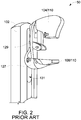
- FIG. 2 is a another perspective schematic view of known breast imaging assembly 50.
- Known breast imaging system 50 includes a known combined compression system/ultrasound assembly 60 that includes a known combined compression paddle/ultrasound probe 65 (both only shown in FIG. 1 ).
- Breast imaging assembly 50 includes a gantry 102 and an x-ray source 104 coupled to gantry 102.
- Breast imaging assembly 50 further includes an x-ray detection device 108 that is aligned with x-ray source 104, where x-ray source 104, x-ray detection device 108, and gantry 102 define a mammography system 110.
- Breast imaging assembly 50 also includes a gantry translation cradle 127, a pair of cable conduits 129 coupling detector 108 to x-ray source 104, and a gantry translation slot 131 defined within gantry 102 that receives gantry translation cradle 127.
- Both combined compression/ultrasound assembly 60 and x-ray detection device 108 are coupled to gantry translation cradle 127, and assembly 60 and detector device 108 translate up and down with cradle 127 through slot 131 as necessary to adjust to a patient as a function of the patient's height and other anatomical features.
- FIG. 3 is a front schematic perspective view of an exemplary breast imaging assembly 100.
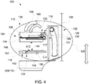
- FIG. 4 is a side schematic view of breast imaging assembly 100.
- Breast imaging assembly 100 includes gantry 102 and x-ray source 104 coupled to gantry 102, where is some embodiments, x-ray source 104 is substantially stationary, and in other embodiments, x-ray source 104 rotates upon an axis (not shown) to facilitate tomosynthesis imaging.
- Breast imaging assembly 100 further includes x-ray detection device 108 that is aligned with x-ray source 104, where x-ray source 104, x-ray detection device 108, and gantry 102 define mammography system 110.
- breast imaging assembly 100 includes a compression system 112 configured to receive and compress an object to be imaged, e.g., and without limitation, a woman's breast.
- Compression system 112 includes a first, i.e., upper compression paddle 114 translatably coupled to gantry 102 through a gantry mounting plate 116, and a translation back plate 120.
- Compression system 112 also includes a plurality of paddle positioning motors (not shown) positioned within gantry 102 and motor control features to facilitate precise positioning of paddles 114 and 118 (the motors and motor control are discussed further below).
- a paddle sliding engagement device 117 facilitates coupling paddle 114 to gantry mounting plate 116.
- Compression system 112 also includes a second, i.e., lower compression paddle 118 translatably coupled to gantry 102 though translation back plate 120.
- translation back plate 120 facilitates vertical translation of lower compression paddle 118 and upper compression paddle 114 as indicated by bi-directional translation arrow 121.
- Lower compression paddle 118 and x-ray detection device 108 are positioned proximate each other and lower compression paddle 118 rests on top of x-ray detection device 108 when breast imaging assembly 100 is in a mammography configuration (not shown in FIGs. 3 and 4 ) in contrast to an ultrasound configuration (as shown in FIGs. 3 and 4 ), where both configurations are discussed further below.
- breast imaging assembly 100 includes an ultrasound probe sub-system 122.
- compression system 112 and ultrasound probe-sub system 122 are integrated to define a combined compression/ultrasound assembly 125.
- Ultrasound probe sub-system 122 includes a first, i.e., upper ultrasound assembly 124 that includes a first, i.e., an upper probe track 128 to which upper ultrasound probe 126 is slidingly engaged, i.e., movably mounted on such that it can be moved across the top of paddle 114.
- Upper ultrasound probe 126 includes motion control features and devices (not shown) that facilitate moving probe 126 along upper probe track 128 in the directions indicated by bi-directional arrow 130.
- Upper ultrasound probe 126 is configured to acquire a first portion of the ultrasound image information of the object to be imaged.
- breast imaging assembly 100 includes gantry translation cradle 127 (shown in FIGs. 1 and 2 ), cable conduits 129 (shown in FIGs. 1 and 2 ) coupling detector 108 to x-ray source 104, and gantry translation slot 131 (shown in FIGs. 1 and 2 ) defined within gantry 102 that receives gantry translation cradle 127.
- Both combined compression/ultrasound assembly 125 and x-ray detection device 108 are coupled to gantry translation cradle 127, and assembly 125 and detector device 108 translate up and down with cradle 127 through slot 131 as necessary to adjust to a patient as a function of the patient's height and other anatomical features.
- combined compression/ultrasound assembly 125 is configured to replace combined compression system/ultrasound assembly 60 (shown in FIG. 1 ) within gantry translation cradle 127 and combined compression/ultrasound assembly 125 is compatible with known x-ray detection device 108, also configured to reside in gantry translation cradle 127.
- combined compression/ultrasound assembly 125 is configured to facilitate retrofit upgrades to known breast imaging assembly 50 (shown in FIG. 1 ) and other known breast imaging assemblies and combined compression/ultrasound assembly 125 may be installed on legacy breast imaging assemblies as at least a portion of a retrofit upgrade package.
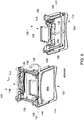
- FIG. 5 is a schematic perspective view of upper ultrasound assembly 124 in a mammography configuration 132 (not shown in FIGs. 3 and 4 ) and an ultrasound configuration 134 (also, as shown in FIGs. 3 and 4 ).
- Upper ultrasound assembly 124 includes a pivot mechanism 136 that pivotably mounts upper ultrasound assembly 124 to upper compression paddle 114.
- Upper ultrasound assembly 124 is configured to be positioned between x-ray source 104 and x-ray detector 108 (both shown in FIGs.
- upper ultrasound assembly 124 is configured to pivot, i.e., flip from a first position, i.e., ultrasound configuration 134 extending over at least a portion of upper compression paddle 114 to a second position, i.e., mammography configuration 132 proximate gantry 102.
- Arrow 138 indicates this pivoting movement.
- upper ultrasound probe 126 is substantially removed from an x-ray beam (not shown) emanated from x-ray source 104 toward x-ray detection device 108 such that upper ultrasound probe 126 does not interfere with tomographic imaging of the object being imaged.
- Upper ultrasound assembly 124 is also configured to pivot from mammography configuration 132 to ultrasound configuration 134 to facilitate acquisition of the first portion of the ultrasound image information of the object to be imaged.
- Arrow 140 indicates this pivoting movement.
- Upper ultrasound assembly 124 has a lateral length L UA and upper ultrasound probe 126 has a lateral length L UP .
- Lateral length L UA and lateral length L UP have any values that enable operation of breast imaging assembly 100 as described herein.
- lateral length L UA is approximately 30 centimeters (cm) from the left track 128 to the right track 128 and lateral length L UP is approximately 15 cm.
- upper ultrasound probe 126 moves in a centered configuration along tracks 128 through upper ultrasound probe 126.
- lateral length L UP is not long enough to cover an entire breast (not shown in FIG. 5 ) laterally, then a second sweep may be performed.
- lateral length L UP is approximately 30 cm to facilitate more rapid scanning and seamless integration of the two sweeps of the probe. This concept can be used in single side or even supine imaging system.
- sweeps of probe 126 are lateral, i.e., from side to side.
- Such embodiments will require reconfiguration of upper ultrasound assembly 124, e.g., tracks 128 and ultrasound probe 126 rotated 90 degrees to facilitate lateral, i.e., left-to-right scans rather than those front-to-back scans performed by the exemplary embodiment.
- upper ultrasound assembly 124 e.g., tracks 128 and ultrasound probe 126 rotated 90 degrees to facilitate lateral, i.e., left-to-right scans rather than those front-to-back scans performed by the exemplary embodiment.
- the sweep is performed side to side, only one sweep will be needed for reason including, and without limitation, substantially asymmetric compression, breast size, and breast tissue density.
- ultrasound probe sub-system 122 includes a second, i.e., lower ultrasound assembly 142 that includes a second, i.e., a lower probe track 144 to which a lower ultrasound probe 146 is slidingly engaged, i.e., movably mounted on.
- lower ultrasound assembly 142 is removably coupled to lower compression paddle 118 such that lower ultrasound assembly 142 is easily and quickly installed and removed from lower compression paddle 118 for those embodiments that may require some assembly and disassembly between x-ray and ultrasound imaging.
- Lower ultrasound probe 146 includes motion control features and devices (not shown) that facilitate moving probe 146 along lower probe track 144 in the directions indicated by bi-directional arrow 148.
- lower ultrasound assembly 142 and lower ultrasound probe 146 are different in construction and configuration as compared to upper ultrasound assembly 124 and upper ultrasound probe 126.
- upper ultrasound assembly 124 may be curved and lower ultrasound assembly 142 straight (as described further with respect to FIG. 11 ), and upper ultrasound probe 126 may be taller due to additional electronics while lower ultrasound probe 146 may be thinner and wider.
- lower ultrasound assembly 142 and lower ultrasound probe 146 are similar in construction and configuration as upper ultrasound assembly 124 and upper ultrasound probe 126, respectively.
- Lower ultrasound probe 146 is configured to acquire a second portion of the ultrasound image information of the object to be imaged.
- Upper ultrasound probe 126 and lower ultrasound probe 146 are configured to move substantially synchronously to acquire the first portion and the second portion of the ultrasound image information of the object to be imaged substantially simultaneously.
- any sequence of operation of ultrasound probes 126 and 146 that enables operation of breast imaging assembly 100 as described herein is used, including, without limitation, series sequential operation, i.e., either of probes 126 and 146 first, followed by the other, and operation for through transmission, i.e., acoustic enhancement.
- lower compression paddle 118 includes a first side 150 proximate gantry 102 and a second side 152 opposite first side 150 in the direction of arrow 148, where ultrasound probe 146 is parked proximate first side 150 when x-ray source 104 emanates the x-ray beam toward x-ray detection device 108 while breast imaging assembly 100 is in mammography configuration 132.
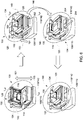
- FIG. 6 is a schematic perspective view of the breast imaging assembly 100 shown in a plurality of configurations, i.e., mammography configuration 132 and ultrasound configuration 134.
- breast imaging assembly 100 is initially shown in mammography configuration 132 with upper ultrasound assembly 124 in the raised position, lower ultrasound probe 146 (shown in FIGs. 3 and 4 ) in the parked position adjacent gantry 102 (shown in FIGs. 1 and 2 ) on first side 150 of lower compression paddle 118, and lower compression paddle 118 with lower ultrasound assembly 142 resting on x-ray detection device 108, a woman's breast (not shown in FIG. 6 ) is positioned between compression paddles 114 and 118.
- Lower ultrasound probe assembly 142 has a lateral length L LA and lower ultrasound probe 146 has a lateral length L LP .
- Lateral length L LA and lateral length L LP have any values that enable operation of breast imaging assembly 100 as described herein.
- lateral length L LA is approximately 30 cm from the left track 144 to the right track 144 and lateral length L LP is approximately 15 cm.
- lateral length L LA will have a value such that the surface area of lower ultrasound probe assembly 142 is greater than the active area of x-ray detection device 108.
- lower ultrasound probe 146 moves in a centered configuration along tracks 144 through upper ultrasound probe 124.
- lateral length L LP is not long enough to cover an entire breast (not shown in FIG. 4 ) laterally, then a second sweep may be performed. This can be configured by a technologist before the scan begins. If two sweeps of probe 146 are to be performed, probe 146 will be shifted to one side of assembly 142, a first scan performed, and then probe 146 will shift to the opposite side of assembly 142 and a second scan will be performed.
- the associated ultrasound imaging software is configured to facilitate seamless integration of the two sweeps of probe 146 without the need to reposition the patient.
- lateral length L LP is approximately 30 cm to facilitate more rapid scanning and seamless integration of the two sweeps of the probe. This concept can be used in single side or even supine imaging system.
- sweeps of probe 126 are lateral, i.e., from side to side. For many breasts, if the sweep is performed side to side, only one sweep will be needed.
- upper probe track 128 (shown in FIGs. 3-5 ) (to which upper ultrasound probe 126 is slidingly engaged) is rounded upward proximate a human patient (not shown in FIG. 6 ).
- lower probe track 144 (shown in FIGs. 3-5 ) (to which lower ultrasound probe 146 is slidingly engaged) is rounded downward proximate the human patient.
- lower ultrasound probe 146 moves from the parked position on first side 150 of lower compression paddle 118 toward second side 152 of lower compression paddle 118 as indicated by arrow 151. In some alternative embodiments, lower ultrasound probe 146 may be "parked" proximate second side 152 of lower compression paddle 118.
- lower compression paddle 118 with lower ultrasound assembly 142 translates, i.e., raises upward from x-ray detection device 108 toward x-ray source 104 (shown in FIGs. 1 and 2 ) substantially synchronously with upper compression paddle 114 as shown by arrow 153.
- any sequence of operation of ultrasound probes 126 and 146 that enables operation of breast imaging assembly 100 as described herein is used, including, without limitation, series sequential operation, i.e., either of probes 126 and 146 first, followed by the other.
- the range of translating motion is within, and including, approximately 1 cm and 3 cm, with the exemplary embodiment translating approximately 2 cm.
- the pivoting of upper ultrasound assembly 124, movement of lower ultrasound probe 146, and translation of paddles 114 and 118 occur substantially simultaneously and synchronously to facilitate decreasing the amount of time a woman must maintain her breasts between compression paddles 114 and 118 to reduce discomfort.
- pivoting, moving, and translating are executed in any sequence that enables operation of breast imaging assembly 100 as described herein.
- FIG. 7 is a schematic perspective view of translation back plate 120 used with breast imaging assembly 100 (shown in FIGs. 3 , 4 , and 6 ).
- Translation back plate 120 includes a casing 154, a pair of lateral handles 156, and a translation slot 158 defined in casing 154.
- Translation slot 158 receives upper compression paddle 114 (with upper ultrasound assembly 124 coupled thereto) and lower compression paddle 118 (with lower ultrasound assembly 142 coupled thereto) therein (all shown in FIGs. 3 , 4 , and 5 ).
- Casing 154 receives and houses equipment (not shown) necessary for the operation of breast imaging assembly 100 including compression system 112, mammography system 110, and ultrasound probe sub-system 122 (all shown in FIGs. 3 and 4 ) as described herein.
- Such equipment includes, without limitation, one or more translation drive motors (electric, hydraulic, or pneumatic) for synchronously translating upper compression paddle 114 and lower compression paddle 118 up and down as indicated by bi-directional translation arrow 121.
- translation drive motors electric, hydraulic, or pneumatic
- Such equipment also includes, without limitation, one or more translation drive motors (electric, hydraulic, or pneumatic) to pivot upper ultrasound assembly 124 between the lowered position and the raised position.
- Such equipment further includes, without limitation, movement drive motors (electric, hydraulic, or pneumatic) to move lower ultrasound probe 146 between first side 150 of lower compression paddle 118 and second side 152 of lower compression paddle 118.
- such equipment includes, without limitation, power supplies and/or converters and controller(s) to regulate and control the operation of breast imaging assembly 100 as described herein.
- FIG. 8 is a schematic view of an exemplary human patient 160 using breast imaging assembly 100.
- a breast 162 of patient 160 is positioned between upper compression paddle 114 and lower compression paddle 118.
- patient 160 is positioned on a translatable device 164, i.e., a lift and support device 164.
- translatable device 164 is a translatable platform and patient 160 stands on device 164.
- Device 164 is configured to translate synchronously with compression paddles 114 and 118 as breast imaging assembly 100 shifts from mammography configuration 132 to ultrasound configuration 134 as described above. Therefore, breast imaging assembly 100 facilitates execution of both x-ray scans and ultrasound scans while breast 162 remains substantially compressed with a similar compression during both procedures.
- some compression relaxation may be performed during the shift from the x-ray scan configuration to the ultrasound scan configuration to facilitate the compression paddle motion, to improve ultrasound probe contact with the breast or to improve patient comfort for example.
- the compression will be such to shape the breast and reduce the x-ray radiation dose in 3D imaging and for 2D imaging to reduce the overlapping tissue.
- the compression during the ultrasound examination will maintain the lateral position of the breast to improve image registration.
- upper compression paddle 114, lower compression paddle 118, and lift and support device 164 is synchronized through an integrated controller or control system (neither shown in FIG. 8 ).
- gantry 102 is configured to translate in one direction while paddles 114 and 118 translate in the opposite direction through the associated control scheme such that the position of breast 162 is substantially constant, given the general considerations described above.
- FIG. 9 is a schematic view of patient 160 using an alternative breast imaging assembly 200 that includes an alternative gantry 202.
- breast imaging assembly 200 and gantry 202 include additional control features, such as additional hardware, software, and firmware, to translate gantry 202 upward and downward while translating upper compression paddle 114 and lower compression paddle 118 in the opposite directions such that paddles 114 and 118 are substantially stationary with respect to patient 160 and breast 162.
- breast imaging assembly 200 In operation of breast imaging assembly 200, rather than solely translating upper compression paddle 114 and lower compression paddle 118 up and down to translate lower compression paddle 118 away from x-ray detection device 108, gantry 202, with x-ray detection device 108 coupled thereto, translates downward such that x-ray detection device 108 is lowered away from lower compression paddle 118.
- the range of translating motion in this alternative embodiment is within, and including, approximately 1centimeter (cm) and 3 cm, with this alternative embodiment translating approximately 2 cm.
- upper compression paddle 114 and lower compression paddle 118 are effectively stationary with any small relative movement of paddles 114 and 118 with respect to breast 162 provided to facilitate the comfort of the patient.
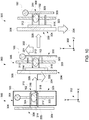
- upper ultrasound assembly 124 and lower ultrasound assembly 142 move from proximate patient 160 (shown in FIGs. 8 and 9 ) toward gantry 102 substantially simultaneously as shown by arrows 204 while scanning breast 162 (shown in FIGs. 8 and 9 ) using ultrasound techniques, including, without limitation, reflection mode and transmission mode. Transmission mode may be facilitated by the use of a lower frequency ultrasound probe than for reflection mode.
- upper compression paddle 114 and lower compression paddle 118 are separated to release breast 162 from compression and breast imaging assembly 100 is restored to mammography configuration 132 for either the other breast or the next patient.
- the compression on breast 162 will automatically be released when the ultrasound scanning is complete.
- the data from the ultrasound will be sent for reconstruction and the images reconstructed together to form a 3D ultrasound image of the breast.
- FIG. 10 is a schematic view of patient 160 using another alternative breast imaging assembly 300.
- a coordinate system 302 with an X-axis, a Y-axis, and a Z-axis is used.
- Breast imaging assembly 300 includes an ultrasound stand system 304.
- Ultrasound stand system 304 includes a compression stand gantry 306 that is shown in phantom in the left illustration to clarify that human patient 160 is behind gantry 306 and facing toward the reader of this disclosure in the direction of the z-axis.
- gantry 306 is primarily configured for ultrasound stand system 304 that is substantially separated from an independent mammography system 308.
- Mammography system 308 includes a mammography gantry 309 and is shown to the right of human patient 160 in the direction of the x-axis. As such, ultrasound stand system 304 and mammography system 308 are shown substantially orthogonal to each other. In some embodiments, mammography system 308 is fixedly mounted proximate ultrasound stand system 304. In other embodiments, mammography system 308 is portable, e.g., mounted on wheels to facilitate convenient removal from breast imaging assembly 300 when x-ray imaging is not desired.
- ultrasound stand system 304 also includes an upper (first) ultrasound assembly 310 that includes an upper (first) ultrasound paddle 312 and an upper (first) ultrasound probe 314.
- Ultrasound stand system 304 further includes a lower (second) ultrasound assembly 316 that includes a lower (second) ultrasound paddle 318 and a lower (second) ultrasound probe 320.
- mammography system 308 also includes an x-ray detection device 322 and an x-ray source (not shown).
- Mammography system 308 further includes an x-ray upper paddle 324.
- X-ray detection device 322 and x-ray upper paddle 324 are translatably coupled to mammography gantry 309 through a translation back plate (not shown) similar to translation back plate 120 (shown in FIGs. 3 and 4 ).
- upper ultrasound assembly 310 and lower ultrasound assembly 316 are translatably coupled to compression stand gantry 309 though a translation back plate 326 that is also similar to translation back plate 120.
- breast imaging assembly 300 starts in a mammography configuration 328.
- mammography configuration 328 human patient 160 has breast 162 compressed through upper ultrasound paddle 312 and lower ultrasound paddle 318.
- x-ray upper paddle 324 rests directly on top of upper ultrasound paddle 312 and lower ultrasound paddle 318 rests on top of x-ray detection device 322.
- breast imaging assembly 300 shifts from mammography configuration 328 to an ultrasound configuration 330.
- one or more translation drive motors (electric, hydraulic, or pneumatic) (not shown) translates x-ray upper paddle 324 through translation back plate 326 upward and away from upper ultrasound paddle 312 as shown by arrow 332.
- one or more translation drive motors (electric, hydraulic, or pneumatic) (not shown) translates mammography gantry 309 and x-ray detection device 322 through the associated translation back plate downward and away from lower ultrasound paddle 318 as shown by arrow 334.
- Breast 162 remains compressed through upper ultrasound paddle 312 and lower ultrasound paddle 318.
- X-ray upper paddle 324 is retracted away from patient 160, or removed from the associated translation back plate and mammography gantry 309, and compression stand gantry 306 shifts downward approximately 2 cm as indicated by arrow 336 while paddles 312 and 318 are maintained substantially stationary with respect to breast 162.
- upper ultrasound assembly 310 with upper ultrasound paddle 312 and upper ultrasound probe 314 are moved automatically or manually by the technologist on compression stand gantry 309.
- lower ultrasound assembly 316 with lower ultrasound paddle 318 and lower ultrasound probe 320 are moved automatically or manually by the technologist on compression stand gantry 306.
- Probes 314 and 320 scan breast 162 in the direction of the x-axis in the cranial caudal (CC) view or position.
- CC cranial caudal
- compression stand gantry 306 is positioned on front of patient 160 next to mammography gantry 309 or on the opposite side.
- Compression stand gantry 306 includes a pivot mechanism (not shown) such that the angulation of the oblique angle, nominally 45 degrees, may be matched.
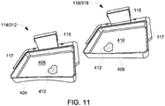
- FIG. 11 is a schematic perspective view of upper (first) compression paddles 114 and 312 and lower (second) compression paddles 118 and 318 that may be used with breast imaging assemblies 100 (shown in FIGs. 3 , 4 , 6 , and 8 ), 200 (shown in FIG. 9 ), and 300 (shown in FIG. 10 ).
- Upper compression paddles 118 and 318 include a frame 404 and lower compression paddles 118 and 318 include a frame 406, where frame 404 differs from frame 406 in that frame 404 is partially curved and frame 406 is substantially straight, where frame 404 better fits the overall shape of breast 162.
- Each frame 404 and 406 defines an open region 408 and 410, respectively.
- each open region 408 and 410 receives a mesh material 412 affixed to frames 404 and 406 to extend over open regions 408 and 410, respectively.
- Mesh material 412 is deformable relative to frames 404 and 406, thereby facilitating comfort of patient 160 when breast 162 (both shown in FIGs. 8 , 9 , and 10 ) is compressed, where mesh material 412 deforms around breast 162 to provide comfortable support.
- a plastic insert (not shown) may be used in paddle configuration 402 to give a predetermined breast compression if desired.
- Mesh material 412 has a substantially small attenuation coefficient for x-rays and ultrasound waves.
- FIG. 12 is a schematic side view of an alternative upper compression paddle 450 and lower compression paddle 452 that may be used with breast imaging assembly 100 (shown in FIGs. 3 and 4 ).
- upper compression paddle 450 includes a curved section 454 that is shaped to account for the natural curvature of breast 162. Curved section 454 facilitates improved ultrasound scanning of that portion of breast 162 closest to the torso of human patient 160 when breast 162 is compressed between paddles 450 and 452. Such improved ultrasound scanning is facilitated through providing a path of track for an ultrasound probe 456 that captures imaging of approximately 4 millimeters (mm) to approximately 5 mm that may be typically not captured without curved section 454.
- mm millimeters
- FIG. 13 is a schematic overhead view of an alternative compression paddle 500 including an exemplary ultrasound gel system 502 that may be used with breast imaging assembly 100 (shown in FIGs. 3 and 4 ).
- Upper compression paddles may be similarly configured.
- one of the issues solved by having a dual sided ultrasound scan is breast contact with the ultrasound waves.
- ultrasound scans typically require a coupling gel between the breast and the transducer for transmission.
- the coupling gel facilitates transmission of the high-frequency ultrasound waves, since air is a poor transmission medium and boundaries between air and water or tissues reflect most of the wave energy. Even thin layers of air or small bubbles significantly attenuate ultrasound transmission through them.
- compression paddle 500 includes a fluid-tight containment 504 that defines a fluid chamber 506 therein.
- Compression paddle 500 also includes ultrasound gel system 502 that includes a gel/water bladder 508 that defines a gel void 510 therein.
- Gel/water bladder 508 is fabricated of an ultrasound and x-ray transparent material, e.g., and without limitation, urethane.
- Ultrasound gel system 502 also includes a gel or water source 512 and gel/water bladder 508 is coupled to gel/water source 512 through a gel/water tube 514.
- gel/water bladder 508 is filled with air 516 at atmospheric pressure.
- Fluid chamber 506 is filled with air 516 at or near atmospheric pressure.
- Compression paddle 500 and ultrasound gel system 502 include sufficient fluid transfer devices to inject water and gel into, and vent air from, fluid chamber 506 and gel/water bladder 508 as well as remove water and gel from, and permit air entry into, fluid chamber 506 and gel/water bladder 508.
- gel/water bladder 508 is inflated with air 516 during the x-ray imaging and then filled with ultrasound gel 520 during the ultrasound imaging. This facilitates producing better coupling on the edges of breast 162 without compromising the x-ray or ultrasound image quality. Furthermore it will serve to protect x-ray detector device 108 (shown in FIGs. 3 , 4 , 8 , and 9 ) from damage by ultrasound gel 520. Inflating gel/water bladder 508 with air 516 during x-ray imaging facilitates more accurate registration of the x-ray and ultrasound images as breast 162 will not move substantially between the two different acquisitions. It may also provide added comfort to human patient 160 (shown in FIGs. 8 , 9 , and 10 ) as the compression force will be more uniformly distributed over breast 162 and thus decreasing the pressure on any one area.
- FIG. 14 is a schematic overhead view of another alternative compression paddle 600 including an alternative ultrasound gel and gel dam system 602 that may be used with breast imaging assembly 100 (shown in FIGs. 3 and 4 ).
- FIG. 15 is a schematic side view of compression paddle 600 and ultrasound gel and gel dam system 602.
- compression paddle 600 includes mesh material 412.
- Compression paddle 600 also includes ultrasound gel system 602 that includes a fabric belt 604 fabricated from a material, e.g., and without limitation, urethane or butyl rubber that may or may not be ultrasound and x-ray transparent. Fabric belt 604 is coupled to corners 606 and 608 of paddle 600.
- Fabric belt 604 is configured to act as a belt that, after the x-ray, will pull gel 620 around the tissue of breast 162 a small amount to make gel 620 conform to breast 162 such that air gaps are removed and, in some cases, breast 162 is more uniform in thickness. Fabric belt 604 and gel 620 conform to breast 162 and define a void 610 therebetween. Ultrasound gel system 602 also includes a gel source 612 and void 610 is coupled to gel source 612 through a gel tube 614. Some embodiments of ultrasound gel system 602 also include devices such as a plurality of push rods 616 that facilitate the uniformity of gel elimination of air gaps around breast 162 in cooperation with fabric belt 604. Push rods 616 cooperate with gel 620 and fabric belt 604 to facilitate the uniformity of breast 162 and more complete high quality ultrasound images of breast 162. Breast 162 will not move substantially between the two different acquisitions.
- void 610 is filled with air (not shown in FIGs. 14 and 15 ) at atmospheric pressure.
- gel 620 is injected into void 610 while air is vented therefrom through the mesh paddles and around fabric strap 616.
- additional gel may be added by hand or by a mound of gel placed in front of the top ultrasound transducer before scanning commences.
- a dispenser in front of the top ultrasound transducer may be placed in front of the top ultrasound transducer before and during scanning.
- Lower compression paddle 600 and ultrasound gel system 602 include sufficient fluid transfer devices to inject gel 620 into, and vent air from, paddle 600 as well as remove gel 620 from, and permit air entry into, paddle 600.
- FIG. 16 is a schematic view of an exemplary control system 700 that may be used with breast imaging assembly 100 (shown in FIGs. 3 and 4 ).
- Control system 700 includes at least one controller 702.
- Controller 702 regulates and synchronizes operation of the devises described above to facilitate expedient x-ray and ultrasound scanning and facilitate comfort of human patient 160.
- controller 702 communicates with x-ray system control which controls x-ray source 104 and x-ray detection device 108. Controller 702 transmits command signals 704 to, and receives feedback signals 706 from, the x-ray system control which transmits command signals to x-ray source 104 and detection device 108, and the associated drive and measurement devices thereof.
- controller 702 communicates with upper compression paddle 114, lower compression paddle 118, upper ultrasound assembly 124, and lower ultrasound assembly 142. Controller 702 transmits command signals 708 to, and receives feedback signals 710 from, paddles 114 and 118 and assemblies 124 and 142, and the associated drive and measurement devices thereof. Further, controller 702 communicates with pivot mechanism 136, where controller 702 transmits command signals 712 to, and receives feedback signals 714 from, pivot mechanism 136, and the associated drive and measurement devices thereof.
- controller 702 communicates with ultrasound gel system 502, where controller 702 transmits command signals 716 to, and receives feedback signals 718 from, ultrasound gel system 502, and the associated drive and measurement devices thereof.
- controller 702 communicates with translatable device 164, where controller 702 transmits command signals 720 to, and receives feedback signals 722 from, translatable device 164, and the associated drive and measurement devices thereof.
- controller 702 communicates with the ultrasound system control which transmits signals to upper ultrasound probe 126 and lower ultrasound probe 146, where ultrasound system controller 702 transmits command signals 724 to, and receives feedback signals 726 from, probes 126 and 146, and the associated drive and measurement devices thereof.
- controller 702 does not control x-ray image acquisition or ultrasound image acquisition. Rather, in contrast, an x-ray system control scheme and an ultrasound system control scheme controls those features. Controller 702 for systems 100 and 200 have a "handshaking" relationship with the x-ray system control scheme and an ultrasound system control scheme.
- controller 702 sends signals to, and receives signals from, the x-ray system control scheme and the ultrasound system control scheme and, optionally, a gantry system control scheme of the x-ray system.
- the signals from controller 702 are limited to start and stop imaging and movement of gantry 102/202.
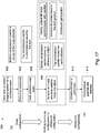
- FIG. 17 is an exemplary method 800 of imaging an object through operating breast imaging assembly 100 (shown in FIGs. 3 and 4 ).
- a medical technologist (not shown) sets up 802 breast imaging system 100 for a combined examination including x-ray and ultrasound scanning and imaging.
- Breast imaging system 100 is initially set up in tomosynthesis x-ray configuration 132 with upper ultrasound assembly 124 in the raised position, upper compression paddle 114 in a raised position above lower compression paddle 118, lower ultrasound probe 146 in the parked position adjacent gantry 102 on first side 150 of lower compression paddle 118, and lower compression paddle 118 with lower ultrasound assembly 142 resting on x-ray detection device 108.
- breast imaging assembly 100 is set up in mammography x-ray configuration 132
- patient 160 is positioned 804 on translatable device 164, i.e., lift and support device 164.
- Lift and support device 164 is positioned at a height proper for comfortable positioning and compression of breast 162.
- Breast 162 is positioned within mesh material 412 on lower compression paddle 118 and upper compression paddle 114, also with mesh material 412, is lowered to compress breast 162 and adjusts the x-ray gantry height through the x-ray system control scheme.
- the technologist manually adjusts paddles 114 and 118 to properly compress breast 162.
- the technologist uses control system 700 and controller 702 to position lift and support device 164 through drive motor command signals 720 and lift and support device position feedback measurement signals 722, and position upper compression paddle 114 through motor command signals 708 and paddle position feedback measurement signals 710. Under some circumstances, lower compression paddle 118, and possible x-ray detection device 108 may also need to be height adjusted.
- the technologist uses the x-ray system control scheme to energize x-ray source 104 and transmit x-rays (not shown) through upper paddle 114 (upper ultrasound assembly 124 is pivoted out of the x-ray transmission path), breast 162, and lower paddle 118 to x-ray detection device 108.
- Mesh material 412 presents a relatively small attenuation of the x-rays. The resultant x-ray image data is collected and stored for subsequent imaging.
- controller 702 shifts 808 breast imaging assembly 100 from x-ray configuration 132 to ultrasound configuration 134.
- upper ultrasound assembly 124 pivots down to the lowered position on top of upper paddle 114 as a function of command signal 712 to the associated drive motor (not shown) and feedback signals 714.
- upper ultrasound probe 126 moves to the ultrasound start position proximate patient 160 as a function of command signal 724 to the associated drive motor (not shown) and feedback signals 726.
- lower ultrasound probe 146 moves from the parked position on first side 150 of lower compression paddle 118 toward second side 152 of lower compression paddle 118 as a function of command signal 724 to the associated drive motor (not shown) and feedback signals 726.
- lower compression paddle 118 with lower ultrasound assembly 142 translates, i.e., raises upward to its ultrasound height from x-ray detection device 108 toward x-ray source 104 substantially synchronously with upper compression paddle 114, also translating to its ultrasound height, as a function of command signal 708 to the associated drive motor (not shown) and feedback signals 710.
- the range of translating motion is within, and including, approximately 1 cm and 3 cm, with the exemplary embodiment translating approximately 2 cm.
- breast imaging assembly 100 shifts from mammography configuration 132 to ultrasound configuration 134, with breast 162 of patient 160 maintained between upper compression paddle 114 and lower compression paddle 118, lift and support device 164 translates synchronously with compression paddles 114 and 118 as a function of command signal 720 to the associated drive motor (not shown) and feedback signals 722. Therefore, breast imaging assembly 100 facilitates execution of both x-ray scans and ultrasound scans while breast 162 remains substantially compressed with a similar compression during both procedures. Some compression relaxation may be performed during the shift from the x-ray scan configuration to the ultrasound scan configuration for the comfort of patient 160.
- fluid chamber 506 and gel/water bladder 508 are filled with air 516 at atmospheric pressure.
- air 516 is filled with air 516 at atmospheric pressure.
- sufficient gel 520 for ultrasound imaging surrounds breast 162 in lower compression paddle 500 at least partially due to breast 162 substantially conforming to lower compression paddle 500 due to gravity and force induced on breast 162 by upper compression paddle 114.
- lower ultrasound probe 146 and upper ultrasound probe 126 scan (sweep) 810 breast 162 substantially simultaneously as a function of command signal 724 to the associated drive motor (not shown) and feedback signals 726 to capture ultrasound data for storage and subsequent imaging.
- the stored ultrasound image data and the stored x-ray image data are co-registered with standard deformable registration techniques.
- compression paddles 114 and 118 are released 812 as a function of command signals 708 and feedback 710 such that upper compression paddle 114 raises and lower compression paddle 118 returns to the top of x-ray detection device 108 such that patient 160 can withdraw breast 162.
- imaging systems include additional components known to those skilled in the art and not described herein. Such additional components are not essential for describing the aspects of operation of the imaging systems as described herein, and are therefore excluded.
- the above-described breast imaging systems include enhancements to existing x-ray systems to include features that facilitate significant reductions in the shifting of the breast being imaged between the x-ray imaging and ultrasound imaging.
- the breast imaging systems described herein integrate x-ray imaging and ultrasound imaging on the same machine with substantially the same compression induced on the breast being imaged and substantially similar positions for both images.
- the breast imaging systems described herein are configured such that the detector is movable separate from the compression system such that the compression system and gantry may be moved in a synchronized fashion where the detector is lowered and the patient remains in compression and does not move significantly.
- the compression system couples to the mammography gantry as an attachment to the compression arm such that the compression system operates separately or in conjunction with the existing mammography compression system.
- the embodiments described herein use two ultrasound probes and scan from the top of the breast and then the bottom of the breast. Such dual-sided ultrasound scanning without interfering with the x-ray imaging detector is facilitated with a mechanism to move the breast upward with the upper and lower ultrasound transducers without hurting the woman while she is compressed. Therefore, the breast can remain in standard mammography configuration in close proximity to the x-ray detector.
- the gantry including the x-ray detector are moved downward slightly and the two compression paddles move together such that the net effect on the breast is that the breast is merely lifted slightly.
- the geometry of the breast to detector and tube motion is not altered and no modification of the tomosynthesis reconstruction techniques are required.
- the gantry including the x-ray detector are moved downward slightly and the two compression paddles move together such that the net motion effect on the breast is less than the 3 cm required for the ultrasound probe.
- the two compression paddles include a mesh material that contacts the breast to support it without significantly the x-ray or ultrasound transmission and allowing for ultrasound coupling gel to penetrate to the breast.
- small bladders are integrated into the compression paddles such that when the x-ray image the gantry moves, the paddles move and the little bladder in each paddle fills with ultrasound gel or water such that good contact with the breast for the ultrasound is facilitated.
- the systems described herein are compatible with existing mammography and tomosynthesis systems and may be installed as a retrofit upgrade without modification to the x-ray system.
- An exemplary technical effect of the methods, systems, and apparatus described herein may include at least one of: (a) facilitate integration of x-ray breast imaging systems with ultrasound imaging systems; (b) facilitate significant reductions in repositioning of a woman's breast for an ultrasound exam after an x-ray scan; (c) automatically inject ultrasound gel into a bladder within the upper and lower ultrasound paddles to improve ultrasound probe contact with the breast; (d) using a mesh on each of the lower and upper ultrasound paddles to allow for ultrasound coupling gel to make contact with both the ultrasound probe and the patient skin; (e) reducing a number of patient visits for breast cancer screening exams; (f) reducing the time required to acquire and analyze results of integrated x-ray and ultrasound exams; (g) reducing cost and length of time for an ultrasound scan; (h) reducing errors associated with repositioning the patient; (i) improving co-registration of x-ray and ultrasound images with standard deformable registration techniques, thereby improving diagnoses and/or reducing time and skill required by a medical professional for analysis of acquired
- Exemplary embodiments of breast imaging systems, and methods of operating such systems and devices are not limited to the specific embodiments described herein, but rather, components of systems and/or steps of the methods may be utilized independently and separately from other components and/or steps described herein.
- the methods may also be used in combination with other systems requiring sequential imaging and the associated methods, and are not limited to practice with only the breast imaging system and methods as described herein. Rather, the exemplary embodiment can be implemented and utilized in connection with many other sequential imaging applications.
- Such devices typically include a processor, processing device, or controller, such as a general purpose central processing unit (CPU), a graphics processing unit (GPU), a microcontroller, a reduced instruction set computer (RISC) processor, an application specific integrated circuit (ASIC), a programmable logic circuit (PLC), a field programmable gate array (FPGA), a digital signal processing (DSP) device, and/or any other circuit or processing device capable of executing the functions described herein.
- the methods described herein may be encoded as executable instructions embodied in a computer readable medium, including, without limitation, a storage device and/or a memory device. Such instructions, when executed by a processing device, cause the processing device to perform at least a portion of the methods described herein.
- the above examples are exemplary only, and thus are not intended to limit in any way the definition and/or meaning of the term processor and processing device.
Landscapes
- Health & Medical Sciences (AREA)
- Life Sciences & Earth Sciences (AREA)
- Medical Informatics (AREA)
- Engineering & Computer Science (AREA)
- Animal Behavior & Ethology (AREA)
- Molecular Biology (AREA)
- Biophysics (AREA)
- Nuclear Medicine, Radiotherapy & Molecular Imaging (AREA)
- Veterinary Medicine (AREA)
- Pathology (AREA)
- Radiology & Medical Imaging (AREA)
- Biomedical Technology (AREA)
- Heart & Thoracic Surgery (AREA)
- Public Health (AREA)
- Surgery (AREA)
- Physics & Mathematics (AREA)
- General Health & Medical Sciences (AREA)
- High Energy & Nuclear Physics (AREA)
- Optics & Photonics (AREA)
- Dentistry (AREA)
- Oral & Maxillofacial Surgery (AREA)
- Ultra Sonic Daignosis Equipment (AREA)
- Apparatus For Radiation Diagnosis (AREA)
Abstract
Description
- The field of the disclosure relates generally to breast imaging systems, and, more particularly, to breast imaging systems including ultrasound and x-ray using a dual-sided compression paddle system and the methods of operation for acquiring breast images.
- Breast cancer screening is performed with x-ray imaging in either two-dimensional, i.e., mammography, and in recent years, tomosynthesis (three-dimensional x-ray). For many women, such x-ray screening is sufficient for generating images that are satisfactory for review by a medical professional. However, many women have a high percentage of dense breast tissues which do not show contrast versus cancerous tissues and additional screening is performed through ultrasound imaging. Ultrasound imaging is often performed in a supine position whereas the x-ray mammography is performed with the women upright with the breast in a compressed position. Such shifting of position of the patient shifts the shape and the tissue of the breast making any registration of the two imaging modalities difficult. As a result, significant discrepancies between the findings in the mammography and the ultrasound images may require further imaging to resolve and my lead to unnecessary biopsies. Therefore, it is highly desirable to perform the mammography or tomosynthesis imaging in the exact same positioning at the same time as the ultrasound imaging. To perform ultrasound imaging, the ultrasound probe must be in contact with the tissue or a coupling medium such as ultrasound gel or lotion or water. However, if the ultrasound gel is applied to the breast prior to taking the x-ray image it may result in artifacts in the x-ray image.
- In addition, in order to achieve high x-ray image quality, either mammography or tomosynthesis, one must have as small of a distance between the x-ray detector and the breast as possible. Therefore, to preserve optimal image quality between x-ray imaging and ultrasound imaging one must move the ultrasound transducer and coupling medium between the x-ray source and/or detector and the breast.
- Previous attempts to design breast screening systems that integrate both x-ray and ultrasound technologies have had not completely addressed the workflow and image quality needed in both the mammography and ultrasound. In previous examples, the woman's breast is compressed as for standard mammography imaging and the x-ray image acquired. Upon completion of the x-ray image the breast is scanned with the ultrasound probe on top of the compression paddle on the breast. This configuration gives very good mammography image quality. However, the ultrasound image quality is degraded as resolution is limited by the frequency of the ultrasound due to an inverse relationship between the frequency of the ultrasound signals and the penetration depth of the sound waves, i.e., the sound attenuation is proportional to the frequency and higher frequency ultrasound may not adequately penetrate the breast tissue. In most breast-compressed thicknesses the ultrasound frequency needed to fully penetrate the breast does not give sufficient imaging resolution to detect small masses and calcifications.
- In other systems, where the breast is scanned from below, the ultrasound attenuation issue described above remains and additionally coupling medium for the ultrasound probe absorbs a significant portion of the x-rays after exposing the patient. This results in necessitating a higher x-ray dose to the patient. Furthermore the distance between the x-ray detector and the patient is increased. This may result in degradation of the x-ray image quality as well.
- Dual sided scanning with ultrasound on a separate system in the mammography configuration has also been demonstrated. In this configuration the ultrasound image quality has been preserved. However, the workflow and image registration have proven difficult, since movement of the breast being imaged is likely. It is highly desirable to incorporate the high image quality of dual sided ultrasound scanning in the mammography configuration without requiring the use of a separate system. In order to perform dual sided ultrasound scanning of the breast on a mammography system, one solution is to include features that move the x-ray detector out of the way such that the ultrasound probe can be moved into position once x-ray imaging has been performed. However, for many known x-ray systems the detector is attached x-ray system gantry and does not move. For these systems an ultrasound only add-on is highly desirable.
- In one aspect according to the present invention, an imaging assembly is provided. The imaging assembly includes a gantry and a compression system configured to receive and compress an object to be imaged. The compression system includes a first compression paddle coupled to the gantry and a second compression paddle coupled to the gantry. The imaging assembly also includes an x-ray detection device coupled to the gantry. The X-ray detection device is proximate the second compression paddle. The imaging assembly further includes an ultrasound system including a first ultrasound probe coupled to the first compression paddle. The first ultrasound probe is coupled to the first compression paddle. The first ultrasound probe is configured to acquire a first portion of the ultrasound image information of the object to be imaged. The ultrasound system also includes a second ultrasound probe coupled to the second compression paddle. The second ultrasound probe is configured to acquire a second portion of the ultrasound image information of the object to be imaged.
- In a further aspect, a retrofit upgrade package for an installed legacy imaging system is provided. The retrofit upgrade package includes a compression system configured to receive and compress an object to be imaged. The compression system includes a first compression paddle configured to be coupled to a gantry and a second compression paddle configured to be coupled to the gantry. The retrofit upgrade package also includes an ultrasound system including a first ultrasound probe coupled to the first compression paddle. The first ultrasound probe is coupled to the first compression paddle. The first ultrasound probe is configured to acquire a first portion of ultrasound image information of the object to be imaged. The ultrasound system also includes a second ultrasound probe coupled to the second compression paddle. The second ultrasound probe is configured to acquire a second portion of the ultrasound image information of the object to be imaged.
- In another aspect, a method of imaging an object is provided. The method includes positioning a first compression paddle to receive an object to be imaged and positioning a second compression paddle to extend over at least a portion of an x-ray detector. The method also includes positioning the object to be imaged between the first compression paddle and the second compression paddle. The method further includes generating x-ray image data of the object to be imaged. The method also includes translating the first compression paddle and the second compression paddle substantially synchronously with the object to be imaged remaining therebetween. The method further includes moving a first ultrasound probe across the first compression paddle and moving a second ultrasound probe across the second compression paddle substantially simultaneously.
- Various features, aspects, and advantages of the present disclosure will become better understood when the following detailed description is read with reference to the accompanying drawings in which like characters represent like parts throughout the drawings, wherein:
-
FIG. 1 is a perspective schematic view of a known breast imaging assembly; -
FIG. 2 is a another perspective schematic view of the known breast imaging assembly; -
FIG. 3 is a front schematic perspective view of an exemplary breast imaging assembly; -
FIG. 4 is a side schematic view of the breast imaging assembly shown inFIG. 3 ; -
FIG. 5 is a schematic perspective view of an exemplary upper ultrasound probe assembly that may be used with the breast imaging assembly shown inFIGs. 3 and4 ; -
FIG. 6 is a schematic perspective view of the breast imaging assembly shown inFIGs. 3 and4 in a plurality of configurations; -
FIG. 7 is a schematic perspective view of an exemplary translation back plate that may be used with the breast imaging assembly shown inFIGs. 3 and4 ; -
FIG. 8 is a schematic view of an exemplary patient using the breast imaging assembly shown inFIGs. 3 and4 with an exemplary lift and support device; -
FIG. 9 is a schematic view of the patient shown inFIG. 8 using an alternative breast imaging assembly with gantry control synchronized to the compression system; -
FIG. 10 is a schematic view of the patient shown inFIGs. 8 and9 using another alternative breast imaging assembly; -
FIG. 11 is a schematic perspective view of an exemplary upper compression paddle and lower compression paddle that may be used with the breast imaging assembly shown inFIGs. 3 and4 ; -
FIG. 12 is a schematic side view of an alternative upper compression paddle and lower compression paddle that maybe used with the breast imaging assembly shown inFIGs. 3 and4 ; -
FIG. 13 is a schematic overhead view of an alternative compression paddle including an exemplary ultrasound gel system that may be used with the breast imaging assembly shown inFIGs. 3 and4 ; -
FIG. 14 is a schematic overhead view of another alternative compression paddle including an alternative ultrasound gel and gel dam system that may be used with the breast imaging assembly shown inFIGs. 3 and4 ; -
FIG. 15 is a schematic side view of the compression paddle and the alternative ultrasound gel and gel dam system shown inFIG. 14 ; -
FIG. 16 is a schematic view of an exemplary control system that may be used with the breast imaging assembly shown inFIGs. 3 and4 ; and -
FIG. 17 is an exemplary method of imaging an object through operating the breast imaging assembly shown inFIGs. 3 and4 . - Unless otherwise indicated, the drawings provided herein are meant to illustrate features of embodiments of the disclosure. These features are believed to be applicable in a wide variety of systems comprising one or more embodiments of the disclosure. As such, the drawings are not meant to include all conventional features known by those of ordinary skill in the art to be required for the practice of the embodiments disclosed herein.
- In the following specification and the claims, reference will be made to a number of terms, which shall be defined to have the following meanings.
- The singular forms "a", "an", and "the" include plural references unless the context clearly dictates otherwise.
- "Optional" or "optionally" means that the subsequently described event or circumstance may or may not occur, and that the description includes instances where the event occurs and instances where it does not.
- Approximating language, as used herein throughout the specification and claims, may be applied to modify any quantitative representation that could permissibly vary without resulting in a change in the basic function to which it is related. Accordingly, a value modified by a term or terms, such as "about", "approximately", and "substantially", are not to be limited to the precise value specified. In at least some instances, the approximating language may correspond to the precision of an instrument for measuring the value. Here and throughout the specification and claims, range limitations may be combined and/or interchanged, such ranges are identified and include all the sub-ranges contained therein unless context or language indicates otherwise.
- As used herein, the terms "processor" and "computer," and related terms, e.g., "processing device," "computing device," and "controller" are not limited to just those integrated circuits referred to in the art as a computer, but broadly refers to a microcontroller, a microcomputer, a programmable logic controller (PLC), and application specific integrated circuit, and other programmable circuits, and these terms are used interchangeably herein. In the embodiments described herein, memory may include, but it not limited to, a computer-readable medium, such as a random access memory (RAM), a computer-readable non-volatile medium, such as a flash memory.
- Alternatively, a floppy disk, a compact disc - read only memory (CD-ROM), a magneto-optical disk (MOD), and/or a digital versatile disc (DVD) may also be used. Also, in the embodiments described herein, additional input channels may be, but are not limited to, computer peripherals associated with an operator interface such as a mouse and a keyboard. Alternatively, other computer peripherals may also be used that may include, for example, but not be limited to, a scanner. Furthermore, in the exemplary embodiment, additional output channels may include, but not be limited to, an operator interface monitor.
- Further, as used herein, the terms "software" and "firmware" are interchangeable, and include any computer program storage in memory for execution by personal computers, workstations, clients, and servers.
- As used herein, the term "non-transitory computer-readable media" is intended to be representative of any tangible computer-based device implemented in any method of technology for short-term and long-term storage of information, such as, computer-readable instructions, data structures, program modules and sub-modules, or other data in any device. Therefore, the methods described herein may be encoded as executable instructions embodied in a tangible, non-transitory, computer-readable medium, including, without limitation, a storage device and/or a memory device. Such instructions, when executed by a processor, cause the processor to perform at least a portion of the methods described herein. Moreover, as used herein, the term "non-transitory computer-readable media" includes all tangible, computer-readable media, including, without limitation, non-transitory computer storage devices, including without limitation, volatile and non-volatile media, and removable and non-removable media such as firmware, physical and virtual storage, CD-ROMS, DVDs, and any other digital source such as a network or the Internet, as well as yet to be developed digital means, with the sole exception being transitory, propagating signal.
- Furthermore, as used herein, the term "real-time" refers to at least one of the time of occurrence of the associated events, the time of measurement and collection of predetermined data, the time to process the data, and the time of a system response to the events and the environment. In the embodiments described herein, these activities and events occur substantially instantaneously.
- In addition, as used herein, the terms "mammography", sometimes used to refer to a two-dimensional x-ray system, and "tomography", sometimes used to refer to a three-dimensional x-ray system, are used interchangeably. To facilitate clarity, the term "mammography" is used herein to generally refer to x-ray-based imaging systems, and, if necessary to differentiate the two systems, the term tomography, or a variant thereof, will be used.
- The embodiments of the breast imaging systems described herein overcome many of the deficiencies of known x-ray and ultrasound imaging systems. The breast imaging systems described herein include enhancements to existing x-ray systems to include features that facilitate significant reductions in the shifting of the breast being imaged between the x-ray imaging and ultrasound imaging. Specifically, the breast imaging systems described herein integrate x-ray imaging and ultrasound imaging on the same machine with substantially the same compression induced on the breast being imaged and substantially similar positions for both images. As such, the breast imaging systems described herein are configured such that the detector is movable separate from the compression system such that the compression system and gantry may be moved in a synchronized fashion where the detector is lowered and the patient remains in compression and does not move significantly. Also, as such, the compression system couples to the mammography gantry as an attachment to the compression arm such that the compression system operates separately or in conjunction with the existing mammography compression system. More specifically, the embodiments described herein use two ultrasound probes and scan from the top of the breast and the bottom of the breast. Such dual-sided ultrasound scanning without interfering with the x-ray imaging detector is facilitated with a mechanism to move the breast upward with the upper and lower ultrasound transducers without hurting the woman while she is compressed.
- In an alternative embodiment, the x-ray detector is moved downward more than 1 centimeter (cm) but less than 10 cm after the x-ray examination to facilitate providing room for the ultrasound transducer. Therefore, the breast can be as close as possible to the x-ray detector and by placing the x-ray detectors as close to the breast as possible, the quality of x-ray images is not degraded from a non-coupled examination. Once the x-ray portion of the exam is completed, the gantry, including the x-ray detector, is moved downward slightly and the two compression paddles move together such that the net effect on the breast is as small as possible. In addition, the two compression paddles are composed in part of a mesh material that contacts the breast to support it and apply compression and tissue immobilization. Further, small bladders are integrated into the compression paddles such that when the x-ray image is complete, the gantry moves, the paddles move and the little bladder in each paddle fills with ultrasound gel, water, or other ultrasound conductive material such that good contact with the breast for the ultrasound is facilitated. The systems described herein are compatible with existing mammography systems and may be installed as a retrofit upgrade without modification to the legacy x-ray system.
- In the case of a retrofit upgrade to an existing x-ray mammography system, an add-on compression device may be used. This compression device will replace, or in some cases, work in conjunction with the existing compression system. The retrofit device attaches to the x-ray gantry as an attachment to the x-ray detector image receptor mechanism, preferably. The retrofit system consists of a compression device which includes one or two motors to drive two compression paddles independently. The compression paddles are such that the bottom compression paddle rests on the x-ray image receptor during x-ray imaging and is moved in conjunction with the top compression paddle before ultrasound imaging to allow room for the ultrasound transducer to move into contact with the breast. The compression paddles are controlled by a controller which also is in communication with the x-ray gantry or a patient lift device. The controller controls the movement of the compression paddles and gantry of the lift device such that the speed and distance movement of the compression paddles is parallel to that of the movement of the gantry or patient lift device. Once the x-ray portion of the exam is completed, the gantry including the x-ray detector are moved downward slightly and the two compression paddles move together such that the net effect on the breast is as small as possible and the compression plates remain parallel.
- Thus the patient breast location relative to the patient body does not move substantially.
-
FIG. 1 is a perspective schematic view of a knownbreast imaging assembly 50.FIG. 2 is a another perspective schematic view of knownbreast imaging assembly 50. Knownbreast imaging system 50 includes a known combined compression system/ultrasound assembly 60 that includes a known combined compression paddle/ultrasound probe 65 (both only shown inFIG. 1 ).Breast imaging assembly 50 includes agantry 102 and anx-ray source 104 coupled togantry 102.Breast imaging assembly 50 further includes anx-ray detection device 108 that is aligned withx-ray source 104, wherex-ray source 104,x-ray detection device 108, andgantry 102 define a mammography system 110.Breast imaging assembly 50 also includes agantry translation cradle 127, a pair ofcable conduits 129coupling detector 108 to x-raysource 104, and agantry translation slot 131 defined withingantry 102 that receivesgantry translation cradle 127. Both combined compression/ultrasound assembly 60 andx-ray detection device 108 are coupled togantry translation cradle 127, andassembly 60 anddetector device 108 translate up and down withcradle 127 throughslot 131 as necessary to adjust to a patient as a function of the patient's height and other anatomical features. -
FIG. 3 is a front schematic perspective view of an exemplarybreast imaging assembly 100.FIG. 4 is a side schematic view ofbreast imaging assembly 100.Breast imaging assembly 100 includesgantry 102 andx-ray source 104 coupled togantry 102, where is some embodiments,x-ray source 104 is substantially stationary, and in other embodiments,x-ray source 104 rotates upon an axis (not shown) to facilitate tomosynthesis imaging.Breast imaging assembly 100 further includesx-ray detection device 108 that is aligned withx-ray source 104, wherex-ray source 104,x-ray detection device 108, andgantry 102 define mammography system 110. - In the exemplary embodiment,
breast imaging assembly 100 includes acompression system 112 configured to receive and compress an object to be imaged, e.g., and without limitation, a woman's breast.Compression system 112 includes a first, i.e.,upper compression paddle 114 translatably coupled togantry 102 through agantry mounting plate 116, and a translation backplate 120.Compression system 112 also includes a plurality of paddle positioning motors (not shown) positioned withingantry 102 and motor control features to facilitate precise positioning ofpaddles 114 and 118 (the motors and motor control are discussed further below). A paddle slidingengagement device 117 facilitatescoupling paddle 114 togantry mounting plate 116.Compression system 112 also includes a second, i.e.,lower compression paddle 118 translatably coupled togantry 102 though translation backplate 120. As described further below, translation backplate 120 facilitates vertical translation oflower compression paddle 118 andupper compression paddle 114 as indicated bybi-directional translation arrow 121. -
Lower compression paddle 118 andx-ray detection device 108 are positioned proximate each other andlower compression paddle 118 rests on top ofx-ray detection device 108 whenbreast imaging assembly 100 is in a mammography configuration (not shown inFIGs. 3 and4 ) in contrast to an ultrasound configuration (as shown inFIGs. 3 and4 ), where both configurations are discussed further below. - Also, in the exemplary embodiment,
breast imaging assembly 100 includes anultrasound probe sub-system 122. In the exemplary embodiment,compression system 112 and ultrasound probe-sub system 122 are integrated to define a combined compression/ultrasound assembly 125.Ultrasound probe sub-system 122 includes a first, i.e.,upper ultrasound assembly 124 that includes a first, i.e., anupper probe track 128 to whichupper ultrasound probe 126 is slidingly engaged, i.e., movably mounted on such that it can be moved across the top ofpaddle 114.Upper ultrasound probe 126 includes motion control features and devices (not shown) that facilitate movingprobe 126 alongupper probe track 128 in the directions indicated bybi-directional arrow 130.Upper ultrasound probe 126 is configured to acquire a first portion of the ultrasound image information of the object to be imaged. - Further, in the exemplary embodiment,
breast imaging assembly 100 includes gantry translation cradle 127 (shown inFIGs. 1 and2 ), cable conduits 129 (shown inFIGs. 1 and2 )coupling detector 108 to x-raysource 104, and gantry translation slot 131 (shown inFIGs. 1 and2 ) defined withingantry 102 that receivesgantry translation cradle 127. Both combined compression/ultrasound assembly 125 andx-ray detection device 108 are coupled togantry translation cradle 127, andassembly 125 anddetector device 108 translate up and down withcradle 127 throughslot 131 as necessary to adjust to a patient as a function of the patient's height and other anatomical features. Therefore, combined compression/ultrasound assembly 125 is configured to replace combined compression system/ultrasound assembly 60 (shown inFIG. 1 ) withingantry translation cradle 127 and combined compression/ultrasound assembly 125 is compatible with knownx-ray detection device 108, also configured to reside ingantry translation cradle 127. As such, combined compression/ultrasound assembly 125 is configured to facilitate retrofit upgrades to known breast imaging assembly 50 (shown inFIG. 1 ) and other known breast imaging assemblies and combined compression/ultrasound assembly 125 may be installed on legacy breast imaging assemblies as at least a portion of a retrofit upgrade package. -
FIG. 5 is a schematic perspective view ofupper ultrasound assembly 124 in a mammography configuration 132 (not shown inFIGs. 3 and4 ) and an ultrasound configuration 134 (also, as shown inFIGs. 3 and4 ).Upper ultrasound assembly 124 includes apivot mechanism 136 that pivotably mountsupper ultrasound assembly 124 toupper compression paddle 114.Upper ultrasound assembly 124 is configured to be positioned betweenx-ray source 104 and x-ray detector 108 (both shown inFIGs. 3 and4 ), whereupper ultrasound assembly 124 is configured to pivot, i.e., flip from a first position, i.e.,ultrasound configuration 134 extending over at least a portion ofupper compression paddle 114 to a second position, i.e.,mammography configuration 132proximate gantry 102.Arrow 138 indicates this pivoting movement. Inmammography configuration 132,upper ultrasound probe 126 is substantially removed from an x-ray beam (not shown) emanated fromx-ray source 104 towardx-ray detection device 108 such thatupper ultrasound probe 126 does not interfere with tomographic imaging of the object being imaged.Upper ultrasound assembly 124 is also configured to pivot frommammography configuration 132 toultrasound configuration 134 to facilitate acquisition of the first portion of the ultrasound image information of the object to be imaged.Arrow 140 indicates this pivoting movement. -
Upper ultrasound assembly 124 has a lateral length LUA andupper ultrasound probe 126 has a lateral length LUP. Lateral length LUA and lateral length LUP have any values that enable operation ofbreast imaging assembly 100 as described herein. For example, and without limitation, lateral length LUA is approximately 30 centimeters (cm) from theleft track 128 to theright track 128 and lateral length LUP is approximately 15 cm. Typically, when one sweep ofprobe 126 is necessary,upper ultrasound probe 126 moves in a centered configuration alongtracks 128 throughupper ultrasound probe 126. However, if lateral length LUP is not long enough to cover an entire breast (not shown inFIG. 5 ) laterally, then a second sweep may be performed. This can be configured by a technologist before the scan begins. If two sweeps ofprobe 126 are to be performed,probe 126 will be shifted to one side ofassembly 124, a first scan performed, and then probe 126 will shift to the opposite side ofassembly 124 and a second scan will be performed. The associated ultrasound imaging software is configured to facilitate seamless integration of the two sweeps ofprobe 126 without the need to reposition the patient. Alternatively, lateral length LUP is approximately 30 cm to facilitate more rapid scanning and seamless integration of the two sweeps of the probe. This concept can be used in single side or even supine imaging system. In some alternative embodiments, sweeps ofprobe 126 are lateral, i.e., from side to side. Such embodiments will require reconfiguration ofupper ultrasound assembly 124, e.g., tracks 128 andultrasound probe 126 rotated 90 degrees to facilitate lateral, i.e., left-to-right scans rather than those front-to-back scans performed by the exemplary embodiment. For many breasts, if the sweep is performed side to side, only one sweep will be needed for reason including, and without limitation, substantially asymmetric compression, breast size, and breast tissue density. - Referring again to
FIGs. 3 and4 ,ultrasound probe sub-system 122 includes a second, i.e.,lower ultrasound assembly 142 that includes a second, i.e., alower probe track 144 to which alower ultrasound probe 146 is slidingly engaged, i.e., movably mounted on. In some embodiments,lower ultrasound assembly 142 is removably coupled tolower compression paddle 118 such thatlower ultrasound assembly 142 is easily and quickly installed and removed fromlower compression paddle 118 for those embodiments that may require some assembly and disassembly between x-ray and ultrasound imaging.Lower ultrasound probe 146 includes motion control features and devices (not shown) that facilitate movingprobe 146 alonglower probe track 144 in the directions indicated bybi-directional arrow 148. In the exemplary embodiment,lower ultrasound assembly 142 andlower ultrasound probe 146 are different in construction and configuration as compared toupper ultrasound assembly 124 andupper ultrasound probe 126. For example, and without limitation,upper ultrasound assembly 124 may be curved andlower ultrasound assembly 142 straight (as described further with respect toFIG. 11 ), andupper ultrasound probe 126 may be taller due to additional electronics whilelower ultrasound probe 146 may be thinner and wider. Alternatively,lower ultrasound assembly 142 andlower ultrasound probe 146 are similar in construction and configuration asupper ultrasound assembly 124 andupper ultrasound probe 126, respectively. -
Lower ultrasound probe 146 is configured to acquire a second portion of the ultrasound image information of the object to be imaged.Upper ultrasound probe 126 andlower ultrasound probe 146 are configured to move substantially synchronously to acquire the first portion and the second portion of the ultrasound image information of the object to be imaged substantially simultaneously. Alternatively, any sequence of operation of ultrasound probes 126 and 146 that enables operation ofbreast imaging assembly 100 as described herein is used, including, without limitation, series sequential operation, i.e., either ofprobes lower compression paddle 118 includes afirst side 150proximate gantry 102 and asecond side 152 oppositefirst side 150 in the direction ofarrow 148, whereultrasound probe 146 is parked proximatefirst side 150 whenx-ray source 104 emanates the x-ray beam towardx-ray detection device 108 whilebreast imaging assembly 100 is inmammography configuration 132. -
FIG. 6 is a schematic perspective view of thebreast imaging assembly 100 shown in a plurality of configurations, i.e.,mammography configuration 132 andultrasound configuration 134. Specifically, in operation,breast imaging assembly 100 is initially shown inmammography configuration 132 withupper ultrasound assembly 124 in the raised position, lower ultrasound probe 146 (shown inFIGs. 3 and4 ) in the parked position adjacent gantry 102 (shown inFIGs. 1 and2 ) onfirst side 150 oflower compression paddle 118, andlower compression paddle 118 withlower ultrasound assembly 142 resting onx-ray detection device 108, a woman's breast (not shown inFIG. 6 ) is positioned between compression paddles 114 and 118. - Lower
ultrasound probe assembly 142 has a lateral length LLA andlower ultrasound probe 146 has a lateral length LLP. Lateral length LLA and lateral length LLP have any values that enable operation ofbreast imaging assembly 100 as described herein. For example, and without limitation, lateral length LLA is approximately 30 cm from theleft track 144 to theright track 144 and lateral length LLP is approximately 15 cm. Notably, lateral length LLA will have a value such that the surface area of lowerultrasound probe assembly 142 is greater than the active area ofx-ray detection device 108. Typically, when one sweep ofprobe 146 is necessary,lower ultrasound probe 146 moves in a centered configuration alongtracks 144 throughupper ultrasound probe 124. However, if lateral length LLP is not long enough to cover an entire breast (not shown inFIG. 4 ) laterally, then a second sweep may be performed. This can be configured by a technologist before the scan begins. If two sweeps ofprobe 146 are to be performed,probe 146 will be shifted to one side ofassembly 142, a first scan performed, and then probe 146 will shift to the opposite side ofassembly 142 and a second scan will be performed. The associated ultrasound imaging software is configured to facilitate seamless integration of the two sweeps ofprobe 146 without the need to reposition the patient. Alternatively, lateral length LLP is approximately 30 cm to facilitate more rapid scanning and seamless integration of the two sweeps of the probe. This concept can be used in single side or even supine imaging system. In some alternative embodiments, sweeps ofprobe 126 are lateral, i.e., from side to side. For many breasts, if the sweep is performed side to side, only one sweep will be needed. - In some alternative embodiments (described further below), upper probe track 128 (shown in
FIGs. 3-5 ) (to whichupper ultrasound probe 126 is slidingly engaged) is rounded upward proximate a human patient (not shown inFIG. 6 ). Similarly, in some alternative embodiments, lower probe track 144 (shown inFIGs. 3-5 ) (to whichlower ultrasound probe 146 is slidingly engaged) is rounded downward proximate the human patient. - As
breast imaging assembly 100 shifts frommammography configuration 132 toultrasound configuration 134,upper ultrasound assembly 124 pivots down to the lowered position as indicated byarrow 149. Also, asbreast imaging assembly 100 shifts frommammography configuration 132 toultrasound configuration 134,lower ultrasound probe 146 moves from the parked position onfirst side 150 oflower compression paddle 118 towardsecond side 152 oflower compression paddle 118 as indicated byarrow 151. In some alternative embodiments,lower ultrasound probe 146 may be "parked" proximatesecond side 152 oflower compression paddle 118. Further, asbreast imaging assembly 100 shifts frommammography configuration 132 toultrasound configuration 134,lower compression paddle 118 withlower ultrasound assembly 142 translates, i.e., raises upward fromx-ray detection device 108 toward x-ray source 104 (shown inFIGs. 1 and2 ) substantially synchronously withupper compression paddle 114 as shown byarrow 153. As described above, in some alternative embodiments, any sequence of operation of ultrasound probes 126 and 146 that enables operation ofbreast imaging assembly 100 as described herein is used, including, without limitation, series sequential operation, i.e., either ofprobes upper ultrasound assembly 124, movement oflower ultrasound probe 146, and translation ofpaddles breast imaging assembly 100 as described herein. -
FIG. 7 is a schematic perspective view of translation backplate 120 used with breast imaging assembly 100 (shown inFIGs. 3 ,4 , and6 ). Translation backplate 120 includes acasing 154, a pair of lateral handles 156, and atranslation slot 158 defined incasing 154.Translation slot 158 receives upper compression paddle 114 (withupper ultrasound assembly 124 coupled thereto) and lower compression paddle 118 (withlower ultrasound assembly 142 coupled thereto) therein (all shown inFIGs. 3 ,4 , and5 ). Casing 154 receives and houses equipment (not shown) necessary for the operation ofbreast imaging assembly 100 includingcompression system 112, mammography system 110, and ultrasound probe sub-system 122 (all shown inFIGs. 3 and4 ) as described herein. Such equipment includes, without limitation, one or more translation drive motors (electric, hydraulic, or pneumatic) for synchronously translatingupper compression paddle 114 andlower compression paddle 118 up and down as indicated bybi-directional translation arrow 121. There may be one or two motors forcompression system 112, e.g., one motor forupper compression paddle 114 and one motor forlower compression paddle 118, where the motors may be configured to operate either independently or synchronously. - Such equipment also includes, without limitation, one or more translation drive motors (electric, hydraulic, or pneumatic) to pivot
upper ultrasound assembly 124 between the lowered position and the raised position. Such equipment further includes, without limitation, movement drive motors (electric, hydraulic, or pneumatic) to movelower ultrasound probe 146 betweenfirst side 150 oflower compression paddle 118 andsecond side 152 oflower compression paddle 118. Moreover, in some embodiments, such equipment includes, without limitation, power supplies and/or converters and controller(s) to regulate and control the operation ofbreast imaging assembly 100 as described herein. -
FIG. 8 is a schematic view of an exemplaryhuman patient 160 usingbreast imaging assembly 100. Abreast 162 ofpatient 160 is positioned betweenupper compression paddle 114 andlower compression paddle 118. Also, in some embodiments,patient 160 is positioned on atranslatable device 164, i.e., a lift andsupport device 164. In some embodiments,translatable device 164 is a translatable platform andpatient 160 stands ondevice 164.Device 164 is configured to translate synchronously withcompression paddles breast imaging assembly 100 shifts frommammography configuration 132 toultrasound configuration 134 as described above. Therefore,breast imaging assembly 100 facilitates execution of both x-ray scans and ultrasound scans whilebreast 162 remains substantially compressed with a similar compression during both procedures. In general, some compression relaxation may be performed during the shift from the x-ray scan configuration to the ultrasound scan configuration to facilitate the compression paddle motion, to improve ultrasound probe contact with the breast or to improve patient comfort for example. During the x-ray examination the compression will be such to shape the breast and reduce the x-ray radiation dose in 3D imaging and for 2D imaging to reduce the overlapping tissue. The compression during the ultrasound examination will maintain the lateral position of the breast to improve image registration. - Operation of
upper compression paddle 114,lower compression paddle 118, and lift andsupport device 164 is synchronized through an integrated controller or control system (neither shown inFIG. 8 ). Alternatively,gantry 102 is configured to translate in one direction whilepaddles breast 162 is substantially constant, given the general considerations described above. -
FIG. 9 is a schematic view ofpatient 160 using an alternativebreast imaging assembly 200 that includes analternative gantry 202. In contrast tobreast imaging assembly 100 andgantry 102,breast imaging assembly 200 andgantry 202 include additional control features, such as additional hardware, software, and firmware, to translategantry 202 upward and downward while translatingupper compression paddle 114 andlower compression paddle 118 in the opposite directions such thatpaddles patient 160 andbreast 162. In operation ofbreast imaging assembly 200, rather than solely translatingupper compression paddle 114 andlower compression paddle 118 up and down to translatelower compression paddle 118 away fromx-ray detection device 108,gantry 202, withx-ray detection device 108 coupled thereto, translates downward such thatx-ray detection device 108 is lowered away fromlower compression paddle 118. The range of translating motion in this alternative embodiment is within, and including, approximately 1centimeter (cm) and 3 cm, with this alternative embodiment translating approximately 2 cm. Further, in this alternative embodiment,upper compression paddle 114 andlower compression paddle 118 are effectively stationary with any small relative movement ofpaddles breast 162 provided to facilitate the comfort of the patient. - Referring again to
FIG. 6 , in operation ofbreast imaging assembly 100, oncebreast imaging assembly 100 is inultrasound configuration 134,upper ultrasound assembly 124 andlower ultrasound assembly 142 move from proximate patient 160 (shown inFIGs. 8 and9 ) towardgantry 102 substantially simultaneously as shown byarrows 204 while scanning breast 162 (shown inFIGs. 8 and9 ) using ultrasound techniques, including, without limitation, reflection mode and transmission mode. Transmission mode may be facilitated by the use of a lower frequency ultrasound probe than for reflection mode. Once ultrasound scanning is complete,upper ultrasound assembly 124 returns to positionproximate patient 160 andlower ultrasound assembly 142 remains in the parked position proximate gantry 102 (as described above). Also,upper compression paddle 114 andlower compression paddle 118 are separated to releasebreast 162 from compression andbreast imaging assembly 100 is restored tomammography configuration 132 for either the other breast or the next patient. The compression onbreast 162 will automatically be released when the ultrasound scanning is complete. The data from the ultrasound will be sent for reconstruction and the images reconstructed together to form a 3D ultrasound image of the breast. -
FIG. 10 is a schematic view ofpatient 160 using another alternativebreast imaging assembly 300. A coordinatesystem 302 with an X-axis, a Y-axis, and a Z-axis is used.Breast imaging assembly 300 includes anultrasound stand system 304.Ultrasound stand system 304 includes acompression stand gantry 306 that is shown in phantom in the left illustration to clarify thathuman patient 160 is behindgantry 306 and facing toward the reader of this disclosure in the direction of the z-axis. In contrast to previous breast imaging assemblies 100 (shown inFIGs. 3 ,4 ,6 and8 ) and 200 (shown inFIG. 9 ),gantry 306 is primarily configured forultrasound stand system 304 that is substantially separated from anindependent mammography system 308.Mammography system 308 includes amammography gantry 309 and is shown to the right ofhuman patient 160 in the direction of the x-axis. As such,ultrasound stand system 304 andmammography system 308 are shown substantially orthogonal to each other. In some embodiments,mammography system 308 is fixedly mounted proximateultrasound stand system 304. In other embodiments,mammography system 308 is portable, e.g., mounted on wheels to facilitate convenient removal frombreast imaging assembly 300 when x-ray imaging is not desired. - In this alternative embodiment,
ultrasound stand system 304 also includes an upper (first)ultrasound assembly 310 that includes an upper (first)ultrasound paddle 312 and an upper (first)ultrasound probe 314.Ultrasound stand system 304 further includes a lower (second)ultrasound assembly 316 that includes a lower (second)ultrasound paddle 318 and a lower (second)ultrasound probe 320. - Also, in this alternative embodiment,
mammography system 308 also includes anx-ray detection device 322 and an x-ray source (not shown).Mammography system 308 further includes an x-rayupper paddle 324.X-ray detection device 322 and x-rayupper paddle 324 are translatably coupled tomammography gantry 309 through a translation back plate (not shown) similar to translation back plate 120 (shown inFIGs. 3 and4 ). Similarly,upper ultrasound assembly 310 andlower ultrasound assembly 316 are translatably coupled to compression standgantry 309 though a translation backplate 326 that is also similar to translation backplate 120. - In operation of this alternative embodiment,
breast imaging assembly 300 starts in amammography configuration 328. Inmammography configuration 328,human patient 160 hasbreast 162 compressed throughupper ultrasound paddle 312 andlower ultrasound paddle 318. Also, inmammography configuration 328, x-rayupper paddle 324 rests directly on top ofupper ultrasound paddle 312 andlower ultrasound paddle 318 rests on top ofx-ray detection device 322. Once the x-ray portion of the breast exam is completed,breast imaging assembly 300 shifts frommammography configuration 328 to anultrasound configuration 330. To start the shift, one or more translation drive motors (electric, hydraulic, or pneumatic) (not shown) translates x-rayupper paddle 324 through translation backplate 326 upward and away fromupper ultrasound paddle 312 as shown byarrow 332. Similarly, one or more translation drive motors (electric, hydraulic, or pneumatic) (not shown) translatesmammography gantry 309 andx-ray detection device 322 through the associated translation back plate downward and away fromlower ultrasound paddle 318 as shown byarrow 334.Breast 162 remains compressed throughupper ultrasound paddle 312 andlower ultrasound paddle 318. Further, to complete the shift in configuration, X-rayupper paddle 324 is retracted away frompatient 160, or removed from the associated translation back plate andmammography gantry 309, and compression standgantry 306 shifts downward approximately 2 cm as indicated byarrow 336 whilepaddles breast 162. - In addition, with X-ray
upper paddle 324 out of the way,upper ultrasound assembly 310 withupper ultrasound paddle 312 andupper ultrasound probe 314 are moved automatically or manually by the technologist oncompression stand gantry 309. Similarly, withx-ray detection device 322 out of the way,lower ultrasound assembly 316 withlower ultrasound paddle 318 andlower ultrasound probe 320 are moved automatically or manually by the technologist oncompression stand gantry 306.Probes scan breast 162 in the direction of the x-axis in the cranial caudal (CC) view or position. For the medial lateral oblique (MLO) view or position, compression standgantry 306 is positioned on front ofpatient 160 next tomammography gantry 309 or on the opposite side.Compression stand gantry 306 includes a pivot mechanism (not shown) such that the angulation of the oblique angle, nominally 45 degrees, may be matched. -
FIG. 11 is a schematic perspective view of upper (first) compression paddles 114 and 312 and lower (second) compression paddles 118 and 318 that may be used with breast imaging assemblies 100 (shown inFIGs. 3 ,4 ,6 , and8 ), 200 (shown inFIG. 9 ), and 300 (shown inFIG. 10 ). Upper compression paddles 118 and 318 include aframe 404 and lower compression paddles 118 and 318 include aframe 406, whereframe 404 differs fromframe 406 in thatframe 404 is partially curved andframe 406 is substantially straight, whereframe 404 better fits the overall shape ofbreast 162. Eachframe open region open region mesh material 412 affixed toframes open regions Mesh material 412 is deformable relative toframes patient 160 when breast 162 (both shown inFIGs. 8 ,9 , and10 ) is compressed, wheremesh material 412 deforms aroundbreast 162 to provide comfortable support. For tomosynthesis imaging, a plastic insert (not shown) may be used in paddle configuration 402 to give a predetermined breast compression if desired.Mesh material 412 has a substantially small attenuation coefficient for x-rays and ultrasound waves. -
FIG. 12 is a schematic side view of an alternativeupper compression paddle 450 andlower compression paddle 452 that may be used with breast imaging assembly 100 (shown inFIGs. 3 and4 ). In this alternative embodiment,upper compression paddle 450 includes acurved section 454 that is shaped to account for the natural curvature ofbreast 162.Curved section 454 facilitates improved ultrasound scanning of that portion ofbreast 162 closest to the torso ofhuman patient 160 whenbreast 162 is compressed betweenpaddles ultrasound probe 456 that captures imaging of approximately 4 millimeters (mm) to approximately 5 mm that may be typically not captured withoutcurved section 454. -
FIG. 13 is a schematic overhead view of analternative compression paddle 500 including an exemplaryultrasound gel system 502 that may be used with breast imaging assembly 100 (shown inFIGs. 3 and4 ). Upper compression paddles may be similarly configured. In general, one of the issues solved by having a dual sided ultrasound scan is breast contact with the ultrasound waves. For enhanced effectiveness, ultrasound scans typically require a coupling gel between the breast and the transducer for transmission. The coupling gel facilitates transmission of the high-frequency ultrasound waves, since air is a poor transmission medium and boundaries between air and water or tissues reflect most of the wave energy. Even thin layers of air or small bubbles significantly attenuate ultrasound transmission through them. - In the exemplary embodiment,
compression paddle 500 includes a fluid-tight containment 504 that defines afluid chamber 506 therein.Compression paddle 500 also includesultrasound gel system 502 that includes a gel/water bladder 508 that defines agel void 510 therein. Gel/water bladder 508 is fabricated of an ultrasound and x-ray transparent material, e.g., and without limitation, urethane.Ultrasound gel system 502 also includes a gel orwater source 512 and gel/water bladder 508 is coupled to gel/water source 512 through a gel/water tube 514. During the x-ray portion of the screening, gel/water bladder 508 is filled withair 516 at atmospheric pressure.Fluid chamber 506 is filled withair 516 at or near atmospheric pressure. Once the shift from x-ray scan to ultrasound scan begins, water, or asimilar fluid 518 is injected intofluid chamber 506 whileair 516 is expelled therefrom and gel/water 520 is injected intogel void 510 whileair 513 is vented therefrom. With some breasts, it may be possible to keepair 516 influid chamber 506 during the ultrasound study. Oncewater 518 pressure and gel/water 520 pressure are substantially equalized, sufficient gel/water 520 for ultrasound imaging surroundsbreast 162 incompression paddle 500 at least partially due tobreast 162 substantially conforming tocompression paddle 500 due to gravity and force induced onbreast 162 by the other compression paddle (not shown). In contrast, for the other compression paddle, since the tissue rounds on the edges ofbreast 162, even under compression, a significantly greater amount of gel/water 520 will be necessary.Compression paddle 500 andultrasound gel system 502 include sufficient fluid transfer devices to inject water and gel into, and vent air from,fluid chamber 506 and gel/water bladder 508 as well as remove water and gel from, and permit air entry into,fluid chamber 506 and gel/water bladder 508. - In this embodiment, gel/
water bladder 508 is inflated withair 516 during the x-ray imaging and then filled withultrasound gel 520 during the ultrasound imaging. This facilitates producing better coupling on the edges ofbreast 162 without compromising the x-ray or ultrasound image quality. Furthermore it will serve to protect x-ray detector device 108 (shown inFIGs. 3 ,4 ,8 , and9 ) from damage byultrasound gel 520. Inflating gel/water bladder 508 withair 516 during x-ray imaging facilitates more accurate registration of the x-ray and ultrasound images asbreast 162 will not move substantially between the two different acquisitions. It may also provide added comfort to human patient 160 (shown inFIGs. 8 ,9 , and10 ) as the compression force will be more uniformly distributed overbreast 162 and thus decreasing the pressure on any one area. -
FIG. 14 is a schematic overhead view of anotheralternative compression paddle 600 including an alternative ultrasound gel andgel dam system 602 that may be used with breast imaging assembly 100 (shown inFIGs. 3 and4 ).FIG. 15 is a schematic side view ofcompression paddle 600 and ultrasound gel andgel dam system 602. In this alternative embodiment,compression paddle 600 includesmesh material 412.Compression paddle 600 also includesultrasound gel system 602 that includes afabric belt 604 fabricated from a material, e.g., and without limitation, urethane or butyl rubber that may or may not be ultrasound and x-ray transparent.Fabric belt 604 is coupled tocorners paddle 600.Fabric belt 604 is configured to act as a belt that, after the x-ray, will pullgel 620 around the tissue of breast 162 a small amount to makegel 620 conform tobreast 162 such that air gaps are removed and, in some cases,breast 162 is more uniform in thickness.Fabric belt 604 andgel 620 conform tobreast 162 and define a void 610 therebetween.Ultrasound gel system 602 also includes agel source 612 and void 610 is coupled to gelsource 612 through agel tube 614. Some embodiments ofultrasound gel system 602 also include devices such as a plurality ofpush rods 616 that facilitate the uniformity of gel elimination of air gaps aroundbreast 162 in cooperation withfabric belt 604. Pushrods 616 cooperate withgel 620 andfabric belt 604 to facilitate the uniformity ofbreast 162 and more complete high quality ultrasound images ofbreast 162.Breast 162 will not move substantially between the two different acquisitions. - During the x-ray portion of the screening,
void 610 is filled with air (not shown inFIGs. 14 and15 ) at atmospheric pressure. Once the shift from x-ray scan to ultrasound scan begins,gel 620 is injected intovoid 610 while air is vented therefrom through the mesh paddles and aroundfabric strap 616. Oncesufficient gel 620 for ultrasound imaging surroundsbreast 162 atlower compression paddle 600 and as much as possible at the upper compression paddle (not shown), additional gel may be added by hand or by a mound of gel placed in front of the top ultrasound transducer before scanning commences. A dispenser in front of the top ultrasound transducer may be placed in front of the top ultrasound transducer before and during scanning.Lower compression paddle 600 andultrasound gel system 602 include sufficient fluid transfer devices to injectgel 620 into, and vent air from, paddle 600 as well as removegel 620 from, and permit air entry into,paddle 600. -
FIG. 16 is a schematic view of anexemplary control system 700 that may be used with breast imaging assembly 100 (shown inFIGs. 3 and4 ).Control system 700 includes at least onecontroller 702.Controller 702 regulates and synchronizes operation of the devises described above to facilitate expedient x-ray and ultrasound scanning and facilitate comfort ofhuman patient 160. - Referencing
FIGs. 3 ,4 ,5 ,6 ,7 ,8 ,12 ,13 ,14 ,15 , and16 , whilebreast imaging assembly 100 is inx-ray configuration 132,controller 702 communicates with x-ray system control which controlsx-ray source 104 andx-ray detection device 108.Controller 702 transmits command signals 704 to, and receives feedback signals 706 from, the x-ray system control which transmits command signals to x-raysource 104 anddetection device 108, and the associated drive and measurement devices thereof. - Also, when
breast imaging assembly 100 is shifting fromx-ray configuration 132 toultrasound configuration 134,controller 702 communicates withupper compression paddle 114,lower compression paddle 118,upper ultrasound assembly 124, andlower ultrasound assembly 142.Controller 702 transmits command signals 708 to, and receives feedback signals 710 from,paddles assemblies controller 702 communicates withpivot mechanism 136, wherecontroller 702 transmits command signals 712 to, and receives feedback signals 714 from,pivot mechanism 136, and the associated drive and measurement devices thereof. Moreover,controller 702 communicates withultrasound gel system 502, wherecontroller 702 transmits command signals 716 to, and receives feedback signals 718 from,ultrasound gel system 502, and the associated drive and measurement devices thereof. In addition,controller 702 communicates withtranslatable device 164, wherecontroller 702 transmits command signals 720 to, and receives feedback signals 722 from,translatable device 164, and the associated drive and measurement devices thereof. - Furthermore, when
breast imaging assembly 100 is inultrasound configuration 134,controller 702 communicates with the ultrasound system control which transmits signals toupper ultrasound probe 126 andlower ultrasound probe 146, whereultrasound system controller 702 transmits command signals 724 to, and receives feedback signals 726 from,probes controller 702 does not control x-ray image acquisition or ultrasound image acquisition. Rather, in contrast, an x-ray system control scheme and an ultrasound system control scheme controls those features.Controller 702 forsystems - Specifically,
controller 702 sends signals to, and receives signals from, the x-ray system control scheme and the ultrasound system control scheme and, optionally, a gantry system control scheme of the x-ray system. The signals fromcontroller 702 are limited to start and stop imaging and movement ofgantry 102/202. -
FIG. 17 is anexemplary method 800 of imaging an object through operating breast imaging assembly 100 (shown inFIGs. 3 and4 ). Referring toFIGs. 3 ,4 ,5 ,6 ,7 ,8 ,13 ,14 ,15 ,16 , and17 , a medical technologist (not shown) sets up 802breast imaging system 100 for a combined examination including x-ray and ultrasound scanning and imaging.Breast imaging system 100 is initially set up intomosynthesis x-ray configuration 132 withupper ultrasound assembly 124 in the raised position,upper compression paddle 114 in a raised position abovelower compression paddle 118,lower ultrasound probe 146 in the parked positionadjacent gantry 102 onfirst side 150 oflower compression paddle 118, andlower compression paddle 118 withlower ultrasound assembly 142 resting onx-ray detection device 108. - Once
breast imaging assembly 100 is set up inmammography x-ray configuration 132,patient 160 is positioned 804 ontranslatable device 164, i.e., lift andsupport device 164. Lift andsupport device 164 is positioned at a height proper for comfortable positioning and compression ofbreast 162.Breast 162 is positioned withinmesh material 412 onlower compression paddle 118 andupper compression paddle 114, also withmesh material 412, is lowered to compressbreast 162 and adjusts the x-ray gantry height through the x-ray system control scheme. In some embodiments, the technologist manually adjustspaddles breast 162. In other embodiments, the technologist usescontrol system 700 andcontroller 702 to position lift andsupport device 164 through drive motor command signals 720 and lift and support device position feedback measurement signals 722, and positionupper compression paddle 114 through motor command signals 708 and paddle position feedback measurement signals 710. Under some circumstances,lower compression paddle 118, and possiblex-ray detection device 108 may also need to be height adjusted. Oncehuman patient 160 is compressed, the technologist uses the x-ray system control scheme to energizex-ray source 104 and transmit x-rays (not shown) through upper paddle 114 (upper ultrasound assembly 124 is pivoted out of the x-ray transmission path),breast 162, andlower paddle 118 tox-ray detection device 108.Mesh material 412 presents a relatively small attenuation of the x-rays. The resultant x-ray image data is collected and stored for subsequent imaging. - Once the x-ray portion of the screening of
breast 162 is completed,controller 702shifts 808breast imaging assembly 100 fromx-ray configuration 132 toultrasound configuration 134. Asbreast imaging assembly 100 shifts frommammography configuration 132 toultrasound configuration 134,upper ultrasound assembly 124 pivots down to the lowered position on top ofupper paddle 114 as a function of command signal 712 to the associated drive motor (not shown) and feedback signals 714. If not already there,upper ultrasound probe 126 moves to the ultrasound start positionproximate patient 160 as a function of command signal 724 to the associated drive motor (not shown) and feedback signals 726. - Also, as
breast imaging assembly 100 shifts frommammography configuration 132 toultrasound configuration 134,lower ultrasound probe 146 moves from the parked position onfirst side 150 oflower compression paddle 118 towardsecond side 152 oflower compression paddle 118 as a function of command signal 724 to the associated drive motor (not shown) and feedback signals 726. - Further, as
breast imaging assembly 100 shifts frommammography configuration 132 toultrasound configuration 134,lower compression paddle 118 withlower ultrasound assembly 142 translates, i.e., raises upward to its ultrasound height fromx-ray detection device 108 towardx-ray source 104 substantially synchronously withupper compression paddle 114, also translating to its ultrasound height, as a function of command signal 708 to the associated drive motor (not shown) and feedback signals 710. The range of translating motion is within, and including, approximately 1 cm and 3 cm, with the exemplary embodiment translating approximately 2 cm. - Moreover, as
breast imaging assembly 100 shifts frommammography configuration 132 toultrasound configuration 134, withbreast 162 ofpatient 160 maintained betweenupper compression paddle 114 andlower compression paddle 118, lift andsupport device 164 translates synchronously withcompression paddles breast imaging assembly 100 facilitates execution of both x-ray scans and ultrasound scans whilebreast 162 remains substantially compressed with a similar compression during both procedures. Some compression relaxation may be performed during the shift from the x-ray scan configuration to the ultrasound scan configuration for the comfort ofpatient 160. - In addition, during the x-ray portion of the screening,
fluid chamber 506 and gel/water bladder 508 are filled withair 516 at atmospheric pressure. Asbreast imaging assembly 100 shifts frommammography configuration 132 toultrasound configuration 134, withbreast 162 ofpatient 160 maintained betweenupper compression paddle 114 andlower compression paddle 118,water 518 is injected intofluid chamber 506 whileair 512 is expelled therefrom andgel 520 is injected intogel void 510 whileair 512 is vented therefrom as a function of command signal 716 to the associated drive motor(s) (not shown) and feedback signals 718. Oncewater 518 pressure andgel 520 pressure are substantially equalized,sufficient gel 520 for ultrasound imaging surroundsbreast 162 inlower compression paddle 500 at least partially due tobreast 162 substantially conforming tolower compression paddle 500 due to gravity and force induced onbreast 162 byupper compression paddle 114. - Therefore, in the exemplary embodiment, with
breast 162 compressed between compression paddles 114 and 118, the pivoting ofupper ultrasound assembly 124, movement oflower ultrasound probe 146, translation ofpaddles support device 164, and the introduction ofultrasound gel 520 into gel/water bladder 508 occur substantially simultaneously and synchronously to facilitate decreasing the amount of timehuman patient 160 must maintainbreast 162 between compression paddles 114 and 118 to reduce discomfort. Alternatively, such pivoting, moving, and translating are executed in any sequence that enables operation ofbreast imaging assembly 100 as described herein. - Once
breast imaging assembly 100 completes the shift toultrasound configuration 134,lower ultrasound probe 146 andupper ultrasound probe 126 scan (sweep) 810breast 162 substantially simultaneously as a function of command signal 724 to the associated drive motor (not shown) and feedback signals 726 to capture ultrasound data for storage and subsequent imaging. The stored ultrasound image data and the stored x-ray image data are co-registered with standard deformable registration techniques. Once the ultrasound scan is completed, compression paddles 114 and 118 are released 812 as a function of command signals 708 and feedback 710 such thatupper compression paddle 114 raises andlower compression paddle 118 returns to the top ofx-ray detection device 108 such thatpatient 160 can withdrawbreast 162. - In addition to the devices described above for mammography and ultrasound imaging systems, such imaging systems include additional components known to those skilled in the art and not described herein. Such additional components are not essential for describing the aspects of operation of the imaging systems as described herein, and are therefore excluded.
- The above-described breast imaging systems include enhancements to existing x-ray systems to include features that facilitate significant reductions in the shifting of the breast being imaged between the x-ray imaging and ultrasound imaging. Specifically, the breast imaging systems described herein integrate x-ray imaging and ultrasound imaging on the same machine with substantially the same compression induced on the breast being imaged and substantially similar positions for both images. As such, the breast imaging systems described herein are configured such that the detector is movable separate from the compression system such that the compression system and gantry may be moved in a synchronized fashion where the detector is lowered and the patient remains in compression and does not move significantly. Also, as such, the compression system couples to the mammography gantry as an attachment to the compression arm such that the compression system operates separately or in conjunction with the existing mammography compression system. More specifically, the embodiments described herein use two ultrasound probes and scan from the top of the breast and then the bottom of the breast. Such dual-sided ultrasound scanning without interfering with the x-ray imaging detector is facilitated with a mechanism to move the breast upward with the upper and lower ultrasound transducers without hurting the woman while she is compressed. Therefore, the breast can remain in standard mammography configuration in close proximity to the x-ray detector. Once the x-ray portion of the exam is completed, the gantry including the x-ray detector are moved downward slightly and the two compression paddles move together such that the net effect on the breast is that the breast is merely lifted slightly. In addition, if x-ray imaging is performed, the geometry of the breast to detector and tube motion is not altered and no modification of the tomosynthesis reconstruction techniques are required. Once the x-ray portion of the exam is completed, the gantry including the x-ray detector are moved downward slightly and the two compression paddles move together such that the net motion effect on the breast is less than the 3 cm required for the ultrasound probe. In addition, the two compression paddles include a mesh material that contacts the breast to support it without significantly the x-ray or ultrasound transmission and allowing for ultrasound coupling gel to penetrate to the breast. Further, small bladders are integrated into the compression paddles such that when the x-ray image the gantry moves, the paddles move and the little bladder in each paddle fills with ultrasound gel or water such that good contact with the breast for the ultrasound is facilitated. The systems described herein are compatible with existing mammography and tomosynthesis systems and may be installed as a retrofit upgrade without modification to the x-ray system.
- An exemplary technical effect of the methods, systems, and apparatus described herein may include at least one of: (a) facilitate integration of x-ray breast imaging systems with ultrasound imaging systems; (b) facilitate significant reductions in repositioning of a woman's breast for an ultrasound exam after an x-ray scan; (c) automatically inject ultrasound gel into a bladder within the upper and lower ultrasound paddles to improve ultrasound probe contact with the breast; (d) using a mesh on each of the lower and upper ultrasound paddles to allow for ultrasound coupling gel to make contact with both the ultrasound probe and the patient skin; (e) reducing a number of patient visits for breast cancer screening exams; (f) reducing the time required to acquire and analyze results of integrated x-ray and ultrasound exams; (g) reducing cost and length of time for an ultrasound scan; (h) reducing errors associated with repositioning the patient; (i) improving co-registration of x-ray and ultrasound images with standard deformable registration techniques, thereby improving diagnoses and/or reducing time and skill required by a medical professional for analysis of acquired images; (j) improving diagnosis of dense breasts; (k) reducing costs for a combination ultrasound/x-ray imaging mammographic examination system; (1) providing a field-upgradable system for existing mammography and mammography systems; (m) generating ultrasound waves that penetrate from two directions, thereby facilitating imaging the entire breast; (n) configuring breast imaging systems such that the detector is movable separate from the compression system and such that the compression system and gantry may be moved in a synchronized fashion where the detector is lowered and the patient remains in compression and does not move significantly; and (o) coupling the compression system to the mammography gantry as an attachment to the compression arm such that the compression system operates separately or in conjunction with the existing mammography compression system.
- Exemplary embodiments of breast imaging systems, and methods of operating such systems and devices are not limited to the specific embodiments described herein, but rather, components of systems and/or steps of the methods may be utilized independently and separately from other components and/or steps described herein. For example, the methods may also be used in combination with other systems requiring sequential imaging and the associated methods, and are not limited to practice with only the breast imaging system and methods as described herein. Rather, the exemplary embodiment can be implemented and utilized in connection with many other sequential imaging applications.
- Although specific features of various embodiments of the disclosure may be shown in some drawings and not in others, this is for convenience only. In accordance with the principles of the disclosure, any feature of a drawing maybe referenced and/or claimed in combination with any feature of any other drawing.
- Some embodiments involve the use of one or more electronic or computing devices. Such devices typically include a processor, processing device, or controller, such as a general purpose central processing unit (CPU), a graphics processing unit (GPU), a microcontroller, a reduced instruction set computer (RISC) processor, an application specific integrated circuit (ASIC), a programmable logic circuit (PLC), a field programmable gate array (FPGA), a digital signal processing (DSP) device, and/or any other circuit or processing device capable of executing the functions described herein. The methods described herein may be encoded as executable instructions embodied in a computer readable medium, including, without limitation, a storage device and/or a memory device. Such instructions, when executed by a processing device, cause the processing device to perform at least a portion of the methods described herein. The above examples are exemplary only, and thus are not intended to limit in any way the definition and/or meaning of the term processor and processing device.
- This written description uses examples to disclose the embodiments, including the preferred mode, and also to enable any person skilled in the art to practice the embodiments, including making and using any devices or systems and performing any incorporated methods. The patentable scope of the disclosure is defined by the claims, and may include other examples that occur to those skilled in the art. Such other examples are intended to be within the scope of the claims if they have structural elements that do not differ from the literal language of the claims, or if they include equivalent structural elements with insubstantial differences from the literal language of the claims.
- Various aspects and embodiment of the present invention are defined by the following numbered clauses:
- 1. An imaging assembly comprising:
- a gantry;
- a compression system configured to receive and compress an object to be imaged, said compression system comprising:
- a first compression paddle coupled to said gantry; and
- a second compression paddle coupled to said gantry;
an x-ray detection device coupled to said gantry, said X-ray detection device proximate said second compression paddle; and
- an ultrasound system comprising:
- a first ultrasound probe coupled to said first compression paddle, said first ultrasound probe configured to acquire a first portion of the ultrasound image information of the object to be imaged; and
- a second ultrasound probe coupled to said second compression paddle, said second ultrasound probe configured to acquire a second portion of the ultrasound image information of the object to be imaged.
- 2. The imaging assembly in accordance with clause 1, wherein said gantry is configured to translate in a direction opposite to said second compression paddle such that a predetermined distance between said x-ray detection device and said second compression paddle is established.
- 3. The imaging assembly in accordance with any preceding clause, wherein said x-ray detection device is substantially stationary with respect to said gantry and said second compression paddle is configured to translate in a direction defined between said x-ray detection device and said first ultrasound probe.
- 4. The imaging assembly in accordance with any preceding clause, wherein said first compression paddle is configured to translate substantially synchronously with said second compression paddle in the direction defined between said x-ray detection device and said first ultrasound probe.
- 5. The imaging assembly in accordance with any preceding clause, further comprising a translatable device configured to translate substantially synchronously with said first compression paddle and said second compression paddle in the direction defined between said x-ray detection device and said first ultrasound probe.
- 6. The imaging assembly in accordance with any preceding clause, wherein the object to be imaged is a human breast and said translatable device is a lift and support device configured to hold a human patient.
- 7. The imaging assembly in accordance with any preceding clause, wherein at least one of said first compression paddle and said second compression paddle comprises a bladder coupled to an ultrasound gel source, said bladder configured to extend about at least a portion of the object to be imaged, said bladder further configured to receive ultrasound gel from said ultrasound gel source and facilitate contact of the ultrasound gel with the object to be imaged.
- 8. The imaging assembly in accordance with any preceding clause, further comprising at least one controller configured to synchronize translation of said gantry, said first compression paddle, said second compression paddle, and said translatable device and transfer of the ultrasound gel from said ultrasound gel source to said bladder.
- 9. The imaging assembly in accordance with any preceding clause, further comprising an x-ray source, wherein:
- said first ultrasound probe is configured to be positioned between said x-ray source and said x-ray detector, said first ultrasound probe configured to pivot from a first position extending over at least a portion of said first compression paddle to a second position proximate said gantry, wherein, in the second position, said first ultrasound probe is substantially removed from an x-ray beam emanated from said x-ray source toward said x-ray detection device; and
- said first ultrasound probe is further configured to pivot from the second position to the first position to facilitate acquisition of the first portion of the ultrasound image information of the object to be imaged.
- 10. The imaging assembly in accordance with any preceding clause, wherein said second compression paddle comprises a first side proximate said gantry and a second side opposite said first side, said second ultrasound probe parked proximate said first side when said x-ray source emanates the x-ray beam toward said x-ray detection device.
- 11. The imaging assembly in accordance with any preceding clause, wherein said first ultrasound probe and second ultrasound probe are configured to move substantially synchronously to acquire the first portion and the second portion of the ultrasound image information of the object to be imaged substantially simultaneously.
- 12. The imaging assembly in accordance with any preceding clause, further comprising at least one controller configured to synchronize movement of said first ultrasound probe and said second ultrasound probe.
- 13. The imaging assembly in accordance with any preceding clause, wherein said first compression paddle and said second compression paddle each comprise a frame defining an open region and a mesh material affixed to said frame over the open region, wherein said mesh material is deformable relative to said frame.
- 14. A retrofit upgrade package for an installed legacy imaging system, said retrofit upgrade package comprising:
- a compression system configured to receive and compress an object to be imaged, said compression system comprising:
- a first compression paddle configured to be coupled to a gantry; and
- a second compression paddle configured to be coupled to the gantry; and
- a first ultrasound probe mounted on said first compression paddle, said first ultrasound probe configured to acquire a first portion of ultrasound image information of the object to be imaged; and
- a second ultrasound probe coupled to said second compression paddle, said second ultrasound probe configured to acquire a second portion of the ultrasound image information of the object to be imaged.
- a compression system configured to receive and compress an object to be imaged, said compression system comprising:
- 15. The retrofit upgrade package in accordance with any preceding clause, further comprising a translatable device configured to translate substantially synchronously with said first compression paddle and said second compression paddle.
- 16. The retrofit upgrade package in accordance with any preceding clause, wherein at least one of said first compression paddle and said second compression paddle comprises a bladder coupled to an ultrasound gel source, said bladder configured to extend about at least a portion of the object to be imaged, said bladder further configured to receive ultrasound gel from said ultrasound gel source and facilitate contact of the ultrasound gel with the object to be imaged.
- 17. The retrofit upgrade package in accordance with any preceding clause, wherein:
- said first ultrasound probe is configured to be positioned between an x-ray source and an x-ray detector, said first ultrasound probe configured to pivot from a first position extending over at least a portion of said first compression paddle to a second position proximate the gantry, wherein, in the second position, said ultrasound probe is substantially removed from an x-ray beam emanated from the x-ray source toward the x-ray detection device; and
- said first ultrasound probe is further configured to pivot from the second position to the first position to facilitate acquisition of the first portion of the ultrasound image information of the object to be imaged.
- 18. The retrofit upgrade package in accordance with any preceding clause, wherein said second compression paddle comprises a first side proximate the gantry and a second side opposite said first side, said second ultrasound probe parked proximate said first side when the x-ray source emanates an x-ray beam toward the x-ray detection device.
- 19. The retrofit upgrade package in accordance with any preceding clause, wherein said first ultrasound probe and second ultrasound probe are configured to move substantially synchronously to acquire the first portion and the second portion of the ultrasound image information of the object to be imaged substantially simultaneously.
- 20. The retrofit upgrade package in accordance with any preceding clause, wherein said first compression paddle and said second compression paddle each comprise a frame defining an open region and a mesh material affixed to said frame over the open region, wherein said mesh material is deformable relative to said frame.
- 21. A method of imaging an object, said method comprising:
- positioning a first compression paddle to receive an object to be imaged;
- positioning a second compression paddle to extend over at least a portion of an x-ray detector;
- positioning the object to be imaged between the first compression paddle and the second compression paddle;
- generating x-ray image data of the object to be imaged;
translating the first compression paddle and the second compression panel substantially synchronously with the object to be imaged remaining therebetween; and - moving a first ultrasound probe across the first compression paddle and moving a second ultrasound probe across the second compression paddle substantially simultaneously.
- 22. The method in accordance with any preceding clause, wherein moving the first compression paddle comprises pivoting the first ultrasound probe from a first position extending substantially vertically to a second position extending substantially horizontally over at least a portion of the first compression paddle.
- 23. The method in accordance with any preceding clause, wherein moving the first compression paddle and the second compression paddle comprises translating the second compression paddle upward and away from the x-ray detector.
- 24. The method in accordance with any preceding clause further comprising translating a translatable device including a breast examination patient upward substantially synchronously with the first compression paddle and the second compression paddle.
- 25. The method in accordance with any preceding clause, further comprising translating the x-ray detector downward and away from the second compression paddle.
- 26. The method in accordance with any preceding clause, wherein positioning a second compression paddle to extend over at least a portion of an x-ray detector comprises moving the second ultrasound probe to a parked position to substantially reduce interference with generating x-ray image data.
- 27. The method in accordance with any preceding clause, wherein translating the first compression paddle and the second compression paddle comprises transferring ultrasound gel from an ultrasound gel source to a bladder within at least one of the first compression paddle and the second compression paddle substantially synchronously with translating the first compression paddle and the second compression paddle.
Claims (15)
- An imaging assembly (100;200;300) comprising:a gantry (102;202;306);a compression system (112;306) configured to receive and compress an object to be imaged, said compression system comprising:a first compression paddle (114;312;500;600) coupled to said gantry; anda second compression paddle (118;318;500;600) coupled to said gantry;an x-ray detection device (108;322) coupled to said gantry, said X-ray detection device proximate said second compression paddle; andan ultrasound system (122;304) comprising:a first ultrasound probe (126;314) coupled to said first compression paddle, said first ultrasound probe configured to acquire a first portion of the ultrasound image information of the object to be imaged; anda second ultrasound probe (146;320) coupled to said second compression paddle, said second ultrasound probe configured to acquire a second portion of the ultrasound image information of the object to be imaged.
- The imaging assembly (200) in accordance with Claim 1, wherein said gantry (202) is configured to translate in a direction opposite to said second compression paddle (118) such that a predetermined distance between said x-ray detection device (108) and said second compression paddle is established.
- The imaging assembly (100) in accordance with any preceding Claim, wherein said x-ray detection device (108) is substantially stationary with respect to said gantry (102) and said second compression paddle (118) is configured to translate in a direction defined between said x-ray detection device and said first ultrasound probe (126).
- The imaging assembly (100) in accordance with any Claim 3, wherein said first compression paddle (114) is configured to translate substantially synchronously with said second compression paddle (118) in the direction defined between said x-ray detection device (108) and said first ultrasound probe (126).
- The imaging assembly (100) in accordance with Claim 3 or Claim 4, further comprising a translatable device (164) configured to translate substantially synchronously with said first compression paddle (114) and said second compression paddle (118) in the direction defined between said x-ray detection device (108) and said first ultrasound probe (126).
- The imaging assembly (100) in accordance with any preceding Claim, wherein the object to be imaged is a human breast (162) and said translatable device (164) is a lift and support device (164) configured to hold a human patient (160).
- The imaging assembly (100) in accordance with any preceding Claim, wherein at least one of said first compression paddle (114;500) and said second compression paddle (118;500) comprises a bladder (508) coupled to an ultrasound gel source (512), said bladder configured to extend about at least a portion of the object to be imaged, said bladder further configured to receive ultrasound gel (520) from said ultrasound gel source and facilitate contact of the ultrasound gel with the object to be imaged.
- The imaging assembly (100) in accordance with any preceding Claim, further comprising at least one controller (702) configured to synchronize translation of said gantry (102), said first compression paddle (114), said second compression paddle (118), and said translatable device (164) and transfer of the ultrasound gel (520) from said ultrasound gel source (512) to said bladder (508).
- The imaging assembly (100;200) in accordance with any preceding Claim, further comprising an x-ray source (104), wherein:said first ultrasound probe (126) is configured to be positioned between said x-ray source and said x-ray detector (108), said first ultrasound probe configured to pivot from a first position extending over at least a portion of said first compression paddle (114) to a second position proximate said gantry (102), wherein, in the second position, said first ultrasound probe is substantially removed from an x-ray beam emanated from said x-ray source toward said x-ray detection device; andsaid first ultrasound probe is further configured to pivot from the second position to the first position to facilitate acquisition of the first portion of the ultrasound image information of the object to be imaged.
- The imaging assembly (100;200) in accordance with Claim 9, wherein said second compression paddle (118) comprises a first side (150) proximate said gantry (102) and a second side (152) opposite said first side, said second ultrasound probe (146) parked proximate said first side when said x-ray source (104) emanates the x-ray beam toward said x-ray detection device (108).
- The imaging assembly (100;200;300) in accordance with any preceding Claim, wherein said first compression paddle (114;312;500;600) and said second compression paddle (118;318;500;600) each comprise a frame (404;406) defining an open region (408;410) and a mesh material (412) affixed to said frame over the open region, wherein said mesh material is deformable relative to said frame.
- A retrofit upgrade package (125) for an installed legacy imaging system (50), said retrofit upgrade package comprising:a compression system (112) configured to receive and compress an object to be imaged, said compression system comprising:a first compression paddle (114;500;600) configured to be coupled to a gantry (102); anda second compression paddle (118;500;600) configured to be coupled to the gantry; andan ultrasound system (122) comprising:a first ultrasound probe (126) mounted on said first compression paddle, said first ultrasound probe configured to acquire a first portion of ultrasound image information of the object to be imaged; anda second ultrasound probe (146) coupled to said second compression paddle, said second ultrasound probe configured to acquire a second portion of the ultrasound image information of the object to be imaged.
- The retrofit upgrade package (125) in accordance with Claim 12 further comprising a translatable device (164) configured to translate substantially synchronously with said first compression paddle (114;500;600) and said second compression paddle (118;500;600).
- The retrofit upgrade package (125) in accordance with Claim 12 or Claim 13, wherein:said first ultrasound probe (126) is configured to be positioned between said x-ray source and said x-ray detector (108), said first ultrasound probe configured to pivot from a first position extending over at least a portion of said first compression paddle (114) to a second position proximate the gantry (102), wherein, in the second position, said first ultrasound probe is substantially removed from an x-ray beam emanated from said x-ray source toward said x-ray detection device; andsaid first ultrasound probe is further configured to pivot from the second position to the first position to facilitate acquisition of the first portion of the ultrasound image information of the object to be imaged.
- The retrofit upgrade package (125) in accordance with any of Claims 12 to 14, wherein said second compression paddle (118; 500;600) comprises a first side (150) proximate the gantry (102) and a second side (152) opposite said first side, said second ultrasound probe (146) parked proximate said first side when the x-ray source (104) emanates an x-ray beam toward the x-ray detection device (108).
Applications Claiming Priority (1)
| Application Number | Priority Date | Filing Date | Title |
|---|---|---|---|
| US15/396,959 US10646180B2 (en) | 2017-01-03 | 2017-01-03 | System and method for breast imaging |
Publications (3)
| Publication Number | Publication Date |
|---|---|
| EP3342350A2 true EP3342350A2 (en) | 2018-07-04 |
| EP3342350A3 EP3342350A3 (en) | 2019-01-02 |
| EP3342350B1 EP3342350B1 (en) | 2023-07-19 |
Family
ID=60702561
Family Applications (1)
| Application Number | Title | Priority Date | Filing Date |
|---|---|---|---|
| EP17209477.3A Active EP3342350B1 (en) | 2017-01-03 | 2017-12-21 | System and method for breast imaging |
Country Status (3)
| Country | Link |
|---|---|
| US (1) | US10646180B2 (en) |
| EP (1) | EP3342350B1 (en) |
| CN (1) | CN108324302B (en) |
Cited By (1)
| Publication number | Priority date | Publication date | Assignee | Title |
|---|---|---|---|---|
| EP3701871A1 (en) * | 2019-02-28 | 2020-09-02 | Fujifilm Corporation | Control device, radiography system, medical imaging system, control method, and control program |
Families Citing this family (18)
| Publication number | Priority date | Publication date | Assignee | Title |
|---|---|---|---|---|
| US11259759B2 (en) | 2011-11-18 | 2022-03-01 | Hologic Inc. | X-ray mammography and/or breast tomosynthesis using a compression paddle |
| US9332947B2 (en) | 2011-11-18 | 2016-05-10 | Hologic, Inc. | X-ray mammography and/or breast tomosynthesis using a compression paddle with an inflatable jacket with dual bottom layer joined at a seam enhancing imaging and improving patient comfort |
| US10888292B2 (en) | 2016-11-08 | 2021-01-12 | Hologic, Inc. | Imaging with curved compression elements |
| CN110996801B (en) * | 2017-08-11 | 2023-10-03 | 豪洛捷公司 | Breast compression plates with close corners |
| DE202018006903U1 (en) | 2017-08-16 | 2024-07-29 | Hologic Inc. | Techniques for patient motion artifact compensation in breast imaging |
| EP3412207B1 (en) * | 2017-12-12 | 2020-04-01 | Siemens Healthcare GmbH | Mammography imaging |
| DE102018200108A1 (en) * | 2018-01-05 | 2019-07-11 | Siemens Healthcare Gmbh | Positioning of an examination object with respect to an X-ray device |
| JP7224115B2 (en) * | 2018-06-12 | 2023-02-17 | キヤノンメディカルシステムズ株式会社 | Mammographic X-ray apparatus and program |
| JP7237099B2 (en) * | 2018-06-22 | 2023-03-10 | ホロジック, インコーポレイテッド | Multi-position ultrasound system |
| JP7030740B2 (en) * | 2019-03-29 | 2022-03-07 | 富士フイルム株式会社 | Control devices, medical imaging systems, control methods, and control programs |
| CN110693522A (en) * | 2019-10-12 | 2020-01-17 | 浙江安贞医疗科技有限公司 | Mammary gland X-ray image and ultrasonic image synthesis display device and method thereof |
| WO2021077384A1 (en) * | 2019-10-25 | 2021-04-29 | 汕头市超声仪器研究所股份有限公司 | Acoustic and optical combined mammary gland detection device and method |
| WO2021150449A1 (en) | 2020-01-24 | 2021-07-29 | Hologic, Inc. | Horizontally-displaceable foam breast compression paddle |
| AU2022268266A1 (en) | 2021-04-26 | 2023-11-23 | Hologic, Inc. | Systems and methods for measuring thickness of foam compressive elements |
| CN114343695A (en) * | 2021-12-16 | 2022-04-15 | 北京达影科技有限公司 | Compression control method, mammary machine, control device and storage medium |
| JP2024128884A (en) * | 2023-03-10 | 2024-09-24 | 富士フイルム株式会社 | Photographing device, photographing system, and photographing method |
| JP2024146490A (en) * | 2023-03-31 | 2024-10-15 | 富士フイルム株式会社 | CONTROL DEVICE, PHOTOGRAPHY SYSTEM, CONTROL METHOD, AND CONTROL PROGRAM |
| JP2025125413A (en) * | 2024-02-15 | 2025-08-27 | 富士フイルム株式会社 | Ultrasound imaging device, mammography device, and control program |
Family Cites Families (25)
| Publication number | Priority date | Publication date | Assignee | Title |
|---|---|---|---|---|
| WO1995011627A1 (en) * | 1993-10-29 | 1995-05-04 | Neovision Corporation | Methods and apparatus for performing sonomammography and enhanced x-ray imaging |
| DE19921100A1 (en) | 1998-05-05 | 2000-03-02 | Kari Richter | Medical compression device |
| SE0004298D0 (en) | 2000-11-23 | 2000-11-23 | Siemens Elema Ab | Radiology Unit |
| US6971991B2 (en) | 2002-03-08 | 2005-12-06 | Imperium, Inc. | Apparatus for multimodal plane wave ultrasound imaging |
| US20030194050A1 (en) | 2002-04-15 | 2003-10-16 | General Electric Company | Multi modality X-ray and nuclear medicine mammography imaging system and method |
| US7285092B2 (en) | 2002-12-18 | 2007-10-23 | Barbara Ann Karmanos Cancer Institute | Computerized ultrasound risk evaluation system |
| US6846289B2 (en) | 2003-06-06 | 2005-01-25 | Fischer Imaging Corporation | Integrated x-ray and ultrasound medical imaging system |
| WO2006030406A2 (en) | 2004-09-15 | 2006-03-23 | Scientific Biopsy Ltd. | Breast cancer detection and biopsy |
| EP3106094B1 (en) | 2004-11-26 | 2021-09-08 | Hologic, Inc. | Integrated multi-mode mammography/tomosynthesis x-ray system |
| US20070223651A1 (en) | 2006-03-21 | 2007-09-27 | Wagenaar Douglas J | Dual modality mammography device |
| US20080242979A1 (en) | 2007-03-30 | 2008-10-02 | Rayette Ann Fisher | Combined X-ray detector and ultrasound imager |
| JP2009072410A (en) | 2007-09-21 | 2009-04-09 | Toshiba Corp | Composite image diagnostic equipment |
| DE102008009967A1 (en) * | 2008-02-20 | 2009-09-17 | Siemens Aktiengesellschaft | Mammography system and method for sonographic and radiographic examination of a breast |
| EP2575620B1 (en) | 2010-06-02 | 2022-01-19 | Mayo Foundation For Medical Education And Research | Method and apparatus for dual-modality ultrasonic and nuclear emission mammography |
| WO2011153555A2 (en) | 2010-06-03 | 2011-12-08 | Caperay Medical (Pty) Ltd | Dual-modality scanning system for detecting breast cancer |
| US8744041B2 (en) | 2010-09-09 | 2014-06-03 | Hologic, Inc. | Methods and systems for dynamically modifying acquisition parameter during image acquisition |
| WO2012067607A1 (en) | 2010-11-16 | 2012-05-24 | Analogic Corporation | Multi-modality image acquisition |
| JP2014504918A (en) * | 2010-12-14 | 2014-02-27 | ホロジック, インコーポレイテッド | System and method for superimposing three-dimensional image data from a plurality of different image processing systems for use in diagnostic imaging |
| US20130116570A1 (en) | 2011-10-20 | 2013-05-09 | The Regents Of The University Of Michigan | Local compression during automated ultrasound scanning and methods of acoustic coupling |
| DE102012212136A1 (en) | 2012-07-11 | 2014-01-16 | Siemens Aktiengesellschaft | Device and method for a diagnostic device |
| US20140135623A1 (en) | 2012-11-15 | 2014-05-15 | General Electric Company | Systems and methods for x-ray and ultrasound imaging |
| GB2509193B (en) | 2012-12-21 | 2015-07-08 | Caperay Medical Pty Ltd | Dual-Modality Mammography |
| DE102013219252A1 (en) | 2013-09-25 | 2015-03-26 | Siemens Aktiengesellschaft | Mammography device with compression arrangement |
| US9855014B2 (en) | 2014-12-16 | 2018-01-02 | General Electric Company | Compression paddle for use in breast imaging |
| US9949719B2 (en) | 2014-12-16 | 2018-04-24 | General Electric Company | Breast imaging method and system |
-
2017
- 2017-01-03 US US15/396,959 patent/US10646180B2/en active Active
- 2017-12-21 EP EP17209477.3A patent/EP3342350B1/en active Active
-
2018
- 2018-01-03 CN CN201810004940.6A patent/CN108324302B/en active Active
Non-Patent Citations (1)
| Title |
|---|
| None |
Cited By (3)
| Publication number | Priority date | Publication date | Assignee | Title |
|---|---|---|---|---|
| EP3701871A1 (en) * | 2019-02-28 | 2020-09-02 | Fujifilm Corporation | Control device, radiography system, medical imaging system, control method, and control program |
| JP2020137888A (en) * | 2019-02-28 | 2020-09-03 | 富士フイルム株式会社 | Control devices, radiographic imaging systems, medical imaging systems, control methods, and control programs |
| US11701069B2 (en) | 2019-02-28 | 2023-07-18 | Fujifilm Corporation | Control device, radiography system, medical imaging system, control method, and control program |
Also Published As
| Publication number | Publication date |
|---|---|
| EP3342350B1 (en) | 2023-07-19 |
| US20180184999A1 (en) | 2018-07-05 |
| CN108324302B (en) | 2023-02-17 |
| CN108324302A (en) | 2018-07-27 |
| US10646180B2 (en) | 2020-05-12 |
| EP3342350A3 (en) | 2019-01-02 |
Similar Documents
| Publication | Publication Date | Title |
|---|---|---|
| EP3342350B1 (en) | System and method for breast imaging | |
| US9949719B2 (en) | Breast imaging method and system | |
| US10456101B2 (en) | Breast tomosynthesis with flexible compression paddle | |
| EP3106094B1 (en) | Integrated multi-mode mammography/tomosynthesis x-ray system | |
| US9717474B2 (en) | Image processing apparatus, ultrasound diagnosis apparatus, and image processing method | |
| US20100034348A1 (en) | Method and system for translational digital tomosynthesis mammography | |
| KR101384601B1 (en) | Digital X-ray Mammography and Diagnosis Method for Breast Cancer | |
| EP3311748A2 (en) | Integrated multi-mode mammography/tomosynthesis x-ray system | |
| US20120300899A1 (en) | Image processing device, radiographic image capture system, image processing method, and image processing program storage medium | |
| JP6307590B2 (en) | Mammography equipment | |
| US20110087098A1 (en) | Mammography system and method for sonographic and radiographic examination of a breast | |
| CN102144929B (en) | CT scanning tabletop and X-ray CT apparatus | |
| WO2021041295A1 (en) | System and method for breast cancer detection using co-localized ultrasound-mammography | |
| WO2022064911A1 (en) | Control device, control method, and control program | |
| US20220192632A1 (en) | Method and apparatus for breast imaging | |
| JP2023074413A (en) | Image processing device, image processing method and image processing program | |
| CN105208936B (en) | Mammography apparatus and the method for controlling its position alignment | |
| CN102805639B (en) | Method for controlling medical device, facility with the medical device | |
| US8395120B2 (en) | Bidirectional optical scanner assisting in mammography | |
| CN113616246A (en) | Automatic breast full volume scanning imaging sound guiding integrated device and operation method thereof | |
| KR20160120075A (en) | Compression paddle device of mammographic x-ray equipment, mammographic x-ray equipment comprising the same | |
| JP2016112025A (en) | Imaging apparatus and controlling method thereof | |
| US8378302B2 (en) | Bidirectional optical scanner assisting in mammography | |
| JP2024124225A (en) | IMAGING STAND, ULTRASONIC IMAGING DEVICE, MAMMOGRAPHY DEVICE, AND CONTROL PROGRAM |
Legal Events
| Date | Code | Title | Description |
|---|---|---|---|
| PUAI | Public reference made under article 153(3) epc to a published international application that has entered the european phase |
Free format text: ORIGINAL CODE: 0009012 |
|
| STAA | Information on the status of an ep patent application or granted ep patent |
Free format text: STATUS: THE APPLICATION HAS BEEN PUBLISHED |
|
| AK | Designated contracting states |
Kind code of ref document: A2 Designated state(s): AL AT BE BG CH CY CZ DE DK EE ES FI FR GB GR HR HU IE IS IT LI LT LU LV MC MK MT NL NO PL PT RO RS SE SI SK SM TR |
|
| AX | Request for extension of the european patent |
Extension state: BA ME |
|
| PUAL | Search report despatched |
Free format text: ORIGINAL CODE: 0009013 |
|
| AK | Designated contracting states |
Kind code of ref document: A3 Designated state(s): AL AT BE BG CH CY CZ DE DK EE ES FI FR GB GR HR HU IE IS IT LI LT LU LV MC MK MT NL NO PL PT RO RS SE SI SK SM TR |
|
| AX | Request for extension of the european patent |
Extension state: BA ME |
|
| RIC1 | Information provided on ipc code assigned before grant |
Ipc: A61B 6/04 20060101AFI20181128BHEP Ipc: A61B 8/08 20060101ALI20181128BHEP Ipc: A61B 6/00 20060101ALI20181128BHEP Ipc: A61B 8/00 20060101ALI20181128BHEP |
|
| STAA | Information on the status of an ep patent application or granted ep patent |
Free format text: STATUS: REQUEST FOR EXAMINATION WAS MADE |
|
| 17P | Request for examination filed |
Effective date: 20190627 |
|
| RBV | Designated contracting states (corrected) |
Designated state(s): AL AT BE BG CH CY CZ DE DK EE ES FI FR GB GR HR HU IE IS IT LI LT LU LV MC MK MT NL NO PL PT RO RS SE SI SK SM TR |
|
| GRAP | Despatch of communication of intention to grant a patent |
Free format text: ORIGINAL CODE: EPIDOSNIGR1 |
|
| STAA | Information on the status of an ep patent application or granted ep patent |
Free format text: STATUS: GRANT OF PATENT IS INTENDED |
|
| INTG | Intention to grant announced |
Effective date: 20200717 |
|
| GRAJ | Information related to disapproval of communication of intention to grant by the applicant or resumption of examination proceedings by the epo deleted |
Free format text: ORIGINAL CODE: EPIDOSDIGR1 |
|
| STAA | Information on the status of an ep patent application or granted ep patent |
Free format text: STATUS: REQUEST FOR EXAMINATION WAS MADE |
|
| INTC | Intention to grant announced (deleted) | ||
| STAA | Information on the status of an ep patent application or granted ep patent |
Free format text: STATUS: EXAMINATION IS IN PROGRESS |
|
| 17Q | First examination report despatched |
Effective date: 20201207 |
|
| GRAP | Despatch of communication of intention to grant a patent |
Free format text: ORIGINAL CODE: EPIDOSNIGR1 |
|
| STAA | Information on the status of an ep patent application or granted ep patent |
Free format text: STATUS: GRANT OF PATENT IS INTENDED |
|
| RIN1 | Information on inventor provided before grant (corrected) |
Inventor name: FOWLKES, J. BRIAN Inventor name: KRIPFGANS, OLIVER DANIEL Inventor name: CARSON, PAUL LANGFORD Inventor name: MAO, YING Inventor name: DAVIS, CYNTHIA ELIZABETH LANDBERG |
|
| INTG | Intention to grant announced |
Effective date: 20230418 |
|
| GRAS | Grant fee paid |
Free format text: ORIGINAL CODE: EPIDOSNIGR3 |
|
| GRAA | (expected) grant |
Free format text: ORIGINAL CODE: 0009210 |
|
| STAA | Information on the status of an ep patent application or granted ep patent |
Free format text: STATUS: THE PATENT HAS BEEN GRANTED |
|
| P01 | Opt-out of the competence of the unified patent court (upc) registered |
Effective date: 20230528 |
|
| AK | Designated contracting states |
Kind code of ref document: B1 Designated state(s): AL AT BE BG CH CY CZ DE DK EE ES FI FR GB GR HR HU IE IS IT LI LT LU LV MC MK MT NL NO PL PT RO RS SE SI SK SM TR |
|
| REG | Reference to a national code |
Ref country code: GB Ref legal event code: FG4D |
|
| REG | Reference to a national code |
Ref country code: CH Ref legal event code: EP |
|
| REG | Reference to a national code |
Ref country code: DE Ref legal event code: R096 Ref document number: 602017071426 Country of ref document: DE |
|
| REG | Reference to a national code |
Ref country code: IE Ref legal event code: FG4D |
|
| REG | Reference to a national code |
Ref country code: LT Ref legal event code: MG9D |
|
| REG | Reference to a national code |
Ref country code: NL Ref legal event code: MP Effective date: 20230719 |
|
| REG | Reference to a national code |
Ref country code: AT Ref legal event code: MK05 Ref document number: 1588653 Country of ref document: AT Kind code of ref document: T Effective date: 20230719 |
|
| PG25 | Lapsed in a contracting state [announced via postgrant information from national office to epo] |
Ref country code: NL Free format text: LAPSE BECAUSE OF FAILURE TO SUBMIT A TRANSLATION OF THE DESCRIPTION OR TO PAY THE FEE WITHIN THE PRESCRIBED TIME-LIMIT Effective date: 20230719 |
|
| PG25 | Lapsed in a contracting state [announced via postgrant information from national office to epo] |
Ref country code: GR Free format text: LAPSE BECAUSE OF FAILURE TO SUBMIT A TRANSLATION OF THE DESCRIPTION OR TO PAY THE FEE WITHIN THE PRESCRIBED TIME-LIMIT Effective date: 20231020 |
|
| PG25 | Lapsed in a contracting state [announced via postgrant information from national office to epo] |
Ref country code: IS Free format text: LAPSE BECAUSE OF FAILURE TO SUBMIT A TRANSLATION OF THE DESCRIPTION OR TO PAY THE FEE WITHIN THE PRESCRIBED TIME-LIMIT Effective date: 20231119 |
|
| PG25 | Lapsed in a contracting state [announced via postgrant information from national office to epo] |
Ref country code: SE Free format text: LAPSE BECAUSE OF FAILURE TO SUBMIT A TRANSLATION OF THE DESCRIPTION OR TO PAY THE FEE WITHIN THE PRESCRIBED TIME-LIMIT Effective date: 20230719 Ref country code: RS Free format text: LAPSE BECAUSE OF FAILURE TO SUBMIT A TRANSLATION OF THE DESCRIPTION OR TO PAY THE FEE WITHIN THE PRESCRIBED TIME-LIMIT Effective date: 20230719 Ref country code: PT Free format text: LAPSE BECAUSE OF FAILURE TO SUBMIT A TRANSLATION OF THE DESCRIPTION OR TO PAY THE FEE WITHIN THE PRESCRIBED TIME-LIMIT Effective date: 20231120 Ref country code: NO Free format text: LAPSE BECAUSE OF FAILURE TO SUBMIT A TRANSLATION OF THE DESCRIPTION OR TO PAY THE FEE WITHIN THE PRESCRIBED TIME-LIMIT Effective date: 20231019 Ref country code: LV Free format text: LAPSE BECAUSE OF FAILURE TO SUBMIT A TRANSLATION OF THE DESCRIPTION OR TO PAY THE FEE WITHIN THE PRESCRIBED TIME-LIMIT Effective date: 20230719 Ref country code: LT Free format text: LAPSE BECAUSE OF FAILURE TO SUBMIT A TRANSLATION OF THE DESCRIPTION OR TO PAY THE FEE WITHIN THE PRESCRIBED TIME-LIMIT Effective date: 20230719 Ref country code: IS Free format text: LAPSE BECAUSE OF FAILURE TO SUBMIT A TRANSLATION OF THE DESCRIPTION OR TO PAY THE FEE WITHIN THE PRESCRIBED TIME-LIMIT Effective date: 20231119 Ref country code: HR Free format text: LAPSE BECAUSE OF FAILURE TO SUBMIT A TRANSLATION OF THE DESCRIPTION OR TO PAY THE FEE WITHIN THE PRESCRIBED TIME-LIMIT Effective date: 20230719 Ref country code: GR Free format text: LAPSE BECAUSE OF FAILURE TO SUBMIT A TRANSLATION OF THE DESCRIPTION OR TO PAY THE FEE WITHIN THE PRESCRIBED TIME-LIMIT Effective date: 20231020 Ref country code: FI Free format text: LAPSE BECAUSE OF FAILURE TO SUBMIT A TRANSLATION OF THE DESCRIPTION OR TO PAY THE FEE WITHIN THE PRESCRIBED TIME-LIMIT Effective date: 20230719 Ref country code: AT Free format text: LAPSE BECAUSE OF FAILURE TO SUBMIT A TRANSLATION OF THE DESCRIPTION OR TO PAY THE FEE WITHIN THE PRESCRIBED TIME-LIMIT Effective date: 20230719 |
|
| PG25 | Lapsed in a contracting state [announced via postgrant information from national office to epo] |
Ref country code: PL Free format text: LAPSE BECAUSE OF FAILURE TO SUBMIT A TRANSLATION OF THE DESCRIPTION OR TO PAY THE FEE WITHIN THE PRESCRIBED TIME-LIMIT Effective date: 20230719 |
|
| REG | Reference to a national code |
Ref country code: DE Ref legal event code: R097 Ref document number: 602017071426 Country of ref document: DE |
|
| PG25 | Lapsed in a contracting state [announced via postgrant information from national office to epo] |
Ref country code: ES Free format text: LAPSE BECAUSE OF FAILURE TO SUBMIT A TRANSLATION OF THE DESCRIPTION OR TO PAY THE FEE WITHIN THE PRESCRIBED TIME-LIMIT Effective date: 20230719 |
|
| PG25 | Lapsed in a contracting state [announced via postgrant information from national office to epo] |
Ref country code: SM Free format text: LAPSE BECAUSE OF FAILURE TO SUBMIT A TRANSLATION OF THE DESCRIPTION OR TO PAY THE FEE WITHIN THE PRESCRIBED TIME-LIMIT Effective date: 20230719 Ref country code: RO Free format text: LAPSE BECAUSE OF FAILURE TO SUBMIT A TRANSLATION OF THE DESCRIPTION OR TO PAY THE FEE WITHIN THE PRESCRIBED TIME-LIMIT Effective date: 20230719 Ref country code: ES Free format text: LAPSE BECAUSE OF FAILURE TO SUBMIT A TRANSLATION OF THE DESCRIPTION OR TO PAY THE FEE WITHIN THE PRESCRIBED TIME-LIMIT Effective date: 20230719 Ref country code: EE Free format text: LAPSE BECAUSE OF FAILURE TO SUBMIT A TRANSLATION OF THE DESCRIPTION OR TO PAY THE FEE WITHIN THE PRESCRIBED TIME-LIMIT Effective date: 20230719 Ref country code: DK Free format text: LAPSE BECAUSE OF FAILURE TO SUBMIT A TRANSLATION OF THE DESCRIPTION OR TO PAY THE FEE WITHIN THE PRESCRIBED TIME-LIMIT Effective date: 20230719 Ref country code: CZ Free format text: LAPSE BECAUSE OF FAILURE TO SUBMIT A TRANSLATION OF THE DESCRIPTION OR TO PAY THE FEE WITHIN THE PRESCRIBED TIME-LIMIT Effective date: 20230719 Ref country code: SK Free format text: LAPSE BECAUSE OF FAILURE TO SUBMIT A TRANSLATION OF THE DESCRIPTION OR TO PAY THE FEE WITHIN THE PRESCRIBED TIME-LIMIT Effective date: 20230719 |
|
| PLBE | No opposition filed within time limit |
Free format text: ORIGINAL CODE: 0009261 |
|
| STAA | Information on the status of an ep patent application or granted ep patent |
Free format text: STATUS: NO OPPOSITION FILED WITHIN TIME LIMIT |
|
| PG25 | Lapsed in a contracting state [announced via postgrant information from national office to epo] |
Ref country code: IT Free format text: LAPSE BECAUSE OF FAILURE TO SUBMIT A TRANSLATION OF THE DESCRIPTION OR TO PAY THE FEE WITHIN THE PRESCRIBED TIME-LIMIT Effective date: 20230719 |
|
| 26N | No opposition filed |
Effective date: 20240422 |
|
| PG25 | Lapsed in a contracting state [announced via postgrant information from national office to epo] |
Ref country code: SI Free format text: LAPSE BECAUSE OF FAILURE TO SUBMIT A TRANSLATION OF THE DESCRIPTION OR TO PAY THE FEE WITHIN THE PRESCRIBED TIME-LIMIT Effective date: 20230719 |
|
| REG | Reference to a national code |
Ref country code: CH Ref legal event code: PL |
|
| PG25 | Lapsed in a contracting state [announced via postgrant information from national office to epo] |
Ref country code: LU Free format text: LAPSE BECAUSE OF NON-PAYMENT OF DUE FEES Effective date: 20231221 |
|
| PG25 | Lapsed in a contracting state [announced via postgrant information from national office to epo] |
Ref country code: MC Free format text: LAPSE BECAUSE OF FAILURE TO SUBMIT A TRANSLATION OF THE DESCRIPTION OR TO PAY THE FEE WITHIN THE PRESCRIBED TIME-LIMIT Effective date: 20230719 |
|
| REG | Reference to a national code |
Ref country code: BE Ref legal event code: MM Effective date: 20231231 |
|
| PG25 | Lapsed in a contracting state [announced via postgrant information from national office to epo] |
Ref country code: MC Free format text: LAPSE BECAUSE OF FAILURE TO SUBMIT A TRANSLATION OF THE DESCRIPTION OR TO PAY THE FEE WITHIN THE PRESCRIBED TIME-LIMIT Effective date: 20230719 Ref country code: LU Free format text: LAPSE BECAUSE OF NON-PAYMENT OF DUE FEES Effective date: 20231221 |
|
| REG | Reference to a national code |
Ref country code: IE Ref legal event code: MM4A |
|
| PG25 | Lapsed in a contracting state [announced via postgrant information from national office to epo] |
Ref country code: IE Free format text: LAPSE BECAUSE OF NON-PAYMENT OF DUE FEES Effective date: 20231221 |
|
| PG25 | Lapsed in a contracting state [announced via postgrant information from national office to epo] |
Ref country code: BE Free format text: LAPSE BECAUSE OF NON-PAYMENT OF DUE FEES Effective date: 20231231 |
|
| PG25 | Lapsed in a contracting state [announced via postgrant information from national office to epo] |
Ref country code: CH Free format text: LAPSE BECAUSE OF NON-PAYMENT OF DUE FEES Effective date: 20231231 |
|
| PG25 | Lapsed in a contracting state [announced via postgrant information from national office to epo] |
Ref country code: IE Free format text: LAPSE BECAUSE OF NON-PAYMENT OF DUE FEES Effective date: 20231221 Ref country code: CH Free format text: LAPSE BECAUSE OF NON-PAYMENT OF DUE FEES Effective date: 20231231 Ref country code: BE Free format text: LAPSE BECAUSE OF NON-PAYMENT OF DUE FEES Effective date: 20231231 |
|
| PG25 | Lapsed in a contracting state [announced via postgrant information from national office to epo] |
Ref country code: BG Free format text: LAPSE BECAUSE OF FAILURE TO SUBMIT A TRANSLATION OF THE DESCRIPTION OR TO PAY THE FEE WITHIN THE PRESCRIBED TIME-LIMIT Effective date: 20230719 |
|
| PG25 | Lapsed in a contracting state [announced via postgrant information from national office to epo] |
Ref country code: BG Free format text: LAPSE BECAUSE OF FAILURE TO SUBMIT A TRANSLATION OF THE DESCRIPTION OR TO PAY THE FEE WITHIN THE PRESCRIBED TIME-LIMIT Effective date: 20230719 |
|
| REG | Reference to a national code |
Ref country code: DE Ref legal event code: R081 Ref document number: 602017071426 Country of ref document: DE Owner name: GE PRECISION HEALTHCARE LLC, WAUKESHA, US Free format text: FORMER OWNER: GENERAL ELECTRIC COMPANY, SCHENECTADY, NY, US |
|
| PG25 | Lapsed in a contracting state [announced via postgrant information from national office to epo] |
Ref country code: CY Free format text: LAPSE BECAUSE OF FAILURE TO SUBMIT A TRANSLATION OF THE DESCRIPTION OR TO PAY THE FEE WITHIN THE PRESCRIBED TIME-LIMIT; INVALID AB INITIO Effective date: 20171221 |
|
| PG25 | Lapsed in a contracting state [announced via postgrant information from national office to epo] |
Ref country code: HU Free format text: LAPSE BECAUSE OF FAILURE TO SUBMIT A TRANSLATION OF THE DESCRIPTION OR TO PAY THE FEE WITHIN THE PRESCRIBED TIME-LIMIT; INVALID AB INITIO Effective date: 20171221 |
|
| REG | Reference to a national code |
Ref country code: GB Ref legal event code: 732E Free format text: REGISTERED BETWEEN 20250807 AND 20250813 |
|
| PG25 | Lapsed in a contracting state [announced via postgrant information from national office to epo] |
Ref country code: TR Free format text: LAPSE BECAUSE OF FAILURE TO SUBMIT A TRANSLATION OF THE DESCRIPTION OR TO PAY THE FEE WITHIN THE PRESCRIBED TIME-LIMIT Effective date: 20230719 |
|
| PGFP | Annual fee paid to national office [announced via postgrant information from national office to epo] |
Ref country code: DE Payment date: 20251126 Year of fee payment: 9 |
|
| PGFP | Annual fee paid to national office [announced via postgrant information from national office to epo] |
Ref country code: GB Payment date: 20251120 Year of fee payment: 9 |
|
| PGFP | Annual fee paid to national office [announced via postgrant information from national office to epo] |
Ref country code: FR Payment date: 20251120 Year of fee payment: 9 |