EP3341634B1 - Self-centering metal-to-metal seals for use with valves - Google Patents
Self-centering metal-to-metal seals for use with valves Download PDFInfo
- Publication number
- EP3341634B1 EP3341634B1 EP16763399.9A EP16763399A EP3341634B1 EP 3341634 B1 EP3341634 B1 EP 3341634B1 EP 16763399 A EP16763399 A EP 16763399A EP 3341634 B1 EP3341634 B1 EP 3341634B1
- Authority
- EP
- European Patent Office
- Prior art keywords
- valve
- metallic sealing
- valve plug
- valve seat
- seat
- Prior art date
- Legal status (The legal status is an assumption and is not a legal conclusion. Google has not performed a legal analysis and makes no representation as to the accuracy of the status listed.)
- Active
Links
Images







Classifications
-
- F—MECHANICAL ENGINEERING; LIGHTING; HEATING; WEAPONS; BLASTING
- F16—ENGINEERING ELEMENTS AND UNITS; GENERAL MEASURES FOR PRODUCING AND MAINTAINING EFFECTIVE FUNCTIONING OF MACHINES OR INSTALLATIONS; THERMAL INSULATION IN GENERAL
- F16K—VALVES; TAPS; COCKS; ACTUATING-FLOATS; DEVICES FOR VENTING OR AERATING
- F16K1/00—Lift valves or globe valves, i.e. cut-off apparatus with closure members having at least a component of their opening and closing motion perpendicular to the closing faces
- F16K1/32—Details
- F16K1/34—Cutting-off parts, e.g. valve members, seats
- F16K1/46—Attachment of sealing rings
- F16K1/465—Attachment of sealing rings to the valve seats
-
- F—MECHANICAL ENGINEERING; LIGHTING; HEATING; WEAPONS; BLASTING
- F16—ENGINEERING ELEMENTS AND UNITS; GENERAL MEASURES FOR PRODUCING AND MAINTAINING EFFECTIVE FUNCTIONING OF MACHINES OR INSTALLATIONS; THERMAL INSULATION IN GENERAL
- F16K—VALVES; TAPS; COCKS; ACTUATING-FLOATS; DEVICES FOR VENTING OR AERATING
- F16K1/00—Lift valves or globe valves, i.e. cut-off apparatus with closure members having at least a component of their opening and closing motion perpendicular to the closing faces
- F16K1/32—Details
- F16K1/34—Cutting-off parts, e.g. valve members, seats
- F16K1/42—Valve seats
-
- F—MECHANICAL ENGINEERING; LIGHTING; HEATING; WEAPONS; BLASTING
- F16—ENGINEERING ELEMENTS AND UNITS; GENERAL MEASURES FOR PRODUCING AND MAINTAINING EFFECTIVE FUNCTIONING OF MACHINES OR INSTALLATIONS; THERMAL INSULATION IN GENERAL
- F16K—VALVES; TAPS; COCKS; ACTUATING-FLOATS; DEVICES FOR VENTING OR AERATING
- F16K1/00—Lift valves or globe valves, i.e. cut-off apparatus with closure members having at least a component of their opening and closing motion perpendicular to the closing faces
-
- F—MECHANICAL ENGINEERING; LIGHTING; HEATING; WEAPONS; BLASTING
- F16—ENGINEERING ELEMENTS AND UNITS; GENERAL MEASURES FOR PRODUCING AND MAINTAINING EFFECTIVE FUNCTIONING OF MACHINES OR INSTALLATIONS; THERMAL INSULATION IN GENERAL
- F16K—VALVES; TAPS; COCKS; ACTUATING-FLOATS; DEVICES FOR VENTING OR AERATING
- F16K1/00—Lift valves or globe valves, i.e. cut-off apparatus with closure members having at least a component of their opening and closing motion perpendicular to the closing faces
- F16K1/32—Details
- F16K1/34—Cutting-off parts, e.g. valve members, seats
-
- F—MECHANICAL ENGINEERING; LIGHTING; HEATING; WEAPONS; BLASTING
- F16—ENGINEERING ELEMENTS AND UNITS; GENERAL MEASURES FOR PRODUCING AND MAINTAINING EFFECTIVE FUNCTIONING OF MACHINES OR INSTALLATIONS; THERMAL INSULATION IN GENERAL
- F16K—VALVES; TAPS; COCKS; ACTUATING-FLOATS; DEVICES FOR VENTING OR AERATING
- F16K1/00—Lift valves or globe valves, i.e. cut-off apparatus with closure members having at least a component of their opening and closing motion perpendicular to the closing faces
- F16K1/32—Details
- F16K1/34—Cutting-off parts, e.g. valve members, seats
- F16K1/36—Valve members
-
- F—MECHANICAL ENGINEERING; LIGHTING; HEATING; WEAPONS; BLASTING
- F16—ENGINEERING ELEMENTS AND UNITS; GENERAL MEASURES FOR PRODUCING AND MAINTAINING EFFECTIVE FUNCTIONING OF MACHINES OR INSTALLATIONS; THERMAL INSULATION IN GENERAL
- F16K—VALVES; TAPS; COCKS; ACTUATING-FLOATS; DEVICES FOR VENTING OR AERATING
- F16K1/00—Lift valves or globe valves, i.e. cut-off apparatus with closure members having at least a component of their opening and closing motion perpendicular to the closing faces
- F16K1/32—Details
- F16K1/34—Cutting-off parts, e.g. valve members, seats
- F16K1/46—Attachment of sealing rings
Definitions
- This disclosure relates generally to metal-to-metal seals and, more particularly, to self-centering metal-to-metal seals for use with valves.
- Certain valve applications may require the mating of metallic sealing surfaces between a valve plug and a valve seat.
- the mating of an elastomeric sealing surface to a metallic sealing surface, or to another elastomeric sealing surface may not be suitable for valve applications that experience high temperatures and/or flames, such as may be experienced in a thermal valve.
- An example apparatus for use with a valve includes a disc-shaped valve plug having a first metallic sealing surface extending circumferentially about a peripheral edge of the valve plug.
- the first metallic sealing surface has a first curved profile.
- the example apparatus further includes a valve seat defining an orifice and having a second metallic sealing surface having a second curved profile that is complimentary to the first curved profile so that the first and second metallic sealing surfaces form a seal when the first and second metallic sealing surfaces are in contact.
- the example apparatus described herein provides a self-centering metal-to-metal seal for use in valve applications.
- the example apparatus described herein includes a valve plug and a valve seat having respective metallic sealing surfaces including complimentary curved profiles.
- the complimentary curved profiles increase the surface area of the resultant metal-to-metal seal and provide for a metal-to-metal seal that is self-centering.
- the increased surface area of the disclosed metal-to-metal seal requires less polishing relative to known metal-to-metal seal geometries, and the self-centering function of the disclosed metal-to-metal seal reduces the need for robust guidance structures between the valve plug and the valve seat.
- the apparatus includes a disc-shaped valve plug having a first metallic sealing surface extending circumferentially about a peripheral edge of the valve plug.
- the first metallic sealing surface has a first curved profile.
- the apparatus further includes a valve seat defining an orifice and having a second metallic sealing surface having a second curved profile that is complimentary to the first curved profile so that the first and second metallic sealing surfaces form a seal when the first and second metallic sealing surfaces are in contact.
- the first and second curved profiles of the first and second metallic sealing surfaces have radii of curvature that match and/or are substantially the same. In some disclosed examples, the first and second curved profiles of the first and second sealing surfaces are parabolic in shape. In some disclosed examples, the first curved profile of the first metallic sealing surface has a concave shape, and the second curved profile of the second metallic sealing surface has a convex shape.
- the valve plug includes a first surface and a second surface opposite the first surface, with the peripheral edge of the valve plug being between the first and second surfaces of the valve plug.
- the first metallic sealing surface is adjacent the second surface of the valve plug. In some disclosed examples, the first metallic sealing surface is adjacent the peripheral edge of the valve plug.
- the valve seat includes a first annular surface and a second annular surface opposite the first annular surface, and an inner surface between the first and second annular surfaces of the valve seat.
- the second metallic sealing surface is adjacent the first surface of the valve seat. In some disclosed examples, the second metallic sealing surface is adjacent the inner surface of the valve seat.
- the valve plug has a first central axis defined by the peripheral edge of the valve plug
- the valve seat has a second central axis defined by the inner surface of the valve seat
- the first and second metallic sealing surfaces align the first central axis with the second central axis when the first and second metallic sealing surfaces are in contact.
- the first and second metallic sealing surfaces are magnetically coupled when the first and second metallic sealing surfaces are in contact.
- FIG. 1 illustrates a system 100 in which a valve having a metal-to-metal seal between a valve plug and a valve seat may be used.
- the valve is a thermal valve 102.
- fluid e.g., vapor
- the fluid flows through the arrestor 108, through the thermal valve 102, and through a second conduit 110 to the atmosphere.
- a flare 112 burns off excess vapor associated with the fluid.
- a flame associated with the flare 112 may attempt to travel back through the second and first conduits 110, 106 toward and/or into the storage tank 104.
- the arrestor 108 is designed to prevent the propagation of the flame toward the storage tank 104. However, if a stabilized flame forms in the arrestor 108 and goes undetected, the arrestor 108 may overheat and allow the flame to pass through to the storage tank 104. However, in the illustrated system 100, the thermal valve 102 prevents the arrestor 108 from overheating.
- the thermal valve 102 is designed to sense the stabilized flame and to close and/or shut (e.g., to seal off the continued flow of the fluid to the atmosphere), thereby extinguishing the flame and eliminating the risk of the arrestor 108 overheating.
- the thermal valve 102 may include a metallic valve plug (not shown) and a metallic valve seat (not shown) that provide a metal-to-metal seal when the thermal valve 102 is in a closed and/or shut position such as, for example, when the valve plug and the valve seat are in contact.
- FIGS. 2 and 3 Before describing the details of the example valve having a valve plug and a valve seat including respective metallic sealing surfaces having complimentary curved profiles, a description of a known valve 200 is provided in connection with FIGS. 2 and 3 .
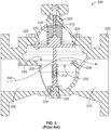
- FIG. 2 is a partial cutaway view of the known valve 200 in an open configuration.
- the valve 200 includes a valve body 202, a valve plug 204, a valve seat 206, a fluid inlet 208, a fluid outlet 210, a first stem 212, a second stem 214, a closing spring 216, and a fusible element 218.
- the valve plug 204 has a disc-shaped configuration, including a first surface 220 and a second surface 222 opposite the first surface 220.
- the first stem 212 is integral with and/or rigidly coupled to the first surface 220 of the valve plug 204 and positioned in a first bore 224 of the valve body 202.
- the second stem 214 is integral with and/or rigidly coupled to the second surface 222 of the valve plug 204 and positioned in a second bore 226 of the valve body 202.
- the valve seat 206 has a cylindrical configuration, including a first annular surface 228, a second annular surface 230 opposite the first annular surface 228, and an inner surface (not shown) between the first and second annular surfaces 228, 230.
- the first annular surface 228, second annular surface 230 and inner surface of the valve seat 206 collectively define an orifice 232.
- the valve seat 206 is rigidly coupled (e.g., via a press fit) to the valve body 202 at a position within the valve body 202 such that the valve plug 204 does not contact the valve seat 206 when the valve 200 is in an open configuration, as shown in FIG. 2 .
- a fluid may flow from the fluid inlet 208 toward the valve seat 206, through the orifice 232 defined by the valve seat 206 toward the fluid outlet 210, as is generally shown by the illustrated pathway 234.
- the closing spring 216 applies a force against the first surface 220 of the valve plug 204, thereby biasing the valve plug 204 toward the valve seat 206. More specifically, the closing spring 216 biases the second surface 222 of the valve plug 204 toward the first annular surface 228 of the valve seat 206.
- the fusible element 218 shown in FIG. 2 is positioned within the second bore 226 of the valve body 202 and is in contact with the second stem 214 commonly positioned therein.
- the fusible element 218 is configured to be of a shape, rigidity and/or hardness so as not to be deformed in response to the force applied by the closing spring 216 on the valve plug 204 and transmitted to the fusible element 218 via the second stem 214.
- the fusible element 218 maintains the valve plug 204 in an open and/or spaced apart position relative to the valve seat 206.
- FIG. 3 is a partial cutaway view of the known valve of FIG. 2 in a closed configuration.
- the fusible element 218 (or a substantial portion thereof) that appeared in FIG. 2 has melted away and/or been burned off as a result of exposure to of a high temperature (e.g., that which would be caused by a flame) within the valve body 202 of the valve 200.
- a high temperature e.g., that which would be caused by a flame
- the closing spring 216 causes a portion of the second surface 222 of the valve plug 204 to come into contact with a portion of the first annular surface 228 of the valve seat 206, thereby resulting in a metal-to-metal seal between the second surface 222 of the valve plug 204 and the first annular surface 228 of the valve seat 206.
- the respective geometries of the second surface 222 of the valve plug 204 and the first annular surface 228 of the valve seat 206 are flat and/or planar (e.g., not curved).
- the metal-to-metal seal that exists between the second surface 222 of the valve plug 204 and the first annular surface 228 of the valve seat 206 is intended to prevent a fluid from traveling along the pathway 234 shown in FIG. 2 , and to instead restrict the fluid to a location between the fluid inlet 208 and the valve seat 206, as is generally shown in FIG. 3 by the illustrated pathway 302.
- the adequacy of the illustrated metal-to-metal seal depends on the contacting portions of the second surface 222 of the valve plug 204 and the first annular surface 228 of the valve seat 206 being sufficiently flat and planar relative to one another, and further depends on the lateral alignment of the valve plug 204 relative to the valve seat 206 as provided for by the first and second stems 212, 214 positioned within the first and second bores 224, 226 of the valve body 202.
- the example valve 400 of FIGS. 4-7 includes an example valve plug 402 and an example valve seat 404 having respective example metallic sealing surfaces 406, 408 with complimentary curved profiles.
- the example valve 400 of FIGS. 4-7 is described below in the context of a thermal valve application, the example valve plug 402 and the example valve seat 404 of the example valve 400 may be implemented in any valve application requiring a metal-to-metal seal.
- the example valve 400 is shown in an open configuration.
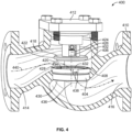
- the valve 400 includes the valve plug 402, the valve seat 404, an example valve body 410, an example bonnet 412, an example fluid inlet 414, an example fluid outlet 416, an example stem 502, an example stem guide 504, an example spring seat 506, an example spring seat guide 508, an example closing spring 510, and an example fusible link 512.
- the valve plug 402 has a disc-shaped configuration defined by an example first surface 418, an example second surface 420 opposite the first surface 418, and an example peripheral edge 422 located between the first and second surfaces 418, 420.
- the peripheral edge 422 of the valve plug 402 forms a circular profile that defines an example first central axis 424 of the valve plug 402.
- the profile of the valve plug 402 may alternatively take the form of other shapes and/or configurations including, for example, an oval, an ellipse, and/or any type of polygon (e.g., a triangle, rectangle, square, rhombus, pentagon, hexagon, octagon, etc.).
- the first metallic sealing surface 406 of the valve plug 402 extends circumferentially about the peripheral edge 422 of the valve plug 402. In the illustrated example, the first metallic sealing surface 406 is adjacent the second surface 420 of the valve plug 402. In the illustrated example, the first metallic sealing surface 406 is also adjacent the peripheral edge 422 of the valve plug 402. In some examples, the first metallic sealing surface 406 of the valve plug 402 has magnetic properties. In the illustrated example, the first metallic sealing surface 406 of the example valve plug 402 has an example first curved profile, which may be a concave parabolic shape. The first curved profile of the first metallic sealing surface 406 may alternatively take the form of other curved shapes, configurations, and/or orientations including, for example, a circular, convex, and/or s-shaped configuration.
- valve plug 402 also includes an example hub 426 located along the first surface 418 of the valve plug 402.
- the hub 426 contains a bore 514 that is configured to couple the valve plug 402 to the stem 502 via, for example, a threaded connection.
- the valve plug 402 may also include bores (not shown) through which the valve plug 402 may be coupled via suitable fasteners (e.g., bolts or screws) to the spring seat 506.
- the valve seat 404 has a cylindrical configuration, including an example first annular surface 428, an example second annular surface 430 opposite the first annular surface 428, and an example inner surface 432 located between the first and second annular surfaces 428, 430.
- the first annular surface 428, the second annular surface 430 and the inner surface 432 of the valve seat 404 collectively define an example orifice 434.
- the inner surface 432 of the valve seat 404 forms a circular profile that defines an example second central axis 436 of the valve seat 404.
- valve seat 404 has a circular profile
- profile of the valve seat 404 may alternatively take the form of other shapes and/or configurations including, for example, an oval, an ellipse, and/or any type of polygon (e.g., a triangle, rectangle, square, rhombus, pentagon, hexagon, octagon, etc.).
- the second metallic sealing surface 408 of the valve seat 404 extends circumferentially about the inner surface 432 of the valve seat 404.
- the second metallic sealing surface 408 is adjacent the first annular surface 428 of the valve seat 404.
- the second metallic sealing surface 408 is also adjacent the inner surface 432 of the valve seat 404.
- the second metallic sealing surface 408 of the valve plug 404 has magnetic properties, such that the first metallic sealing surface 406 of the valve plug 402 (which may also have magnetic properties) and the second metallic sealing surface 408 of the valve seat 404 are magnetically coupled when the first and second metallic sealing surfaces 406, 408 are in contact.
- the second metallic sealing surface 408 of the valve seat 404 has an example second curved profile.
- the second curved profile of the second metallic sealing surface 408 is complimentary to (e.g., having a radius of curvature that matches and/or is substantially the same as that of) the first curved profile of the first metallic sealing surface 406.
- the second curved profile has a convex parabolic shape.
- the second curved profile of the second metallic sealing surface 408 may alternatively take the form of any other curved shape, configuration, and/or orientation including, for example, a circular, concave, and/or s-shaped configuration having a curved profile that is complimentary to the first curved profile of the first metallic sealing surface 406.
- valve seat 404 is rigidly coupled (e.g., via a press fit) to the valve body 410 at a position within the valve body 410 such that the valve plug 402 does not contact the valve seat 404 when the valve 400 is in an open configuration, as shown in FIGS. 4-5 .
- the valve seat 404 includes example recesses 438 located along the first annular surface 428 of the valve seat 404 that may be used to facilitate the installation of the valve seat 404 within the valve body 410.
- a fluid may flow from the fluid inlet 414 toward the valve seat 404, through the orifice 434 defined by the valve seat 404 toward the fluid outlet 416, as is generally shown in FIG. 4 by the illustrated pathway 440.
- valve plug 402 is rigidly coupled to the stem 502, and the stem 502 is positioned within the stem guide 504, which is rigidly coupled (e.g., via a press fit) to the bonnet 412.
- the bonnet 412 is rigidly coupled via suitable fasteners (e.g., bolts or screws) to the valve body 410.
- the fusible link 512 rigidly couples the stem 502 to the stem guide 504 and prevents the stem 502 (and the attached valve plug 402) from translating within the stem guide 504 in a direction away from the bonnet 412 and toward the valve seat 404.
- valve plug 402 is also rigidly coupled to the spring seat 506.
- the spring seat 506 is positioned within the spring seat guide 508, which is rigidly coupled via suitable fasteners (e.g., bolts or screws) to the bonnet 412.
- the closing spring 510 is positioned within the spring seat 506.
- the closing spring 510 applies a force against the spring seat 506, thereby biasing the spring seat 506 and the attached valve plug 402 toward the valve seat 404. More specifically, the closing spring 510 biases the first metallic sealing surface 406 of the valve plug 402 toward the second metallic sealing surface 408 of the valve seat 404.
- the force applied by the closing spring 510 on the spring seat 506 is translated via the spring seat 506, the attached valve plug 402 and the attached stem 502 to the fusible link 512 that rigidly secures the stem 502 to the stem guide 504.
- the fusible link 512 is configured to be of a shape, rigidity and/or hardness so as not to be deformed in response to the force applied by the closing spring 510.
- the fusible link 512 maintains the example valve plug 402 in an open and/or spaced apart position relative to the valve seat 404.
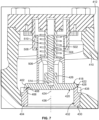
- FIGS. 6-7 the example valve 400 of FIGS. 4-5 is shown in a closed configuration.
- the fusible link 512 (or a substantial portion thereof) that appeared in FIG. 5 has melted away and/or been burned off as a result of exposure to a high temperature (e.g., that which would be caused by a flame) within the valve body 410 of the valve 400.
- a high temperature e.g., that which would be caused by a flame
- the closing spring 506 causes the first metallic sealing surface 406 of the valve plug 402 to come into contact with the complimentary second metallic sealing surface 408 of the valve seat 404, thereby resulting in a metal-to-metal seal between the first metallic sealing surface 406 of the valve plug 402 and the second metallic sealing surface 408 of the valve seat 404.
- the respective complimentary curved profiles of the first and second metallic sealing surfaces 406, 408 cause the first central axis 424 of the valve plug 402 to align with the second central axis 436 of the valve seat 404 when the first and second metallic sealing surfaces 406, 408 are in contact.
- the respective complimentary curved profiles of the first and second metallic sealing surfaces 406, 408 cause the valve plug 402 to be self-centering relative to the valve seat 404 when the valve plug 402 and the valve seat 404 are in a closed configuration.
- the metal-to-metal seal that exists between the first metallic sealing surface 406 of the valve plug 402 and the second metallic sealing surface 408 of the valve seat 404 prevents fluid from traveling along the pathway 440 shown in FIG. 4 , and instead restricts the fluid to a location between the fluid inlet 414 and the valve plug 402 and/or the valve seat 404, as is generally shown in FIG. 6 by the illustrated pathway 602.
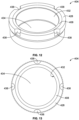
- FIGS. 8-11 illustrate the example valve plug 402 of FIGS. 4-7 in greater detail.
- the first metallic sealing surface 406 of the valve plug 402 extends circumferentially about the peripheral edge 422 of the valve plug 402.
- the first metallic sealing surface 406 is adjacent the second surface 420 of the valve plug 402, and is also adjacent the peripheral edge 422 of the valve plug 402.
- the first curved profile of the metallic sealing surface 406 has a concave parabolic shape.
- the hub 426 of the valve plug 402 includes the bore 514, which is configured to couple the valve plug 402 to the stem 502 described above in connection with FIGS. 4-7 via, for example, a threaded connection.
- the valve plug 402 also includes example bores 802 through which the valve plug 402 may be coupled via suitable fasteners (e.g., bolts or screws) to the spring seat 506 described above in connection with FIGS. 4-7 .
- FIGS. 12-15 illustrate the example valve seat 404 of FIGS. 4-7 in greater detail.
- the second metallic sealing surface 408 extends circumferentially about the inner surface 432 of the valve seat 404.
- the second metallic sealing surface 408 is adjacent the first annular surface 428 of the valve seat 404, and is also adjacent the inner surface 432 of the valve seat 404.
- the second curved profile of the second metallic sealing surface 408 has a convex parabolic shape that is complimentary to (e.g., having a radius of curvature that matches and/or is substantially the same as that of) the concave parabolic shape of the first curved profile of the first metallic sealing surface 406.
- the valve seat 404 includes the recesses 438 located along the first annular surface 428 of the valve seat 404 that may be used to facilitate the installation of the valve seat 404 within the valve body 410 described above in connection with FIGS. 4-7 .
- the respective complimentary curved profiles of the first and second metallic sealing surfaces 406, 408 described above in connection with FIGS. 8-15 cause the first central axis 424 of the valve plug 402 to align with the second central axis 436 of the valve seat 404 when the first and second metallic sealing surfaces 406, 408 are in contact.
- the respective complimentary curved profiles of the first and second metallic sealing surfaces 406, 408 cause the valve plug 402 to be self-centering relative to the valve seat 404 when the valve plug 402 and the valve seat 404 are in a closed configuration.
- the respective curved profiles of the first and second metallic sealing surfaces 406, 408 may be reversed and/or otherwise modified relative to the valve plug 402 and the valve seat 404 illustrated in FIGS. 8-15 .
- first metallic sealing surface 406 of the valve plug 402 may have a convex shape that is complimentary to a corresponding concave shape of the second metallic sealing surface 408 of the valve seat 404.
- the first and second metallic sealing surfaces 406, 408 may be of any shape, configuration and/or orientation so long as the first and second sealing surfaces 406, 408 have complimentary curved profiles.
Landscapes
- Engineering & Computer Science (AREA)
- General Engineering & Computer Science (AREA)
- Mechanical Engineering (AREA)
- Lift Valve (AREA)
Description
- This disclosure relates generally to metal-to-metal seals and, more particularly, to self-centering metal-to-metal seals for use with valves.
- Certain valve applications may require the mating of metallic sealing surfaces between a valve plug and a valve seat. For example, the mating of an elastomeric sealing surface to a metallic sealing surface, or to another elastomeric sealing surface, may not be suitable for valve applications that experience high temperatures and/or flames, such as may be experienced in a thermal valve.
- Current metal-to-metal seals implement a knife edge and disc type geometry in relation to the valve plug and the valve seat. This geometry often demonstrates a minimal sealing surface area that requires extensive polishing to provide an adequate metal-to-metal seal between the valve plug and the valve seat. This geometry is also susceptible to leakage due to scarring of the minimal sealing surface area.
- An apparatus according to the preamble of independent claim 1 is known from
US 2014/284509 A1 ,US 7 540 470 B andUS 4 262 698 A . - An example apparatus for use with a valve includes a disc-shaped valve plug having a first metallic sealing surface extending circumferentially about a peripheral edge of the valve plug. The first metallic sealing surface has a first curved profile. The example apparatus further includes a valve seat defining an orifice and having a second metallic sealing surface having a second curved profile that is complimentary to the first curved profile so that the first and second metallic sealing surfaces form a seal when the first and second metallic sealing surfaces are in contact.
-
-
FIG. 1 illustrates a system in which a valve having a metal-to-metal seal between a valve plug and a valve seat may be used. -
FIG. 2 is a partial cutaway view of a known valve in an open configuration. -
FIG. 3 is a partial cutaway view of the known valve ofFIG. 2 in a closed configuration. -
FIG. 4 is a partial cutaway view of an example valve having an example valve plug and an example valve seat including respective example metallic sealing surfaces having example complimentary curved profiles. The example valve ofFIG. 4 is in an open configuration. -
FIG. 5 is another partial cutaway view of the example valve ofFIG. 4 in an open configuration. -
FIG. 6 is a partial cutaway view of the example valve ofFIG. 4 in a closed configuration. -
FIG. 7 is another partial cutaway view of the example valve ofFIG. 4 in a closed configuration. -
FIG. 8 is a perspective view of the example valve plug shown inFIGS. 4-7 . -
FIG. 9 is a plan view of the example valve plug ofFIG. 8 . -
FIG. 10 is a side view of the example valve plug ofFIGS. 8-9 . -
FIG. 11 is a cross-sectional view of the example valve plug ofFIGS. 8-10 taken along line A-A ofFIG. 10 . -
FIG. 12 is a perspective view of the example valve seat shown inFIGS. 4-7 . -
FIG. 13 is a plan view of the example valve seat ofFIG. 12 . -
FIG. 14 is a side view of the example valve seat ofFIGS. 12-13 . -
FIG. 15 is a cross-sectional view of the example valve seat ofFIGS. 12-14 taken along line A-A ofFIG. 14 . - Certain examples are shown in the above-identified figures and described in detail below. In describing these examples, like or identical reference numbers are used to identify the same or similar elements. The figures are not necessarily to scale and certain features and certain views of the figures may be shown exaggerated in scale or in schematic for clarity and/or conciseness.
- The example apparatus described herein provides a self-centering metal-to-metal seal for use in valve applications. Unlike current metal-to-metal seals that implement a knife edge and disc type geometry in relation to the valve plug and the valve seat, the example apparatus described herein includes a valve plug and a valve seat having respective metallic sealing surfaces including complimentary curved profiles. The complimentary curved profiles increase the surface area of the resultant metal-to-metal seal and provide for a metal-to-metal seal that is self-centering. The increased surface area of the disclosed metal-to-metal seal requires less polishing relative to known metal-to-metal seal geometries, and the self-centering function of the disclosed metal-to-metal seal reduces the need for robust guidance structures between the valve plug and the valve seat.
- In some disclosed examples, the apparatus includes a disc-shaped valve plug having a first metallic sealing surface extending circumferentially about a peripheral edge of the valve plug. In such disclosed examples, the first metallic sealing surface has a first curved profile. In such disclosed examples, the apparatus further includes a valve seat defining an orifice and having a second metallic sealing surface having a second curved profile that is complimentary to the first curved profile so that the first and second metallic sealing surfaces form a seal when the first and second metallic sealing surfaces are in contact.
- In some disclosed examples, the first and second curved profiles of the first and second metallic sealing surfaces have radii of curvature that match and/or are substantially the same. In some disclosed examples, the first and second curved profiles of the first and second sealing surfaces are parabolic in shape. In some disclosed examples, the first curved profile of the first metallic sealing surface has a concave shape, and the second curved profile of the second metallic sealing surface has a convex shape.
- In some disclosed examples, the valve plug includes a first surface and a second surface opposite the first surface, with the peripheral edge of the valve plug being between the first and second surfaces of the valve plug. In some disclosed examples, the first metallic sealing surface is adjacent the second surface of the valve plug. In some disclosed examples, the first metallic sealing surface is adjacent the peripheral edge of the valve plug.
- In some disclosed examples, the valve seat includes a first annular surface and a second annular surface opposite the first annular surface, and an inner surface between the first and second annular surfaces of the valve seat. In some disclosed examples, the second metallic sealing surface is adjacent the first surface of the valve seat. In some disclosed examples, the second metallic sealing surface is adjacent the inner surface of the valve seat.
- In some disclosed examples, the valve plug has a first central axis defined by the peripheral edge of the valve plug, the valve seat has a second central axis defined by the inner surface of the valve seat, and the first and second metallic sealing surfaces align the first central axis with the second central axis when the first and second metallic sealing surfaces are in contact. In some disclosed examples, the first and second metallic sealing surfaces are magnetically coupled when the first and second metallic sealing surfaces are in contact.
-
FIG. 1 illustrates asystem 100 in which a valve having a metal-to-metal seal between a valve plug and a valve seat may be used. In thesystem 100 ofFIG. 1 , the valve is athermal valve 102. In operation, fluid (e.g., vapor) flows from astorage tank 104 through afirst conduit 106 to anarrestor 108. The fluid flows through thearrestor 108, through thethermal valve 102, and through asecond conduit 110 to the atmosphere. Aflare 112 burns off excess vapor associated with the fluid. - In the illustrated
system 100 ofFIG. 1 , a flame associated with theflare 112 may attempt to travel back through the second andfirst conduits storage tank 104. Thearrestor 108 is designed to prevent the propagation of the flame toward thestorage tank 104. However, if a stabilized flame forms in thearrestor 108 and goes undetected, thearrestor 108 may overheat and allow the flame to pass through to thestorage tank 104. However, in the illustratedsystem 100, thethermal valve 102 prevents thearrestor 108 from overheating. Thethermal valve 102 is designed to sense the stabilized flame and to close and/or shut (e.g., to seal off the continued flow of the fluid to the atmosphere), thereby extinguishing the flame and eliminating the risk of thearrestor 108 overheating. Thethermal valve 102 may include a metallic valve plug (not shown) and a metallic valve seat (not shown) that provide a metal-to-metal seal when thethermal valve 102 is in a closed and/or shut position such as, for example, when the valve plug and the valve seat are in contact. - Before describing the details of the example valve having a valve plug and a valve seat including respective metallic sealing surfaces having complimentary curved profiles, a description of a known
valve 200 is provided in connection withFIGS. 2 and3 . -
FIG. 2 is a partial cutaway view of the knownvalve 200 in an open configuration. Thevalve 200 includes avalve body 202, avalve plug 204, avalve seat 206, afluid inlet 208, afluid outlet 210, afirst stem 212, asecond stem 214, aclosing spring 216, and afusible element 218. Thevalve plug 204 has a disc-shaped configuration, including afirst surface 220 and asecond surface 222 opposite thefirst surface 220. Thefirst stem 212 is integral with and/or rigidly coupled to thefirst surface 220 of thevalve plug 204 and positioned in afirst bore 224 of thevalve body 202. Thesecond stem 214 is integral with and/or rigidly coupled to thesecond surface 222 of thevalve plug 204 and positioned in asecond bore 226 of thevalve body 202. - The
valve seat 206 has a cylindrical configuration, including a firstannular surface 228, a secondannular surface 230 opposite the firstannular surface 228, and an inner surface (not shown) between the first and secondannular surfaces annular surface 228, secondannular surface 230 and inner surface of thevalve seat 206 collectively define anorifice 232. Thevalve seat 206 is rigidly coupled (e.g., via a press fit) to thevalve body 202 at a position within thevalve body 202 such that thevalve plug 204 does not contact thevalve seat 206 when thevalve 200 is in an open configuration, as shown inFIG. 2 . When thevalve 200 is in an open configuration, a fluid may flow from thefluid inlet 208 toward thevalve seat 206, through theorifice 232 defined by thevalve seat 206 toward thefluid outlet 210, as is generally shown by the illustratedpathway 234. - The
closing spring 216 applies a force against thefirst surface 220 of thevalve plug 204, thereby biasing thevalve plug 204 toward thevalve seat 206. More specifically, theclosing spring 216 biases thesecond surface 222 of thevalve plug 204 toward the firstannular surface 228 of thevalve seat 206. Thefusible element 218 shown inFIG. 2 is positioned within thesecond bore 226 of thevalve body 202 and is in contact with thesecond stem 214 commonly positioned therein. Thefusible element 218 is configured to be of a shape, rigidity and/or hardness so as not to be deformed in response to the force applied by theclosing spring 216 on thevalve plug 204 and transmitted to thefusible element 218 via thesecond stem 214. Thus, under normal operating conditions, thefusible element 218 maintains thevalve plug 204 in an open and/or spaced apart position relative to thevalve seat 206. -
FIG. 3 is a partial cutaway view of the known valve ofFIG. 2 in a closed configuration. InFIG. 3 , the fusible element 218 (or a substantial portion thereof) that appeared inFIG. 2 has melted away and/or been burned off as a result of exposure to of a high temperature (e.g., that which would be caused by a flame) within thevalve body 202 of thevalve 200. In the absence of thefusible element 218, the force applied by theclosing spring 216 against thefirst surface 220 of thevalve plug 204 causes thevalve plug 204 to come into contact with thevalve seat 206. More specifically, theclosing spring 216 causes a portion of thesecond surface 222 of thevalve plug 204 to come into contact with a portion of the firstannular surface 228 of thevalve seat 206, thereby resulting in a metal-to-metal seal between thesecond surface 222 of thevalve plug 204 and the firstannular surface 228 of thevalve seat 206. - As shown in
FIGS. 2 and3 , the respective geometries of thesecond surface 222 of thevalve plug 204 and the firstannular surface 228 of thevalve seat 206 are flat and/or planar (e.g., not curved). When thevalve 200 is in a closed configuration as described above in connection withFIG. 3 , the metal-to-metal seal that exists between thesecond surface 222 of thevalve plug 204 and the firstannular surface 228 of thevalve seat 206 is intended to prevent a fluid from traveling along thepathway 234 shown inFIG. 2 , and to instead restrict the fluid to a location between thefluid inlet 208 and thevalve seat 206, as is generally shown inFIG. 3 by the illustratedpathway 302. The adequacy of the illustrated metal-to-metal seal depends on the contacting portions of thesecond surface 222 of thevalve plug 204 and the firstannular surface 228 of thevalve seat 206 being sufficiently flat and planar relative to one another, and further depends on the lateral alignment of thevalve plug 204 relative to thevalve seat 206 as provided for by the first and second stems 212, 214 positioned within the first andsecond bores valve body 202. - In contrast to the known
valve 200 described above in connection withFIGS. 2 and3 , theexample valve 400 ofFIGS. 4-7 includes anexample valve plug 402 and anexample valve seat 404 having respective example metallic sealing surfaces 406, 408 with complimentary curved profiles. Although theexample valve 400 ofFIGS. 4-7 is described below in the context of a thermal valve application, theexample valve plug 402 and theexample valve seat 404 of theexample valve 400 may be implemented in any valve application requiring a metal-to-metal seal. - Referring to
FIGS. 4-5 , theexample valve 400 is shown in an open configuration. Thevalve 400 includes thevalve plug 402, thevalve seat 404, anexample valve body 410, anexample bonnet 412, anexample fluid inlet 414, anexample fluid outlet 416, anexample stem 502, anexample stem guide 504, anexample spring seat 506, an examplespring seat guide 508, anexample closing spring 510, and an examplefusible link 512. - In the illustrated example, the
valve plug 402 has a disc-shaped configuration defined by an examplefirst surface 418, an examplesecond surface 420 opposite thefirst surface 418, and an exampleperipheral edge 422 located between the first andsecond surfaces peripheral edge 422 of thevalve plug 402 forms a circular profile that defines an example firstcentral axis 424 of thevalve plug 402. Although the illustratedvalve plug 402 has a circular profile, the profile of thevalve plug 402 may alternatively take the form of other shapes and/or configurations including, for example, an oval, an ellipse, and/or any type of polygon (e.g., a triangle, rectangle, square, rhombus, pentagon, hexagon, octagon, etc.). - In the illustrated example, the first
metallic sealing surface 406 of thevalve plug 402 extends circumferentially about theperipheral edge 422 of thevalve plug 402. In the illustrated example, the firstmetallic sealing surface 406 is adjacent thesecond surface 420 of thevalve plug 402. In the illustrated example, the firstmetallic sealing surface 406 is also adjacent theperipheral edge 422 of thevalve plug 402. In some examples, the firstmetallic sealing surface 406 of thevalve plug 402 has magnetic properties. In the illustrated example, the firstmetallic sealing surface 406 of theexample valve plug 402 has an example first curved profile, which may be a concave parabolic shape. The first curved profile of the firstmetallic sealing surface 406 may alternatively take the form of other curved shapes, configurations, and/or orientations including, for example, a circular, convex, and/or s-shaped configuration. - In the illustrated example, the
valve plug 402 also includes anexample hub 426 located along thefirst surface 418 of thevalve plug 402. Thehub 426 contains abore 514 that is configured to couple thevalve plug 402 to thestem 502 via, for example, a threaded connection. Thevalve plug 402 may also include bores (not shown) through which thevalve plug 402 may be coupled via suitable fasteners (e.g., bolts or screws) to thespring seat 506. - In the illustrated example, the
valve seat 404 has a cylindrical configuration, including an example firstannular surface 428, an example secondannular surface 430 opposite the firstannular surface 428, and an exampleinner surface 432 located between the first and secondannular surfaces annular surface 428, the secondannular surface 430 and theinner surface 432 of thevalve seat 404 collectively define anexample orifice 434. In the illustrated example, theinner surface 432 of thevalve seat 404 forms a circular profile that defines an example secondcentral axis 436 of thevalve seat 404. Although the illustratedvalve seat 404 has a circular profile, the profile of thevalve seat 404 may alternatively take the form of other shapes and/or configurations including, for example, an oval, an ellipse, and/or any type of polygon (e.g., a triangle, rectangle, square, rhombus, pentagon, hexagon, octagon, etc.). - In the illustrated example, the second metallic sealing
surface 408 of thevalve seat 404 extends circumferentially about theinner surface 432 of thevalve seat 404. In the illustrated example, the second metallic sealingsurface 408 is adjacent the firstannular surface 428 of thevalve seat 404. In the illustrated example, the second metallic sealingsurface 408 is also adjacent theinner surface 432 of thevalve seat 404. In some examples, the second metallic sealingsurface 408 of thevalve plug 404 has magnetic properties, such that the firstmetallic sealing surface 406 of the valve plug 402 (which may also have magnetic properties) and the second metallic sealingsurface 408 of thevalve seat 404 are magnetically coupled when the first and second metallic sealingsurfaces - In the illustrated example, the second metallic sealing
surface 408 of thevalve seat 404 has an example second curved profile. In the illustrated example, the second curved profile of the second metallic sealingsurface 408 is complimentary to (e.g., having a radius of curvature that matches and/or is substantially the same as that of) the first curved profile of the firstmetallic sealing surface 406. In the illustrated example, the second curved profile has a convex parabolic shape. The second curved profile of the second metallic sealingsurface 408 may alternatively take the form of any other curved shape, configuration, and/or orientation including, for example, a circular, concave, and/or s-shaped configuration having a curved profile that is complimentary to the first curved profile of the firstmetallic sealing surface 406. - In the illustrated example, the
valve seat 404 is rigidly coupled (e.g., via a press fit) to thevalve body 410 at a position within thevalve body 410 such that thevalve plug 402 does not contact thevalve seat 404 when thevalve 400 is in an open configuration, as shown inFIGS. 4-5 . In the illustrated example, thevalve seat 404 includes example recesses 438 located along the firstannular surface 428 of thevalve seat 404 that may be used to facilitate the installation of thevalve seat 404 within thevalve body 410. When thevalve 400 is in an open configuration, a fluid may flow from thefluid inlet 414 toward thevalve seat 404, through theorifice 434 defined by thevalve seat 404 toward thefluid outlet 416, as is generally shown inFIG. 4 by the illustratedpathway 440. - In the illustrated example, the
valve plug 402 is rigidly coupled to thestem 502, and thestem 502 is positioned within thestem guide 504, which is rigidly coupled (e.g., via a press fit) to thebonnet 412. Thebonnet 412 is rigidly coupled via suitable fasteners (e.g., bolts or screws) to thevalve body 410. In the illustrated example, thefusible link 512 rigidly couples thestem 502 to thestem guide 504 and prevents the stem 502 (and the attached valve plug 402) from translating within thestem guide 504 in a direction away from thebonnet 412 and toward thevalve seat 404. - In the illustrated example, the
valve plug 402 is also rigidly coupled to thespring seat 506. In the illustrated example, thespring seat 506 is positioned within thespring seat guide 508, which is rigidly coupled via suitable fasteners (e.g., bolts or screws) to thebonnet 412. Theclosing spring 510 is positioned within thespring seat 506. In the illustrated example, theclosing spring 510 applies a force against thespring seat 506, thereby biasing thespring seat 506 and the attachedvalve plug 402 toward thevalve seat 404. More specifically, theclosing spring 510 biases the firstmetallic sealing surface 406 of thevalve plug 402 toward the second metallic sealingsurface 408 of thevalve seat 404. In the illustrated example, the force applied by theclosing spring 510 on thespring seat 506 is translated via thespring seat 506, the attachedvalve plug 402 and the attachedstem 502 to thefusible link 512 that rigidly secures thestem 502 to thestem guide 504. Thefusible link 512 is configured to be of a shape, rigidity and/or hardness so as not to be deformed in response to the force applied by theclosing spring 510. Thus, thefusible link 512 maintains theexample valve plug 402 in an open and/or spaced apart position relative to thevalve seat 404. - Referring to
FIGS. 6-7 , theexample valve 400 ofFIGS. 4-5 is shown in a closed configuration. In the illustrated example ofFIGS. 6-7 , the fusible link 512 (or a substantial portion thereof) that appeared inFIG. 5 has melted away and/or been burned off as a result of exposure to a high temperature (e.g., that which would be caused by a flame) within thevalve body 410 of thevalve 400. In the absence of thefusible link 512, the force applied by theclosing spring 510 against thespring seat 506 causes thespring seat 506 and the attachedvalve plug 402 to come into contact with thevalve seat 404. More specifically, theclosing spring 506 causes the firstmetallic sealing surface 406 of thevalve plug 402 to come into contact with the complimentary second metallic sealingsurface 408 of thevalve seat 404, thereby resulting in a metal-to-metal seal between the firstmetallic sealing surface 406 of thevalve plug 402 and the second metallic sealingsurface 408 of thevalve seat 404. - As illustrated in
FIGS. 6-7 , the respective complimentary curved profiles of the first and second metallic sealingsurfaces central axis 424 of thevalve plug 402 to align with the secondcentral axis 436 of thevalve seat 404 when the first and second metallic sealingsurfaces surfaces valve plug 402 to be self-centering relative to thevalve seat 404 when thevalve plug 402 and thevalve seat 404 are in a closed configuration. When thevalve 400 is placed into a closed configuration as described above in connection withFIGS. 6-7 , the metal-to-metal seal that exists between the firstmetallic sealing surface 406 of thevalve plug 402 and the second metallic sealingsurface 408 of thevalve seat 404 prevents fluid from traveling along thepathway 440 shown inFIG. 4 , and instead restricts the fluid to a location between thefluid inlet 414 and thevalve plug 402 and/or thevalve seat 404, as is generally shown inFIG. 6 by the illustratedpathway 602. -
FIGS. 8-11 illustrate theexample valve plug 402 ofFIGS. 4-7 in greater detail. As more clearly shown inFIGS. 8-11 , the firstmetallic sealing surface 406 of thevalve plug 402 extends circumferentially about theperipheral edge 422 of thevalve plug 402. The firstmetallic sealing surface 406 is adjacent thesecond surface 420 of thevalve plug 402, and is also adjacent theperipheral edge 422 of thevalve plug 402. The first curved profile of themetallic sealing surface 406 has a concave parabolic shape. As more clearly shown inFIGS. 8-11 , thehub 426 of thevalve plug 402 includes thebore 514, which is configured to couple thevalve plug 402 to thestem 502 described above in connection withFIGS. 4-7 via, for example, a threaded connection. Thevalve plug 402 also includes example bores 802 through which thevalve plug 402 may be coupled via suitable fasteners (e.g., bolts or screws) to thespring seat 506 described above in connection withFIGS. 4-7 . -
FIGS. 12-15 illustrate theexample valve seat 404 ofFIGS. 4-7 in greater detail. As more clearly shown inFIGS. 12-15 , the second metallic sealingsurface 408 extends circumferentially about theinner surface 432 of thevalve seat 404. The second metallic sealingsurface 408 is adjacent the firstannular surface 428 of thevalve seat 404, and is also adjacent theinner surface 432 of thevalve seat 404. The second curved profile of the second metallic sealingsurface 408 has a convex parabolic shape that is complimentary to (e.g., having a radius of curvature that matches and/or is substantially the same as that of) the concave parabolic shape of the first curved profile of the firstmetallic sealing surface 406. As more clearly shown inFIGS. 12-15 , thevalve seat 404 includes therecesses 438 located along the firstannular surface 428 of thevalve seat 404 that may be used to facilitate the installation of thevalve seat 404 within thevalve body 410 described above in connection withFIGS. 4-7 . - The respective complimentary curved profiles of the first and second metallic sealing
surfaces FIGS. 8-15 cause the firstcentral axis 424 of thevalve plug 402 to align with the secondcentral axis 436 of thevalve seat 404 when the first and second metallic sealingsurfaces surfaces valve plug 402 to be self-centering relative to thevalve seat 404 when thevalve plug 402 and thevalve seat 404 are in a closed configuration. In some examples, the respective curved profiles of the first and second metallic sealingsurfaces valve plug 402 and thevalve seat 404 illustrated inFIGS. 8-15 . For example, the firstmetallic sealing surface 406 of thevalve plug 402 may have a convex shape that is complimentary to a corresponding concave shape of the second metallic sealingsurface 408 of thevalve seat 404. The first and second metallic sealingsurfaces - Although certain apparatus have been described herein, the scope of coverage of this patent is not limited thereto. On the contrary, this patent covers all apparatus falling within the scope of the appended claims.
Claims (9)
- An apparatus, comprising:a disc-shaped valve plug (402) including a first metallic sealing surface (406) extending circumferentially about a peripheral edge (422) of the valve plug (402), the first metallic sealing surface (406) having a first curved profile; anda valve seat (404) defining an orifice (434) and including a second metallic sealing surface (408) having a second curved profile, the first and second profiles being complementary so that the first and second metallic sealing surfaces (406, 408) form a seal when the first and second metallic sealing surfaces (406, 408) are in contact; and characterized in that the apparatus comprises a spring seat (506) coupled to the valve plug (402) via suitable fasteners positioned within bores (802) of the valve plug (402).
- The apparatus as defined in claim 1, wherein the first and second curved profiles have respective parabolic shapes.
- The apparatus as defined in any of the preceding claims, wherein the first curved profile has a concave shape and the second curved profile has a convex shape.
- The apparatus as defined in any of the preceding claims, wherein the valve plug (402) includes a first surface (418) and a second surface (420) opposite the first surface (418), the peripheral edge (422) of the valve plug (402) being between the first and second surfaces (418, 420) of the valve plug (402), the first metallic sealing surface (406) being adjacent the second surface (420) of the valve plug (402).
- The apparatus as defined in any of the preceding claims, wherein the valve seat (404) includes a first annular surface (428) and a second annular surface (430) opposite the first annular surface (428), the second metallic sealing surface (408) being adjacent the first annular surface (428) of the valve seat (404).
- The apparatus as defined in any of the preceding claims, wherein the valve seat (404) includes an inner surface (432), the inner surface (432) being between the first and second annular surfaces (428, 430) of the valve seat (404), the second metallic sealing surface (408) being adjacent the inner surface (432) of the valve seat (404).
- The apparatus as defined in any of the preceding claims, wherein the valve plug (402) has a first central axis defined by the peripheral edge (422) of the valve plug (402), the valve seat (404) has a second central axis defined by an inner surface (432) of the valve seat (404), and wherein the first and second metallic sealing surfaces (406, 408) align the first central axis with the second central axis when the first and second metallic sealing surfaces (406, 408) are in contact.
- The apparatus as defined in any of the preceding claims, wherein the first and second metallic sealing surfaces (406, 408) are magnetically coupled when the first and second metallic sealing surfaces (406, 408) are in contact.
- The apparatus as defined in claim 1, further comprising:a valve body (410); anda bonnet (412) rigidly coupled to the valve body (410) via suitable fasteners,wherein the spring seat (506) is positioned within a spring seat guide (508) rigidly coupled to the bonnet (412) via said suitable fasteners.
Applications Claiming Priority (3)
| Application Number | Priority Date | Filing Date | Title |
|---|---|---|---|
| US201562210665P | 2015-08-27 | 2015-08-27 | |
| US15/056,476 US9732858B2 (en) | 2015-08-27 | 2016-02-29 | Self-centering metal-to-metal seals for use with valves |
| PCT/US2016/048962 WO2017035463A1 (en) | 2015-08-27 | 2016-08-26 | Self-centering metal-to-metal seals for use with valves |
Publications (2)
| Publication Number | Publication Date |
|---|---|
| EP3341634A1 EP3341634A1 (en) | 2018-07-04 |
| EP3341634B1 true EP3341634B1 (en) | 2023-09-27 |
Family
ID=58097718
Family Applications (1)
| Application Number | Title | Priority Date | Filing Date |
|---|---|---|---|
| EP16763399.9A Active EP3341634B1 (en) | 2015-08-27 | 2016-08-26 | Self-centering metal-to-metal seals for use with valves |
Country Status (5)
| Country | Link |
|---|---|
| US (1) | US9732858B2 (en) |
| EP (1) | EP3341634B1 (en) |
| CN (2) | CN206092981U (en) |
| MX (1) | MX2018002488A (en) |
| WO (1) | WO2017035463A1 (en) |
Families Citing this family (3)
| Publication number | Priority date | Publication date | Assignee | Title |
|---|---|---|---|---|
| US9732858B2 (en) * | 2015-08-27 | 2017-08-15 | Emerson Process Management Regulator Technologies Tulsa, Llc | Self-centering metal-to-metal seals for use with valves |
| DE102017215102A1 (en) * | 2017-08-30 | 2019-02-28 | Evoguard Gmbh | Steam trap and aseptic double-seat valve |
| DE102017221518A1 (en) * | 2017-11-30 | 2019-06-06 | Reinz-Dichtungs-Gmbh | Valve and method of manufacturing a valve |
Family Cites Families (14)
| Publication number | Priority date | Publication date | Assignee | Title |
|---|---|---|---|---|
| US1686849A (en) * | 1927-10-15 | 1928-10-09 | Aloysius M Frauenheim | Fluid valve |
| US1748169A (en) * | 1928-05-03 | 1930-02-25 | New York Air Brake Co | Valve |
| US2131928A (en) * | 1935-09-30 | 1938-10-04 | Baldwin Reinhold | Slush pump valve and the like |
| US2413869A (en) * | 1940-06-11 | 1947-01-07 | Falcon Products Inc | Valve |
| US2786485A (en) * | 1951-08-13 | 1957-03-26 | Lois Stcirly Rozzell | Slush pump valve |
| US3550903A (en) * | 1967-06-27 | 1970-12-29 | Huntington Mechanical Lab | Valve and valve closure mechanism |
| US3857542A (en) * | 1972-06-06 | 1974-12-31 | Westinghouse Electric Corp | Noise suppressing throttle valve |
| US4262698A (en) | 1979-12-26 | 1981-04-21 | Yardney Electric Corporation | Valve |
| DE3026133A1 (en) * | 1980-07-10 | 1982-02-18 | Robert Bosch Gmbh, 7000 Stuttgart | ELECTROMAGNETIC VALVE |
| EP1334300B1 (en) * | 2000-11-01 | 2016-09-07 | Elliott Company | High-stability valve arrangement for a governor valve |
| US7540470B1 (en) | 2005-01-11 | 2009-06-02 | Blume George H | Powdered metal inlay |
| CN202252200U (en) * | 2011-07-01 | 2012-05-30 | 艾默生过程管理调节技术公司 | Fluid adjusting device |
| JP5755555B2 (en) * | 2011-12-08 | 2015-07-29 | 株式会社東芝 | Valve device, method for manufacturing valve device, and method for repairing valve device |
| US9732858B2 (en) * | 2015-08-27 | 2017-08-15 | Emerson Process Management Regulator Technologies Tulsa, Llc | Self-centering metal-to-metal seals for use with valves |
-
2016
- 2016-02-29 US US15/056,476 patent/US9732858B2/en active Active
- 2016-08-26 CN CN201620962436.3U patent/CN206092981U/en active Active
- 2016-08-26 MX MX2018002488A patent/MX2018002488A/en unknown
- 2016-08-26 WO PCT/US2016/048962 patent/WO2017035463A1/en not_active Ceased
- 2016-08-26 EP EP16763399.9A patent/EP3341634B1/en active Active
- 2016-08-26 CN CN201610741306.1A patent/CN106481821B/en active Active
Also Published As
| Publication number | Publication date |
|---|---|
| WO2017035463A1 (en) | 2017-03-02 |
| EP3341634A1 (en) | 2018-07-04 |
| CN106481821A (en) | 2017-03-08 |
| US20170059043A1 (en) | 2017-03-02 |
| CN106481821B (en) | 2020-07-24 |
| CN206092981U (en) | 2017-04-12 |
| MX2018002488A (en) | 2019-04-04 |
| US9732858B2 (en) | 2017-08-15 |
Similar Documents
| Publication | Publication Date | Title |
|---|---|---|
| US4637421A (en) | In-line repairable top entry ball valve | |
| EP2454511B1 (en) | Seal assemblies for use with fluid valves | |
| EP2901050B1 (en) | Slam shut safety device with guided plug support | |
| EP0137842B1 (en) | Fire resistant gate valve | |
| US20180238459A1 (en) | Check Valve | |
| US9732858B2 (en) | Self-centering metal-to-metal seals for use with valves | |
| EP3658806B1 (en) | Seal assemblies for use with fluid valves | |
| KR20140002317A (en) | Ball valve | |
| EP3011207B1 (en) | Seal assemblies for use with fluid valves | |
| EP3658807A1 (en) | Fluid flow control apparatus for use with fluid valves | |
| EP0124234B1 (en) | Gate valve | |
| US9395019B2 (en) | Device for sealing a valve | |
| WO2019199534A1 (en) | Purge apparatus for use with fluid valves | |
| US10174855B2 (en) | Pin release thermal valve | |
| JP2007501369A (en) | Bushless stem guide control valve | |
| EP2901051B1 (en) | Slam shut safety device with guided valve disc | |
| US8430121B2 (en) | Gas flow monitor | |
| US10393278B2 (en) | Check valve | |
| US20180259083A1 (en) | Valve Body Having Primary and Secondary Stem Guides | |
| US8672290B2 (en) | Self aligning spherical backseat assembly for a valve | |
| RU2544677C1 (en) | Wedge gate valve | |
| CA1200174A (en) | Poppet check valve | |
| CN117043499A (en) | Improving safety valves for use at extremely high temperatures | |
| JPH0578712B2 (en) | ||
| GB2526765A (en) | Sealing Seat Arrangement |
Legal Events
| Date | Code | Title | Description |
|---|---|---|---|
| STAA | Information on the status of an ep patent application or granted ep patent |
Free format text: STATUS: THE INTERNATIONAL PUBLICATION HAS BEEN MADE |
|
| PUAI | Public reference made under article 153(3) epc to a published international application that has entered the european phase |
Free format text: ORIGINAL CODE: 0009012 |
|
| STAA | Information on the status of an ep patent application or granted ep patent |
Free format text: STATUS: REQUEST FOR EXAMINATION WAS MADE |
|
| 17P | Request for examination filed |
Effective date: 20180209 |
|
| AK | Designated contracting states |
Kind code of ref document: A1 Designated state(s): AL AT BE BG CH CY CZ DE DK EE ES FI FR GB GR HR HU IE IS IT LI LT LU LV MC MK MT NL NO PL PT RO RS SE SI SK SM TR |
|
| AX | Request for extension of the european patent |
Extension state: BA ME |
|
| DAV | Request for validation of the european patent (deleted) | ||
| DAX | Request for extension of the european patent (deleted) | ||
| STAA | Information on the status of an ep patent application or granted ep patent |
Free format text: STATUS: EXAMINATION IS IN PROGRESS |
|
| 17Q | First examination report despatched |
Effective date: 20210209 |
|
| GRAP | Despatch of communication of intention to grant a patent |
Free format text: ORIGINAL CODE: EPIDOSNIGR1 |
|
| STAA | Information on the status of an ep patent application or granted ep patent |
Free format text: STATUS: GRANT OF PATENT IS INTENDED |
|
| INTG | Intention to grant announced |
Effective date: 20230329 |
|
| GRAS | Grant fee paid |
Free format text: ORIGINAL CODE: EPIDOSNIGR3 |
|
| GRAA | (expected) grant |
Free format text: ORIGINAL CODE: 0009210 |
|
| STAA | Information on the status of an ep patent application or granted ep patent |
Free format text: STATUS: THE PATENT HAS BEEN GRANTED |
|
| AK | Designated contracting states |
Kind code of ref document: B1 Designated state(s): AL AT BE BG CH CY CZ DE DK EE ES FI FR GB GR HR HU IE IS IT LI LT LU LV MC MK MT NL NO PL PT RO RS SE SI SK SM TR |
|
| REG | Reference to a national code |
Ref country code: GB Ref legal event code: FG4D |
|
| REG | Reference to a national code |
Ref country code: CH Ref legal event code: EP |
|
| REG | Reference to a national code |
Ref country code: DE Ref legal event code: R096 Ref document number: 602016083031 Country of ref document: DE |
|
| REG | Reference to a national code |
Ref country code: IE Ref legal event code: FG4D |
|
| REG | Reference to a national code |
Ref country code: LT Ref legal event code: MG9D |
|
| PG25 | Lapsed in a contracting state [announced via postgrant information from national office to epo] |
Ref country code: GR Free format text: LAPSE BECAUSE OF FAILURE TO SUBMIT A TRANSLATION OF THE DESCRIPTION OR TO PAY THE FEE WITHIN THE PRESCRIBED TIME-LIMIT Effective date: 20231228 |
|
| PG25 | Lapsed in a contracting state [announced via postgrant information from national office to epo] |
Ref country code: SE Free format text: LAPSE BECAUSE OF FAILURE TO SUBMIT A TRANSLATION OF THE DESCRIPTION OR TO PAY THE FEE WITHIN THE PRESCRIBED TIME-LIMIT Effective date: 20230927 Ref country code: RS Free format text: LAPSE BECAUSE OF FAILURE TO SUBMIT A TRANSLATION OF THE DESCRIPTION OR TO PAY THE FEE WITHIN THE PRESCRIBED TIME-LIMIT Effective date: 20230927 Ref country code: NO Free format text: LAPSE BECAUSE OF FAILURE TO SUBMIT A TRANSLATION OF THE DESCRIPTION OR TO PAY THE FEE WITHIN THE PRESCRIBED TIME-LIMIT Effective date: 20231227 Ref country code: LV Free format text: LAPSE BECAUSE OF FAILURE TO SUBMIT A TRANSLATION OF THE DESCRIPTION OR TO PAY THE FEE WITHIN THE PRESCRIBED TIME-LIMIT Effective date: 20230927 Ref country code: LT Free format text: LAPSE BECAUSE OF FAILURE TO SUBMIT A TRANSLATION OF THE DESCRIPTION OR TO PAY THE FEE WITHIN THE PRESCRIBED TIME-LIMIT Effective date: 20230927 Ref country code: HR Free format text: LAPSE BECAUSE OF FAILURE TO SUBMIT A TRANSLATION OF THE DESCRIPTION OR TO PAY THE FEE WITHIN THE PRESCRIBED TIME-LIMIT Effective date: 20230927 Ref country code: GR Free format text: LAPSE BECAUSE OF FAILURE TO SUBMIT A TRANSLATION OF THE DESCRIPTION OR TO PAY THE FEE WITHIN THE PRESCRIBED TIME-LIMIT Effective date: 20231228 Ref country code: FI Free format text: LAPSE BECAUSE OF FAILURE TO SUBMIT A TRANSLATION OF THE DESCRIPTION OR TO PAY THE FEE WITHIN THE PRESCRIBED TIME-LIMIT Effective date: 20230927 |
|
| REG | Reference to a national code |
Ref country code: NL Ref legal event code: MP Effective date: 20230927 |
|
| REG | Reference to a national code |
Ref country code: AT Ref legal event code: MK05 Ref document number: 1615703 Country of ref document: AT Kind code of ref document: T Effective date: 20230927 |
|
| PG25 | Lapsed in a contracting state [announced via postgrant information from national office to epo] |
Ref country code: NL Free format text: LAPSE BECAUSE OF FAILURE TO SUBMIT A TRANSLATION OF THE DESCRIPTION OR TO PAY THE FEE WITHIN THE PRESCRIBED TIME-LIMIT Effective date: 20230927 |
|
| PG25 | Lapsed in a contracting state [announced via postgrant information from national office to epo] |
Ref country code: IS Free format text: LAPSE BECAUSE OF FAILURE TO SUBMIT A TRANSLATION OF THE DESCRIPTION OR TO PAY THE FEE WITHIN THE PRESCRIBED TIME-LIMIT Effective date: 20240127 |
|
| PG25 | Lapsed in a contracting state [announced via postgrant information from national office to epo] |
Ref country code: AT Free format text: LAPSE BECAUSE OF FAILURE TO SUBMIT A TRANSLATION OF THE DESCRIPTION OR TO PAY THE FEE WITHIN THE PRESCRIBED TIME-LIMIT Effective date: 20230927 |
|
| PG25 | Lapsed in a contracting state [announced via postgrant information from national office to epo] |
Ref country code: ES Free format text: LAPSE BECAUSE OF FAILURE TO SUBMIT A TRANSLATION OF THE DESCRIPTION OR TO PAY THE FEE WITHIN THE PRESCRIBED TIME-LIMIT Effective date: 20230927 |
|
| PG25 | Lapsed in a contracting state [announced via postgrant information from national office to epo] |
Ref country code: SM Free format text: LAPSE BECAUSE OF FAILURE TO SUBMIT A TRANSLATION OF THE DESCRIPTION OR TO PAY THE FEE WITHIN THE PRESCRIBED TIME-LIMIT Effective date: 20230927 Ref country code: RO Free format text: LAPSE BECAUSE OF FAILURE TO SUBMIT A TRANSLATION OF THE DESCRIPTION OR TO PAY THE FEE WITHIN THE PRESCRIBED TIME-LIMIT Effective date: 20230927 Ref country code: IS Free format text: LAPSE BECAUSE OF FAILURE TO SUBMIT A TRANSLATION OF THE DESCRIPTION OR TO PAY THE FEE WITHIN THE PRESCRIBED TIME-LIMIT Effective date: 20240127 Ref country code: ES Free format text: LAPSE BECAUSE OF FAILURE TO SUBMIT A TRANSLATION OF THE DESCRIPTION OR TO PAY THE FEE WITHIN THE PRESCRIBED TIME-LIMIT Effective date: 20230927 Ref country code: EE Free format text: LAPSE BECAUSE OF FAILURE TO SUBMIT A TRANSLATION OF THE DESCRIPTION OR TO PAY THE FEE WITHIN THE PRESCRIBED TIME-LIMIT Effective date: 20230927 Ref country code: CZ Free format text: LAPSE BECAUSE OF FAILURE TO SUBMIT A TRANSLATION OF THE DESCRIPTION OR TO PAY THE FEE WITHIN THE PRESCRIBED TIME-LIMIT Effective date: 20230927 Ref country code: AT Free format text: LAPSE BECAUSE OF FAILURE TO SUBMIT A TRANSLATION OF THE DESCRIPTION OR TO PAY THE FEE WITHIN THE PRESCRIBED TIME-LIMIT Effective date: 20230927 Ref country code: SK Free format text: LAPSE BECAUSE OF FAILURE TO SUBMIT A TRANSLATION OF THE DESCRIPTION OR TO PAY THE FEE WITHIN THE PRESCRIBED TIME-LIMIT Effective date: 20230927 Ref country code: PT Free format text: LAPSE BECAUSE OF FAILURE TO SUBMIT A TRANSLATION OF THE DESCRIPTION OR TO PAY THE FEE WITHIN THE PRESCRIBED TIME-LIMIT Effective date: 20240129 |
|
| PG25 | Lapsed in a contracting state [announced via postgrant information from national office to epo] |
Ref country code: PL Free format text: LAPSE BECAUSE OF FAILURE TO SUBMIT A TRANSLATION OF THE DESCRIPTION OR TO PAY THE FEE WITHIN THE PRESCRIBED TIME-LIMIT Effective date: 20230927 |
|
| REG | Reference to a national code |
Ref country code: DE Ref legal event code: R097 Ref document number: 602016083031 Country of ref document: DE |
|
| PG25 | Lapsed in a contracting state [announced via postgrant information from national office to epo] |
Ref country code: DK Free format text: LAPSE BECAUSE OF FAILURE TO SUBMIT A TRANSLATION OF THE DESCRIPTION OR TO PAY THE FEE WITHIN THE PRESCRIBED TIME-LIMIT Effective date: 20230927 |
|
| PG25 | Lapsed in a contracting state [announced via postgrant information from national office to epo] |
Ref country code: DK Free format text: LAPSE BECAUSE OF FAILURE TO SUBMIT A TRANSLATION OF THE DESCRIPTION OR TO PAY THE FEE WITHIN THE PRESCRIBED TIME-LIMIT Effective date: 20230927 |
|
| PLBE | No opposition filed within time limit |
Free format text: ORIGINAL CODE: 0009261 |
|
| STAA | Information on the status of an ep patent application or granted ep patent |
Free format text: STATUS: NO OPPOSITION FILED WITHIN TIME LIMIT |
|
| 26N | No opposition filed |
Effective date: 20240628 |
|
| PG25 | Lapsed in a contracting state [announced via postgrant information from national office to epo] |
Ref country code: SI Free format text: LAPSE BECAUSE OF FAILURE TO SUBMIT A TRANSLATION OF THE DESCRIPTION OR TO PAY THE FEE WITHIN THE PRESCRIBED TIME-LIMIT Effective date: 20230927 |
|
| PG25 | Lapsed in a contracting state [announced via postgrant information from national office to epo] |
Ref country code: SI Free format text: LAPSE BECAUSE OF FAILURE TO SUBMIT A TRANSLATION OF THE DESCRIPTION OR TO PAY THE FEE WITHIN THE PRESCRIBED TIME-LIMIT Effective date: 20230927 |
|
| PG25 | Lapsed in a contracting state [announced via postgrant information from national office to epo] |
Ref country code: BG Free format text: LAPSE BECAUSE OF FAILURE TO SUBMIT A TRANSLATION OF THE DESCRIPTION OR TO PAY THE FEE WITHIN THE PRESCRIBED TIME-LIMIT Effective date: 20230927 |
|
| PG25 | Lapsed in a contracting state [announced via postgrant information from national office to epo] |
Ref country code: BG Free format text: LAPSE BECAUSE OF FAILURE TO SUBMIT A TRANSLATION OF THE DESCRIPTION OR TO PAY THE FEE WITHIN THE PRESCRIBED TIME-LIMIT Effective date: 20230927 |
|
| REG | Reference to a national code |
Ref country code: DE Ref legal event code: R119 Ref document number: 602016083031 Country of ref document: DE |
|
| REG | Reference to a national code |
Ref country code: CH Ref legal event code: PL |
|
| PG25 | Lapsed in a contracting state [announced via postgrant information from national office to epo] |
Ref country code: LU Free format text: LAPSE BECAUSE OF NON-PAYMENT OF DUE FEES Effective date: 20240826 |
|
| GBPC | Gb: european patent ceased through non-payment of renewal fee |
Effective date: 20240826 |
|
| PG25 | Lapsed in a contracting state [announced via postgrant information from national office to epo] |
Ref country code: CH Free format text: LAPSE BECAUSE OF NON-PAYMENT OF DUE FEES Effective date: 20240831 Ref country code: MC Free format text: LAPSE BECAUSE OF FAILURE TO SUBMIT A TRANSLATION OF THE DESCRIPTION OR TO PAY THE FEE WITHIN THE PRESCRIBED TIME-LIMIT Effective date: 20230927 |
|
| REG | Reference to a national code |
Ref country code: BE Ref legal event code: MM Effective date: 20240831 |
|
| PG25 | Lapsed in a contracting state [announced via postgrant information from national office to epo] |
Ref country code: DE Free format text: LAPSE BECAUSE OF NON-PAYMENT OF DUE FEES Effective date: 20250301 |
|
| PG25 | Lapsed in a contracting state [announced via postgrant information from national office to epo] |
Ref country code: GB Free format text: LAPSE BECAUSE OF NON-PAYMENT OF DUE FEES Effective date: 20240826 |
|
| PG25 | Lapsed in a contracting state [announced via postgrant information from national office to epo] |
Ref country code: BE Free format text: LAPSE BECAUSE OF NON-PAYMENT OF DUE FEES Effective date: 20240831 |
|
| PG25 | Lapsed in a contracting state [announced via postgrant information from national office to epo] |
Ref country code: IE Free format text: LAPSE BECAUSE OF NON-PAYMENT OF DUE FEES Effective date: 20240826 |
|
| PGFP | Annual fee paid to national office [announced via postgrant information from national office to epo] |
Ref country code: IT Payment date: 20250723 Year of fee payment: 10 |
|
| PGFP | Annual fee paid to national office [announced via postgrant information from national office to epo] |
Ref country code: FR Payment date: 20250725 Year of fee payment: 10 |
|
| PG25 | Lapsed in a contracting state [announced via postgrant information from national office to epo] |
Ref country code: CY Free format text: LAPSE BECAUSE OF FAILURE TO SUBMIT A TRANSLATION OF THE DESCRIPTION OR TO PAY THE FEE WITHIN THE PRESCRIBED TIME-LIMIT; INVALID AB INITIO Effective date: 20160826 |
|
| PG25 | Lapsed in a contracting state [announced via postgrant information from national office to epo] |
Ref country code: HU Free format text: LAPSE BECAUSE OF FAILURE TO SUBMIT A TRANSLATION OF THE DESCRIPTION OR TO PAY THE FEE WITHIN THE PRESCRIBED TIME-LIMIT; INVALID AB INITIO Effective date: 20160826 |