EP3341590B1 - Power generation from waste heat in integrated hydrocracking and diesel hydrotreating facilities - Google Patents
Power generation from waste heat in integrated hydrocracking and diesel hydrotreating facilities Download PDFInfo
- Publication number
- EP3341590B1 EP3341590B1 EP16757529.9A EP16757529A EP3341590B1 EP 3341590 B1 EP3341590 B1 EP 3341590B1 EP 16757529 A EP16757529 A EP 16757529A EP 3341590 B1 EP3341590 B1 EP 3341590B1
- Authority
- EP
- European Patent Office
- Prior art keywords
- heat
- heating fluid
- heat exchanger
- sub
- power generation
- Prior art date
- Legal status (The legal status is an assumption and is not a legal conclusion. Google has not performed a legal analysis and makes no representation as to the accuracy of the status listed.)
- Active
Links
- 238000010248 power generation Methods 0.000 title claims description 88
- 238000004517 catalytic hydrocracking Methods 0.000 title claims description 57
- 239000002918 waste heat Substances 0.000 title description 82
- 239000012530 fluid Substances 0.000 claims description 222
- 238000010438 heat treatment Methods 0.000 claims description 125
- 238000000034 method Methods 0.000 claims description 61
- 238000007670 refining Methods 0.000 claims description 50
- 238000011084 recovery Methods 0.000 claims description 34
- XLYOFNOQVPJJNP-UHFFFAOYSA-N water Substances O XLYOFNOQVPJJNP-UHFFFAOYSA-N 0.000 claims description 20
- 238000006243 chemical reaction Methods 0.000 claims description 14
- NNPPMTNAJDCUHE-UHFFFAOYSA-N isobutane Chemical compound CC(C)C NNPPMTNAJDCUHE-UHFFFAOYSA-N 0.000 claims description 14
- 239000003350 kerosene Substances 0.000 claims description 12
- 239000001282 iso-butane Substances 0.000 claims description 7
- 239000003348 petrochemical agent Substances 0.000 claims description 6
- 108010001267 Protein Subunits Proteins 0.000 claims 1
- 230000008878 coupling Effects 0.000 claims 1
- 238000010168 coupling process Methods 0.000 claims 1
- 238000005859 coupling reaction Methods 0.000 claims 1
- 241000196324 Embryophyta Species 0.000 description 64
- 230000008569 process Effects 0.000 description 42
- 239000010779 crude oil Substances 0.000 description 23
- 239000003208 petroleum Substances 0.000 description 21
- 238000013461 design Methods 0.000 description 16
- 239000000047 product Substances 0.000 description 16
- 239000007788 liquid Substances 0.000 description 15
- 238000010586 diagram Methods 0.000 description 12
- 239000003921 oil Substances 0.000 description 10
- 238000013459 approach Methods 0.000 description 9
- 230000007423 decrease Effects 0.000 description 8
- 238000004821 distillation Methods 0.000 description 8
- 239000007789 gas Substances 0.000 description 8
- -1 for example Substances 0.000 description 7
- 238000012545 processing Methods 0.000 description 7
- 238000012546 transfer Methods 0.000 description 7
- UFHFLCQGNIYNRP-UHFFFAOYSA-N Hydrogen Chemical compound [H][H] UFHFLCQGNIYNRP-UHFFFAOYSA-N 0.000 description 6
- 239000003054 catalyst Substances 0.000 description 6
- 230000008859 change Effects 0.000 description 6
- 230000003247 decreasing effect Effects 0.000 description 6
- 239000001257 hydrogen Substances 0.000 description 6
- 229910052739 hydrogen Inorganic materials 0.000 description 6
- 239000000543 intermediate Substances 0.000 description 6
- 239000003915 liquefied petroleum gas Substances 0.000 description 6
- QGZKDVFQNNGYKY-UHFFFAOYSA-N Ammonia Chemical compound N QGZKDVFQNNGYKY-UHFFFAOYSA-N 0.000 description 5
- 238000001816 cooling Methods 0.000 description 5
- 230000005611 electricity Effects 0.000 description 5
- 239000000446 fuel Substances 0.000 description 5
- 239000005431 greenhouse gas Substances 0.000 description 5
- RWSOTUBLDIXVET-UHFFFAOYSA-N Dihydrogen sulfide Chemical compound S RWSOTUBLDIXVET-UHFFFAOYSA-N 0.000 description 4
- NINIDFKCEFEMDL-UHFFFAOYSA-N Sulfur Chemical compound [S] NINIDFKCEFEMDL-UHFFFAOYSA-N 0.000 description 4
- 238000007596 consolidation process Methods 0.000 description 4
- 239000003502 gasoline Substances 0.000 description 4
- 230000001965 increasing effect Effects 0.000 description 4
- 239000011593 sulfur Substances 0.000 description 4
- 229910052717 sulfur Inorganic materials 0.000 description 4
- 239000002699 waste material Substances 0.000 description 4
- UHOVQNZJYSORNB-UHFFFAOYSA-N Benzene Chemical compound C1=CC=CC=C1 UHOVQNZJYSORNB-UHFFFAOYSA-N 0.000 description 3
- CURLTUGMZLYLDI-UHFFFAOYSA-N Carbon dioxide Chemical compound O=C=O CURLTUGMZLYLDI-UHFFFAOYSA-N 0.000 description 3
- YXFVVABEGXRONW-UHFFFAOYSA-N Toluene Chemical compound CC1=CC=CC=C1 YXFVVABEGXRONW-UHFFFAOYSA-N 0.000 description 3
- 229910052799 carbon Inorganic materials 0.000 description 3
- 239000012809 cooling fluid Substances 0.000 description 3
- 239000000203 mixture Substances 0.000 description 3
- 230000001172 regenerating effect Effects 0.000 description 3
- IJGRMHOSHXDMSA-UHFFFAOYSA-N Atomic nitrogen Chemical compound N#N IJGRMHOSHXDMSA-UHFFFAOYSA-N 0.000 description 2
- 229910021529 ammonia Inorganic materials 0.000 description 2
- 239000010426 asphalt Substances 0.000 description 2
- 230000009286 beneficial effect Effects 0.000 description 2
- 230000015572 biosynthetic process Effects 0.000 description 2
- 229910002092 carbon dioxide Inorganic materials 0.000 description 2
- 239000001569 carbon dioxide Substances 0.000 description 2
- 238000004523 catalytic cracking Methods 0.000 description 2
- 238000001833 catalytic reforming Methods 0.000 description 2
- 238000005516 engineering process Methods 0.000 description 2
- 239000000295 fuel oil Substances 0.000 description 2
- 229930195733 hydrocarbon Natural products 0.000 description 2
- 150000002430 hydrocarbons Chemical class 0.000 description 2
- 238000005984 hydrogenation reaction Methods 0.000 description 2
- 239000002440 industrial waste Substances 0.000 description 2
- 238000002156 mixing Methods 0.000 description 2
- 229910017464 nitrogen compound Inorganic materials 0.000 description 2
- 150000002830 nitrogen compounds Chemical class 0.000 description 2
- 239000011368 organic material Substances 0.000 description 2
- 238000005504 petroleum refining Methods 0.000 description 2
- 239000003507 refrigerant Substances 0.000 description 2
- 230000008929 regeneration Effects 0.000 description 2
- 238000011069 regeneration method Methods 0.000 description 2
- 230000004044 response Effects 0.000 description 2
- 238000000926 separation method Methods 0.000 description 2
- 239000000126 substance Substances 0.000 description 2
- CIWBSHSKHKDKBQ-JLAZNSOCSA-N Ascorbic acid Chemical compound OC[C@H](O)[C@H]1OC(=O)C(O)=C1O CIWBSHSKHKDKBQ-JLAZNSOCSA-N 0.000 description 1
- 244000025254 Cannabis sativa Species 0.000 description 1
- OKTJSMMVPCPJKN-UHFFFAOYSA-N Carbon Chemical compound [C] OKTJSMMVPCPJKN-UHFFFAOYSA-N 0.000 description 1
- UCKMPCXJQFINFW-UHFFFAOYSA-N Sulphide Chemical compound [S-2] UCKMPCXJQFINFW-UHFFFAOYSA-N 0.000 description 1
- 239000006096 absorbing agent Substances 0.000 description 1
- 239000002253 acid Substances 0.000 description 1
- 230000029936 alkylation Effects 0.000 description 1
- 238000005804 alkylation reaction Methods 0.000 description 1
- HIVLDXAAFGCOFU-UHFFFAOYSA-N ammonium hydrosulfide Chemical compound [NH4+].[SH-] HIVLDXAAFGCOFU-UHFFFAOYSA-N 0.000 description 1
- 125000003118 aryl group Chemical group 0.000 description 1
- 239000006227 byproduct Substances 0.000 description 1
- 230000003197 catalytic effect Effects 0.000 description 1
- 238000009903 catalytic hydrogenation reaction Methods 0.000 description 1
- 238000003889 chemical engineering Methods 0.000 description 1
- 239000000571 coke Substances 0.000 description 1
- 238000009833 condensation Methods 0.000 description 1
- 230000005494 condensation Effects 0.000 description 1
- 238000010276 construction Methods 0.000 description 1
- 239000000498 cooling water Substances 0.000 description 1
- 238000005336 cracking Methods 0.000 description 1
- 230000002708 enhancing effect Effects 0.000 description 1
- 238000001704 evaporation Methods 0.000 description 1
- 230000020169 heat generation Effects 0.000 description 1
- 229910000037 hydrogen sulfide Inorganic materials 0.000 description 1
- 238000006317 isomerization reaction Methods 0.000 description 1
- 238000012423 maintenance Methods 0.000 description 1
- 238000004519 manufacturing process Methods 0.000 description 1
- 229910052757 nitrogen Inorganic materials 0.000 description 1
- 229910000069 nitrogen hydride Inorganic materials 0.000 description 1
- TVMXDCGIABBOFY-UHFFFAOYSA-N octane Chemical compound CCCCCCCC TVMXDCGIABBOFY-UHFFFAOYSA-N 0.000 description 1
- 239000002574 poison Substances 0.000 description 1
- 231100000614 poison Toxicity 0.000 description 1
- 238000010791 quenching Methods 0.000 description 1
- 230000000171 quenching effect Effects 0.000 description 1
- 230000008439 repair process Effects 0.000 description 1
- 238000011160 research Methods 0.000 description 1
- 238000004088 simulation Methods 0.000 description 1
- 239000000779 smoke Substances 0.000 description 1
- 239000004071 soot Substances 0.000 description 1
- 239000003381 stabilizer Substances 0.000 description 1
- 238000003860 storage Methods 0.000 description 1
- 230000008016 vaporization Effects 0.000 description 1
- 238000010792 warming Methods 0.000 description 1
- 239000008096 xylene Substances 0.000 description 1
- 150000003738 xylenes Chemical class 0.000 description 1
Images


Classifications
-
- F—MECHANICAL ENGINEERING; LIGHTING; HEATING; WEAPONS; BLASTING
- F28—HEAT EXCHANGE IN GENERAL
- F28D—HEAT-EXCHANGE APPARATUS, NOT PROVIDED FOR IN ANOTHER SUBCLASS, IN WHICH THE HEAT-EXCHANGE MEDIA DO NOT COME INTO DIRECT CONTACT
- F28D7/00—Heat-exchange apparatus having stationary tubular conduit assemblies for both heat-exchange media, the media being in contact with different sides of a conduit wall
- F28D7/0066—Multi-circuit heat-exchangers, e.g. integrating different heat exchange sections in the same unit or heat-exchangers for more than two fluids
- F28D7/0083—Multi-circuit heat-exchangers, e.g. integrating different heat exchange sections in the same unit or heat-exchangers for more than two fluids with units having particular arrangement relative to a supplementary heat exchange medium, e.g. with interleaved units or with adjacent units arranged in common flow of supplementary heat exchange medium
-
- B—PERFORMING OPERATIONS; TRANSPORTING
- B01—PHYSICAL OR CHEMICAL PROCESSES OR APPARATUS IN GENERAL
- B01D—SEPARATION
- B01D3/00—Distillation or related exchange processes in which liquids are contacted with gaseous media, e.g. stripping
- B01D3/007—Energy recuperation; Heat pumps
-
- B—PERFORMING OPERATIONS; TRANSPORTING
- B01—PHYSICAL OR CHEMICAL PROCESSES OR APPARATUS IN GENERAL
- B01D—SEPARATION
- B01D3/00—Distillation or related exchange processes in which liquids are contacted with gaseous media, e.g. stripping
- B01D3/14—Fractional distillation or use of a fractionation or rectification column
- B01D3/32—Other features of fractionating columns ; Constructional details of fractionating columns not provided for in groups B01D3/16 - B01D3/30
-
- B—PERFORMING OPERATIONS; TRANSPORTING
- B01—PHYSICAL OR CHEMICAL PROCESSES OR APPARATUS IN GENERAL
- B01D—SEPARATION
- B01D51/00—Auxiliary pretreatment of gases or vapours to be cleaned
- B01D51/10—Conditioning the gas to be cleaned
-
- B—PERFORMING OPERATIONS; TRANSPORTING
- B01—PHYSICAL OR CHEMICAL PROCESSES OR APPARATUS IN GENERAL
- B01D—SEPARATION
- B01D53/00—Separation of gases or vapours; Recovering vapours of volatile solvents from gases; Chemical or biological purification of waste gases, e.g. engine exhaust gases, smoke, fumes, flue gases, aerosols
- B01D53/02—Separation of gases or vapours; Recovering vapours of volatile solvents from gases; Chemical or biological purification of waste gases, e.g. engine exhaust gases, smoke, fumes, flue gases, aerosols by adsorption, e.g. preparative gas chromatography
- B01D53/04—Separation of gases or vapours; Recovering vapours of volatile solvents from gases; Chemical or biological purification of waste gases, e.g. engine exhaust gases, smoke, fumes, flue gases, aerosols by adsorption, e.g. preparative gas chromatography with stationary adsorbents
- B01D53/047—Pressure swing adsorption
-
- B—PERFORMING OPERATIONS; TRANSPORTING
- B01—PHYSICAL OR CHEMICAL PROCESSES OR APPARATUS IN GENERAL
- B01D—SEPARATION
- B01D53/00—Separation of gases or vapours; Recovering vapours of volatile solvents from gases; Chemical or biological purification of waste gases, e.g. engine exhaust gases, smoke, fumes, flue gases, aerosols
- B01D53/14—Separation of gases or vapours; Recovering vapours of volatile solvents from gases; Chemical or biological purification of waste gases, e.g. engine exhaust gases, smoke, fumes, flue gases, aerosols by absorption
- B01D53/1456—Removing acid components
- B01D53/1462—Removing mixtures of hydrogen sulfide and carbon dioxide
-
- B—PERFORMING OPERATIONS; TRANSPORTING
- B01—PHYSICAL OR CHEMICAL PROCESSES OR APPARATUS IN GENERAL
- B01D—SEPARATION
- B01D53/00—Separation of gases or vapours; Recovering vapours of volatile solvents from gases; Chemical or biological purification of waste gases, e.g. engine exhaust gases, smoke, fumes, flue gases, aerosols
- B01D53/14—Separation of gases or vapours; Recovering vapours of volatile solvents from gases; Chemical or biological purification of waste gases, e.g. engine exhaust gases, smoke, fumes, flue gases, aerosols by absorption
- B01D53/18—Absorbing units; Liquid distributors therefor
- B01D53/185—Liquid distributors
-
- B—PERFORMING OPERATIONS; TRANSPORTING
- B01—PHYSICAL OR CHEMICAL PROCESSES OR APPARATUS IN GENERAL
- B01D—SEPARATION
- B01D53/00—Separation of gases or vapours; Recovering vapours of volatile solvents from gases; Chemical or biological purification of waste gases, e.g. engine exhaust gases, smoke, fumes, flue gases, aerosols
- B01D53/34—Chemical or biological purification of waste gases
- B01D53/343—Heat recovery
-
- B—PERFORMING OPERATIONS; TRANSPORTING
- B01—PHYSICAL OR CHEMICAL PROCESSES OR APPARATUS IN GENERAL
- B01D—SEPARATION
- B01D53/00—Separation of gases or vapours; Recovering vapours of volatile solvents from gases; Chemical or biological purification of waste gases, e.g. engine exhaust gases, smoke, fumes, flue gases, aerosols
- B01D53/34—Chemical or biological purification of waste gases
- B01D53/46—Removing components of defined structure
- B01D53/48—Sulfur compounds
-
- B—PERFORMING OPERATIONS; TRANSPORTING
- B01—PHYSICAL OR CHEMICAL PROCESSES OR APPARATUS IN GENERAL
- B01D—SEPARATION
- B01D53/00—Separation of gases or vapours; Recovering vapours of volatile solvents from gases; Chemical or biological purification of waste gases, e.g. engine exhaust gases, smoke, fumes, flue gases, aerosols
- B01D53/34—Chemical or biological purification of waste gases
- B01D53/74—General processes for purification of waste gases; Apparatus or devices specially adapted therefor
- B01D53/86—Catalytic processes
- B01D53/8603—Removing sulfur compounds
-
- B—PERFORMING OPERATIONS; TRANSPORTING
- B01—PHYSICAL OR CHEMICAL PROCESSES OR APPARATUS IN GENERAL
- B01D—SEPARATION
- B01D53/00—Separation of gases or vapours; Recovering vapours of volatile solvents from gases; Chemical or biological purification of waste gases, e.g. engine exhaust gases, smoke, fumes, flue gases, aerosols
- B01D53/34—Chemical or biological purification of waste gases
- B01D53/96—Regeneration, reactivation or recycling of reactants
-
- C—CHEMISTRY; METALLURGY
- C01—INORGANIC CHEMISTRY
- C01B—NON-METALLIC ELEMENTS; COMPOUNDS THEREOF; METALLOIDS OR COMPOUNDS THEREOF NOT COVERED BY SUBCLASS C01C
- C01B3/00—Hydrogen; Gaseous mixtures containing hydrogen; Separation of hydrogen from mixtures containing it; Purification of hydrogen
- C01B3/02—Production of hydrogen or of gaseous mixtures containing a substantial proportion of hydrogen
- C01B3/22—Production of hydrogen or of gaseous mixtures containing a substantial proportion of hydrogen by decomposition of gaseous or liquid organic compounds
- C01B3/24—Production of hydrogen or of gaseous mixtures containing a substantial proportion of hydrogen by decomposition of gaseous or liquid organic compounds of hydrocarbons
-
- C—CHEMISTRY; METALLURGY
- C01—INORGANIC CHEMISTRY
- C01B—NON-METALLIC ELEMENTS; COMPOUNDS THEREOF; METALLOIDS OR COMPOUNDS THEREOF NOT COVERED BY SUBCLASS C01C
- C01B3/00—Hydrogen; Gaseous mixtures containing hydrogen; Separation of hydrogen from mixtures containing it; Purification of hydrogen
- C01B3/02—Production of hydrogen or of gaseous mixtures containing a substantial proportion of hydrogen
- C01B3/32—Production of hydrogen or of gaseous mixtures containing a substantial proportion of hydrogen by reaction of gaseous or liquid organic compounds with gasifying agents, e.g. water, carbon dioxide, air
- C01B3/34—Production of hydrogen or of gaseous mixtures containing a substantial proportion of hydrogen by reaction of gaseous or liquid organic compounds with gasifying agents, e.g. water, carbon dioxide, air by reaction of hydrocarbons with gasifying agents
-
- C—CHEMISTRY; METALLURGY
- C02—TREATMENT OF WATER, WASTE WATER, SEWAGE, OR SLUDGE
- C02F—TREATMENT OF WATER, WASTE WATER, SEWAGE, OR SLUDGE
- C02F1/00—Treatment of water, waste water, or sewage
- C02F1/58—Treatment of water, waste water, or sewage by removing specified dissolved compounds
- C02F1/586—Treatment of water, waste water, or sewage by removing specified dissolved compounds by removing ammoniacal nitrogen
-
- C—CHEMISTRY; METALLURGY
- C07—ORGANIC CHEMISTRY
- C07C—ACYCLIC OR CARBOCYCLIC COMPOUNDS
- C07C7/00—Purification; Separation; Use of additives
- C07C7/04—Purification; Separation; Use of additives by distillation
- C07C7/05—Purification; Separation; Use of additives by distillation with the aid of auxiliary compounds
- C07C7/08—Purification; Separation; Use of additives by distillation with the aid of auxiliary compounds by extractive distillation
-
- C—CHEMISTRY; METALLURGY
- C10—PETROLEUM, GAS OR COKE INDUSTRIES; TECHNICAL GASES CONTAINING CARBON MONOXIDE; FUELS; LUBRICANTS; PEAT
- C10G—CRACKING HYDROCARBON OILS; PRODUCTION OF LIQUID HYDROCARBON MIXTURES, e.g. BY DESTRUCTIVE HYDROGENATION, OLIGOMERISATION, POLYMERISATION; RECOVERY OF HYDROCARBON OILS FROM OIL-SHALE, OIL-SAND, OR GASES; REFINING MIXTURES MAINLY CONSISTING OF HYDROCARBONS; REFORMING OF NAPHTHA; MINERAL WAXES
- C10G33/00—Dewatering or demulsification of hydrocarbon oils
- C10G33/06—Dewatering or demulsification of hydrocarbon oils with mechanical means, e.g. by filtration
-
- C—CHEMISTRY; METALLURGY
- C10—PETROLEUM, GAS OR COKE INDUSTRIES; TECHNICAL GASES CONTAINING CARBON MONOXIDE; FUELS; LUBRICANTS; PEAT
- C10G—CRACKING HYDROCARBON OILS; PRODUCTION OF LIQUID HYDROCARBON MIXTURES, e.g. BY DESTRUCTIVE HYDROGENATION, OLIGOMERISATION, POLYMERISATION; RECOVERY OF HYDROCARBON OILS FROM OIL-SHALE, OIL-SAND, OR GASES; REFINING MIXTURES MAINLY CONSISTING OF HYDROCARBONS; REFORMING OF NAPHTHA; MINERAL WAXES
- C10G35/00—Reforming naphtha
- C10G35/04—Catalytic reforming
-
- C—CHEMISTRY; METALLURGY
- C10—PETROLEUM, GAS OR COKE INDUSTRIES; TECHNICAL GASES CONTAINING CARBON MONOXIDE; FUELS; LUBRICANTS; PEAT
- C10G—CRACKING HYDROCARBON OILS; PRODUCTION OF LIQUID HYDROCARBON MIXTURES, e.g. BY DESTRUCTIVE HYDROGENATION, OLIGOMERISATION, POLYMERISATION; RECOVERY OF HYDROCARBON OILS FROM OIL-SHALE, OIL-SAND, OR GASES; REFINING MIXTURES MAINLY CONSISTING OF HYDROCARBONS; REFORMING OF NAPHTHA; MINERAL WAXES
- C10G45/00—Refining of hydrocarbon oils using hydrogen or hydrogen-generating compounds
- C10G45/02—Refining of hydrocarbon oils using hydrogen or hydrogen-generating compounds to eliminate hetero atoms without changing the skeleton of the hydrocarbon involved and without cracking into lower boiling hydrocarbons; Hydrofinishing
-
- C—CHEMISTRY; METALLURGY
- C10—PETROLEUM, GAS OR COKE INDUSTRIES; TECHNICAL GASES CONTAINING CARBON MONOXIDE; FUELS; LUBRICANTS; PEAT
- C10G—CRACKING HYDROCARBON OILS; PRODUCTION OF LIQUID HYDROCARBON MIXTURES, e.g. BY DESTRUCTIVE HYDROGENATION, OLIGOMERISATION, POLYMERISATION; RECOVERY OF HYDROCARBON OILS FROM OIL-SHALE, OIL-SAND, OR GASES; REFINING MIXTURES MAINLY CONSISTING OF HYDROCARBONS; REFORMING OF NAPHTHA; MINERAL WAXES
- C10G45/00—Refining of hydrocarbon oils using hydrogen or hydrogen-generating compounds
- C10G45/44—Hydrogenation of the aromatic hydrocarbons
-
- C—CHEMISTRY; METALLURGY
- C10—PETROLEUM, GAS OR COKE INDUSTRIES; TECHNICAL GASES CONTAINING CARBON MONOXIDE; FUELS; LUBRICANTS; PEAT
- C10G—CRACKING HYDROCARBON OILS; PRODUCTION OF LIQUID HYDROCARBON MIXTURES, e.g. BY DESTRUCTIVE HYDROGENATION, OLIGOMERISATION, POLYMERISATION; RECOVERY OF HYDROCARBON OILS FROM OIL-SHALE, OIL-SAND, OR GASES; REFINING MIXTURES MAINLY CONSISTING OF HYDROCARBONS; REFORMING OF NAPHTHA; MINERAL WAXES
- C10G47/00—Cracking of hydrocarbon oils, in the presence of hydrogen or hydrogen- generating compounds, to obtain lower boiling fractions
-
- C—CHEMISTRY; METALLURGY
- C10—PETROLEUM, GAS OR COKE INDUSTRIES; TECHNICAL GASES CONTAINING CARBON MONOXIDE; FUELS; LUBRICANTS; PEAT
- C10G—CRACKING HYDROCARBON OILS; PRODUCTION OF LIQUID HYDROCARBON MIXTURES, e.g. BY DESTRUCTIVE HYDROGENATION, OLIGOMERISATION, POLYMERISATION; RECOVERY OF HYDROCARBON OILS FROM OIL-SHALE, OIL-SAND, OR GASES; REFINING MIXTURES MAINLY CONSISTING OF HYDROCARBONS; REFORMING OF NAPHTHA; MINERAL WAXES
- C10G65/00—Treatment of hydrocarbon oils by two or more hydrotreatment processes only
- C10G65/02—Treatment of hydrocarbon oils by two or more hydrotreatment processes only plural serial stages only
- C10G65/12—Treatment of hydrocarbon oils by two or more hydrotreatment processes only plural serial stages only including cracking steps and other hydrotreatment steps
-
- C—CHEMISTRY; METALLURGY
- C10—PETROLEUM, GAS OR COKE INDUSTRIES; TECHNICAL GASES CONTAINING CARBON MONOXIDE; FUELS; LUBRICANTS; PEAT
- C10G—CRACKING HYDROCARBON OILS; PRODUCTION OF LIQUID HYDROCARBON MIXTURES, e.g. BY DESTRUCTIVE HYDROGENATION, OLIGOMERISATION, POLYMERISATION; RECOVERY OF HYDROCARBON OILS FROM OIL-SHALE, OIL-SAND, OR GASES; REFINING MIXTURES MAINLY CONSISTING OF HYDROCARBONS; REFORMING OF NAPHTHA; MINERAL WAXES
- C10G69/00—Treatment of hydrocarbon oils by at least one hydrotreatment process and at least one other conversion process
-
- C—CHEMISTRY; METALLURGY
- C10—PETROLEUM, GAS OR COKE INDUSTRIES; TECHNICAL GASES CONTAINING CARBON MONOXIDE; FUELS; LUBRICANTS; PEAT
- C10K—PURIFYING OR MODIFYING THE CHEMICAL COMPOSITION OF COMBUSTIBLE GASES CONTAINING CARBON MONOXIDE
- C10K3/00—Modifying the chemical composition of combustible gases containing carbon monoxide to produce an improved fuel, e.g. one of different calorific value, which may be free from carbon monoxide
- C10K3/02—Modifying the chemical composition of combustible gases containing carbon monoxide to produce an improved fuel, e.g. one of different calorific value, which may be free from carbon monoxide by catalytic treatment
- C10K3/04—Modifying the chemical composition of combustible gases containing carbon monoxide to produce an improved fuel, e.g. one of different calorific value, which may be free from carbon monoxide by catalytic treatment reducing the carbon monoxide content, e.g. water-gas shift [WGS]
-
- C—CHEMISTRY; METALLURGY
- C10—PETROLEUM, GAS OR COKE INDUSTRIES; TECHNICAL GASES CONTAINING CARBON MONOXIDE; FUELS; LUBRICANTS; PEAT
- C10L—FUELS NOT OTHERWISE PROVIDED FOR; NATURAL GAS; SYNTHETIC NATURAL GAS OBTAINED BY PROCESSES NOT COVERED BY SUBCLASSES C10G, C10K; LIQUEFIED PETROLEUM GAS; ADDING MATERIALS TO FUELS OR FIRES TO REDUCE SMOKE OR UNDESIRABLE DEPOSITS OR TO FACILITATE SOOT REMOVAL; FIRELIGHTERS
- C10L3/00—Gaseous fuels; Natural gas; Synthetic natural gas obtained by processes not covered by subclass C10G, C10K; Liquefied petroleum gas
- C10L3/06—Natural gas; Synthetic natural gas obtained by processes not covered by C10G, C10K3/02 or C10K3/04
- C10L3/10—Working-up natural gas or synthetic natural gas
- C10L3/101—Removal of contaminants
- C10L3/102—Removal of contaminants of acid contaminants
- C10L3/103—Sulfur containing contaminants
-
- C—CHEMISTRY; METALLURGY
- C10—PETROLEUM, GAS OR COKE INDUSTRIES; TECHNICAL GASES CONTAINING CARBON MONOXIDE; FUELS; LUBRICANTS; PEAT
- C10L—FUELS NOT OTHERWISE PROVIDED FOR; NATURAL GAS; SYNTHETIC NATURAL GAS OBTAINED BY PROCESSES NOT COVERED BY SUBCLASSES C10G, C10K; LIQUEFIED PETROLEUM GAS; ADDING MATERIALS TO FUELS OR FIRES TO REDUCE SMOKE OR UNDESIRABLE DEPOSITS OR TO FACILITATE SOOT REMOVAL; FIRELIGHTERS
- C10L3/00—Gaseous fuels; Natural gas; Synthetic natural gas obtained by processes not covered by subclass C10G, C10K; Liquefied petroleum gas
- C10L3/06—Natural gas; Synthetic natural gas obtained by processes not covered by C10G, C10K3/02 or C10K3/04
- C10L3/10—Working-up natural gas or synthetic natural gas
- C10L3/101—Removal of contaminants
- C10L3/102—Removal of contaminants of acid contaminants
- C10L3/104—Carbon dioxide
-
- F—MECHANICAL ENGINEERING; LIGHTING; HEATING; WEAPONS; BLASTING
- F01—MACHINES OR ENGINES IN GENERAL; ENGINE PLANTS IN GENERAL; STEAM ENGINES
- F01D—NON-POSITIVE DISPLACEMENT MACHINES OR ENGINES, e.g. STEAM TURBINES
- F01D17/00—Regulating or controlling by varying flow
- F01D17/10—Final actuators
- F01D17/12—Final actuators arranged in stator parts
- F01D17/14—Final actuators arranged in stator parts varying effective cross-sectional area of nozzles or guide conduits
- F01D17/141—Final actuators arranged in stator parts varying effective cross-sectional area of nozzles or guide conduits by means of shiftable members or valves obturating part of the flow path
- F01D17/145—Final actuators arranged in stator parts varying effective cross-sectional area of nozzles or guide conduits by means of shiftable members or valves obturating part of the flow path by means of valves, e.g. for steam turbines
-
- F—MECHANICAL ENGINEERING; LIGHTING; HEATING; WEAPONS; BLASTING
- F01—MACHINES OR ENGINES IN GENERAL; ENGINE PLANTS IN GENERAL; STEAM ENGINES
- F01K—STEAM ENGINE PLANTS; STEAM ACCUMULATORS; ENGINE PLANTS NOT OTHERWISE PROVIDED FOR; ENGINES USING SPECIAL WORKING FLUIDS OR CYCLES
- F01K13/00—General layout or general methods of operation of complete plants
- F01K13/02—Controlling, e.g. stopping or starting
-
- F—MECHANICAL ENGINEERING; LIGHTING; HEATING; WEAPONS; BLASTING
- F01—MACHINES OR ENGINES IN GENERAL; ENGINE PLANTS IN GENERAL; STEAM ENGINES
- F01K—STEAM ENGINE PLANTS; STEAM ACCUMULATORS; ENGINE PLANTS NOT OTHERWISE PROVIDED FOR; ENGINES USING SPECIAL WORKING FLUIDS OR CYCLES
- F01K23/00—Plants characterised by more than one engine delivering power external to the plant, the engines being driven by different fluids
- F01K23/02—Plants characterised by more than one engine delivering power external to the plant, the engines being driven by different fluids the engine cycles being thermally coupled
- F01K23/06—Plants characterised by more than one engine delivering power external to the plant, the engines being driven by different fluids the engine cycles being thermally coupled combustion heat from one cycle heating the fluid in another cycle
- F01K23/064—Plants characterised by more than one engine delivering power external to the plant, the engines being driven by different fluids the engine cycles being thermally coupled combustion heat from one cycle heating the fluid in another cycle in combination with an industrial process, e.g. chemical, metallurgical
-
- F—MECHANICAL ENGINEERING; LIGHTING; HEATING; WEAPONS; BLASTING
- F01—MACHINES OR ENGINES IN GENERAL; ENGINE PLANTS IN GENERAL; STEAM ENGINES
- F01K—STEAM ENGINE PLANTS; STEAM ACCUMULATORS; ENGINE PLANTS NOT OTHERWISE PROVIDED FOR; ENGINES USING SPECIAL WORKING FLUIDS OR CYCLES
- F01K25/00—Plants or engines characterised by use of special working fluids, not otherwise provided for; Plants operating in closed cycles and not otherwise provided for
- F01K25/06—Plants or engines characterised by use of special working fluids, not otherwise provided for; Plants operating in closed cycles and not otherwise provided for using mixtures of different fluids
-
- F—MECHANICAL ENGINEERING; LIGHTING; HEATING; WEAPONS; BLASTING
- F01—MACHINES OR ENGINES IN GENERAL; ENGINE PLANTS IN GENERAL; STEAM ENGINES
- F01K—STEAM ENGINE PLANTS; STEAM ACCUMULATORS; ENGINE PLANTS NOT OTHERWISE PROVIDED FOR; ENGINES USING SPECIAL WORKING FLUIDS OR CYCLES
- F01K25/00—Plants or engines characterised by use of special working fluids, not otherwise provided for; Plants operating in closed cycles and not otherwise provided for
- F01K25/08—Plants or engines characterised by use of special working fluids, not otherwise provided for; Plants operating in closed cycles and not otherwise provided for using special vapours
-
- F—MECHANICAL ENGINEERING; LIGHTING; HEATING; WEAPONS; BLASTING
- F01—MACHINES OR ENGINES IN GENERAL; ENGINE PLANTS IN GENERAL; STEAM ENGINES
- F01K—STEAM ENGINE PLANTS; STEAM ACCUMULATORS; ENGINE PLANTS NOT OTHERWISE PROVIDED FOR; ENGINES USING SPECIAL WORKING FLUIDS OR CYCLES
- F01K27/00—Plants for converting heat or fluid energy into mechanical energy, not otherwise provided for
- F01K27/02—Plants modified to use their waste heat, other than that of exhaust, e.g. engine-friction heat
-
- F—MECHANICAL ENGINEERING; LIGHTING; HEATING; WEAPONS; BLASTING
- F01—MACHINES OR ENGINES IN GENERAL; ENGINE PLANTS IN GENERAL; STEAM ENGINES
- F01K—STEAM ENGINE PLANTS; STEAM ACCUMULATORS; ENGINE PLANTS NOT OTHERWISE PROVIDED FOR; ENGINES USING SPECIAL WORKING FLUIDS OR CYCLES
- F01K3/00—Plants characterised by the use of steam or heat accumulators, or intermediate steam heaters, therein
- F01K3/18—Plants characterised by the use of steam or heat accumulators, or intermediate steam heaters, therein having heaters
- F01K3/185—Plants characterised by the use of steam or heat accumulators, or intermediate steam heaters, therein having heaters using waste heat from outside the plant
-
- F—MECHANICAL ENGINEERING; LIGHTING; HEATING; WEAPONS; BLASTING
- F28—HEAT EXCHANGE IN GENERAL
- F28F—DETAILS OF HEAT-EXCHANGE AND HEAT-TRANSFER APPARATUS, OF GENERAL APPLICATION
- F28F9/00—Casings; Header boxes; Auxiliary supports for elements; Auxiliary members within casings
- F28F9/26—Arrangements for connecting different sections of heat-exchange elements, e.g. of radiators
-
- H—ELECTRICITY
- H02—GENERATION; CONVERSION OR DISTRIBUTION OF ELECTRIC POWER
- H02K—DYNAMO-ELECTRIC MACHINES
- H02K7/00—Arrangements for handling mechanical energy structurally associated with dynamo-electric machines, e.g. structural association with mechanical driving motors or auxiliary dynamo-electric machines
- H02K7/18—Structural association of electric generators with mechanical driving motors, e.g. with turbines
- H02K7/1807—Rotary generators
- H02K7/1823—Rotary generators structurally associated with turbines or similar engines
-
- B—PERFORMING OPERATIONS; TRANSPORTING
- B01—PHYSICAL OR CHEMICAL PROCESSES OR APPARATUS IN GENERAL
- B01D—SEPARATION
- B01D2252/00—Absorbents, i.e. solvents and liquid materials for gas absorption
- B01D2252/20—Organic absorbents
- B01D2252/204—Amines
-
- C—CHEMISTRY; METALLURGY
- C01—INORGANIC CHEMISTRY
- C01B—NON-METALLIC ELEMENTS; COMPOUNDS THEREOF; METALLOIDS OR COMPOUNDS THEREOF NOT COVERED BY SUBCLASS C01C
- C01B2203/00—Integrated processes for the production of hydrogen or synthesis gas
- C01B2203/02—Processes for making hydrogen or synthesis gas
- C01B2203/0205—Processes for making hydrogen or synthesis gas containing a reforming step
- C01B2203/0227—Processes for making hydrogen or synthesis gas containing a reforming step containing a catalytic reforming step
- C01B2203/0233—Processes for making hydrogen or synthesis gas containing a reforming step containing a catalytic reforming step the reforming step being a steam reforming step
-
- C—CHEMISTRY; METALLURGY
- C01—INORGANIC CHEMISTRY
- C01B—NON-METALLIC ELEMENTS; COMPOUNDS THEREOF; METALLOIDS OR COMPOUNDS THEREOF NOT COVERED BY SUBCLASS C01C
- C01B2203/00—Integrated processes for the production of hydrogen or synthesis gas
- C01B2203/02—Processes for making hydrogen or synthesis gas
- C01B2203/0283—Processes for making hydrogen or synthesis gas containing a CO-shift step, i.e. a water gas shift step
-
- C—CHEMISTRY; METALLURGY
- C01—INORGANIC CHEMISTRY
- C01B—NON-METALLIC ELEMENTS; COMPOUNDS THEREOF; METALLOIDS OR COMPOUNDS THEREOF NOT COVERED BY SUBCLASS C01C
- C01B2203/00—Integrated processes for the production of hydrogen or synthesis gas
- C01B2203/04—Integrated processes for the production of hydrogen or synthesis gas containing a purification step for the hydrogen or the synthesis gas
- C01B2203/042—Purification by adsorption on solids
- C01B2203/043—Regenerative adsorption process in two or more beds, one for adsorption, the other for regeneration
-
- C—CHEMISTRY; METALLURGY
- C01—INORGANIC CHEMISTRY
- C01B—NON-METALLIC ELEMENTS; COMPOUNDS THEREOF; METALLOIDS OR COMPOUNDS THEREOF NOT COVERED BY SUBCLASS C01C
- C01B2203/00—Integrated processes for the production of hydrogen or synthesis gas
- C01B2203/12—Feeding the process for making hydrogen or synthesis gas
- C01B2203/1258—Pre-treatment of the feed
- C01B2203/1264—Catalytic pre-treatment of the feed
- C01B2203/127—Catalytic desulfurisation
-
- C—CHEMISTRY; METALLURGY
- C02—TREATMENT OF WATER, WASTE WATER, SEWAGE, OR SLUDGE
- C02F—TREATMENT OF WATER, WASTE WATER, SEWAGE, OR SLUDGE
- C02F2101/00—Nature of the contaminant
- C02F2101/10—Inorganic compounds
-
- C—CHEMISTRY; METALLURGY
- C02—TREATMENT OF WATER, WASTE WATER, SEWAGE, OR SLUDGE
- C02F—TREATMENT OF WATER, WASTE WATER, SEWAGE, OR SLUDGE
- C02F2101/00—Nature of the contaminant
- C02F2101/10—Inorganic compounds
- C02F2101/101—Sulfur compounds
-
- C—CHEMISTRY; METALLURGY
- C02—TREATMENT OF WATER, WASTE WATER, SEWAGE, OR SLUDGE
- C02F—TREATMENT OF WATER, WASTE WATER, SEWAGE, OR SLUDGE
- C02F2101/00—Nature of the contaminant
- C02F2101/10—Inorganic compounds
- C02F2101/16—Nitrogen compounds, e.g. ammonia
-
- C—CHEMISTRY; METALLURGY
- C02—TREATMENT OF WATER, WASTE WATER, SEWAGE, OR SLUDGE
- C02F—TREATMENT OF WATER, WASTE WATER, SEWAGE, OR SLUDGE
- C02F2103/00—Nature of the water, waste water, sewage or sludge to be treated
- C02F2103/18—Nature of the water, waste water, sewage or sludge to be treated from the purification of gaseous effluents
-
- C—CHEMISTRY; METALLURGY
- C02—TREATMENT OF WATER, WASTE WATER, SEWAGE, OR SLUDGE
- C02F—TREATMENT OF WATER, WASTE WATER, SEWAGE, OR SLUDGE
- C02F2103/00—Nature of the water, waste water, sewage or sludge to be treated
- C02F2103/34—Nature of the water, waste water, sewage or sludge to be treated from industrial activities not provided for in groups C02F2103/12 - C02F2103/32
- C02F2103/36—Nature of the water, waste water, sewage or sludge to be treated from industrial activities not provided for in groups C02F2103/12 - C02F2103/32 from the manufacture of organic compounds
-
- C—CHEMISTRY; METALLURGY
- C10—PETROLEUM, GAS OR COKE INDUSTRIES; TECHNICAL GASES CONTAINING CARBON MONOXIDE; FUELS; LUBRICANTS; PEAT
- C10G—CRACKING HYDROCARBON OILS; PRODUCTION OF LIQUID HYDROCARBON MIXTURES, e.g. BY DESTRUCTIVE HYDROGENATION, OLIGOMERISATION, POLYMERISATION; RECOVERY OF HYDROCARBON OILS FROM OIL-SHALE, OIL-SAND, OR GASES; REFINING MIXTURES MAINLY CONSISTING OF HYDROCARBONS; REFORMING OF NAPHTHA; MINERAL WAXES
- C10G2300/00—Aspects relating to hydrocarbon processing covered by groups C10G1/00 - C10G99/00
- C10G2300/20—Characteristics of the feedstock or the products
- C10G2300/201—Impurities
- C10G2300/202—Heteroatoms content, i.e. S, N, O, P
-
- C—CHEMISTRY; METALLURGY
- C10—PETROLEUM, GAS OR COKE INDUSTRIES; TECHNICAL GASES CONTAINING CARBON MONOXIDE; FUELS; LUBRICANTS; PEAT
- C10G—CRACKING HYDROCARBON OILS; PRODUCTION OF LIQUID HYDROCARBON MIXTURES, e.g. BY DESTRUCTIVE HYDROGENATION, OLIGOMERISATION, POLYMERISATION; RECOVERY OF HYDROCARBON OILS FROM OIL-SHALE, OIL-SAND, OR GASES; REFINING MIXTURES MAINLY CONSISTING OF HYDROCARBONS; REFORMING OF NAPHTHA; MINERAL WAXES
- C10G2300/00—Aspects relating to hydrocarbon processing covered by groups C10G1/00 - C10G99/00
- C10G2300/20—Characteristics of the feedstock or the products
- C10G2300/201—Impurities
- C10G2300/207—Acid gases, e.g. H2S, COS, SO2, HCN
-
- C—CHEMISTRY; METALLURGY
- C10—PETROLEUM, GAS OR COKE INDUSTRIES; TECHNICAL GASES CONTAINING CARBON MONOXIDE; FUELS; LUBRICANTS; PEAT
- C10G—CRACKING HYDROCARBON OILS; PRODUCTION OF LIQUID HYDROCARBON MIXTURES, e.g. BY DESTRUCTIVE HYDROGENATION, OLIGOMERISATION, POLYMERISATION; RECOVERY OF HYDROCARBON OILS FROM OIL-SHALE, OIL-SAND, OR GASES; REFINING MIXTURES MAINLY CONSISTING OF HYDROCARBONS; REFORMING OF NAPHTHA; MINERAL WAXES
- C10G2300/00—Aspects relating to hydrocarbon processing covered by groups C10G1/00 - C10G99/00
- C10G2300/40—Characteristics of the process deviating from typical ways of processing
- C10G2300/4006—Temperature
-
- C—CHEMISTRY; METALLURGY
- C10—PETROLEUM, GAS OR COKE INDUSTRIES; TECHNICAL GASES CONTAINING CARBON MONOXIDE; FUELS; LUBRICANTS; PEAT
- C10G—CRACKING HYDROCARBON OILS; PRODUCTION OF LIQUID HYDROCARBON MIXTURES, e.g. BY DESTRUCTIVE HYDROGENATION, OLIGOMERISATION, POLYMERISATION; RECOVERY OF HYDROCARBON OILS FROM OIL-SHALE, OIL-SAND, OR GASES; REFINING MIXTURES MAINLY CONSISTING OF HYDROCARBONS; REFORMING OF NAPHTHA; MINERAL WAXES
- C10G2300/00—Aspects relating to hydrocarbon processing covered by groups C10G1/00 - C10G99/00
- C10G2300/40—Characteristics of the process deviating from typical ways of processing
- C10G2300/4056—Retrofitting operations
-
- C—CHEMISTRY; METALLURGY
- C10—PETROLEUM, GAS OR COKE INDUSTRIES; TECHNICAL GASES CONTAINING CARBON MONOXIDE; FUELS; LUBRICANTS; PEAT
- C10G—CRACKING HYDROCARBON OILS; PRODUCTION OF LIQUID HYDROCARBON MIXTURES, e.g. BY DESTRUCTIVE HYDROGENATION, OLIGOMERISATION, POLYMERISATION; RECOVERY OF HYDROCARBON OILS FROM OIL-SHALE, OIL-SAND, OR GASES; REFINING MIXTURES MAINLY CONSISTING OF HYDROCARBONS; REFORMING OF NAPHTHA; MINERAL WAXES
- C10G2400/00—Products obtained by processes covered by groups C10G9/00 - C10G69/14
- C10G2400/04—Diesel oil
-
- C—CHEMISTRY; METALLURGY
- C10—PETROLEUM, GAS OR COKE INDUSTRIES; TECHNICAL GASES CONTAINING CARBON MONOXIDE; FUELS; LUBRICANTS; PEAT
- C10G—CRACKING HYDROCARBON OILS; PRODUCTION OF LIQUID HYDROCARBON MIXTURES, e.g. BY DESTRUCTIVE HYDROGENATION, OLIGOMERISATION, POLYMERISATION; RECOVERY OF HYDROCARBON OILS FROM OIL-SHALE, OIL-SAND, OR GASES; REFINING MIXTURES MAINLY CONSISTING OF HYDROCARBONS; REFORMING OF NAPHTHA; MINERAL WAXES
- C10G2400/00—Products obtained by processes covered by groups C10G9/00 - C10G69/14
- C10G2400/30—Aromatics
-
- C—CHEMISTRY; METALLURGY
- C10—PETROLEUM, GAS OR COKE INDUSTRIES; TECHNICAL GASES CONTAINING CARBON MONOXIDE; FUELS; LUBRICANTS; PEAT
- C10L—FUELS NOT OTHERWISE PROVIDED FOR; NATURAL GAS; SYNTHETIC NATURAL GAS OBTAINED BY PROCESSES NOT COVERED BY SUBCLASSES C10G, C10K; LIQUEFIED PETROLEUM GAS; ADDING MATERIALS TO FUELS OR FIRES TO REDUCE SMOKE OR UNDESIRABLE DEPOSITS OR TO FACILITATE SOOT REMOVAL; FIRELIGHTERS
- C10L2290/00—Fuel preparation or upgrading, processes or apparatus therefore, comprising specific process steps or apparatus units
- C10L2290/06—Heat exchange, direct or indirect
-
- C—CHEMISTRY; METALLURGY
- C10—PETROLEUM, GAS OR COKE INDUSTRIES; TECHNICAL GASES CONTAINING CARBON MONOXIDE; FUELS; LUBRICANTS; PEAT
- C10L—FUELS NOT OTHERWISE PROVIDED FOR; NATURAL GAS; SYNTHETIC NATURAL GAS OBTAINED BY PROCESSES NOT COVERED BY SUBCLASSES C10G, C10K; LIQUEFIED PETROLEUM GAS; ADDING MATERIALS TO FUELS OR FIRES TO REDUCE SMOKE OR UNDESIRABLE DEPOSITS OR TO FACILITATE SOOT REMOVAL; FIRELIGHTERS
- C10L2290/00—Fuel preparation or upgrading, processes or apparatus therefore, comprising specific process steps or apparatus units
- C10L2290/54—Specific separation steps for separating fractions, components or impurities during preparation or upgrading of a fuel
- C10L2290/541—Absorption of impurities during preparation or upgrading of a fuel
-
- Y—GENERAL TAGGING OF NEW TECHNOLOGICAL DEVELOPMENTS; GENERAL TAGGING OF CROSS-SECTIONAL TECHNOLOGIES SPANNING OVER SEVERAL SECTIONS OF THE IPC; TECHNICAL SUBJECTS COVERED BY FORMER USPC CROSS-REFERENCE ART COLLECTIONS [XRACs] AND DIGESTS
- Y02—TECHNOLOGIES OR APPLICATIONS FOR MITIGATION OR ADAPTATION AGAINST CLIMATE CHANGE
- Y02P—CLIMATE CHANGE MITIGATION TECHNOLOGIES IN THE PRODUCTION OR PROCESSING OF GOODS
- Y02P20/00—Technologies relating to chemical industry
- Y02P20/10—Process efficiency
- Y02P20/129—Energy recovery, e.g. by cogeneration, H2recovery or pressure recovery turbines
-
- Y—GENERAL TAGGING OF NEW TECHNOLOGICAL DEVELOPMENTS; GENERAL TAGGING OF CROSS-SECTIONAL TECHNOLOGIES SPANNING OVER SEVERAL SECTIONS OF THE IPC; TECHNICAL SUBJECTS COVERED BY FORMER USPC CROSS-REFERENCE ART COLLECTIONS [XRACs] AND DIGESTS
- Y02—TECHNOLOGIES OR APPLICATIONS FOR MITIGATION OR ADAPTATION AGAINST CLIMATE CHANGE
- Y02P—CLIMATE CHANGE MITIGATION TECHNOLOGIES IN THE PRODUCTION OR PROCESSING OF GOODS
- Y02P30/00—Technologies relating to oil refining and petrochemical industry
Definitions
- This specification relates to power generation in industrial facilities.
- Petroleum refining processes are chemical engineering processes and other facilities used in petroleum refineries to transform crude oil into products, for example, liquefied petroleum gas (LPG), gasoline, kerosene, jet fuel, diesel oils, fuel oils, and other products.
- Petroleum refineries are large industrial complexes that involve many different processing units and auxiliary facilities, for example, utility units, storage tanks, and other auxiliary facilities.
- Each refinery can have its own unique arrangement and combination of refining processes determined, for example, by the refinery location, desired products, economic considerations, or other factors.
- the petroleum refining processes that are implemented to transform the crude oil into the products such as those listed earlier can generate heat, which may not be re-used, and byproducts, for example, greenhouse gases (GHG), which may pollute the atmosphere.
- GHG greenhouse gases
- US 2012/0031096 describes methods for generating electrical power from low grade heat sources from refining and petrochemical processes, including overhead vapors from vapor-liquid contacting apparatuses such as distillation columns, absorbers, strippers, quenching towers, scrubbers, etc. Rather than rejecting the low temperature heat contained in these vapors to cooling air and/or cooling water, the vapors may instead be used to evaporate an organic working fluid. The vapors of the working fluid may then be sent to a turbine to drive a generator or other load.
- vapor-liquid contacting apparatuses such as distillation columns, absorbers, strippers, quenching towers, scrubbers, etc.
- US 2008/0289588 describes an apparatus and process for recovering heat from multiple hot process streams without multiplying instrumentation.
- Each hot process stream is indirectly heat exchanged with a water circuit which leaves and feeds a steam drum. Heat is added to the steam drum through the addition of water heated outside of the steam drum. The heated liquid and vapor water is heated in heat exchangers decoupled from the steam drum.
- the water circuits are arranged in parallel with each other and feed a single steam drum to provide a steam product of a desired pressure for which only one set of instrumentation is needed.
- This specification describes technologies relating to power generation from waste energy in industrial facilities.
- the present disclosure includes one or more of the following units of measure with their corresponding abbreviations, as shown in Table 1: TABLE 1 Unit of Measure Abbreviation Degrees Celsius °C Megawatts MW One million MM British thermal unit Btu Hour h Pounds per square inch (pressure) psi Kilogram (mass) Kg Second S
- Industrial waste heat is a source for potential carbon-free power generation in many industrial facilities, for example, crude oil refineries, petrochemical and chemical complexes, and other industrial facilities.
- a medium-size integrated crude oil refinery with aromatics up to 4200x10 6 KJ/h (4,000 MMBtu/h) can be wasted to a network of air coolers extended along the crude oil and aromatics site.
- Some of the wasted heat can be used to power an Organic Rankine Cycle (ORC) machine, which uses an organic fluid such as refrigerants or hydrocarbons (or both) instead of water to generate power.
- ORC machines in combination with low temperature heat sources for example, about or less than 232°C
- Optimizing ORC machines for example, by optimizing the power generation cycle (that is, the Rankine cycle) or the organic fluid implemented by the ORC machine (or both), can improve power generation from recovered waste heat.
- An industrial facility such as a petroleum refinery includes several sources of waste heat.
- One or more ORC machines can receive the waste heat from one or more or all of such sources.
- two or more sources of low grade heat can be consolidated by transferring heat from each of the sources to a common intermediate heat transfer medium (for example, water or other fluid).
- the intermediate heat transfer medium can then be used to evaporate the working fluid of the ORC machine to generate power, for example, to operate a turbine or other power generator.
- Such consolidation of sources of low grade heat can allow the ORC machine to be sized to realize greater efficiencies and economies of scale. Further, such a consolidated operation can improve flexibility in petroleum refinery design and plot space planning, since each heat source need not be in close proximity to the power generator.
- the proposed consolidation of heat sources, particularly, in mega sites such as a site-wide oil refinery that includes an aromatics complex and is the size of an eco-industrial park can represent an over-simplification of the problem of improving the process of recovering waste heat to generate power.
- This disclosure describes optimizing power generation from waste heat, for example, low grade heat at a temperature at or less than 160°C, in large industrial facilities (for example, petroleum refineries or other large industrial refineries with several, sometimes more than 50, hot source streams) by utilizing a subset of all available hot source streams selected based, in part, on considerations for example, capital cost, ease of operation, economics of scale power generation, a number of ORC machines to be operated, operating conditions of each ORC machine, combinations of them, or other considerations. Recognizing that several subsets of hot sources can be identified from among the available hot sources in a large petroleum refinery, this disclosure describes selecting subsets of hot sources that are optimized to provide waste heat to one or more ORC machines for power generation.
- this disclosure identifies hot source units in petroleum refineries from which waste heat can be consolidated to power the one or more ORC machines.
- This disclosure also describes modifying medium grade crude oil refining semi-conversion facilities and integrated medium grade crude oil refining semi-conversion and aromatics facilities plants' designs to improve their energy efficiencies relative to their current designs.
- new facilities can be designed or existing facilities can be re-designed (for example, retro-fitted with equipment) to recover waste heat, for example, low grade waste heat, from heat sources to power ORC machines.
- waste heat for example, low grade waste heat
- the existing design of a plant need not be significantly altered to accommodate the power generation techniques described here.
- the generated power can be used, in part, to power the facilities or transported to the electricity grid to be delivered elsewhere (or both).
- carbon-free power (for example, in the form of electricity) can be generated for use by the community.
- the minimum approach temperature used in the waste heat recovery processes can be as low as 3°C and the generated power can be as high as 80 MW.
- higher minimum approach temperatures can be used in an initial phase at the expense of less waste heat/energy recovery, while relatively better power generation (for example, in terms of economy of scale design and efficiency) is realized in a subsequent phase upon using the minimum approach temperature for the specific hot sources uses. In such situations, more power generation can be realized in the subsequent phase without needing to change the design topology of the initial phase or the subset of the low grade waste hot sources used in the initial phase (or both).
- recovering waste heat from a customized group of hot sources to power one or more ORC machines is more optimal than recovering waste heat from all available hot sources.
- Selecting the hot sources in the customized group instead of or in addition to optimizing the ORC machine can improve or optimize (or both) the process of generating power from recovered waste heat. If a few number of hot sources are used for power generation, then the hot sources can be consolidated into few (for example, one or two) buffer streams using fluids, for example, hot oil or high pressure hot water system, or a mixture of the two.
- this disclosure describes several petroleum refinery-wide separation/distillation networks, configurations, and processing schemes for efficient power generation using a basic ORC machine operating under specified conditions.
- the power generation is facilitated by obtaining all or part of waste heat, for example, low grade waste heat, carried by multiple, scattered low grade energy quality process streams.
- the ORC machine uses separate organic material to pre-heat the exchanger and evaporator and uses other organic fluid, for example, isobutane, at specific operating conditions.
- Industrial waste heat is a source for potential carbon-free power generation in many industrial facilities, for example, crude oil refineries, petrochemical and chemical complexes, and other industrial facilities.
- a medium-size integrated crude oil refinery with aromatics up to 4200x10 6 KJ/h (4,000 MMBtu/h) can be wasted to a network of air coolers extended along the crude oil and aromatics site.
- Some of the wasted heat can be used to power an Organic Rankine Cycle (ORC) machine, which uses an organic fluid such as refrigerants or hydrocarbons (or both) instead of water to generate power.
- ORC machines in combination with low temperature heat sources for example, about or less than 232°C
- Optimizing ORC machines for example, by optimizing the power generation cycle (that is, the Rankine cycle) or the organic fluid implemented by the ORC machine (or both), can improve power generation from recovered waste heat.
- An industrial facility such as a petroleum refinery includes several sources of waste heat.
- One or more ORC machines can receive the waste heat from one or more or all of such sources.
- two or more sources of low grade heat can be consolidated by transferring heat from each of the sources to a common intermediate heat transfer medium (for example, water or other fluid).
- the intermediate heat transfer medium can then be used to evaporate the working fluid of the ORC machine to generate power, for example, to operate a turbine or other power generator.
- Such consolidation of sources of low grade heat can allow the ORC machine to be sized to realize greater efficiencies and economies of scale. Further, such a consolidated operation can improve flexibility in petroleum refinery design and plot space planning, since each heat source need not be in close proximity to the power generator.
- the proposed consolidation of heat sources, particularly, in mega sites such as a site-wide oil refinery that includes an aromatics complex and is the size of an eco-industrial park can represent an over-simplification of the problem of improving the process of recovering waste heat to generate power.
- This disclosure describes optimizing power generation from waste heat, for example, low grade heat at a temperature at or less than 160°C, in large industrial facilities (for example, petroleum refineries or other large industrial refineries with several, sometimes more than 50, hot source streams) by utilizing a subset of all available hot source streams selected based, in part, on considerations for example, capital cost, ease of operation, economics of scale power generation, a number of ORC machines to be operated, operating conditions of each ORC machine, combinations of them, or other considerations. Recognizing that several subsets of hot sources can be identified from among the available hot sources in a large petroleum refinery, this disclosure describes selecting subsets of hot sources that are optimized to provide waste heat to one or more ORC machines for power generation.
- this disclosure identifies hot source units in petroleum refineries from which waste heat can be consolidated to power the one or more ORC machines.
- This disclosure also describes modifying medium grade crude oil refining semi-conversion facilities and integrated medium grade crude oil refining semi-conversion and aromatics facilities plants' designs to improve their energy efficiencies relative to their current designs.
- new facilities can be designed or existing facilities can be re-designed (for example, retro-fitted with equipment) to recover waste heat, for example, low grade waste heat, from heat sources to power ORC machines.
- waste heat for example, low grade waste heat
- the existing design of a plant need not be significantly altered to accommodate the power generation techniques described here.
- the generated power can be used, in part, to power the facilities or transported to the electricity grid to be delivered elsewhere (or both).
- carbon-free power (for example, in the form of electricity) can be generated for use by the community.
- the minimum approach temperature used in the waste heat recovery processes can be as low as 3°C and the generated power can be as high as 80 MW.
- higher minimum approach temperatures can be used in an initial phase at the expense of less waste heat/energy recovery, while relatively better power generation (for example, in terms of economy of scale design and efficiency) is realized in a subsequent phase upon using the minimum approach temperature for the specific hot sources uses. In such situations, more power generation can be realized in the subsequent phase without needing to change the design topology of the initial phase or the subset of the low grade waste hot sources used in the initial phase (or both).
- recovering waste heat from a customized group of hot sources to power one or more ORC machines is more cost effective from a capital cost point-of-view than recovering waste heat from all available hot sources.
- Selecting the hot sources in the customized group instead of or in addition to optimizing the ORC machine can improve or optimize the process of generating power from recovered waste heat (or both). If a few number of hot sources are used for power generation, then the hot sources can be consolidated into few (for example, one or two) buffer streams using fluids, for example, hot oil or high pressure hot water system (or both).
- this disclosure describes several petroleum refinery-wide separation/distillation networks, configurations, and processing schemes for efficient power generation using a basic ORC machine operating under specified conditions.
- the power generation is facilitated by obtaining all or part of waste heat, for example, low grade waste heat, carried by multiple, scattered low grade energy quality process streams.
- the ORC machine uses separate organic material to pre-heat the exchanger and evaporator and uses other organic fluid, for example, isobutane, at specific operating conditions.
- Hydrocracking is a two-stage process combining catalytic cracking and hydrogenation. In this process heavy feedstocks are cracked in the presence of hydrogen to produce more desirable products.
- the process employs high pressure, high temperature, a catalyst, and hydrogen. Hydrocracking is used for feedstocks that are difficult to process by either catalytic cracking or reforming, since these feedstocks are characterized usually by high polycyclic aromatic content or high concentrations of the two principal catalyst poisons, sulfur and nitrogen compounds (or both).
- the hydrocracking process depends on the nature of the feedstock and the relative rates of the two competing reactions, hydrogenation and cracking. Heavy aromatic feedstock is converted into lighter products under a wide range of high pressures and high temperatures in the presence of hydrogen and special catalysts. When the feedstock has a high paraffinic content, hydrogen prevents the formation of polycyclic aromatic compounds. Hydrogen also reduces tar formation and prevents buildup of coke on the catalyst. Hydrogenation additionally converts sulfur and nitrogen compounds present in the feedstock to hydrogen sulfide and ammonia. Hydrocracking produces isobutane for alkylation feedstock, and also performs isomerization for pour-point control and smoke-point control, both of which are important in high-quality jet fuel.
- Hydrotreating is a refinery process for reducing sulfur, nitrogen and aromatics while enhancing cetane number, density and smoke point. Hydrotreating assists the refining industry's efforts to meet the global trend for stringent clean fuels specifications, the growing demand for transportation fuels and the shift toward diesel.
- fresh feed is heated and mixed with hydrogen.
- Reactor effluent exchanges heat with the combined feed and heats recycle gas and stripper charge.
- Sulphide for example, ammonium bisulphide and hydrogen sulphide
- a typical aromatics complex includes a combination of process units for the production of basic petrochemical intermediates of benzene, toluene and xylenes (BTX) using the catalytic reforming of naphtha using continuous catalyst regeneration (CCR) technology.
- CCR continuous catalyst regeneration
- a Naphtha Hydrotreater produces 101 Research Octane Number (RON) reformate, with a maximum 4.0 psi Reid Vapor Pressure (RVP), as a blending stock in the gasoline pool. It usually has the flexibility to process blends of Naphtha from the Crude Unit, Gas Condensate Splitter, Hydrocracker, Light Straight-Run Naphtha (LSRN) and Visbreaker Plants.
- the NHT processes naphtha to produce desulfurized feed for the continuous catalyst regeneration (CCR) platformer and gasoline blending.
- a two-stage distillation plant processes various crude oils that are fractionated into different products, which are further processed in downstream facilities to produce liquefied petroleum gas (LPG), Naphtha, Motor Gasoline, Kerosene, Jet Fuel, Diesel, Fuel Oil and Asphalt.
- LPG liquefied petroleum gas
- the Crude Distillation plant can typically process large volumes, for example, hundreds of thousands of barrels, of crude oil per day. During the summer months the optimum processing capacity may decrease.
- the plant can process mixture of crudes.
- the plant can also have asphalt producing facilities.
- the products from crude distillation plant are LPG, stabilized whole naphtha, kerosene, diesel, heavy diesel, and vacuum residuum.
- the Atmospheric Column receives the crude charge and separates it into overhead product, kerosene, diesel, and reduced crude.
- the Naphtha stabilizer may receive the atmospheric overhead stream and separates it into LPG and stabilized naphtha.
- the reduced crude is charged to the Vacuum tower where it is further separated into heavy diesel, vacuum gas oils and vacuum residuum.
- the SWSUP receives sour water streams from acid gas removal, sulfur recovery, and flare units, and the sour gas stripped and released from the soot water flash vessel.
- the SWSUP strips the sour components, primarily carbon dioxide (CO 2 ), hydrogen sulfide (H 2 S) and ammonia (NH 3 ), from the sour water stream.
- One of more of the refinery plants described earlier can supply heat, for example, in the form of low grade waste heat, to the ORC machine with reasonable economics of scale, for example, tens of megawatts of power.
- particular refinery plants for example, a hydrocracking plant, serve as good waste heat sources to generate power.
- NHT naphtha hydrotreating
- 1.7 MW of power was produced from about 27.6 MW of available waste heat at a low efficiency of about 6.2%.
- the low efficiency suggests that a hot source from the NHT plant alone is not recommended for waste heat generation due to high capital and economy of scale.
- each of the following sections describes a specific combination of hot sources and a configuration for buffer systems which can be implemented with the specific combination to optimally generate power from waste heat with as minimum capital utilization as necessary. Also, the following sections describe two-buffer systems for low grade waste heat recovery where one-buffer systems for waste heat recovery as inapplicable. Each section describes the interconnections and related processing schemes between the different plants that make up the specific combination of hot sources, the configurations including components such as heat exchangers added in specific plants, at specific places and to specific streams in the process to optimize waste heat recovery and power generation.
- the different configurations can be implemented without changing the current layout or processes implemented by the different plants.
- the new configurations described in the sections later can generate between about 34 MW and about 80 MW of power from waste heat, enabling a proportional decrease of GHG emissions in petroleum refineries.
- the configurations described in the sections later demonstrate more than one way to achieve desired energy recovery using buffer systems.
- the configurations are related processing schemes do not impact and can be integrated with future potential in-plant energy saving initiatives, for example, low pressure steam generation.
- the configurations and processing schemes can render more than 10% first law efficiency for power generation from the low grade waste heat into the ORC machine.
- heat exchangers are used to transfer heat from one medium (for example, a stream flowing through a plant in a crude oil refining facility, a buffer fluid or other medium) to another medium (for example, a buffer fluid or different stream flowing through a plant in the crude oil facility).
- Heat exchangers are devices which transfer (exchange) heat typically from a hotter fluid stream to a relatively less hotter fluid stream.
- Heat exchangers can be used in heating and cooling applications, for example, in refrigerators, air conditions or other cooling applications.
- Heat exchangers can be distinguished from one another based on the direction in which liquids flow. For example, heat exchangers can be parallel-flow, cross-flow or counter-current.
- both fluid involved move in the same direction, entering and exiting the heat exchanger side-by-side.
- the fluid path runs perpendicular to one another.
- the fluid paths flow in opposite directions, with one fluid exiting whether the other fluid enters. Counter-current heat exchangers are sometimes more effective than the other types of heat exchangers.
- heat exchangers can also be classified based on their construction. Some heat exchangers are constructed of multiple tubes. Some heat exchangers include plates with room for fluid to flow in between. Some heat exchangers enable heat exchange from liquid to liquid, while some heat exchangers enable heat exchange using other media.
- Heat exchangers in crude oil refining and petrochemical facilities are often shell and tube type heat exchangers which include multiple tubes through which liquid flows.
- the tubes are divided into two sets - the first set contains the liquid to be heated or cooled; the second set contains the liquid responsible for triggering the heat exchange, in other words, the fluid that either removes heat from the first set of tubes by absorbing and transmitting the heat away or warms the first set by transmitting its own heat to the liquid inside.
- care must be taken in determining the correct tube wall thickness as well as tube diameter, to allow optimum heat exchange.
- shell and tube heat exchangers can assume any of three flow path patterns.
- Heat exchangers in crude oil refining and petrochemical facilities can also be plate and frame type heat exchangers.
- Plate heat exchangers include thin plates joined together with a small amount of space in between, often maintained by a rubber gasket. The surface area is large, and the corners of each rectangular plate feature an opening through which fluid can flow between plates, extracting heat from the plates as it flows.
- the fluid channels themselves alternate hot and cold liquids, meaning that the heat exchangers can effectively cool as well as heat fluid. Because plate heat exchangers have large surface area, they can sometimes be more effective than shell and tube heat exchangers.
- heat exchangers can include regenerative heat exchangers and adiabatic wheel heat exchangers.
- a regenerative heat exchanger the same fluid is passed along both sides of the exchanger, which can be either a plate heat exchanger or a shell and tube heat exchanger. Because the fluid can get very hot, the exiting fluid is used to warm the incoming fluid, maintaining a near constant temperature. Energy is saved in a regenerative heat exchanger because the process is cyclical, with almost all relative heat being transferred from the exiting fluid to the incoming fluid. To maintain a constant temperature, a small quantity of extra energy is needed to raise and lower the overall fluid temperature.
- an intermediate liquid is used to store heat, which is then transferred to the opposite side of the heat exchanger.
- An adiabatic wheel consists of a large wheel with treads that rotate through the liquids - both hot and cold - to extract or transfer heat.
- the heat exchangers described in this disclosure can include any one of the heat exchangers described earlier, other heat exchangers, or combinations of them.
- Each heat exchanger in each configuration can be associated with a respective thermal duty (or heat duty).
- the thermal duty of a heat exchanger can be defined as an amount of heat that can be transferred by the heat exchanger from the hot stream to the cold stream. The amount of heat can be calculated from the conditions and thermal properties of both the hot and cold streams. From the hot stream point of view, the thermal duty of the heat exchanger is the product of the hot stream flow rate, the hot stream specific heat, and a difference in temperature between the hot stream inlet temperature to the heat exchanger and the hot stream outlet temperature from the heat exchanger.
- the thermal duty of the heat exchanger is the product of the cold stream flow rate, the cold stream specific heat and a difference in temperature between the cold stream outlet from the heat exchanger and the cold stream inlet temperature from the heat exchanger.
- the two quantities can be considered equal assuming no heat loss to the environment for these units, particularly, where the units are well insulated.
- the thermal duty of a heat exchanger can be measured in watts (W), megawatts (MW), millions of British Thermal Units per hour (Btu/hr), or millions of kilocalories per hour (Kcal/h).
- W watts
- MW megawatts
- Btu/hr British Thermal Units per hour
- Kcal/h kilocalories per hour
- the thermal duties of the heat exchangers are provided as being "about X MW," where "X" represents a numerical thermal duty value.
- the numerical thermal duty value is not absolute. That is, the actual thermal duty of a heat exchanger can be approximately equal to X, greater than X
- process streams are flowed within each plant in a crude oil refining facility and between plants in the crude oil refining facility.
- the process streams can be flowed using one or more flow control systems implemented throughout the crude oil refining facility.
- a flow control system can include one or more flow pumps to pump the process streams, one or more flow pipes through which the process streams are flowed and one or more valves to regulate the flow of streams through the pipes.
- a flow control system can be operated manually. For example, an operator can set a flow rate for each pump and set valve open or close positions to regulate the flow of the process streams through the pipes in the flow control system. Once the operator has set the flow rates and the valve open or close positions for all flow control systems distributed across the crude oil refining facility, the flow control system can flow the streams within a plant or between plants under constant flow conditions, for example, constant volumetric rate or other flow conditions. To change the flow conditions, the operator can manually operate the flow control system, for example, by changing the pump flow rate or the valve open or close position.
- a flow control system can be operated automatically.
- the flow control system can be connected to a computer system to operate the flow control system.
- the computer system can include a computer-readable medium storing instructions (such as flow control instructions and other instructions) executable by one or more processors to perform operations (such as flow control operations).
- An operator can set the flow rates and the valve open or close positions for all flow control systems distributed across the crude oil refining facility using the computer system.
- the operator can manually change the flow conditions by providing inputs through the computer system.
- the computer system can automatically (that is, without manual intervention) control one or more of the flow control systems, for example, using feedback systems implemented in one or more plants and connected to the computer system.
- a sensor such as a pressure sensor, temperature sensor or other sensor
- the sensor can monitor and provide a flow condition (such as a pressure, temperature, or other flow condition) of the process stream to the computer system.
- a threshold such as a threshold pressure value, a threshold temperature value, or other threshold value
- the computer system can automatically perform operations. For example, if the pressure or temperature in the pipe exceeds the threshold pressure value or the threshold temperature value, respectively, the computer system can provide a signal to the pump to decrease a flow rate, a signal to open a valve to relieve the pressure, a signal to shut down process stream flow, or other signals.
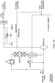
- This disclosure describes a waste heat recovery network that can be implemented to recover heat from a hydrocracking plant sub-unit and a hydro-treating plant sub-unit of a petrochemical refining system.
- heat recovered from the waste heat recovery network can be used to generate about 45 MW of power, thereby producing power from waste heat with a first law thermal efficiency of approximately 11.8%.
- the waste heat recovery network described here can be implemented either in its entirety or in phases. Each phase can be separately implemented without hindering previously implemented phases or future phases.
- the minimum approach temperature used in the waste heat recovery network described here can be as low as 3°C. Alternatively, higher minimum approach temperatures can be used in the beginning to achieve lower waste heat recovery.
- Waste heat recovery network can be retrofitted to an existing petrochemical refining system layout, thereby decreasing a quantity of work needed to change the existing design topology of the petrochemical refining system.
- the waste heat recovery network includes a heating fluid circuit thermally coupled to multiple heat sources, for example, ten heat sources, from a hydrocracking plant and a hydro-treating plant.
- the heat recovered using the waste heat recovery network can be provided to a power generation system that comprises an Organic Rankine Cycle (ORC).
- ORC Organic Rankine Cycle
- the design configuration of the waste heat recovery network and the processes implemented using the waste heat recovery network need not change with future efforts inside individual plants to enhance energy efficiency. The design configuration and the processes also need not be changed in response to other improvements to waste heat recovery in the petrochemical refining system.
- the waste heat recovery network uses low-low grade waste heat, that is, waste heat less than about 160°C.
- FIG. 1A is a schematic diagram of an example system 100 to recover waste heat from ten heat sources.
- FIGS. 1B-1D are schematic diagrams of seven heat sources in a hydrocracking plant.
- FIGS. IE and IF are schematic diagrams of three heat sources in a diesel hydro-treating plant.
- FIG. 1G is a schematic diagram of an implementation of the example network of FIG. 1A .
- FIG. 1A is a schematic diagram of an example system 100 to recover waste heat from ten sources.
- the system 100 can include a heating fluid circuit 102 thermally coupled to multiple heat sources.
- the multiple heat sources can include seven heat exchangers (a first heat exchanger 102a, a second heat exchanger 102b, a third heat exchanger 102c, a fourth heat exchanger 102d, a fifth heat exchanger 102e, a sixth heat exchanger 102f, and a seventh heat exchanger 102g) coupled to a hydrocracking plant of a petrochemical refining system.
- the multiple heat sources can also include three heat exchangers (an eighth heat exchanger 102h, a ninth heat exchanger 102i, and a tenth heat exchanger 102j) coupled to a diesel hydro-treating plant of the petrochemical refining system.
- the ten heat sources can be connected in parallel.
- the example system 100 can include a power generation system 104 that includes an organic Rankine cycle (ORC).
- ORC organic Rankine cycle
- the ORC can include a working fluid that is thermally coupled to the heating fluid circuit 102 to heat the working fluid.
- the working fluid can be isobutane.
- the ORC can also include a gas expander 112 configured to generate electrical power from the heated working fluid.
- the ORC can additionally include an evaporator 106, a pump 108 and a condenser 110.
- the working fluid can be thermally coupled to the heating fluid circuit 102 in the evaporator 106.
- a heating fluid for example, water, oil, or other fluid
- An inlet temperature of the heating fluid that is circulated into the inlets of each of the ten heat sources is the same or substantially the same subject to any temperature variations that may result as the heating fluid flows through respective inlets.
- Each heat exchanger heats the heating fluid to a respective temperature that is greater than the inlet temperature.
- the heated heating fluids from the ten heat exchangers are combined and flowed through the evaporator 106 of the ORC. Heat from the heated heating fluid heats the working fluid of the ORC thereby increasing the working fluid temperature and evaporating the working fluid.
- the heat exchange with the working fluid results in a decrease in the temperature of the heating fluid.
- the heating fluid is then collected in a heating fluid tank 116 and can be pumped back through the ten heat exchangers to restart the waste heat recovery cycle.
- the heating fluid that exits the evaporator 106 can be flowed through an air cooler 114 to further cool the heating fluid before the heating fluid is collected in the heating fluid tank 116.
- the heating fluid circuit to flow heating fluid through the ten heat exchangers can include multiple valves that can be operated manually or automatically.
- the hydrocracking plant and the diesel hydro-treating plant can be fitted with the heating fluid flow pipes and valves.
- An operator can manually open each valve in the circuit to cause the heating fluid to flow through the circuit.
- the operator can manually close each valve in the circuit.
- a control system for example, a computer-controlled control system, can be connected to each valve in the circuit.
- the control system can automatically control the valves based, for example, on feedback from sensors (for example, temperature, pressure or other sensors), installed at different locations in the circuit.
- the control system can also be operated by an operator.
- the heating fluid can be looped through the ten heat exchangers to recover heat that would otherwise go to waste in the hydrocracking and diesel hydro-treating plants, and to use the recovered waste heat to operate the power generation system.
- an amount of energy needed to operate the power generation system can be decreased while obtaining the same or substantially similar power output from the power generation system.
- the power output from the power generation system that implements the waste heat recovery network can be higher or lower than the power output from the power generation system that does not implement the waste heat recovery network. Where the power output is less, the difference may not be statistically significant. Consequently, a power generation efficiency of the petrochemical refining system can be increased.
- FIGS. 1B-1D are schematic diagrams of seven heat sources in a hydrocracking plant.
- FIG. 1B shows the first heat exchanger 102a in the hydrocracking plant of the petrochemical refining system.
- a feed stream from the 2 nd reaction section, 2 nd stage hot high pressure separator and the heating fluid flow through the first heat exchanger 102a simultaneously.
- the first heat exchanger 102a cools down the feed stream from a higher temperature, for example, about 157°C, to a lower temperature, for example, about 60°C, and increases the temperature of the heating fluid from a lower temperature, for example, from about 50°C, to a higher temperature, for example, about 152°C.
- the temperature of the heating fluid can be different from, for example, less than, 50°C depending upon available cooling media temperatures in the condenser (for example, in cold weather countries) or more than 50°C depending, for example, on design efficiencies or inefficiencies of the ORC system that render surplus heat available in the heating fluid stream after heating and vaporizing the working fluid in the ORC.
- a heating fluid temperature of about 50°C can provide increased efficiency of waste heat to power conversion.
- the thermal duty of the first heat exchanger 102a to implement the heat exchange is about 26.25 MW.
- the heating fluid at 152°C that exits the first heat exchanger 102a is circulated to a main header to be mixed with heated heating fluids from the other nine heat exchangers.
- FIG. 1C shows the second heat exchanger 102b in the hydrocracking plant of the petrochemical refining system.
- a feed stream from the 1 st reaction section, 1 st stage cold high pressure separator and the heating fluid flow through the second heat exchanger 102b simultaneously.
- the second heat exchanger 102b cools down the feed stream from a higher temperature, for example, about 159°C, to a lower temperature, for example, about 60°C, and increases the temperature of the heating fluid from a lower temperature, for example, about 50°C, to a higher temperature, for example, about 154°C.
- the thermal duty of the second heat exchanger 102b to implement the heat exchange is about 81.51 MW
- the heating fluid at 154°C that exits the second heat exchanger 102b is circulated to the main header to be mixed with heated heating fluids from the other nine heat exchangers.
- FIG. ID shows the third heat exchanger 102c, the fourth heat exchanger 102d, the fifth heat exchanger 102e, the sixth heat exchanger 102f and the seventh heat exchanger 102g in the hydrocracking plant of the petrochemical refining system.
- a feed stream from the product stripper overhead and the heating fluid flow through the third heat exchanger 102c simultaneously.
- the third heat exchanger 102c cools down the feed stream from a higher temperature, for example, about 169°C, to a lower temperature, for example, about 60°C, and increases the temperature of the heating fluid from a lower temperature, for example, about 50°C, to a higher temperature, for example, about 164°C.
- the thermal duty of the third heat exchanger 102c to implement the heat exchange is about 36.8 MW.
- the heating fluid at 164°C that exits the third heat exchanger 102c is circulated to the main header to be mixed with heated heating fluids from the other nine heat exchangers.
- the fourth heat exchanger 102d cools down the feed stream from a higher temperature, for example, about 136°C, to a lower temperature, for example, about 60°C, and increases the temperature of the heating fluid from a lower temperature, for example, about 50°C, to a higher temperature, for example, about 131°C.
- the thermal duty of the fourth heat exchanger 102d to implement the heat exchange is about 89 MW.
- the heating fluid at 131°C that exits the fourth heat exchanger 102d is circulated to the main header to be mixed with heated heating fluids from the other nine heat exchangers.
- a kerosene product stream and the heating fluid flow through the fifth heat exchanger 102e simultaneously.
- the fifth heat exchanger 102e cools down the stream from a higher temperature, for example, about 160°C, to a lower temperature, for example, about 60°C, and increases the temperature of the heating fluid from a lower temperature, for example, about 50°C, to a higher temperature, for example, about 155°C.
- the thermal duty of the fifth heat exchanger 102e to implement the heat exchange is about 19.5 MW.
- the heating fluid at 155°C that exits the fifth heat exchanger 102e is circulated to the main header to be mixed with heated heating fluids from the other nine heat exchangers.
- the sixth heat exchanger 102f cools down the stream from a higher temperature, for example, about 160°C, to a lower temperature, for example, about 60°C, and increases the temperature of the heating fluid from a lower temperature, for example, about 50°C, to a higher temperature, for example, about 155°C.
- the thermal duty of the sixth heat exchanger 102f to implement the heat exchange is about 4.65 MW.
- the thermal duties of the heat exchangers can depend upon the heat capacity flow rates of the hot oil streams flowing through the heat exchangers.
- the thermal duties of two heat exchangers can be different even when the temperature changes of the heating fluid flowing through the two heat exchangers is the same. In such instances, the heat capacity flow rates of the two heat exchangers can be different.
- the heating fluid at 155°C that exits the sixth heat exchanger 102f is circulated to the main header to be mixed with heated heating fluids from the other nine heat exchangers.
- a diesel product stream and the heating fluid flow through the seventh heat exchanger 102g simultaneously.
- the seventh heat exchanger 102g cools down the stream from a higher temperature, for example, about 160°C, to a lower temperature, for example, about 60°C, and increases the temperature of the heating fluid from a lower temperature, for example, about 50°C, to a higher temperature, for example, about 155°C.
- the thermal duty of the seventh heat exchanger 102g to implement the heat exchange is about 5.74 MW.
- the heating fluid at 155°C that exits the seventh heat exchanger 102g is circulated to the main header to be mixed with heated heating fluids from the other nine heat exchangers.
- FIGS. IE and IF are schematic diagrams of three heat sources in a diesel hydro-treating plant.
- FIG. IE shows the eighth heat exchanger 102h in the diesel hydro-treating plant of the petrochemical refining system.
- a stream from the light effluent to cold separator and the heating fluid flow through the eighth heat exchanger 102h simultaneously.
- the eighth heat exchanger 102h cools down the stream from a higher temperature, for example, about 127°C, to a lower temperature, for example, about 60°C, and increases the temperature of the heating fluid from a lower temperature, for example, from about 50°C, to a higher temperature, for example, about 122°C.
- the thermal duty of the eighth heat exchanger 102h to implement the heat exchange is about 23.4 MW.
- the heating fluid at 122°C that exits the eighth heat exchanger 102h is circulated to the main header to be mixed with heated heating fluids from the other nine heat exchangers.
- FIG. IF shows the ninth heat exchanger 102i in the diesel hydro-treating plant of the petrochemical refining system.
- a stream from the diesel stripper overhead and the heating fluid flow through the ninth heat exchanger 102i simultaneously.
- the ninth heat exchanger 102i cools down the stream from a higher temperature, for example, about 160°C, to a lower temperature, for example, about 60°C, and increases the temperature of the heating fluid from a lower temperature, for example, from about 50°C, to a higher temperature, for example, about 155°C.
- the thermal duty of the ninth heat exchanger 102i to implement the heat exchange is about 33.6 MW.
- the heating fluid at 155°C that exits the ninth heat exchanger 102i is circulated to the main header to be mixed with heated heating fluids from the other nine heat exchangers.
- a diesel stripper product stream and the heating fluid flow through the tenth heat exchanger 102j simultaneously.
- the tenth heat exchanger 102j cools down the stream from a higher temperature, for example, about 162°C, to a lower temperature, for example, about 60°C, and increases the temperature of the heating fluid from a lower temperature, for example, from about 50°C, to a higher temperature, for example, about 157°C.
- the thermal duty of the tenth heat exchanger 102j to implement the heat exchange is about 60.7 MW.
- the heating fluid at 155°C that exits the tenth heat exchanger 102h is circulated to the main header to be mixed with heated heating fluids from the other nine heat exchangers.
- the heat capacity flowrate values for the high pressure hot water system is split between the hydrocracking and the diesel hydro-treating plants.
- the flowrate values for the two plants are 2.56 MW/°C and 1.14 MW/°C, respectively.
- the total hot oil heat capacity flow rate is 3.7 MW/°C.
- This steam heat capacity flow rate is divided into two streams. The first stream is directed to the hydrocracking plant with heat capacity flow rate equal to 2.56 MW/°C and the second stream is directed to the diesel hydrotreating plant with a heat capacity flow rate equal to 1.14 MW/°C.
- FIG. 1G is a schematic diagram of an implementation of the example system 100 of FIG. 1A .
- the heating fluids received from the ten heat exchangers are mixed in the main header resulting in a heating fluid at a temperature of about 153°C.
- the heating fluid is circulated through the evaporator 106 of the ORC.
- the evaporator 106 increases the temperature of the working fluid (for example, isobutane or other working fluid) from about 31°C at 20 bar to about 99°C at 20 bar at a thermal duty of about 362 MW.
- the gas expander 112 expands the high temperature, high pressure working fluid to generate power, for example, about 45 MW, at a turbine efficiency, for example, 85%.
- the expansion decreases the temperature and pressure of the working fluid, for example, to about 52°C and about 4.3 bar, respectively.
- the working fluid flows through the condenser 110 which further decreases the temperature and pressure of the working fluid at a thermal duty of about 321 MW.
- cooling fluid flows through the condenser 110 at a lower temperature, for example, 20°C, exchanges heat with the working fluid, and exits the condenser 110 at a higher temperature, for example, about 30°C.
- the cooled working fluid (for example, isobutane liquid) is pumped by the pump 108 at an efficiency, for example, of about 75%, and an input power, for example, of about 3.5 MW.
- the pump 108 increases the temperature of the working fluid to about 31°C and pumps the working fluid at a mass flow rate of about 890 kg/s to the evaporator 106, which repeats the Rankine cycle to generate power.
- FIG. 1H is a graph that shows a tube-side fluid temperature (for example, a cooling, or condenser, fluid flow) and a shell-side fluid temperature (for example, an ORC working fluid flow) in the condenser 110 during an operation of the system 100.
- This graph shows a temperature difference between the fluids on the y-axis relative to a heat flow between the fluids on the x-axis.
- the cooling fluid medium may be at or about 20°C or even higher.
- a gas expander outlet pressure (for example, pressure of the ORC working fluid exiting the gas expander) may be high enough to allow the condensation of the ORC working fluid at the available cooling fluid temperature.
- the condenser water (entering the tubes of the condenser 110) enters at about 20°C and leaves at about 30°C.
- the ORC working fluid (entering the shell-side of the condensers) enters as a vapor at about 52°C, and then condenses at 30°C and leaves the condensers as a liquid at 30°C.
- FIG. 1I is a graph that shows a tube-side fluid temperature (for example, a heating fluid flow) and a shell-side fluid temperature (for example, an ORC working fluid flow) in the evaporator 106 during an operation of the system 100.
- This graph shows a temperature difference between the fluids on the ⁇ -axis relative to a heat flow between the fluids on the x-axis. For example, as shown in this figure, as the temperature difference between the fluids decreases, a heat flow between the fluids can increase.
- This graph shows a temperature difference between the fluids on the y-axis relative to a heat flow between the fluids on the x-axis. For example, as shown in FIG.
- the tube-side fluid for example, the hot oil or water in the heating fluid circuit 102
- the shell-side fluid for example, the ORC working fluid
- the tube-side fluid enters the evaporator 106 at about 152°C and leaves the evaporator 106 at about 55°C.
- the shell-side fluid enters the evaporator 106 at about 30°C (for example, as a liquid) and leaves the evaporator 106 at about 99°C (for example, as a vapor with some superheating).
- the techniques to recover heat energy generated by a petrochemical refining system described earlier can be implemented in at least one or both of two example scenarios.
- the techniques can be implemented in a petrochemical refining system that is to be constructed.
- a geographic layout to arrange multiple sub-units of a petrochemical refining system can be identified.
- the geographic layout can include multiple sub-unit locations at which respective sub-units are to be positioned. Identifying the geographic layout can include actively determining or calculating the location of each sub-unit in the petrochemical refining system based on particular technical data, for example, a flow of petrochemicals through the sub-units starting from crude petroleum and resulting in refined petroleum.
- Identifying the geographic layout can alternatively or in addition include selecting a layout from among multiple previously-generated geographic layouts.
- a first subset of sub-units of the petrochemical refining system can be identified.
- the first subset can include at least two (or more than two) heat-generating sub-units from which heat energy is recoverable to generate electrical power.
- a second subset of the multiple sub-unit locations can be identified.
- the second subset includes at least two sub-unit locations at which the respective sub-units in the first subset are to be positioned.
- a power generation system to recover heat energy from the sub-units in the first subset is identified.
- the power generation system can be substantially similar to the power generation system described earlier.
- a power generation system location can be identified to position the power generation system.
- a heat energy recovery efficiency is greater than a heat energy recovery efficiency at other locations in the geographic layout.
- the petrochemical refining system planners and constructors can perform modeling or computer-based simulation experiments (or both) to identify an optimal location for the power generation system to maximize heat energy recovery efficiency, for example, by minimizing heat loss when transmitting recovered heat energy from the at least two heat-generating sub-units to the power generation system.
- the petrochemical refining system can be constructed according to the geographic layout by positioning the multiple sub-units at the multiple sub-unit locations, positioning the power generation system at the power generation system location, interconnecting the multiple sub-units with each other such that the interconnected multiple sub-units are configured to refine petrochemicals, and interconnecting the power generation system with the sub-units in the first subset such that the power generation system is configured to recover heat energy from the sub-units in the first subset and to provide the recovered heat energy to the power generation system.
- the power generation system is configured to generate power using the recovered heat energy.
- the techniques can be implemented in an operational petrochemical refining system.
- the power generation system described earlier can be retrofitted to an already constructed and operational petrochemical refining system.
- Implementations of the subject matter described here can increase an energy output of petrochemical refining systems by about 41.6 MW for local utilization or export to an electricity grid. In this manner, the carbon consumption and GHG emissions of the plant can be decreased.
Description
- This specification relates to power generation in industrial facilities.
- Petroleum refining processes are chemical engineering processes and other facilities used in petroleum refineries to transform crude oil into products, for example, liquefied petroleum gas (LPG), gasoline, kerosene, jet fuel, diesel oils, fuel oils, and other products. Petroleum refineries are large industrial complexes that involve many different processing units and auxiliary facilities, for example, utility units, storage tanks, and other auxiliary facilities. Each refinery can have its own unique arrangement and combination of refining processes determined, for example, by the refinery location, desired products, economic considerations, or other factors. The petroleum refining processes that are implemented to transform the crude oil into the products such as those listed earlier can generate heat, which may not be re-used, and byproducts, for example, greenhouse gases (GHG), which may pollute the atmosphere. It is believed that the world's environment has been negatively affected by global warming caused, in part, due to the release of GHG into the atmosphere.
-
US 2012/0031096 describes methods for generating electrical power from low grade heat sources from refining and petrochemical processes, including overhead vapors from vapor-liquid contacting apparatuses such as distillation columns, absorbers, strippers, quenching towers, scrubbers, etc. Rather than rejecting the low temperature heat contained in these vapors to cooling air and/or cooling water, the vapors may instead be used to evaporate an organic working fluid. The vapors of the working fluid may then be sent to a turbine to drive a generator or other load. -
US 2008/0289588 describes an apparatus and process for recovering heat from multiple hot process streams without multiplying instrumentation. Each hot process stream is indirectly heat exchanged with a water circuit which leaves and feeds a steam drum. Heat is added to the steam drum through the addition of water heated outside of the steam drum. The heated liquid and vapor water is heated in heat exchangers decoupled from the steam drum. The water circuits are arranged in parallel with each other and feed a single steam drum to provide a steam product of a desired pressure for which only one set of instrumentation is needed. - This specification describes technologies relating to power generation from waste energy in industrial facilities. The present disclosure includes one or more of the following units of measure with their corresponding abbreviations, as shown in Table 1:
TABLE 1 Unit of Measure Abbreviation Degrees Celsius °C Megawatts MW One million MM British thermal unit Btu Hour h Pounds per square inch (pressure) psi Kilogram (mass) Kg Second S - The details of one or more implementations of the subject matter described in this specification are set forth in the accompanying drawings and the description later. Other features, aspects, and advantages of the subject matter will become apparent from the description, the drawings, and the claims.
-
-
FIG. 1A is a schematic diagram of an example system to recover waste heat from ten heat sources. -
FIGS. 1B ,1C , IDA and 1DB are schematic diagrams of seven heat sources in a hydrocracking plant. - FIGS. IE and IF are schematic diagrams of three heat sources in a diesel hydro-treating plant.
-
FIG. 1G is a schematic diagram of an implementation of the example network ofFIG. 1A . -
FIG. 1H is a graph that shows a tube-side fluid temperature and a shell-side fluid temperature in the condenser during an operation of the system described with reference toFIG. 1A . -
FIG. 1I is a graph that shows a tube-side fluid temperature and a shell-side fluid temperature in the evaporator during an operation of the system described with reference toFIG. 1A . - Industrial waste heat is a source for potential carbon-free power generation in many industrial facilities, for example, crude oil refineries, petrochemical and chemical complexes, and other industrial facilities. For example, a medium-size integrated crude oil refinery with aromatics up to 4200x106 KJ/h (4,000 MMBtu/h) can be wasted to a network of air coolers extended along the crude oil and aromatics site. Some of the wasted heat can be used to power an Organic Rankine Cycle (ORC) machine, which uses an organic fluid such as refrigerants or hydrocarbons (or both) instead of water to generate power. ORC machines in combination with low temperature heat sources (for example, about or less than 232°C) are being implemented as power generation systems. Optimizing ORC machines, for example, by optimizing the power generation cycle (that is, the Rankine cycle) or the organic fluid implemented by the ORC machine (or both), can improve power generation from recovered waste heat.
- An industrial facility such as a petroleum refinery includes several sources of waste heat. One or more ORC machines can receive the waste heat from one or more or all of such sources. In some implementations, two or more sources of low grade heat can be consolidated by transferring heat from each of the sources to a common intermediate heat transfer medium (for example, water or other fluid). The intermediate heat transfer medium can then be used to evaporate the working fluid of the ORC machine to generate power, for example, to operate a turbine or other power generator. Such consolidation of sources of low grade heat can allow the ORC machine to be sized to realize greater efficiencies and economies of scale. Further, such a consolidated operation can improve flexibility in petroleum refinery design and plot space planning, since each heat source need not be in close proximity to the power generator. The proposed consolidation of heat sources, particularly, in mega sites such as a site-wide oil refinery that includes an aromatics complex and is the size of an eco-industrial park can represent an over-simplification of the problem of improving the process of recovering waste heat to generate power.
- This disclosure describes optimizing power generation from waste heat, for example, low grade heat at a temperature at or less than 160°C, in large industrial facilities (for example, petroleum refineries or other large industrial refineries with several, sometimes more than 50, hot source streams) by utilizing a subset of all available hot source streams selected based, in part, on considerations for example, capital cost, ease of operation, economics of scale power generation, a number of ORC machines to be operated, operating conditions of each ORC machine, combinations of them, or other considerations. Recognizing that several subsets of hot sources can be identified from among the available hot sources in a large petroleum refinery, this disclosure describes selecting subsets of hot sources that are optimized to provide waste heat to one or more ORC machines for power generation. Further, recognizing that the utilization of waste heat from all available hot sources in a mega-site such as a petroleum refinery and aromatics complex is not necessarily or not always the best option, this disclosure identifies hot source units in petroleum refineries from which waste heat can be consolidated to power the one or more ORC machines.
- This disclosure also describes modifying medium grade crude oil refining semi-conversion facilities and integrated medium grade crude oil refining semi-conversion and aromatics facilities plants' designs to improve their energy efficiencies relative to their current designs. To do so, new facilities can be designed or existing facilities can be re-designed (for example, retro-fitted with equipment) to recover waste heat, for example, low grade waste heat, from heat sources to power ORC machines. In particular, the existing design of a plant need not be significantly altered to accommodate the power generation techniques described here. The generated power can be used, in part, to power the facilities or transported to the electricity grid to be delivered elsewhere (or both).
- By recovering all or part of the waste heat generated by one or more processes or facilities (or both) of industrial facilities and converting the recovered waste heat into power, carbon-free power (for example, in the form of electricity) can be generated for use by the community. The minimum approach temperature used in the waste heat recovery processes can be as low as 3°C and the generated power can be as high as 80 MW. In some implementations, higher minimum approach temperatures can be used in an initial phase at the expense of less waste heat/energy recovery, while relatively better power generation (for example, in terms of economy of scale design and efficiency) is realized in a subsequent phase upon using the minimum approach temperature for the specific hot sources uses. In such situations, more power generation can be realized in the subsequent phase without needing to change the design topology of the initial phase or the subset of the low grade waste hot sources used in the initial phase (or both).
- Not only pollution associated but also cost associated with power generation can be decreased. In addition, recovering waste heat from a customized group of hot sources to power one or more ORC machines is more optimal than recovering waste heat from all available hot sources. Selecting the hot sources in the customized group instead of or in addition to optimizing the ORC machine can improve or optimize (or both) the process of generating power from recovered waste heat. If a few number of hot sources are used for power generation, then the hot sources can be consolidated into few (for example, one or two) buffer streams using fluids, for example, hot oil or high pressure hot water system, or a mixture of the two.
- In sum, this disclosure describes several petroleum refinery-wide separation/distillation networks, configurations, and processing schemes for efficient power generation using a basic ORC machine operating under specified conditions. The power generation is facilitated by obtaining all or part of waste heat, for example, low grade waste heat, carried by multiple, scattered low grade energy quality process streams. In some implementations, the ORC machine uses separate organic material to pre-heat the exchanger and evaporator and uses other organic fluid, for example, isobutane, at specific operating conditions.
- Industrial waste heat is a source for potential carbon-free power generation in many industrial facilities, for example, crude oil refineries, petrochemical and chemical complexes, and other industrial facilities. For example, a medium-size integrated crude oil refinery with aromatics up to 4200x106 KJ/h (4,000 MMBtu/h) can be wasted to a network of air coolers extended along the crude oil and aromatics site. Some of the wasted heat can be used to power an Organic Rankine Cycle (ORC) machine, which uses an organic fluid such as refrigerants or hydrocarbons (or both) instead of water to generate power. ORC machines in combination with low temperature heat sources (for example, about or less than 232°C) are being implemented as power generation systems. Optimizing ORC machines, for example, by optimizing the power generation cycle (that is, the Rankine cycle) or the organic fluid implemented by the ORC machine (or both), can improve power generation from recovered waste heat.
- An industrial facility such as a petroleum refinery includes several sources of waste heat. One or more ORC machines can receive the waste heat from one or more or all of such sources. In some implementations, two or more sources of low grade heat can be consolidated by transferring heat from each of the sources to a common intermediate heat transfer medium (for example, water or other fluid). The intermediate heat transfer medium can then be used to evaporate the working fluid of the ORC machine to generate power, for example, to operate a turbine or other power generator. Such consolidation of sources of low grade heat can allow the ORC machine to be sized to realize greater efficiencies and economies of scale. Further, such a consolidated operation can improve flexibility in petroleum refinery design and plot space planning, since each heat source need not be in close proximity to the power generator. The proposed consolidation of heat sources, particularly, in mega sites such as a site-wide oil refinery that includes an aromatics complex and is the size of an eco-industrial park can represent an over-simplification of the problem of improving the process of recovering waste heat to generate power.
- This disclosure describes optimizing power generation from waste heat, for example, low grade heat at a temperature at or less than 160°C, in large industrial facilities (for example, petroleum refineries or other large industrial refineries with several, sometimes more than 50, hot source streams) by utilizing a subset of all available hot source streams selected based, in part, on considerations for example, capital cost, ease of operation, economics of scale power generation, a number of ORC machines to be operated, operating conditions of each ORC machine, combinations of them, or other considerations. Recognizing that several subsets of hot sources can be identified from among the available hot sources in a large petroleum refinery, this disclosure describes selecting subsets of hot sources that are optimized to provide waste heat to one or more ORC machines for power generation. Further, recognizing that the utilization of waste heat from all available hot sources in a mega-site such as a petroleum refinery and aromatics complex is not necessarily or not always the best option, this disclosure identifies hot source units in petroleum refineries from which waste heat can be consolidated to power the one or more ORC machines.
- This disclosure also describes modifying medium grade crude oil refining semi-conversion facilities and integrated medium grade crude oil refining semi-conversion and aromatics facilities plants' designs to improve their energy efficiencies relative to their current designs. To do so, new facilities can be designed or existing facilities can be re-designed (for example, retro-fitted with equipment) to recover waste heat, for example, low grade waste heat, from heat sources to power ORC machines. In particular, the existing design of a plant need not be significantly altered to accommodate the power generation techniques described here. The generated power can be used, in part, to power the facilities or transported to the electricity grid to be delivered elsewhere (or both).
- By recovering all or part of the waste heat generated by one or more processes or facilities of industrial facilities (or both) and converting the recovered waste heat into power, carbon-free power (for example, in the form of electricity) can be generated for use by the community. The minimum approach temperature used in the waste heat recovery processes can be as low as 3°C and the generated power can be as high as 80 MW. In some implementations, higher minimum approach temperatures can be used in an initial phase at the expense of less waste heat/energy recovery, while relatively better power generation (for example, in terms of economy of scale design and efficiency) is realized in a subsequent phase upon using the minimum approach temperature for the specific hot sources uses. In such situations, more power generation can be realized in the subsequent phase without needing to change the design topology of the initial phase or the subset of the low grade waste hot sources used in the initial phase (or both).
- Not only pollution associated but also cost associated with power generation can be decreased. In addition, recovering waste heat from a customized group of hot sources to power one or more ORC machines is more cost effective from a capital cost point-of-view than recovering waste heat from all available hot sources. Selecting the hot sources in the customized group instead of or in addition to optimizing the ORC machine can improve or optimize the process of generating power from recovered waste heat (or both). If a few number of hot sources are used for power generation, then the hot sources can be consolidated into few (for example, one or two) buffer streams using fluids, for example, hot oil or high pressure hot water system (or both).
- In sum, this disclosure describes several petroleum refinery-wide separation/distillation networks, configurations, and processing schemes for efficient power generation using a basic ORC machine operating under specified conditions. The power generation is facilitated by obtaining all or part of waste heat, for example, low grade waste heat, carried by multiple, scattered low grade energy quality process streams. In some implementations, the ORC machine uses separate organic material to pre-heat the exchanger and evaporator and uses other organic fluid, for example, isobutane, at specific operating conditions.
- Hydrocracking is a two-stage process combining catalytic cracking and hydrogenation. In this process heavy feedstocks are cracked in the presence of hydrogen to produce more desirable products. The process employs high pressure, high temperature, a catalyst, and hydrogen. Hydrocracking is used for feedstocks that are difficult to process by either catalytic cracking or reforming, since these feedstocks are characterized usually by high polycyclic aromatic content or high concentrations of the two principal catalyst poisons, sulfur and nitrogen compounds (or both).
- The hydrocracking process depends on the nature of the feedstock and the relative rates of the two competing reactions, hydrogenation and cracking. Heavy aromatic feedstock is converted into lighter products under a wide range of high pressures and high temperatures in the presence of hydrogen and special catalysts. When the feedstock has a high paraffinic content, hydrogen prevents the formation of polycyclic aromatic compounds. Hydrogen also reduces tar formation and prevents buildup of coke on the catalyst. Hydrogenation additionally converts sulfur and nitrogen compounds present in the feedstock to hydrogen sulfide and ammonia. Hydrocracking produces isobutane for alkylation feedstock, and also performs isomerization for pour-point control and smoke-point control, both of which are important in high-quality jet fuel.
- Hydrotreating is a refinery process for reducing sulfur, nitrogen and aromatics while enhancing cetane number, density and smoke point. Hydrotreating assists the refining industry's efforts to meet the global trend for stringent clean fuels specifications, the growing demand for transportation fuels and the shift toward diesel. In this process, fresh feed is heated and mixed with hydrogen. Reactor effluent exchanges heat with the combined feed and heats recycle gas and stripper charge. Sulphide (for example, ammonium bisulphide and hydrogen sulphide) is then removed from the feed.
- A typical aromatics complex includes a combination of process units for the production of basic petrochemical intermediates of benzene, toluene and xylenes (BTX) using the catalytic reforming of naphtha using continuous catalyst regeneration (CCR) technology.
- A Naphtha Hydrotreater (NHT) produces 101 Research Octane Number (RON) reformate, with a maximum 4.0 psi Reid Vapor Pressure (RVP), as a blending stock in the gasoline pool. It usually has the flexibility to process blends of Naphtha from the Crude Unit, Gas Condensate Splitter, Hydrocracker, Light Straight-Run Naphtha (LSRN) and Visbreaker Plants. The NHT processes naphtha to produce desulfurized feed for the continuous catalyst regeneration (CCR) platformer and gasoline blending.
- Normally, a two-stage distillation plant processes various crude oils that are fractionated into different products, which are further processed in downstream facilities to produce liquefied petroleum gas (LPG), Naphtha, Motor Gasoline, Kerosene, Jet Fuel, Diesel, Fuel Oil and Asphalt. The Crude Distillation plant can typically process large volumes, for example, hundreds of thousands of barrels, of crude oil per day. During the summer months the optimum processing capacity may decrease. The plant can process mixture of crudes. The plant can also have asphalt producing facilities. The products from crude distillation plant are LPG, stabilized whole naphtha, kerosene, diesel, heavy diesel, and vacuum residuum. The Atmospheric Column receives the crude charge and separates it into overhead product, kerosene, diesel, and reduced crude. The Naphtha stabilizer may receive the atmospheric overhead stream and separates it into LPG and stabilized naphtha. The reduced crude is charged to the Vacuum tower where it is further separated into heavy diesel, vacuum gas oils and vacuum residuum.
- The SWSUP receives sour water streams from acid gas removal, sulfur recovery, and flare units, and the sour gas stripped and released from the soot water flash vessel. The SWSUP strips the sour components, primarily carbon dioxide (CO2), hydrogen sulfide (H2S) and ammonia (NH3), from the sour water stream.
- One of more of the refinery plants described earlier can supply heat, for example, in the form of low grade waste heat, to the ORC machine with reasonable economics of scale, for example, tens of megawatts of power. Studies have shown that particular refinery plants, for example, a hydrocracking plant, serve as good waste heat sources to generate power. However, in a study using only the hot source from the naphtha hydrotreating (NHT) plant, for example, at about 111°C, 1.7 MW of power was produced from about 27.6 MW of available waste heat at a low efficiency of about 6.2%. The low efficiency suggests that a hot source from the NHT plant alone is not recommended for waste heat generation due to high capital and economy of scale. In another study using one low grade hot source at about 97°C from a crude distillation plant, 3.5 MW of power was produced from about 64.4 MW of available waste heat at a low efficiency of 5.3%. In a further study using one low grade hot source at about 120°C from a sour water stripping plant, 2.2 MW of power was produced from about 32.7 MW of available waste heat at a low efficiency of 6.7%. These studies reveal that if waste heat recovery from a particular refinery plant to generate power is determined to be beneficial, it does not necessarily follow that waste heat recovery from any refinery plant will also be beneficial.
- In another study, all waste heat available from all hot sources (totaling 11 hot source streams) in an aromatics complex were collected to generate about 13 MW of power from about 241 MW of available waste heat. This study reveals that using all available hot sources, while theoretically efficient, does not, in practice, necessarily translate to efficient power generation from available waste heat. Moreover, assembling power plants that can use all available hot sources can be very difficult considering the quantity of heat exchangers, pumps, and organic-based turbines (among other components and inter-connectors) involved. Not only will it be difficult to retrofit existing refineries to accommodate such power plants, but it will also be difficult to build such power plants from a grass roots stage. In the following sections, this disclosure describes combinations of hot sources selected from different refinery plants which can result in high efficiencies in generating power from available waste heat.
- Even after identifying specific hot sources to be used for power generation in a mega-size site, there can be several combinations of hot sources that can be integrated for optimum generation of power using a specific ORC machine operating under specific conditions. Each of the following sections describes a specific combination of hot sources and a configuration for buffer systems which can be implemented with the specific combination to optimally generate power from waste heat with as minimum capital utilization as necessary. Also, the following sections describe two-buffer systems for low grade waste heat recovery where one-buffer systems for waste heat recovery as inapplicable. Each section describes the interconnections and related processing schemes between the different plants that make up the specific combination of hot sources, the configurations including components such as heat exchangers added in specific plants, at specific places and to specific streams in the process to optimize waste heat recovery and power generation. As described later, the different configurations can be implemented without changing the current layout or processes implemented by the different plants. The new configurations described in the sections later can generate between about 34 MW and about 80 MW of power from waste heat, enabling a proportional decrease of GHG emissions in petroleum refineries. The configurations described in the sections later demonstrate more than one way to achieve desired energy recovery using buffer systems. The configurations are related processing schemes do not impact and can be integrated with future potential in-plant energy saving initiatives, for example, low pressure steam generation. The configurations and processing schemes can render more than 10% first law efficiency for power generation from the low grade waste heat into the ORC machine.
- In the configurations described in this disclosure, heat exchangers are used to transfer heat from one medium (for example, a stream flowing through a plant in a crude oil refining facility, a buffer fluid or other medium) to another medium (for example, a buffer fluid or different stream flowing through a plant in the crude oil facility). Heat exchangers are devices which transfer (exchange) heat typically from a hotter fluid stream to a relatively less hotter fluid stream. Heat exchangers can be used in heating and cooling applications, for example, in refrigerators, air conditions or other cooling applications. Heat exchangers can be distinguished from one another based on the direction in which liquids flow. For example, heat exchangers can be parallel-flow, cross-flow or counter-current. In parallel-flow heat exchangers, both fluid involved move in the same direction, entering and exiting the heat exchanger side-by-side. In cross-flow heat exchangers, the fluid path runs perpendicular to one another. In counter-current heat exchangers, the fluid paths flow in opposite directions, with one fluid exiting whether the other fluid enters. Counter-current heat exchangers are sometimes more effective than the other types of heat exchangers.
- In addition to classifying heat exchangers based on fluid direction, heat exchangers can also be classified based on their construction. Some heat exchangers are constructed of multiple tubes. Some heat exchangers include plates with room for fluid to flow in between. Some heat exchangers enable heat exchange from liquid to liquid, while some heat exchangers enable heat exchange using other media.
- Heat exchangers in crude oil refining and petrochemical facilities are often shell and tube type heat exchangers which include multiple tubes through which liquid flows. The tubes are divided into two sets - the first set contains the liquid to be heated or cooled; the second set contains the liquid responsible for triggering the heat exchange, in other words, the fluid that either removes heat from the first set of tubes by absorbing and transmitting the heat away or warms the first set by transmitting its own heat to the liquid inside. When designing this type of exchanger, care must be taken in determining the correct tube wall thickness as well as tube diameter, to allow optimum heat exchange. In terms of flow, shell and tube heat exchangers can assume any of three flow path patterns.
- Heat exchangers in crude oil refining and petrochemical facilities can also be plate and frame type heat exchangers. Plate heat exchangers include thin plates joined together with a small amount of space in between, often maintained by a rubber gasket. The surface area is large, and the corners of each rectangular plate feature an opening through which fluid can flow between plates, extracting heat from the plates as it flows. The fluid channels themselves alternate hot and cold liquids, meaning that the heat exchangers can effectively cool as well as heat fluid. Because plate heat exchangers have large surface area, they can sometimes be more effective than shell and tube heat exchangers.
- Other types of heat exchangers can include regenerative heat exchangers and adiabatic wheel heat exchangers. In a regenerative heat exchanger, the same fluid is passed along both sides of the exchanger, which can be either a plate heat exchanger or a shell and tube heat exchanger. Because the fluid can get very hot, the exiting fluid is used to warm the incoming fluid, maintaining a near constant temperature. Energy is saved in a regenerative heat exchanger because the process is cyclical, with almost all relative heat being transferred from the exiting fluid to the incoming fluid. To maintain a constant temperature, a small quantity of extra energy is needed to raise and lower the overall fluid temperature. In the adiabatic wheel heat exchanger, an intermediate liquid is used to store heat, which is then transferred to the opposite side of the heat exchanger. An adiabatic wheel consists of a large wheel with treads that rotate through the liquids - both hot and cold - to extract or transfer heat. The heat exchangers described in this disclosure can include any one of the heat exchangers described earlier, other heat exchangers, or combinations of them.
- Each heat exchanger in each configuration can be associated with a respective thermal duty (or heat duty). The thermal duty of a heat exchanger can be defined as an amount of heat that can be transferred by the heat exchanger from the hot stream to the cold stream. The amount of heat can be calculated from the conditions and thermal properties of both the hot and cold streams. From the hot stream point of view, the thermal duty of the heat exchanger is the product of the hot stream flow rate, the hot stream specific heat, and a difference in temperature between the hot stream inlet temperature to the heat exchanger and the hot stream outlet temperature from the heat exchanger. From the cold stream point of view, the thermal duty of the heat exchanger is the product of the cold stream flow rate, the cold stream specific heat and a difference in temperature between the cold stream outlet from the heat exchanger and the cold stream inlet temperature from the heat exchanger. In several applications, the two quantities can be considered equal assuming no heat loss to the environment for these units, particularly, where the units are well insulated. The thermal duty of a heat exchanger can be measured in watts (W), megawatts (MW), millions of British Thermal Units per hour (Btu/hr), or millions of kilocalories per hour (Kcal/h). In the configurations described here, the thermal duties of the heat exchangers are provided as being "about X MW," where "X" represents a numerical thermal duty value. The numerical thermal duty value is not absolute. That is, the actual thermal duty of a heat exchanger can be approximately equal to X, greater than X or less than X.
- In each of the configurations described later, process streams (also called "streams") are flowed within each plant in a crude oil refining facility and between plants in the crude oil refining facility. The process streams can be flowed using one or more flow control systems implemented throughout the crude oil refining facility. A flow control system can include one or more flow pumps to pump the process streams, one or more flow pipes through which the process streams are flowed and one or more valves to regulate the flow of streams through the pipes.
- In some implementations, a flow control system can be operated manually. For example, an operator can set a flow rate for each pump and set valve open or close positions to regulate the flow of the process streams through the pipes in the flow control system. Once the operator has set the flow rates and the valve open or close positions for all flow control systems distributed across the crude oil refining facility, the flow control system can flow the streams within a plant or between plants under constant flow conditions, for example, constant volumetric rate or other flow conditions. To change the flow conditions, the operator can manually operate the flow control system, for example, by changing the pump flow rate or the valve open or close position.
- In some implementations, a flow control system can be operated automatically. For example, the flow control system can be connected to a computer system to operate the flow control system. The computer system can include a computer-readable medium storing instructions (such as flow control instructions and other instructions) executable by one or more processors to perform operations (such as flow control operations). An operator can set the flow rates and the valve open or close positions for all flow control systems distributed across the crude oil refining facility using the computer system. In such implementations, the operator can manually change the flow conditions by providing inputs through the computer system. Also, in such implementations, the computer system can automatically (that is, without manual intervention) control one or more of the flow control systems, for example, using feedback systems implemented in one or more plants and connected to the computer system. For example, a sensor (such as a pressure sensor, temperature sensor or other sensor) can be connected to a pipe through which a process stream flows. The sensor can monitor and provide a flow condition (such as a pressure, temperature, or other flow condition) of the process stream to the computer system. In response to the flow condition exceeding a threshold (such as a threshold pressure value, a threshold temperature value, or other threshold value), the computer system can automatically perform operations. For example, if the pressure or temperature in the pipe exceeds the threshold pressure value or the threshold temperature value, respectively, the computer system can provide a signal to the pump to decrease a flow rate, a signal to open a valve to relieve the pressure, a signal to shut down process stream flow, or other signals.
- This disclosure describes a waste heat recovery network that can be implemented to recover heat from a hydrocracking plant sub-unit and a hydro-treating plant sub-unit of a petrochemical refining system. As described later, heat recovered from the waste heat recovery network can be used to generate about 45 MW of power, thereby producing power from waste heat with a first law thermal efficiency of approximately 11.8%. The waste heat recovery network described here can be implemented either in its entirety or in phases. Each phase can be separately implemented without hindering previously implemented phases or future phases. The minimum approach temperature used in the waste heat recovery network described here can be as low as 3°C. Alternatively, higher minimum approach temperatures can be used in the beginning to achieve lower waste heat recovery. By decreasing the minimum approach temperature over time, reasonable power generation economies of scale can be used and higher power generation efficiency can be realized. Efficiency can also be increased by using a sub-set of the waste heat streams that are used in the network. The waste heat recovery network can be retrofitted to an existing petrochemical refining system layout, thereby decreasing a quantity of work needed to change the existing design topology of the petrochemical refining system.
- The waste heat recovery network includes a heating fluid circuit thermally coupled to multiple heat sources, for example, ten heat sources, from a hydrocracking plant and a hydro-treating plant. The heat recovered using the waste heat recovery network can be provided to a power generation system that comprises an Organic Rankine Cycle (ORC). The design configuration of the waste heat recovery network and the processes implemented using the waste heat recovery network need not change with future efforts inside individual plants to enhance energy efficiency. The design configuration and the processes also need not be changed in response to other improvements to waste heat recovery in the petrochemical refining system. The waste heat recovery network uses low-low grade waste heat, that is, waste heat less than about 160°C.
-
FIG. 1A is a schematic diagram of anexample system 100 to recover waste heat from ten heat sources.FIGS. 1B-1D are schematic diagrams of seven heat sources in a hydrocracking plant. FIGS. IE and IF are schematic diagrams of three heat sources in a diesel hydro-treating plant.FIG. 1G is a schematic diagram of an implementation of the example network ofFIG. 1A . -
FIG. 1A is a schematic diagram of anexample system 100 to recover waste heat from ten sources. In some implementations, thesystem 100 can include aheating fluid circuit 102 thermally coupled to multiple heat sources. For example, the multiple heat sources can include seven heat exchangers (afirst heat exchanger 102a, asecond heat exchanger 102b, athird heat exchanger 102c, afourth heat exchanger 102d, afifth heat exchanger 102e, asixth heat exchanger 102f, and aseventh heat exchanger 102g) coupled to a hydrocracking plant of a petrochemical refining system. The multiple heat sources can also include three heat exchangers (aneighth heat exchanger 102h, aninth heat exchanger 102i, and atenth heat exchanger 102j) coupled to a diesel hydro-treating plant of the petrochemical refining system. In some implementations, the ten heat sources can be connected in parallel. - The
example system 100 can include apower generation system 104 that includes an organic Rankine cycle (ORC). The ORC can include a working fluid that is thermally coupled to theheating fluid circuit 102 to heat the working fluid. In some implementations, the working fluid can be isobutane. The ORC can also include agas expander 112 configured to generate electrical power from the heated working fluid. As shown inFIG. 1A , the ORC can additionally include anevaporator 106, apump 108 and acondenser 110. In some implementations, the working fluid can be thermally coupled to theheating fluid circuit 102 in theevaporator 106. - In operation, a heating fluid (for example, water, oil, or other fluid) is circulated through the ten heat exchangers. An inlet temperature of the heating fluid that is circulated into the inlets of each of the ten heat sources is the same or substantially the same subject to any temperature variations that may result as the heating fluid flows through respective inlets. Each heat exchanger heats the heating fluid to a respective temperature that is greater than the inlet temperature. The heated heating fluids from the ten heat exchangers are combined and flowed through the
evaporator 106 of the ORC. Heat from the heated heating fluid heats the working fluid of the ORC thereby increasing the working fluid temperature and evaporating the working fluid. The heat exchange with the working fluid results in a decrease in the temperature of the heating fluid. The heating fluid is then collected in aheating fluid tank 116 and can be pumped back through the ten heat exchangers to restart the waste heat recovery cycle. In some implementations, the heating fluid that exits theevaporator 106 can be flowed through anair cooler 114 to further cool the heating fluid before the heating fluid is collected in theheating fluid tank 116. - The heating fluid circuit to flow heating fluid through the ten heat exchangers can include multiple valves that can be operated manually or automatically. For example, the hydrocracking plant and the diesel hydro-treating plant can be fitted with the heating fluid flow pipes and valves. An operator can manually open each valve in the circuit to cause the heating fluid to flow through the circuit. To cease waste heat recovery, for example, to perform repair or maintenance or for other reasons, the operator can manually close each valve in the circuit. Alternatively, a control system, for example, a computer-controlled control system, can be connected to each valve in the circuit. The control system can automatically control the valves based, for example, on feedback from sensors (for example, temperature, pressure or other sensors), installed at different locations in the circuit. The control system can also be operated by an operator.
- In the manner described earlier, the heating fluid can be looped through the ten heat exchangers to recover heat that would otherwise go to waste in the hydrocracking and diesel hydro-treating plants, and to use the recovered waste heat to operate the power generation system. By doing so, an amount of energy needed to operate the power generation system can be decreased while obtaining the same or substantially similar power output from the power generation system. For example, the power output from the power generation system that implements the waste heat recovery network can be higher or lower than the power output from the power generation system that does not implement the waste heat recovery network. Where the power output is less, the difference may not be statistically significant. Consequently, a power generation efficiency of the petrochemical refining system can be increased.
-
FIGS. 1B-1D are schematic diagrams of seven heat sources in a hydrocracking plant.FIG. 1B shows thefirst heat exchanger 102a in the hydrocracking plant of the petrochemical refining system. A feed stream from the 2nd reaction section, 2nd stage hot high pressure separator and the heating fluid flow through thefirst heat exchanger 102a simultaneously. Thefirst heat exchanger 102a cools down the feed stream from a higher temperature, for example, about 157°C, to a lower temperature, for example, about 60°C, and increases the temperature of the heating fluid from a lower temperature, for example, from about 50°C, to a higher temperature, for example, about 152°C. The temperature of the heating fluid can be different from, for example, less than, 50°C depending upon available cooling media temperatures in the condenser (for example, in cold weather countries) or more than 50°C depending, for example, on design efficiencies or inefficiencies of the ORC system that render surplus heat available in the heating fluid stream after heating and vaporizing the working fluid in the ORC. In some implementations, a heating fluid temperature of about 50°C can provide increased efficiency of waste heat to power conversion. The thermal duty of thefirst heat exchanger 102a to implement the heat exchange is about 26.25 MW. The heating fluid at 152°C that exits thefirst heat exchanger 102a is circulated to a main header to be mixed with heated heating fluids from the other nine heat exchangers. -
FIG. 1C shows thesecond heat exchanger 102b in the hydrocracking plant of the petrochemical refining system. A feed stream from the 1st reaction section, 1st stage cold high pressure separator and the heating fluid flow through thesecond heat exchanger 102b simultaneously. Thesecond heat exchanger 102b cools down the feed stream from a higher temperature, for example, about 159°C, to a lower temperature, for example, about 60°C, and increases the temperature of the heating fluid from a lower temperature, for example, about 50°C, to a higher temperature, for example, about 154°C. The thermal duty of thesecond heat exchanger 102b to implement the heat exchange is about 81.51 MW The heating fluid at 154°C that exits thesecond heat exchanger 102b is circulated to the main header to be mixed with heated heating fluids from the other nine heat exchangers. - FIG. ID shows the
third heat exchanger 102c, thefourth heat exchanger 102d, thefifth heat exchanger 102e, thesixth heat exchanger 102f and theseventh heat exchanger 102g in the hydrocracking plant of the petrochemical refining system. A feed stream from the product stripper overhead and the heating fluid flow through thethird heat exchanger 102c simultaneously. Thethird heat exchanger 102c cools down the feed stream from a higher temperature, for example, about 169°C, to a lower temperature, for example, about 60°C, and increases the temperature of the heating fluid from a lower temperature, for example, about 50°C, to a higher temperature, for example, about 164°C. The thermal duty of thethird heat exchanger 102c to implement the heat exchange is about 36.8 MW. The heating fluid at 164°C that exits thethird heat exchanger 102c is circulated to the main header to be mixed with heated heating fluids from the other nine heat exchangers. - A feed stream from the main fractionator overhead and the heating fluid flow through the
fourth heat exchanger 102d simultaneously. Thefourth heat exchanger 102d cools down the feed stream from a higher temperature, for example, about 136°C, to a lower temperature, for example, about 60°C, and increases the temperature of the heating fluid from a lower temperature, for example, about 50°C, to a higher temperature, for example, about 131°C. The thermal duty of thefourth heat exchanger 102d to implement the heat exchange is about 89 MW. The heating fluid at 131°C that exits thefourth heat exchanger 102d is circulated to the main header to be mixed with heated heating fluids from the other nine heat exchangers. - A kerosene product stream and the heating fluid flow through the
fifth heat exchanger 102e simultaneously. Thefifth heat exchanger 102e cools down the stream from a higher temperature, for example, about 160°C, to a lower temperature, for example, about 60°C, and increases the temperature of the heating fluid from a lower temperature, for example, about 50°C, to a higher temperature, for example, about 155°C. The thermal duty of thefifth heat exchanger 102e to implement the heat exchange is about 19.5 MW. The heating fluid at 155°C that exits thefifth heat exchanger 102e is circulated to the main header to be mixed with heated heating fluids from the other nine heat exchangers. - A kerosene pumparound stream and the heating fluid flow through the
sixth heat exchanger 102f simultaneously. Thesixth heat exchanger 102f cools down the stream from a higher temperature, for example, about 160°C, to a lower temperature, for example, about 60°C, and increases the temperature of the heating fluid from a lower temperature, for example, about 50°C, to a higher temperature, for example, about 155°C. The thermal duty of thesixth heat exchanger 102f to implement the heat exchange is about 4.65 MW. The thermal duties of the heat exchangers can depend upon the heat capacity flow rates of the hot oil streams flowing through the heat exchangers. Therefore, in some instances, the thermal duties of two heat exchangers can be different even when the temperature changes of the heating fluid flowing through the two heat exchangers is the same. In such instances, the heat capacity flow rates of the two heat exchangers can be different. The heating fluid at 155°C that exits thesixth heat exchanger 102f is circulated to the main header to be mixed with heated heating fluids from the other nine heat exchangers. - A diesel product stream and the heating fluid flow through the
seventh heat exchanger 102g simultaneously. Theseventh heat exchanger 102g cools down the stream from a higher temperature, for example, about 160°C, to a lower temperature, for example, about 60°C, and increases the temperature of the heating fluid from a lower temperature, for example, about 50°C, to a higher temperature, for example, about 155°C. The thermal duty of theseventh heat exchanger 102g to implement the heat exchange is about 5.74 MW. The heating fluid at 155°C that exits theseventh heat exchanger 102g is circulated to the main header to be mixed with heated heating fluids from the other nine heat exchangers. - FIGS. IE and IF are schematic diagrams of three heat sources in a diesel hydro-treating plant. FIG. IE shows the
eighth heat exchanger 102h in the diesel hydro-treating plant of the petrochemical refining system. A stream from the light effluent to cold separator and the heating fluid flow through theeighth heat exchanger 102h simultaneously. Theeighth heat exchanger 102h cools down the stream from a higher temperature, for example, about 127°C, to a lower temperature, for example, about 60°C, and increases the temperature of the heating fluid from a lower temperature, for example, from about 50°C, to a higher temperature, for example, about 122°C. The thermal duty of theeighth heat exchanger 102h to implement the heat exchange is about 23.4 MW. The heating fluid at 122°C that exits theeighth heat exchanger 102h is circulated to the main header to be mixed with heated heating fluids from the other nine heat exchangers. - FIG. IF shows the
ninth heat exchanger 102i in the diesel hydro-treating plant of the petrochemical refining system. A stream from the diesel stripper overhead and the heating fluid flow through theninth heat exchanger 102i simultaneously. Theninth heat exchanger 102i cools down the stream from a higher temperature, for example, about 160°C, to a lower temperature, for example, about 60°C, and increases the temperature of the heating fluid from a lower temperature, for example, from about 50°C, to a higher temperature, for example, about 155°C. The thermal duty of theninth heat exchanger 102i to implement the heat exchange is about 33.6 MW. The heating fluid at 155°C that exits theninth heat exchanger 102i is circulated to the main header to be mixed with heated heating fluids from the other nine heat exchangers. - A diesel stripper product stream and the heating fluid flow through the
tenth heat exchanger 102j simultaneously. Thetenth heat exchanger 102j cools down the stream from a higher temperature, for example, about 162°C, to a lower temperature, for example, about 60°C, and increases the temperature of the heating fluid from a lower temperature, for example, from about 50°C, to a higher temperature, for example, about 157°C. The thermal duty of thetenth heat exchanger 102j to implement the heat exchange is about 60.7 MW. The heating fluid at 155°C that exits thetenth heat exchanger 102h is circulated to the main header to be mixed with heated heating fluids from the other nine heat exchangers. The heat capacity flowrate values for the high pressure hot water system is split between the hydrocracking and the diesel hydro-treating plants. The flowrate values for the two plants are 2.56 MW/°C and 1.14 MW/°C, respectively. The total hot oil heat capacity flow rate is 3.7 MW/°C. This steam heat capacity flow rate is divided into two streams. The first stream is directed to the hydrocracking plant with heat capacity flow rate equal to 2.56 MW/°C and the second stream is directed to the diesel hydrotreating plant with a heat capacity flow rate equal to 1.14 MW/°C. -
FIG. 1G is a schematic diagram of an implementation of theexample system 100 ofFIG. 1A . The heating fluids received from the ten heat exchangers are mixed in the main header resulting in a heating fluid at a temperature of about 153°C. The heating fluid is circulated through theevaporator 106 of the ORC. In some implementations, theevaporator 106 increases the temperature of the working fluid (for example, isobutane or other working fluid) from about 31°C at 20 bar to about 99°C at 20 bar at a thermal duty of about 362 MW. Thegas expander 112 expands the high temperature, high pressure working fluid to generate power, for example, about 45 MW, at a turbine efficiency, for example, 85%. The expansion decreases the temperature and pressure of the working fluid, for example, to about 52°C and about 4.3 bar, respectively. The working fluid flows through thecondenser 110 which further decreases the temperature and pressure of the working fluid at a thermal duty of about 321 MW. For example, cooling fluid flows through thecondenser 110 at a lower temperature, for example, 20°C, exchanges heat with the working fluid, and exits thecondenser 110 at a higher temperature, for example, about 30°C. The cooled working fluid (for example, isobutane liquid) is pumped by thepump 108 at an efficiency, for example, of about 75%, and an input power, for example, of about 3.5 MW. Thepump 108 increases the temperature of the working fluid to about 31°C and pumps the working fluid at a mass flow rate of about 890 kg/s to theevaporator 106, which repeats the Rankine cycle to generate power. -
FIG. 1H is a graph that shows a tube-side fluid temperature (for example, a cooling, or condenser, fluid flow) and a shell-side fluid temperature (for example, an ORC working fluid flow) in thecondenser 110 during an operation of thesystem 100. This graph shows a temperature difference between the fluids on the y-axis relative to a heat flow between the fluids on the x-axis. For example, as shown in this figure, as the temperature difference between the fluids decreases, a heat flow between the fluids can increase. In some aspects, the cooling fluid medium may be at or about 20°C or even higher. In such cases, a gas expander outlet pressure (for example, pressure of the ORC working fluid exiting the gas expander) may be high enough to allow the condensation of the ORC working fluid at the available cooling fluid temperature. As shown inFIG. 1H , the condenser water (entering the tubes of the condenser 110) enters at about 20°C and leaves at about 30°C. The ORC working fluid (entering the shell-side of the condensers) enters as a vapor at about 52°C, and then condenses at 30°C and leaves the condensers as a liquid at 30°C. -
FIG. 1I is a graph that shows a tube-side fluid temperature (for example, a heating fluid flow) and a shell-side fluid temperature (for example, an ORC working fluid flow) in theevaporator 106 during an operation of thesystem 100. This graph shows a temperature difference between the fluids on the γ-axis relative to a heat flow between the fluids on the x-axis. For example, as shown in this figure, as the temperature difference between the fluids decreases, a heat flow between the fluids can increase. This graph shows a temperature difference between the fluids on the y-axis relative to a heat flow between the fluids on the x-axis. For example, as shown inFIG. 1I , as the tube-side fluid (for example, the hot oil or water in the heating fluid circuit 102) is circulated through theevaporator 106, heat is transferred from that fluid to the shell-side fluid (for example, the ORC working fluid). Thus, the tube-side fluid enters theevaporator 106 at about 152°C and leaves theevaporator 106 at about 55°C. The shell-side fluid enters theevaporator 106 at about 30°C (for example, as a liquid) and leaves theevaporator 106 at about 99°C (for example, as a vapor with some superheating). - The techniques to recover heat energy generated by a petrochemical refining system described earlier can be implemented in at least one or both of two example scenarios. In the first scenario, the techniques can be implemented in a petrochemical refining system that is to be constructed. For example, a geographic layout to arrange multiple sub-units of a petrochemical refining system can be identified. The geographic layout can include multiple sub-unit locations at which respective sub-units are to be positioned. Identifying the geographic layout can include actively determining or calculating the location of each sub-unit in the petrochemical refining system based on particular technical data, for example, a flow of petrochemicals through the sub-units starting from crude petroleum and resulting in refined petroleum. Identifying the geographic layout can alternatively or in addition include selecting a layout from among multiple previously-generated geographic layouts. A first subset of sub-units of the petrochemical refining system can be identified. The first subset can include at least two (or more than two) heat-generating sub-units from which heat energy is recoverable to generate electrical power. In the geographic layout, a second subset of the multiple sub-unit locations can be identified. The second subset includes at least two sub-unit locations at which the respective sub-units in the first subset are to be positioned. A power generation system to recover heat energy from the sub-units in the first subset is identified. The power generation system can be substantially similar to the power generation system described earlier. In the geographic layout, a power generation system location can be identified to position the power generation system. At the identified power generation system location, a heat energy recovery efficiency is greater than a heat energy recovery efficiency at other locations in the geographic layout. The petrochemical refining system planners and constructors can perform modeling or computer-based simulation experiments (or both) to identify an optimal location for the power generation system to maximize heat energy recovery efficiency, for example, by minimizing heat loss when transmitting recovered heat energy from the at least two heat-generating sub-units to the power generation system. The petrochemical refining system can be constructed according to the geographic layout by positioning the multiple sub-units at the multiple sub-unit locations, positioning the power generation system at the power generation system location, interconnecting the multiple sub-units with each other such that the interconnected multiple sub-units are configured to refine petrochemicals, and interconnecting the power generation system with the sub-units in the first subset such that the power generation system is configured to recover heat energy from the sub-units in the first subset and to provide the recovered heat energy to the power generation system. The power generation system is configured to generate power using the recovered heat energy.
- In the second scenario, the techniques can be implemented in an operational petrochemical refining system. In other words, the power generation system described earlier can be retrofitted to an already constructed and operational petrochemical refining system.
- Implementations of the subject matter described here can increase an energy output of petrochemical refining systems by about 41.6 MW for local utilization or export to an electricity grid. In this manner, the carbon consumption and GHG emissions of the plant can be decreased.
- Thus, particular implementations of the subject matter have been described. Other implementations are within the scope of the following claims.
Claims (15)
- A power generation system (100) comprising:a heating fluid circuit (102) thermally coupled to a plurality of heat sources (102a, 102b, ...) from a plurality of sub-units of a petrochemical refining system, wherein the plurality of sub-units comprises a hydrocracking plant and a diesel hydro-treating plant,wherein a first subset (102h, 102i, ...) of the plurality of heat sources comprises a plurality of diesel hydro-treating plant heat exchangers coupled to streams in the diesel hydro-treating plant,wherein a second subset of the plurality of heat sources comprises a plurality of hydrocracking plant heat exchangers coupled to streams in the hydrocracking plant;a first power generation system (104) that comprises an organic Rankine cycle, the organic Rankine cycle comprising i) a working fluid that is thermally coupled to the heating fluid circuit (102) to heat the working fluid, and ii) an expander configured to generate electrical power from the heated first working fluid; anda control system configured to activate a set of control valves to selectively thermally couple the heating fluid circuit (102) to at least a portion of the plurality of heat sources.
- The system of claim 1, wherein the working fluid is thermally coupled to the heating fluid circuit in an evaporator (106) of the organic Rankine cycle, for example, wherein the working fluid comprises isobutane.
- The system of claim 1, wherein either:the heating fluid circuit comprises a heating fluid tank that is fluidly coupled to the heating fluid circuit; orthe heating fluid circuit comprises water or oil.
- The system of claim 1, wherein the plurality of heat sources comprises ten heat sources, wherein the first subset comprises three diesel hydro-treating plant heat exchangers and the second subset comprises seven hydrocracking plant heat exchangers.
- The system of claim 1, wherein each hydrocracking plant heat exchanger comprises a respective stream circulated through the hydrocracking plant and a portion of the heating fluid, and optionally wherein
a first hydrocracking plant heat exchanger exchanges heat between a 2nd reaction section, 2nd stage cold high pressure separator feed stream and a portion of the heating fluid,
a second hydrocracking plant heat exchanger exchanges heat between a 1st reaction section, 1st stage cold high pressure separator feed stream and a portion of the heating fluid,
a third hydrocracking plant heat exchanger exchanges heat between a product stripper overhead stream and a portion of the heating fluid,
a fourth hydrocracking plant heat exchanger exchanges heat between a main fractionator overhead stream and a portion of the heating fluid,
a fifth hydrocracking plant heat exchanger exchanges heat between a kerosene product stream and a portion of the heating fluid,
a sixth hydrocracking plant heat exchanger exchanges heat between a kerosene pumparound stream and a portion of the heating fluid, and
a seventh hydrocracking plant heat exchanger exchanges heat between a diesel product stream and a portion of the heating fluid. - The system of claim 1, wherein each diesel hydro-treating plant heat exchanger comprises a respective stream circulated through the diesel hydro-treating plant and a portion of the heating fluid, and optionally wherein
a first diesel hydro-treating plant heat exchanger exchanges heat between a light effluent to cold separator stream and a portion of the heating fluid,
a second diesel hydro-treating plant heat exchanger exchanges heat between a diesel stripper overhead stream and a portion of the heating fluid, and
a third diesel hydro-treating plant heat exchanger exchanges heat between a diesel stripper product stream and a portion of the heating fluid. - The system of claim 1, wherein the plurality of heat sources are fluidly coupled in parallel.
- A method of recovering heat energy generated by a petrochemical refining system, the method comprising:identifying a geographic layout to arrange a plurality of sub-units of a petrochemical refining system, the geographic layout including a plurality of sub-unit locations at which the respective plurality of sub-units are to be positioned, wherein the plurality of sub-units comprises a hydrocracking plant and a diesel hydro-treating plant;identifying a first subset of the plurality of sub-units of the petrochemical refining system, the first subset including a plurality of diesel hydro-treating plant heat exchangers coupled to streams in the diesel hydro-treating plant and a plurality of hydrocracking plant heat exchangers coupled to streams in the hydrocracking plant, wherein heat energy is recoverable from the first subset of the plurality of sub-units to generate electrical power;identifying, in the geographic layout, a second subset of the plurality of sub-unit locations, the second subset including sub-unit locations at which the respective sub-units in the first subset are to be positioned;identifying a power generation system to recover heat energy from the sub-units in the first subset, the power generation system comprising:a heating fluid circuit (102) fluidly connected to the sub-units in the first subset;a first power generation system (104) that comprises an organic Rankine cycle, the organic Rankine cycle comprising i) a working fluid that is thermally coupled to the heating fluid circuit (102) to heat the working fluid, and ii) an expander configured to generate electrical power from the heated working fluid; anda control system configured to activate a set of control valves to selectively thermally couple the heating fluid circuit (102) to the first subset; andidentifying, in the geographic layout, a power generation system location to position the power generation system, wherein a heat energy recovery efficiency at the power generation system location is greater than a heat energy recovery efficiency at other locations in the geographic layout.
- The method of claim 8, further comprising constructing the petrochemical refining system according to the geographic layout by positioning the plurality of sub-units at the plurality of sub-unit locations, positioning the power generation system at the power generation system location, interconnecting the plurality of sub-units with each other such that the interconnected plurality of sub-units are configured to refine petrochemicals, and interconnecting the power generation system with the sub-units in the first subset such that the power generation system is configured to recover heat energy from the sub-units in the first subset and to provide the recovered heat energy to the power generation system, the power generation system configured to generate power using the recovered heat energy.
- The method of claim 9, further comprising:operating the petrochemical refining system to refine petrochemicals; andoperating the power generation system to:recover heat energy from the sub-units in the first subset through the heating fluid circuit;provide the recovered heat energy to the power generation system; andgenerate power using the recovered heat energy.
- The method of any one of claims 8-10, further comprising thermally coupling the working fluid to the heating fluid circuit in an evaporator (106) of the organic Rankine cycle.
- The method of 10, wherein each hydrocracking plant heat exchanger comprises a respective stream circulated through the hydrocracking plant and a portion of the heating fluid, and wherein operating the petrochemical refining system to refine petrochemicals comprises:operating a first hydrocracking plant heat exchanger to exchange heat between a 2nd reaction section, 2nd stage cold high pressure separator feed stream and a portion of the heating fluid;operating a second hydrocracking plant heat exchanger to exchange heat between a 1st reaction section, 1st stage cold high pressure separator feed stream and a portion of the heating fluid;operating a third hydrocracking plant heat exchanger to exchange heat between a product stripper overhead stream and a portion of the heating fluid;operating a fourth hydrocracking plant heat exchanger to exchange heat between a main fractionator overhead stream and a portion of the heating fluid;operating a fifth hydrocracking plant heat exchanger to exchange heat between a kerosene product stream and a portion of the heating fluid;operating a sixth hydrocracking plant heat exchanger to exchange heat between a kerosene pumparound stream and a portion of the heating fluid; andoperating a seventh hydrocracking plant heat exchanger to exchange heat between a diesel product stream and a portion of the heating fluid, and optionally wherein each diesel hydro-treating plant heat exchanger comprises a respective stream circulated through the diesel hydro-treating plant and a portion of the heating fluid, and wherein operating the petrochemical refining system to refine petrochemicals comprises:operating a first diesel hydro-treating plant heat exchanger to exchange heat between a light effluent to cold separator stream and a portion of the heating fluid,operating a second diesel hydro-treating plant heat exchanger to exchange heat between a diesel stripper overhead stream and a portion of the heating fluid, andoperating a third diesel hydro-treating plant heat exchanger to exchange heat between a diesel stripper product stream and a portion of the heating fluid.
- A method of re-using heat energy generated by an operational petrochemical refining system, the method comprising:identifying a geographic layout that comprises an arrangement of a plurality of sub-units of an operational petrochemical refining system, the geographic layout including a plurality of sub-units, each positioned at a respective sub-unit location, wherein the plurality of sub-units comprises a hydrocracking plant and a diesel hydro-treating plant;identifying a first subset of the plurality of sub-units of the petrochemical refining system, the first subset including a plurality of diesel hydro-treating plant heat exchangers coupled to streams in the diesel hydro-treating plant and a plurality of hydrocracking plant heat exchangers coupled to streams in the hydrocracking plant, wherein heat energy is recoverable from the first subset of the plurality of sub-units to generate electrical power;identifying, in the geographic layout, a second subset of the plurality of sub-unit locations, the second subset sub-unit locations at which the respective sub-units in the first subset have been positioned;identifying a power generation system to recover heat energy from the sub-units in the first subset, the power generation system comprising:a heating fluid circuit (102) fluidly connected to the sub-units in the first subset;a first power generation system (104) that comprises an organic Rankine cycle, the organic Rankine cycle comprising i) a working fluid that is thermally coupled to the heating fluid circuit (102) to heat the working fluid, and ii) an expander configured to generate electrical power from the heated working fluid; anda control system configured to activate a set of control valves to selectively thermally couple the heating fluid circuit (102) to at least a portion of the plurality of heat sources (102a, 102b, ...); andidentifying a power generation system location in the operational petrochemical refining system to position the power generation system, wherein a heat energy recovery efficiency at the power generation system location is greater than a heat energy recovery efficiency at other locations in the operational petrochemical refining system.
- The method of claim 13, further comprising interconnecting the power generation system with the sub-units in the first subset such that the power generation system is configured to recover heat energy from the sub-units in the first subset and to provide the recovered heat energy to the power generation system, the power generation system configured to generate power using the recovered heat energy and optionally wherein the method, further comprises operating the power generation system to
recover heat energy from the sub-units in the first subset through the heating fluid circuit,
provide the recovered heat energy to the power generation system, and generate power using the recovered heat energy. - The method of 14, wherein each hydrocracking plant heat exchanger comprises a respective stream circulated through the hydrocracking plant and a portion of the heating fluid, and wherein the method further comprises:operating a first hydrocracking plant heat exchanger to exchange heat between a 2nd reaction section, 2nd stage cold high pressure separator feed stream and a portion of the heating fluid;operating a second hydrocracking plant heat exchanger to exchange heat between a 1st reaction section, 1st stage cold high pressure separator feed stream and a portion of the heating fluid;operating a third hydrocracking plant heat exchanger to exchange heat between a product stripper overhead stream and a portion of the heating fluid;operating a fourth hydrocracking plant heat exchanger to exchange heat between a main fractionator overhead stream and a portion of the heating fluid;operating a fifth hydrocracking plant heat exchanger to exchange heat between a kerosene product stream and a portion of the heating fluid;operating a sixth hydrocracking plant heat exchanger to exchange heat between a kerosene pumparound stream and a portion of the heating fluid; andoperating a seventh hydrocracking plant heat exchanger to exchange heat between a diesel product stream and a portion of the heating fluid, and optionally wherein each diesel hydro-treating plant heat exchanger comprises a respective stream circulated through the diesel hydro-treating plant and a portion of the heating fluid, and wherein the method further comprisesoperating a first diesel hydro-treating plant heat exchanger to exchange heat between a light effluent to cold separator stream and a portion of the heating fluid,operating a second diesel hydro-treating plant heat exchanger to exchange heat between a diesel stripper overhead stream and a portion of the heating fluid, andoperating a third diesel hydro-treating plant heat exchanger to exchange heat.
Applications Claiming Priority (6)
| Application Number | Priority Date | Filing Date | Title |
|---|---|---|---|
| US201562209223P | 2015-08-24 | 2015-08-24 | |
| US201562209147P | 2015-08-24 | 2015-08-24 | |
| US201562209217P | 2015-08-24 | 2015-08-24 | |
| US201562209188P | 2015-08-24 | 2015-08-24 | |
| US15/087,329 US9803930B2 (en) | 2015-08-24 | 2016-03-31 | Power generation from waste heat in integrated hydrocracking and diesel hydrotreating facilities |
| PCT/US2016/048207 WO2017035146A1 (en) | 2015-08-24 | 2016-08-23 | Power generation from waste heat in integrated hydrocracking and diesel hydrotreating facilities |
Publications (2)
| Publication Number | Publication Date |
|---|---|
| EP3341590A1 EP3341590A1 (en) | 2018-07-04 |
| EP3341590B1 true EP3341590B1 (en) | 2019-05-15 |
Family
ID=56843063
Family Applications (14)
| Application Number | Title | Priority Date | Filing Date |
|---|---|---|---|
| EP16758060.4A Active EP3341588B1 (en) | 2015-08-24 | 2016-08-22 | Recovery and re-use of waste energy in industrial facilities |
| EP16758058.8A Withdrawn EP3341455A1 (en) | 2015-08-24 | 2016-08-22 | Recovery and re-use of waste energy in industrial facilities |
| EP16758062.0A Active EP3341589B1 (en) | 2015-08-24 | 2016-08-22 | Recovery and re-use of waste energy in industrial facilities |
| EP16760275.4A Active EP3341580B1 (en) | 2015-08-24 | 2016-08-22 | Recovery and re-use of waste energy in industrial facilities |
| EP16758063.8A Active EP3341579B1 (en) | 2015-08-24 | 2016-08-22 | Recovery and re-use of waste energy in industrial facilities |
| EP16758061.2A Pending EP3341456A1 (en) | 2015-08-24 | 2016-08-22 | Recovery and re-use of waste energy in industrial facilities |
| EP16758056.2A Active EP3341577B1 (en) | 2015-08-24 | 2016-08-22 | Recovery and re-use of waste energy in industrial facilities |
| EP16758059.6A Active EP3341578B1 (en) | 2015-08-24 | 2016-08-22 | Recovery and re-use of waste energy in industrial facilities |
| EP19191332.6A Active EP3584415B1 (en) | 2015-08-24 | 2016-08-23 | Method of designing or re-designing facilities to recover heat energy generated by a petrochemical refining system |
| EP16770109.3A Active EP3341593B1 (en) | 2015-08-24 | 2016-08-23 | Power generation from waste heat in integrated crude oil refining and aromatics facilities |
| EP16770108.5A Active EP3341592B1 (en) | 2015-08-24 | 2016-08-23 | Power generation from waste heat in integrated crude oil refining, aromatics, and utilities facilities |
| EP16766411.9A Active EP3341591B1 (en) | 2015-08-24 | 2016-08-23 | Power generation using independent triple organic rankine cycles from waste heat in integrated crude oil refining and aromatics facilities |
| EP16757529.9A Active EP3341590B1 (en) | 2015-08-24 | 2016-08-23 | Power generation from waste heat in integrated hydrocracking and diesel hydrotreating facilities |
| EP19178021.2A Active EP3553287B1 (en) | 2015-08-24 | 2016-08-23 | Power generation using independent triple organic rankine cycles from waste heat in integrated crude oil refining and aromatics facilities |
Family Applications Before (12)
| Application Number | Title | Priority Date | Filing Date |
|---|---|---|---|
| EP16758060.4A Active EP3341588B1 (en) | 2015-08-24 | 2016-08-22 | Recovery and re-use of waste energy in industrial facilities |
| EP16758058.8A Withdrawn EP3341455A1 (en) | 2015-08-24 | 2016-08-22 | Recovery and re-use of waste energy in industrial facilities |
| EP16758062.0A Active EP3341589B1 (en) | 2015-08-24 | 2016-08-22 | Recovery and re-use of waste energy in industrial facilities |
| EP16760275.4A Active EP3341580B1 (en) | 2015-08-24 | 2016-08-22 | Recovery and re-use of waste energy in industrial facilities |
| EP16758063.8A Active EP3341579B1 (en) | 2015-08-24 | 2016-08-22 | Recovery and re-use of waste energy in industrial facilities |
| EP16758061.2A Pending EP3341456A1 (en) | 2015-08-24 | 2016-08-22 | Recovery and re-use of waste energy in industrial facilities |
| EP16758056.2A Active EP3341577B1 (en) | 2015-08-24 | 2016-08-22 | Recovery and re-use of waste energy in industrial facilities |
| EP16758059.6A Active EP3341578B1 (en) | 2015-08-24 | 2016-08-22 | Recovery and re-use of waste energy in industrial facilities |
| EP19191332.6A Active EP3584415B1 (en) | 2015-08-24 | 2016-08-23 | Method of designing or re-designing facilities to recover heat energy generated by a petrochemical refining system |
| EP16770109.3A Active EP3341593B1 (en) | 2015-08-24 | 2016-08-23 | Power generation from waste heat in integrated crude oil refining and aromatics facilities |
| EP16770108.5A Active EP3341592B1 (en) | 2015-08-24 | 2016-08-23 | Power generation from waste heat in integrated crude oil refining, aromatics, and utilities facilities |
| EP16766411.9A Active EP3341591B1 (en) | 2015-08-24 | 2016-08-23 | Power generation using independent triple organic rankine cycles from waste heat in integrated crude oil refining and aromatics facilities |
Family Applications After (1)
| Application Number | Title | Priority Date | Filing Date |
|---|---|---|---|
| EP19178021.2A Active EP3553287B1 (en) | 2015-08-24 | 2016-08-23 | Power generation using independent triple organic rankine cycles from waste heat in integrated crude oil refining and aromatics facilities |
Country Status (6)
| Country | Link |
|---|---|
| US (21) | US9816759B2 (en) |
| EP (14) | EP3341588B1 (en) |
| JP (12) | JP2018536721A (en) |
| CN (13) | CN108138591B (en) |
| SA (5) | SA518390985B1 (en) |
| WO (12) | WO2017035091A1 (en) |
Families Citing this family (44)
| Publication number | Priority date | Publication date | Assignee | Title |
|---|---|---|---|---|
| US9803507B2 (en) * | 2015-08-24 | 2017-10-31 | Saudi Arabian Oil Company | Power generation using independent dual organic Rankine cycles from waste heat systems in diesel hydrotreating-hydrocracking and continuous-catalytic-cracking-aromatics facilities |
| US9803506B2 (en) | 2015-08-24 | 2017-10-31 | Saudi Arabian Oil Company | Power generation from waste heat in integrated crude oil hydrocracking and aromatics facilities |
| US9803505B2 (en) * | 2015-08-24 | 2017-10-31 | Saudi Arabian Oil Company | Power generation from waste heat in integrated aromatics and naphtha block facilities |
| US9803508B2 (en) | 2015-08-24 | 2017-10-31 | Saudi Arabian Oil Company | Power generation from waste heat in integrated crude oil diesel hydrotreating and aromatics facilities |
| US9803511B2 (en) | 2015-08-24 | 2017-10-31 | Saudi Arabian Oil Company | Power generation using independent dual organic rankine cycles from waste heat systems in diesel hydrotreating-hydrocracking and atmospheric distillation-naphtha hydrotreating-aromatics facilities |
| US9816759B2 (en) | 2015-08-24 | 2017-11-14 | Saudi Arabian Oil Company | Power generation using independent triple organic rankine cycles from waste heat in integrated crude oil refining and aromatics facilities |
| US9803513B2 (en) | 2015-08-24 | 2017-10-31 | Saudi Arabian Oil Company | Power generation from waste heat in integrated aromatics, crude distillation, and naphtha block facilities |
| US10626756B2 (en) | 2017-08-08 | 2020-04-21 | Saudi Arabian Oil Company | Natural gas liquid fractionation plant waste heat conversion to power using dual turbines organic Rankine cycle |
| US10494958B2 (en) | 2017-08-08 | 2019-12-03 | Saudi Arabian Oil Company | Natural gas liquid fractionation plant waste heat conversion to simultaneous power and cooling capacities using integrated organic-based compressor-ejector-expander triple cycles system |
| US10480354B2 (en) * | 2017-08-08 | 2019-11-19 | Saudi Arabian Oil Company | Natural gas liquid fractionation plant waste heat conversion to simultaneous power and potable water using Kalina cycle and modified multi-effect-distillation system |
| US10684079B2 (en) | 2017-08-08 | 2020-06-16 | Saudi Arabian Oil Company | Natural gas liquid fractionation plant waste heat conversion to simultaneous power and cooling capacities using modified goswami system |
| US10662824B2 (en) | 2017-08-08 | 2020-05-26 | Saudi Arabian Oil Company | Natural gas liquid fractionation plant waste heat conversion to power using organic Rankine cycle |
| US10677104B2 (en) | 2017-08-08 | 2020-06-09 | Saudi Arabian Oil Company | Natural gas liquid fractionation plant waste heat conversion to simultaneous power, cooling and potable water using integrated mono-refrigerant triple cycle and modified multi-effect-distillation system |
| US10436077B2 (en) | 2017-08-08 | 2019-10-08 | Saudi Arabian Oil Company | Natural gas liquid fractionation plant waste heat conversion to potable water using modified multi-effect distillation system |
| US10663234B2 (en) | 2017-08-08 | 2020-05-26 | Saudi Arabian Oil Company | Natural gas liquid fractionation plant waste heat conversion to simultaneous cooling capacity and potable water using kalina cycle and modified multi-effect distillation system |
| US10690407B2 (en) | 2017-08-08 | 2020-06-23 | Saudi Arabian Oil Company | Natural gas liquid fractionation plant waste heat conversion to simultaneous power and potable water using organic Rankine cycle and modified multi-effect-distillation systems |
| US10487699B2 (en) | 2017-08-08 | 2019-11-26 | Saudi Arabian Oil Company | Natural gas liquid fractionation plant waste heat conversion to cooling capacity using kalina cycle |
| US10480355B2 (en) | 2017-08-08 | 2019-11-19 | Saudi Arabian Oil Company | Natural gas liquid fractionation plant waste heat conversion to simultaneous power, cooling and potable water using modified goswami cycle and new modified multi-effect-distillation system |
| US10443453B2 (en) | 2017-08-08 | 2019-10-15 | Saudi Araabian Oil Company | Natural gas liquid fractionation plant cooling capacity and potable water generation using integrated vapor compression-ejector cycle and modified multi-effect distillation system |
| US10508568B2 (en) | 2018-03-16 | 2019-12-17 | Uop Llc | Process improvement through the addition of power recovery turbine equipment in existing processes |
| US11507031B2 (en) | 2018-03-16 | 2022-11-22 | Uop Llc | Recovered electric power measuring system and method for collecting data from a recovered electric power measuring system |
| US11194301B2 (en) | 2018-03-16 | 2021-12-07 | Uop Llc | System for power recovery from quench and dilution vapor streams |
| US10690010B2 (en) | 2018-03-16 | 2020-06-23 | Uop Llc | Steam reboiler with turbine |
| US10794225B2 (en) | 2018-03-16 | 2020-10-06 | Uop Llc | Turbine with supersonic separation |
| US10871085B2 (en) | 2018-03-16 | 2020-12-22 | Uop Llc | Energy-recovery turbines for gas streams |
| US10811884B2 (en) | 2018-03-16 | 2020-10-20 | Uop Llc | Consolidation and use of power recovered from a turbine in a process unit |
| US10829698B2 (en) | 2018-03-16 | 2020-11-10 | Uop Llc | Power recovery from quench and dilution vapor streams |
| US11131218B2 (en) | 2018-03-16 | 2021-09-28 | Uop Llc | Processes for adjusting at least one process condition of a chemical processing unit with a turbine |
| US10753235B2 (en) | 2018-03-16 | 2020-08-25 | Uop Llc | Use of recovered power in a process |
| US10745631B2 (en) * | 2018-03-16 | 2020-08-18 | Uop Llc | Hydroprocessing unit with power recovery turbines |
| CN108707473B (en) * | 2018-04-25 | 2020-05-19 | 清华大学 | Hydrocracking process modeling method based on structure-oriented aggregation |
| US10920624B2 (en) | 2018-06-27 | 2021-02-16 | Uop Llc | Energy-recovery turbines for gas streams |
| CN108854456B (en) * | 2018-07-17 | 2021-07-06 | 九三粮油工业集团有限公司 | System and method for recycling heat energy of desorption tower |
| KR102128663B1 (en) * | 2018-11-28 | 2020-06-30 | 주식회사 포스코아이씨티 | Apparatus for Circulating Heat Transfer Medium Using Exhaust Gas of Fuel Cell and Power Generation System Including That Apparatus |
| CN109847547A (en) * | 2019-04-08 | 2019-06-07 | 重庆中科检测技术服务有限公司 | A kind of heavy metal chelant and preparation method thereof |
| CN109915235A (en) * | 2019-04-08 | 2019-06-21 | 上海蓝魂环保科技有限公司 | Ten thousand casees wheel ship tail gas desulfurization gas gathering systems of one kind and gas collection method |
| CN109943377B (en) * | 2019-04-17 | 2021-08-06 | 哈尔滨工业大学 | Method for synchronously purifying and enhancing sewage denitrification by using nitrite as electron acceptor |
| CN110185506B (en) * | 2019-05-27 | 2022-02-08 | 西南石油大学 | Pressure energy comprehensive utilization system of natural gas pressure regulating station |
| CN110255500A (en) * | 2019-07-25 | 2019-09-20 | 海南汉地阳光石油化工有限公司 | A kind of recycle hydrogen deamination purification system and method |
| CN110566302A (en) * | 2019-09-25 | 2019-12-13 | 昆山三一环保科技有限公司 | device of low-temperature waste heat recovery system |
| CN110665244B (en) * | 2019-10-09 | 2021-10-22 | 万华化学集团股份有限公司 | Gas phase reaction device and method for preparing dicyclohexylamine |
| US20210130705A1 (en) * | 2019-10-31 | 2021-05-06 | Saudi Arabian Oil Company | Enhanced hydroprocessing process with ammonia and carbon dioxide recovery |
| US11480101B1 (en) * | 2020-01-17 | 2022-10-25 | William Honjas | Waste heat gathering and transfer system and method |
| US11891300B2 (en) * | 2021-11-01 | 2024-02-06 | Chevron U.S.A. Inc. | Clean liquid fuels hydrogen carrier processes |
Family Cites Families (150)
| Publication number | Priority date | Publication date | Assignee | Title |
|---|---|---|---|---|
| SU295317A1 (en) | 1967-11-28 | 1977-10-25 | Специальное Конструкторское Бюро По Автоматике В Нефтепереработке И Нефтехимии | Method of automatic control of furnace-reactor unit of hydrocracking plant |
| US3995428A (en) | 1975-04-24 | 1976-12-07 | Roberts Edward S | Waste heat recovery system |
| US4024908A (en) | 1976-01-29 | 1977-05-24 | Milton Meckler | Solar powered heat reclamation air conditioning system |
| US4109469A (en) | 1977-02-18 | 1978-08-29 | Uop Inc. | Power generation from refinery waste heat streams |
| US4291232A (en) | 1979-07-09 | 1981-09-22 | Cardone Joseph T | Liquid powered, closed loop power generating system and process for using same |
| US4476680A (en) | 1979-08-14 | 1984-10-16 | Sundstrand Corporation | Pressure override control |
| US4512155A (en) | 1979-12-03 | 1985-04-23 | Itzhak Sheinbaum | Flowing geothermal wells and heat recovery systems |
| US4428201A (en) | 1982-07-01 | 1984-01-31 | Uop Inc. | Power generation with fractionator overhead vapor stream |
| US4471619A (en) | 1982-08-23 | 1984-09-18 | Uop Inc. | Fractionation process with power generation by depressurizing the overhead vapor stream |
| US4548043A (en) * | 1984-10-26 | 1985-10-22 | Kalina Alexander Ifaevich | Method of generating energy |
| US4743356A (en) | 1986-09-24 | 1988-05-10 | Amoco Corporation | Increasing resid hydrotreating conversion |
| FR2615523B1 (en) | 1987-05-22 | 1990-06-01 | Electricite De France | PROCESS FOR HYDROCRACKING A HYDROCARBON CHARGE AND HYDROCRACKING INSTALLATION FOR CARRYING OUT SAID METHOD |
| US4792390A (en) | 1987-09-21 | 1988-12-20 | Uop Inc. | Combination process for the conversion of a distillate hydrocarbon to produce middle distillate product |
| US5007240A (en) | 1987-12-18 | 1991-04-16 | Babcock-Hitachi Kabushiki Kaisha | Hybrid Rankine cycle system |
| US5240476A (en) | 1988-11-03 | 1993-08-31 | Air Products And Chemicals, Inc. | Process for sulfur removal and recovery from a power generation plant using physical solvent |
| IL88571A (en) | 1988-12-02 | 1998-06-15 | Ormat Turbines 1965 Ltd | Method of and apparatus for producing power using steam |
| US4962238A (en) | 1989-10-04 | 1990-10-09 | Exxon Research And Engineering Company | Removal of glycols from a polyalkylene glycol dialkyl ether solution |
| US5005360A (en) | 1990-02-22 | 1991-04-09 | Mcmurtry J A | Solar energy system for generating electricity |
| US5164070A (en) | 1991-03-06 | 1992-11-17 | Uop | Hydrocracking product recovery process |
| DK171201B1 (en) | 1994-02-17 | 1996-07-22 | Soeren Qvist Vestesen | Methods and systems for use in stand-alone systems, preferably a wind / diesel system |
| US5667051A (en) | 1995-03-01 | 1997-09-16 | Sundstrand Corporation | Hydraulic control and lubrication system with compressed air pre-heat circuit for rapid response at low ambient temperatures |
| US5685152A (en) | 1995-04-19 | 1997-11-11 | Sterling; Jeffrey S. | Apparatus and method for converting thermal energy to mechanical energy |
| US5562190A (en) | 1995-06-07 | 1996-10-08 | Sundstrand Corporation | Hydraulic clutch control system with fluid coupling pre-heat circuit for rapid response at low ambient temperatures |
| US5804060A (en) | 1995-12-13 | 1998-09-08 | Ormat Process Technologies, Inc. | Method of and apparatus for producing power in solvent deasphalting units |
| FR2744071B1 (en) | 1996-01-31 | 1998-04-10 | Valeo Climatisation | HEATING DEVICE FOR VEHICLE USING THE REFRIGERANT FLUID CIRCUIT |
| JP3824364B2 (en) * | 1996-12-17 | 2006-09-20 | 日揮株式会社 | Layout drawing creation device |
| IT1299034B1 (en) | 1998-04-07 | 2000-02-07 | Agip Petroli | PROCEDURE FOR DETERMINING THE NITROGEN CONTENT OF THE PRE-TREATMENT REACTOR EFFLUENT IN A CATALYTIC CRACKING PLANT |
| JP4495791B2 (en) * | 1998-07-03 | 2010-07-07 | 日揮株式会社 | Combined cycle power generation system |
| CA2367846A1 (en) | 1999-03-24 | 2000-09-28 | Pradeep K. Agarwal | System for recovery of sulfur and hydrogen from sour gas |
| CA2307819C (en) | 1999-05-07 | 2005-04-19 | Ionics, Incorporated | Water treatment method for heavy oil production |
| US6677496B2 (en) | 2001-08-29 | 2004-01-13 | David Netzer | Process for the coproduction of benzene from refinery sources and ethylene by steam cracking |
| US6740226B2 (en) | 2002-01-16 | 2004-05-25 | Saudi Arabian Oil Company | Process for increasing hydrogen partial pressure in hydroprocessing processes |
| US6993714B2 (en) | 2002-10-03 | 2006-01-31 | Microsoft Corporation | Grouping and nesting hierarchical namespaces |
| US6880344B2 (en) * | 2002-11-13 | 2005-04-19 | Utc Power, Llc | Combined rankine and vapor compression cycles |
| US7109389B2 (en) | 2003-03-19 | 2006-09-19 | China Petroleum & Chemical Corporation | Process for the disproportionation and transalkylation of toluene and heavy aromatics |
| US7305829B2 (en) | 2003-05-09 | 2007-12-11 | Recurrent Engineering, Llc | Method and apparatus for acquiring heat from multiple heat sources |
| US7428816B2 (en) | 2004-07-16 | 2008-09-30 | Honeywell International Inc. | Working fluids for thermal energy conversion of waste heat from fuel cells using Rankine cycle systems |
| US7340899B1 (en) | 2004-10-26 | 2008-03-11 | Solar Energy Production Corporation | Solar power generation system |
| WO2006104799A2 (en) | 2005-03-30 | 2006-10-05 | Fluor Technologies Corporation | Integrated of lng regasification with refinery and power generation |
| CA2621185A1 (en) | 2005-09-08 | 2007-03-15 | Millennium Synfuels, Llc. | Hybrid energy system |
| JP2007224058A (en) * | 2006-02-21 | 2007-09-06 | Mitsubishi Heavy Ind Ltd | Petrochemical complex |
| CN100366709C (en) | 2006-04-17 | 2008-02-06 | 中国石油化工集团公司 | Combined process for processing heavy oil |
| US7793722B2 (en) | 2006-04-21 | 2010-09-14 | Shell Oil Company | Non-ferromagnetic overburden casing |
| US20080257413A1 (en) | 2006-06-23 | 2008-10-23 | Saudi Arabian Oil Company | System, Program Product, and Related Methods for Global Targeting of Process Utilities Under Varying Conditions |
| CN101067095A (en) * | 2006-09-09 | 2007-11-07 | 何巨堂 | Method of recovering heat in hydrocarbon hydrogenating conversion process |
| WO2008051822A2 (en) | 2006-10-20 | 2008-05-02 | Shell Oil Company | Heating tar sands formations to visbreaking temperatures |
| US9764314B2 (en) * | 2006-11-07 | 2017-09-19 | Saudi Arabian Oil Company | Control of fluid catalytic cracking process for minimizing additive usage in the desulfurization of petroleum feedstocks |
| CN101190781B (en) * | 2006-11-23 | 2011-05-11 | 成都汉尊能源有限公司 | Minitype light hydrocarbon steam reforming hydrogen manufacturing technique |
| US7934383B2 (en) | 2007-01-04 | 2011-05-03 | Siemens Energy, Inc. | Power generation system incorporating multiple Rankine cycles |
| CN101743293A (en) * | 2007-04-18 | 2010-06-16 | Sgc能源Sgps公司 | Waste to liquid hydrocarbon refinery system |
| AU2008242797B2 (en) | 2007-04-20 | 2011-07-14 | Shell Internationale Research Maatschappij B.V. | In situ recovery from residually heated sections in a hydrocarbon containing formation |
| US7730854B2 (en) | 2007-05-23 | 2010-06-08 | Uop Llc | Process for steam heat recovery from multiple heat streams |
| US8561405B2 (en) | 2007-06-29 | 2013-10-22 | General Electric Company | System and method for recovering waste heat |
| US7799288B2 (en) | 2007-06-29 | 2010-09-21 | Uop Llc | Apparatus for recovering power from FCC product |
| EP2212524A4 (en) | 2007-10-04 | 2012-04-18 | United Technologies Corp | Cascaded organic rankine cycle (orc) system using waste heat from a reciprocating engine |
| EP2195515A4 (en) | 2007-10-12 | 2011-11-23 | Doty Scient Inc | High-temperature dual-source organic rankine cycle with gas separations |
| US7811446B2 (en) * | 2007-12-21 | 2010-10-12 | Uop Llc | Method of recovering energy from a fluid catalytic cracking unit for overall carbon dioxide reduction |
| US20090173081A1 (en) * | 2008-01-07 | 2009-07-09 | Paul Steven Wallace | Method and apparatus to facilitate substitute natural gas production |
| WO2009114169A2 (en) | 2008-03-12 | 2009-09-17 | Utc Power Corporation | Cooling, heating and power system with an integrated part-load, active, redundant chiller |
| US8058492B2 (en) * | 2008-03-17 | 2011-11-15 | Uop Llc | Controlling production of transportation fuels from renewable feedstocks |
| US8210259B2 (en) * | 2008-04-29 | 2012-07-03 | American Air Liquide, Inc. | Zero emission liquid fuel production by oxygen injection |
| US9378313B2 (en) | 2009-10-30 | 2016-06-28 | Saudi Arabian Oil Company | Methods for enhanced energy efficiency via systematic hybrid inter-processes integration |
| US9360910B2 (en) | 2009-10-30 | 2016-06-07 | Saudi Arabian Oil Company | Systems, computer readable media, and computer programs for enhancing energy efficiency via systematic hybrid inter-processes integration |
| CA2668243A1 (en) * | 2008-06-10 | 2009-12-10 | Alexandre A. Borissov | System and method for producing power from thermal energy stored in a fluid produced during heavy oil extraction |
| US20130091843A1 (en) | 2008-12-05 | 2013-04-18 | Honeywell International Inc. | Fluoro olefin compounds useful as organic rankine cycle working fluids |
| CN101424453B (en) | 2008-12-05 | 2011-01-26 | 上海九元石油化工有限公司 | High temperature heat integration system for oil-extraction plant and use thereof |
| US8471079B2 (en) | 2008-12-16 | 2013-06-25 | Uop Llc | Production of fuel from co-processing multiple renewable feedstocks |
| US20100146974A1 (en) * | 2008-12-16 | 2010-06-17 | General Electric Company | System for recovering waste heat |
| AU2009329936A1 (en) | 2008-12-23 | 2011-07-07 | Wormser Energy Solutions, Inc. | Mild gasification combined-cycle powerplant |
| US20100242476A1 (en) | 2009-03-30 | 2010-09-30 | General Electric Company | Combined heat and power cycle system |
| US9377449B2 (en) | 2009-06-15 | 2016-06-28 | William Marsh Rice University | Nanocomposite oil sensors for downhole hydrocarbon detection |
| US20100319346A1 (en) | 2009-06-23 | 2010-12-23 | General Electric Company | System for recovering waste heat |
| US20100326076A1 (en) | 2009-06-30 | 2010-12-30 | General Electric Company | Optimized system for recovering waste heat |
| US8544274B2 (en) * | 2009-07-23 | 2013-10-01 | Cummins Intellectual Properties, Inc. | Energy recovery system using an organic rankine cycle |
| US9320985B2 (en) | 2009-08-11 | 2016-04-26 | Fluor Technologies Corporation | Configurations and methods of generating low-pressure steam |
| US20110041500A1 (en) | 2009-08-19 | 2011-02-24 | William Riley | Supplemental heating for geothermal energy system |
| US20110072819A1 (en) | 2009-09-28 | 2011-03-31 | General Electric Company | Heat recovery system based on the use of a stabilized organic rankine fluid, and related processes and devices |
| US8459030B2 (en) | 2009-09-30 | 2013-06-11 | General Electric Company | Heat engine and method for operating the same |
| US20110083437A1 (en) | 2009-10-13 | 2011-04-14 | General Electric Company | Rankine cycle system |
| GB0922410D0 (en) | 2009-12-22 | 2010-02-03 | Johnson Matthey Plc | Conversion of hydrocarbons to carbon dioxide and electrical power |
| SG182308A1 (en) * | 2010-01-22 | 2012-08-30 | Exxonmobil Upstream Res Co | Removal of acid gases from a gas stream, with co2 capture and sequestration |
| WO2011103560A2 (en) | 2010-02-22 | 2011-08-25 | University Of South Florida | Method and system for generating power from low- and mid- temperature heat sources |
| CN201737903U (en) * | 2010-05-27 | 2011-02-09 | 上海九元石油化工有限公司 | Heat integration system of distilling device, reforming device and gasoline and diesel hydrofining device |
| US8544284B2 (en) | 2010-06-25 | 2013-10-01 | Petrochina North China Petrochemical Company | Method and apparatus for waste heat recovery and absorption gases used as working fluid therein |
| US20120031096A1 (en) * | 2010-08-09 | 2012-02-09 | Uop Llc | Low Grade Heat Recovery from Process Streams for Power Generation |
| CN102371108A (en) * | 2010-08-20 | 2012-03-14 | 中国石油化工集团公司 | Method for producing sulfuric acid by oxygen-enriched air incineration of acid gas containing hydrogen sulfide |
| US8916740B2 (en) | 2010-08-25 | 2014-12-23 | Uop Llc | Energy conservation in heavy-hydrocarbon distillation |
| US20120047889A1 (en) | 2010-08-27 | 2012-03-01 | Uop Llc | Energy Conversion Using Rankine Cycle System |
| SG188561A1 (en) | 2010-10-06 | 2013-04-30 | Chevron Usa Inc | Improving capacity and performance of process columns by overhead heat recovery into an organic rankine cycle for power generation |
| SG188593A1 (en) | 2010-10-06 | 2013-04-30 | Chevron Usa Inc | Utilization of process heat by-product |
| US8529202B2 (en) | 2010-10-12 | 2013-09-10 | General Electric Company | System and method for turbine compartment ventilation |
| US8857186B2 (en) | 2010-11-29 | 2014-10-14 | Echogen Power Systems, L.L.C. | Heat engine cycles for high ambient conditions |
| US8551222B2 (en) | 2010-12-08 | 2013-10-08 | Fisonic Holding Limited | Apparatus for combustion products utilization and heat generation |
| DE102012000100A1 (en) | 2011-01-06 | 2012-07-12 | Cummins Intellectual Property, Inc. | Rankine cycle-HEAT USE SYSTEM |
| FI20115038L (en) | 2011-01-14 | 2012-07-15 | Vapo Oy | METHOD FOR UTILIZING THE HEAT ENERGY CONTAINED IN THE GASES FORMED IN THE BTL PLANT |
| US9816402B2 (en) | 2011-01-28 | 2017-11-14 | Johnson Controls Technology Company | Heat recovery system series arrangements |
| US8992640B2 (en) | 2011-02-07 | 2015-03-31 | General Electric Company | Energy recovery in syngas applications |
| US20120234263A1 (en) | 2011-03-18 | 2012-09-20 | Uop Llc | Processes and systems for generating steam from multiple hot process streams |
| US9321972B2 (en) | 2011-05-02 | 2016-04-26 | Saudi Arabian Oil Company | Energy-efficient and environmentally advanced configurations for naptha hydrotreating process |
| CN103958643B (en) | 2011-05-13 | 2016-11-09 | 沙特阿拉伯石油公司 | Carbon back fluorescent tracer as oil reservoir nanometer reagent |
| US8302399B1 (en) | 2011-05-13 | 2012-11-06 | General Electric Company | Organic rankine cycle systems using waste heat from charge air cooling |
| US9023193B2 (en) | 2011-05-23 | 2015-05-05 | Saudi Arabian Oil Company | Process for delayed coking of whole crude oil |
| CN102796558B (en) * | 2011-05-26 | 2015-09-23 | 中国石油化工股份有限公司 | A kind of Catalytic conversion method of petroleum hydrocarbon |
| JP5800295B2 (en) | 2011-08-19 | 2015-10-28 | 国立大学法人佐賀大学 | Steam power cycle system |
| CN107327327B (en) | 2011-08-19 | 2020-04-17 | 科慕埃弗西有限公司 | Methods and compositions for organic rankine cycles producing mechanical energy from heat |
| US8959885B2 (en) | 2011-08-22 | 2015-02-24 | General Electric Company | Heat recovery from a gasification system |
| CN202208704U (en) * | 2011-08-25 | 2012-05-02 | 中国石油化工股份有限公司 | Low-temperature heat recovery device for hydrogenization device |
| JP5450540B2 (en) | 2011-09-12 | 2014-03-26 | 株式会社日立製作所 | Boiler heat recovery system with CO2 recovery device |
| WO2013055391A1 (en) | 2011-10-03 | 2013-04-18 | Echogen Power Systems, Llc | Carbon dioxide refrigeration cycle |
| US8889747B2 (en) | 2011-10-11 | 2014-11-18 | Bp Corporation North America Inc. | Fischer Tropsch reactor with integrated organic rankine cycle |
| EP2765894B1 (en) | 2011-10-14 | 2021-01-06 | Techtronic Floor Care Technology Limited | Steering assembly for surface cleaning device |
| US10690121B2 (en) | 2011-10-31 | 2020-06-23 | University Of South Florida | Integrated cascading cycle solar thermal plants |
| EP2597406A1 (en) * | 2011-11-25 | 2013-05-29 | Shell Internationale Research Maatschappij B.V. | Method and apparatus for removing nitrogen from a cryogenic hydrocarbon composition |
| US20130145763A1 (en) | 2011-12-09 | 2013-06-13 | Parsa Mirmobin | Recovery for thermal cycles |
| FR2984177B1 (en) * | 2011-12-20 | 2014-07-04 | IFP Energies Nouvelles | CATALYTIC CRACKING METHOD ASSOCIATED WITH AMINE TREATMENT UNIT WITH ENHANCED CO2 BALANCE |
| WO2013095772A1 (en) * | 2011-12-21 | 2013-06-27 | Rentech, Inc. | System and method for production of fischer-tropsch synthesis products and power |
| CN109897660A (en) * | 2012-01-27 | 2019-06-18 | 沙特阿拉伯石油公司 | For directly processing solvent deasphalting, hydrotreating and the steam pyrolysis method of the integration of crude oil |
| US20150073188A1 (en) | 2012-03-01 | 2015-03-12 | The Trustees Of Princeton University | Processes for producing synthetic hydrocarbons from coal, biomass, and natural gas |
| FR2990990B1 (en) | 2012-05-22 | 2016-03-11 | IFP Energies Nouvelles | METHOD FOR PRODUCING ELECTRICITY BY VALORIZING THE RESIDUAL HEAT OF FLUIDS FROM A REFINERY |
| WO2013188479A1 (en) * | 2012-06-13 | 2013-12-19 | Saudi Arabian Oil Company | Hydrogen production from an integrated electrolysis cell and hydrocarbon gasification reactor |
| WO2014005163A1 (en) | 2012-06-27 | 2014-01-03 | Patel Pankil | A display unit |
| CN104619959A (en) * | 2012-08-03 | 2015-05-13 | 特力奥根集团公司 | System for recovering through an organic rankine cycle (ORC) energy from a plurality of heat sources |
| JP6033050B2 (en) | 2012-11-16 | 2016-11-30 | 東洋エンジニアリング株式会社 | Aromatic hydrocarbon production equipment |
| FR2998301B1 (en) * | 2012-11-22 | 2016-01-01 | Axens | LOW TEMPERATURE HEAT RECOVERY METHOD AND APPLICATION OF THE METHOD TO THE AROMATIC COMPLEX |
| WO2014127913A2 (en) * | 2013-02-21 | 2014-08-28 | Faramarz Bairamijamal | High pressure process for co2 capture, utilization for heat recovery, power cycle, super-efficient hydrogen based fossil power generation and conversion of liquid co2 with water to syngas and oxygen |
| ITMI20130375A1 (en) | 2013-03-12 | 2014-09-13 | Newcomen S R L | CLOSED CYCLE SYSTEM |
| JP6212198B2 (en) | 2013-03-15 | 2017-10-11 | エクソンモービル リサーチ アンド エンジニアリング カンパニーExxon Research And Engineering Company | Integrated power generation using molten carbonate fuel cells |
| US20160045841A1 (en) | 2013-03-15 | 2016-02-18 | Transtar Group, Ltd. | New and improved system for processing various chemicals and materials |
| MX2015017408A (en) | 2013-06-19 | 2017-05-01 | j lewis Michael | Process for enhanced oil recovery using capture of carbon dioxide. |
| EP3021938A4 (en) * | 2013-07-17 | 2017-03-22 | Meditech International Inc. | System and method for multi-colour light treatment |
| US9518497B2 (en) | 2013-07-24 | 2016-12-13 | Cummins, Inc. | System and method for determining the net output torque from a waste heat recovery system |
| US9890612B2 (en) | 2013-09-17 | 2018-02-13 | Oil Addper Services S.R.L. | Self-contained portable unit for steam generation and injection by means of injector wellhead hanger of coiled jacketed capillary tubing with closed circuit and procedure for its operations in oil wells |
| CN103541780A (en) * | 2013-10-22 | 2014-01-29 | 中国石油化工集团公司 | Petrochemical industry mid-span device heat integrated low temperature heat recovery system and recovery method |
| US20150159079A1 (en) | 2013-12-10 | 2015-06-11 | Board Of Regents, The University Of Texas System | Methods and compositions for conformance control using temperature-triggered polymer gel with magnetic nanoparticles |
| CN204097413U (en) * | 2014-04-27 | 2015-01-14 | 中石化南京工程有限公司 | Produce the system of petrol and diesel oil, refinery coke and top-grade lubricating oil base oil |
| US20150361831A1 (en) | 2014-06-12 | 2015-12-17 | General Electric Company | System and method for thermal management |
| CN203928084U (en) * | 2014-06-13 | 2014-11-05 | 淮南中科储能科技有限公司 | A kind of natural gas and the complementary heat accumulation power generation and heat supply of trough-electricity system |
| US9528055B2 (en) | 2014-06-28 | 2016-12-27 | Saudi Arabian Oil Company | Energy efficient gasification-based multi generation apparatus employing energy efficient acid gas removal plant-directed process schemes and related methods |
| CN104560082A (en) | 2014-12-30 | 2015-04-29 | 山东益大新材料有限公司 | Improvement method of needle coke used refined aromatic hydrocarbon oil |
| US9803513B2 (en) | 2015-08-24 | 2017-10-31 | Saudi Arabian Oil Company | Power generation from waste heat in integrated aromatics, crude distillation, and naphtha block facilities |
| US9803506B2 (en) | 2015-08-24 | 2017-10-31 | Saudi Arabian Oil Company | Power generation from waste heat in integrated crude oil hydrocracking and aromatics facilities |
| US9745871B2 (en) | 2015-08-24 | 2017-08-29 | Saudi Arabian Oil Company | Kalina cycle based conversion of gas processing plant waste heat into power |
| US9725652B2 (en) | 2015-08-24 | 2017-08-08 | Saudi Arabian Oil Company | Delayed coking plant combined heating and power generation |
| US9803511B2 (en) | 2015-08-24 | 2017-10-31 | Saudi Arabian Oil Company | Power generation using independent dual organic rankine cycles from waste heat systems in diesel hydrotreating-hydrocracking and atmospheric distillation-naphtha hydrotreating-aromatics facilities |
| US9816759B2 (en) | 2015-08-24 | 2017-11-14 | Saudi Arabian Oil Company | Power generation using independent triple organic rankine cycles from waste heat in integrated crude oil refining and aromatics facilities |
| US9803508B2 (en) | 2015-08-24 | 2017-10-31 | Saudi Arabian Oil Company | Power generation from waste heat in integrated crude oil diesel hydrotreating and aromatics facilities |
| US9803507B2 (en) | 2015-08-24 | 2017-10-31 | Saudi Arabian Oil Company | Power generation using independent dual organic Rankine cycles from waste heat systems in diesel hydrotreating-hydrocracking and continuous-catalytic-cracking-aromatics facilities |
| US10113448B2 (en) | 2015-08-24 | 2018-10-30 | Saudi Arabian Oil Company | Organic Rankine cycle based conversion of gas processing plant waste heat into power |
| US9803505B2 (en) | 2015-08-24 | 2017-10-31 | Saudi Arabian Oil Company | Power generation from waste heat in integrated aromatics and naphtha block facilities |
| CN107364424A (en) | 2017-07-17 | 2017-11-21 | 吴江中至高五金电器有限公司 | Monitoring identification device for automobile |
-
2016
- 2016-03-31 US US15/087,503 patent/US9816759B2/en active Active
- 2016-03-31 US US15/087,329 patent/US9803930B2/en active Active
- 2016-03-31 US US15/087,499 patent/US9803145B2/en active Active
- 2016-03-31 US US15/087,441 patent/US9803509B2/en active Active
- 2016-08-19 US US15/241,989 patent/US10119764B2/en active Active
- 2016-08-19 US US15/242,041 patent/US9845995B2/en active Active
- 2016-08-19 US US15/242,100 patent/US9915477B2/en active Active
- 2016-08-19 US US15/241,998 patent/US9851153B2/en active Active
- 2016-08-19 US US15/241,942 patent/US10126067B2/en active Active
- 2016-08-19 US US15/242,186 patent/US9879918B2/en active Active
- 2016-08-19 US US15/242,115 patent/US9891004B2/en active Active
- 2016-08-19 US US15/242,043 patent/US9845996B2/en active Active
- 2016-08-22 JP JP2018510760A patent/JP2018536721A/en active Pending
- 2016-08-22 EP EP16758060.4A patent/EP3341588B1/en active Active
- 2016-08-22 CN CN201680061004.8A patent/CN108138591B/en active Active
- 2016-08-22 JP JP2018510744A patent/JP2018536035A/en active Pending
- 2016-08-22 CN CN201680061070.5A patent/CN108138592B/en active Active
- 2016-08-22 WO PCT/US2016/048076 patent/WO2017035091A1/en active Application Filing
- 2016-08-22 JP JP2018510733A patent/JP2018535279A/en active Pending
- 2016-08-22 WO PCT/US2016/048066 patent/WO2017035083A1/en active Application Filing
- 2016-08-22 WO PCT/US2016/048067 patent/WO2017035084A1/en active Application Filing
- 2016-08-22 JP JP2018510737A patent/JP2018534376A/en active Pending
- 2016-08-22 WO PCT/US2016/048071 patent/WO2017035087A1/en active Application Filing
- 2016-08-22 CN CN201680056304.7A patent/CN108026789B/en active Active
- 2016-08-22 JP JP2018510746A patent/JP2018535280A/en active Pending
- 2016-08-22 JP JP2018510736A patent/JP2018529003A/en active Pending
- 2016-08-22 JP JP2018510743A patent/JP2018529004A/en active Pending
- 2016-08-22 CN CN201680060985.4A patent/CN108138590B/en active Active
- 2016-08-22 EP EP16758058.8A patent/EP3341455A1/en not_active Withdrawn
- 2016-08-22 WO PCT/US2016/048063 patent/WO2017035081A1/en active Application Filing
- 2016-08-22 CN CN201680060986.9A patent/CN108138594B/en active Active
- 2016-08-22 CN CN201680056303.2A patent/CN108138593B/en active Active
- 2016-08-22 EP EP16758062.0A patent/EP3341589B1/en active Active
- 2016-08-22 EP EP16760275.4A patent/EP3341580B1/en active Active
- 2016-08-22 CN CN201680059774.9A patent/CN108138055B/en active Active
- 2016-08-22 JP JP2018510732A patent/JP2018535278A/en active Pending
- 2016-08-22 WO PCT/US2016/048078 patent/WO2017035093A1/en active Application Filing
- 2016-08-22 EP EP16758063.8A patent/EP3341579B1/en active Active
- 2016-08-22 EP EP16758061.2A patent/EP3341456A1/en active Pending
- 2016-08-22 CN CN201680060979.9A patent/CN108138056B/en active Active
- 2016-08-22 CN CN202011466449.9A patent/CN112745954A/en active Pending
- 2016-08-22 WO PCT/US2016/048074 patent/WO2017035089A1/en active Application Filing
- 2016-08-22 EP EP16758056.2A patent/EP3341577B1/en active Active
- 2016-08-22 EP EP16758059.6A patent/EP3341578B1/en active Active
- 2016-08-22 WO PCT/US2016/048042 patent/WO2017035075A1/en active Application Filing
- 2016-08-23 WO PCT/US2016/048236 patent/WO2017035165A1/en active Application Filing
- 2016-08-23 EP EP19191332.6A patent/EP3584415B1/en active Active
- 2016-08-23 EP EP16770109.3A patent/EP3341593B1/en active Active
- 2016-08-23 CN CN201680061069.2A patent/CN108138605B/en active Active
- 2016-08-23 CN CN201680061739.0A patent/CN108350762B/en active Active
- 2016-08-23 JP JP2018510761A patent/JP6813159B2/en active Active
- 2016-08-23 EP EP16770108.5A patent/EP3341592B1/en active Active
- 2016-08-23 JP JP2018510773A patent/JP6797899B2/en active Active
- 2016-08-23 WO PCT/US2016/048219 patent/WO2017035153A1/en active Application Filing
- 2016-08-23 JP JP2018510762A patent/JP6813160B2/en active Active
- 2016-08-23 CN CN201680061248.6A patent/CN108138606B/en active Active
- 2016-08-23 CN CN201680061260.7A patent/CN108138607B/en active Active
- 2016-08-23 WO PCT/US2016/048207 patent/WO2017035146A1/en active Application Filing
- 2016-08-23 EP EP16766411.9A patent/EP3341591B1/en active Active
- 2016-08-23 WO PCT/US2016/048229 patent/WO2017035160A1/en active Application Filing
- 2016-08-23 JP JP2018510756A patent/JP6784456B2/en active Active
- 2016-08-23 EP EP16757529.9A patent/EP3341590B1/en active Active
- 2016-08-23 EP EP19178021.2A patent/EP3553287B1/en active Active
-
2017
- 2017-12-06 US US15/833,088 patent/US10480864B2/en active Active
- 2017-12-06 US US15/833,754 patent/US10443946B2/en active Active
- 2017-12-06 US US15/833,639 patent/US10502494B2/en active Active
- 2017-12-06 US US15/833,791 patent/US10113805B2/en active Active
- 2017-12-06 US US15/833,730 patent/US10502495B2/en active Active
- 2017-12-06 US US15/833,859 patent/US10436517B2/en active Active
-
2018
- 2018-02-21 SA SA518390985A patent/SA518390985B1/en unknown
- 2018-02-22 SA SA518390990A patent/SA518390990B1/en unknown
- 2018-02-22 SA SA518390999A patent/SA518390999B1/en unknown
- 2018-02-24 SA SA518391001A patent/SA518391001B1/en unknown
- 2018-02-24 SA SA518391003A patent/SA518391003B1/en unknown
- 2018-03-12 US US15/918,332 patent/US10429135B2/en active Active
- 2018-11-05 US US16/180,828 patent/US10767932B2/en active Active
- 2018-11-05 US US16/180,921 patent/US10801785B2/en active Active
Non-Patent Citations (1)
| Title |
|---|
| None * |
Also Published As
Similar Documents
| Publication | Publication Date | Title |
|---|---|---|
| EP3341590B1 (en) | Power generation from waste heat in integrated hydrocracking and diesel hydrotreating facilities | |
| EP3341572B1 (en) | Power generation from waste heat in integrated crude oil diesel hydrotreating and aromatics facilities | |
| EP3341581B1 (en) | Power generation using independent dual organic rankine cycles from waste heat systems in diesel hydrotreating-hydrocracking and atmospheric distillation-naphtha-hydrotreating-aromatics facilities | |
| EP3341575B1 (en) | Power generation using independent dual organic rankine cycles from waste heat systems in diesel hydrotreating-hydrocracking and continuous-catalytic-cracking-aromatics facilities | |
| EP3341574B1 (en) | Power generation from waste heat in integrated aromatics and naphtha block facilities | |
| EP3543486B1 (en) | Power generation from waste heat in integrated crude oil hydrocracking and aromatics facilities | |
| EP3341582B1 (en) | Power generation from waste heat in integrated aromatics, crude distillation, and naphtha block facilities |
Legal Events
| Date | Code | Title | Description |
|---|---|---|---|
| STAA | Information on the status of an ep patent application or granted ep patent |
Free format text: STATUS: UNKNOWN |
|
| STAA | Information on the status of an ep patent application or granted ep patent |
Free format text: STATUS: THE INTERNATIONAL PUBLICATION HAS BEEN MADE |
|
| PUAI | Public reference made under article 153(3) epc to a published international application that has entered the european phase |
Free format text: ORIGINAL CODE: 0009012 |
|
| STAA | Information on the status of an ep patent application or granted ep patent |
Free format text: STATUS: REQUEST FOR EXAMINATION WAS MADE |
|
| 17P | Request for examination filed |
Effective date: 20180313 |
|
| AK | Designated contracting states |
Kind code of ref document: A1 Designated state(s): AL AT BE BG CH CY CZ DE DK EE ES FI FR GB GR HR HU IE IS IT LI LT LU LV MC MK MT NL NO PL PT RO RS SE SI SK SM TR |
|
| AX | Request for extension of the european patent |
Extension state: BA ME |
|
| DAV | Request for validation of the european patent (deleted) | ||
| DAX | Request for extension of the european patent (deleted) | ||
| GRAP | Despatch of communication of intention to grant a patent |
Free format text: ORIGINAL CODE: EPIDOSNIGR1 |
|
| STAA | Information on the status of an ep patent application or granted ep patent |
Free format text: STATUS: GRANT OF PATENT IS INTENDED |
|
| INTG | Intention to grant announced |
Effective date: 20181214 |
|
| GRAS | Grant fee paid |
Free format text: ORIGINAL CODE: EPIDOSNIGR3 |
|
| GRAA | (expected) grant |
Free format text: ORIGINAL CODE: 0009210 |
|
| STAA | Information on the status of an ep patent application or granted ep patent |
Free format text: STATUS: THE PATENT HAS BEEN GRANTED |
|
| AK | Designated contracting states |
Kind code of ref document: B1 Designated state(s): AL AT BE BG CH CY CZ DE DK EE ES FI FR GB GR HR HU IE IS IT LI LT LU LV MC MK MT NL NO PL PT RO RS SE SI SK SM TR |
|
| REG | Reference to a national code |
Ref country code: CH Ref legal event code: EP |
|
| REG | Reference to a national code |
Ref country code: DE Ref legal event code: R096 Ref document number: 602016014082 Country of ref document: DE |
|
| REG | Reference to a national code |
Ref country code: IE Ref legal event code: FG4D |
|
| REG | Reference to a national code |
Ref country code: NL Ref legal event code: MP Effective date: 20190515 |
|
| REG | Reference to a national code |
Ref country code: LT Ref legal event code: MG4D |
|
| PG25 | Lapsed in a contracting state [announced via postgrant information from national office to epo] |
Ref country code: SE Free format text: LAPSE BECAUSE OF FAILURE TO SUBMIT A TRANSLATION OF THE DESCRIPTION OR TO PAY THE FEE WITHIN THE PRESCRIBED TIME-LIMIT Effective date: 20190515 Ref country code: ES Free format text: LAPSE BECAUSE OF FAILURE TO SUBMIT A TRANSLATION OF THE DESCRIPTION OR TO PAY THE FEE WITHIN THE PRESCRIBED TIME-LIMIT Effective date: 20190515 Ref country code: HR Free format text: LAPSE BECAUSE OF FAILURE TO SUBMIT A TRANSLATION OF THE DESCRIPTION OR TO PAY THE FEE WITHIN THE PRESCRIBED TIME-LIMIT Effective date: 20190515 Ref country code: LT Free format text: LAPSE BECAUSE OF FAILURE TO SUBMIT A TRANSLATION OF THE DESCRIPTION OR TO PAY THE FEE WITHIN THE PRESCRIBED TIME-LIMIT Effective date: 20190515 Ref country code: NL Free format text: LAPSE BECAUSE OF FAILURE TO SUBMIT A TRANSLATION OF THE DESCRIPTION OR TO PAY THE FEE WITHIN THE PRESCRIBED TIME-LIMIT Effective date: 20190515 Ref country code: NO Free format text: LAPSE BECAUSE OF FAILURE TO SUBMIT A TRANSLATION OF THE DESCRIPTION OR TO PAY THE FEE WITHIN THE PRESCRIBED TIME-LIMIT Effective date: 20190815 Ref country code: FI Free format text: LAPSE BECAUSE OF FAILURE TO SUBMIT A TRANSLATION OF THE DESCRIPTION OR TO PAY THE FEE WITHIN THE PRESCRIBED TIME-LIMIT Effective date: 20190515 Ref country code: PT Free format text: LAPSE BECAUSE OF FAILURE TO SUBMIT A TRANSLATION OF THE DESCRIPTION OR TO PAY THE FEE WITHIN THE PRESCRIBED TIME-LIMIT Effective date: 20190915 Ref country code: AL Free format text: LAPSE BECAUSE OF FAILURE TO SUBMIT A TRANSLATION OF THE DESCRIPTION OR TO PAY THE FEE WITHIN THE PRESCRIBED TIME-LIMIT Effective date: 20190515 |
|
| PG25 | Lapsed in a contracting state [announced via postgrant information from national office to epo] |
Ref country code: RS Free format text: LAPSE BECAUSE OF FAILURE TO SUBMIT A TRANSLATION OF THE DESCRIPTION OR TO PAY THE FEE WITHIN THE PRESCRIBED TIME-LIMIT Effective date: 20190515 Ref country code: LV Free format text: LAPSE BECAUSE OF FAILURE TO SUBMIT A TRANSLATION OF THE DESCRIPTION OR TO PAY THE FEE WITHIN THE PRESCRIBED TIME-LIMIT Effective date: 20190515 Ref country code: GR Free format text: LAPSE BECAUSE OF FAILURE TO SUBMIT A TRANSLATION OF THE DESCRIPTION OR TO PAY THE FEE WITHIN THE PRESCRIBED TIME-LIMIT Effective date: 20190816 Ref country code: BG Free format text: LAPSE BECAUSE OF FAILURE TO SUBMIT A TRANSLATION OF THE DESCRIPTION OR TO PAY THE FEE WITHIN THE PRESCRIBED TIME-LIMIT Effective date: 20190815 |
|
| REG | Reference to a national code |
Ref country code: AT Ref legal event code: MK05 Ref document number: 1133689 Country of ref document: AT Kind code of ref document: T Effective date: 20190515 |
|
| PG25 | Lapsed in a contracting state [announced via postgrant information from national office to epo] |
Ref country code: AT Free format text: LAPSE BECAUSE OF FAILURE TO SUBMIT A TRANSLATION OF THE DESCRIPTION OR TO PAY THE FEE WITHIN THE PRESCRIBED TIME-LIMIT Effective date: 20190515 Ref country code: CZ Free format text: LAPSE BECAUSE OF FAILURE TO SUBMIT A TRANSLATION OF THE DESCRIPTION OR TO PAY THE FEE WITHIN THE PRESCRIBED TIME-LIMIT Effective date: 20190515 Ref country code: SK Free format text: LAPSE BECAUSE OF FAILURE TO SUBMIT A TRANSLATION OF THE DESCRIPTION OR TO PAY THE FEE WITHIN THE PRESCRIBED TIME-LIMIT Effective date: 20190515 Ref country code: EE Free format text: LAPSE BECAUSE OF FAILURE TO SUBMIT A TRANSLATION OF THE DESCRIPTION OR TO PAY THE FEE WITHIN THE PRESCRIBED TIME-LIMIT Effective date: 20190515 Ref country code: DK Free format text: LAPSE BECAUSE OF FAILURE TO SUBMIT A TRANSLATION OF THE DESCRIPTION OR TO PAY THE FEE WITHIN THE PRESCRIBED TIME-LIMIT Effective date: 20190515 |
|
| REG | Reference to a national code |
Ref country code: DE Ref legal event code: R097 Ref document number: 602016014082 Country of ref document: DE |
|
| PG25 | Lapsed in a contracting state [announced via postgrant information from national office to epo] |
Ref country code: SM Free format text: LAPSE BECAUSE OF FAILURE TO SUBMIT A TRANSLATION OF THE DESCRIPTION OR TO PAY THE FEE WITHIN THE PRESCRIBED TIME-LIMIT Effective date: 20190515 Ref country code: IT Free format text: LAPSE BECAUSE OF FAILURE TO SUBMIT A TRANSLATION OF THE DESCRIPTION OR TO PAY THE FEE WITHIN THE PRESCRIBED TIME-LIMIT Effective date: 20190515 |
|
| PLBE | No opposition filed within time limit |
Free format text: ORIGINAL CODE: 0009261 |
|
| STAA | Information on the status of an ep patent application or granted ep patent |
Free format text: STATUS: NO OPPOSITION FILED WITHIN TIME LIMIT |
|
| PG25 | Lapsed in a contracting state [announced via postgrant information from national office to epo] |
Ref country code: TR Free format text: LAPSE BECAUSE OF FAILURE TO SUBMIT A TRANSLATION OF THE DESCRIPTION OR TO PAY THE FEE WITHIN THE PRESCRIBED TIME-LIMIT Effective date: 20190515 |
|
| 26N | No opposition filed |
Effective date: 20200218 |
|
| PG25 | Lapsed in a contracting state [announced via postgrant information from national office to epo] |
Ref country code: PL Free format text: LAPSE BECAUSE OF FAILURE TO SUBMIT A TRANSLATION OF THE DESCRIPTION OR TO PAY THE FEE WITHIN THE PRESCRIBED TIME-LIMIT Effective date: 20190515 |
|
| PG25 | Lapsed in a contracting state [announced via postgrant information from national office to epo] |
Ref country code: MC Free format text: LAPSE BECAUSE OF FAILURE TO SUBMIT A TRANSLATION OF THE DESCRIPTION OR TO PAY THE FEE WITHIN THE PRESCRIBED TIME-LIMIT Effective date: 20190515 Ref country code: LI Free format text: LAPSE BECAUSE OF NON-PAYMENT OF DUE FEES Effective date: 20190831 Ref country code: LU Free format text: LAPSE BECAUSE OF NON-PAYMENT OF DUE FEES Effective date: 20190823 Ref country code: SI Free format text: LAPSE BECAUSE OF FAILURE TO SUBMIT A TRANSLATION OF THE DESCRIPTION OR TO PAY THE FEE WITHIN THE PRESCRIBED TIME-LIMIT Effective date: 20190515 Ref country code: CH Free format text: LAPSE BECAUSE OF NON-PAYMENT OF DUE FEES Effective date: 20190831 |
|
| REG | Reference to a national code |
Ref country code: BE Ref legal event code: MM Effective date: 20190831 |
|
| PG25 | Lapsed in a contracting state [announced via postgrant information from national office to epo] |
Ref country code: IE Free format text: LAPSE BECAUSE OF NON-PAYMENT OF DUE FEES Effective date: 20190823 |
|
| PG25 | Lapsed in a contracting state [announced via postgrant information from national office to epo] |
Ref country code: BE Free format text: LAPSE BECAUSE OF NON-PAYMENT OF DUE FEES Effective date: 20190831 |
|
| PG25 | Lapsed in a contracting state [announced via postgrant information from national office to epo] |
Ref country code: RO Free format text: LAPSE BECAUSE OF FAILURE TO SUBMIT A TRANSLATION OF THE DESCRIPTION OR TO PAY THE FEE WITHIN THE PRESCRIBED TIME-LIMIT Effective date: 20190515 |
|
| PG25 | Lapsed in a contracting state [announced via postgrant information from national office to epo] |
Ref country code: CY Free format text: LAPSE BECAUSE OF FAILURE TO SUBMIT A TRANSLATION OF THE DESCRIPTION OR TO PAY THE FEE WITHIN THE PRESCRIBED TIME-LIMIT Effective date: 20190515 |
|
| PG25 | Lapsed in a contracting state [announced via postgrant information from national office to epo] |
Ref country code: IS Free format text: LAPSE BECAUSE OF FAILURE TO SUBMIT A TRANSLATION OF THE DESCRIPTION OR TO PAY THE FEE WITHIN THE PRESCRIBED TIME-LIMIT Effective date: 20190915 |
|
| PG25 | Lapsed in a contracting state [announced via postgrant information from national office to epo] |
Ref country code: HU Free format text: LAPSE BECAUSE OF FAILURE TO SUBMIT A TRANSLATION OF THE DESCRIPTION OR TO PAY THE FEE WITHIN THE PRESCRIBED TIME-LIMIT; INVALID AB INITIO Effective date: 20160823 Ref country code: MT Free format text: LAPSE BECAUSE OF FAILURE TO SUBMIT A TRANSLATION OF THE DESCRIPTION OR TO PAY THE FEE WITHIN THE PRESCRIBED TIME-LIMIT Effective date: 20190515 |
|
| PG25 | Lapsed in a contracting state [announced via postgrant information from national office to epo] |
Ref country code: MK Free format text: LAPSE BECAUSE OF FAILURE TO SUBMIT A TRANSLATION OF THE DESCRIPTION OR TO PAY THE FEE WITHIN THE PRESCRIBED TIME-LIMIT Effective date: 20190515 |
|
| P01 | Opt-out of the competence of the unified patent court (upc) registered |
Effective date: 20230528 |
|
| PGFP | Annual fee paid to national office [announced via postgrant information from national office to epo] |
Ref country code: GB Payment date: 20230828 Year of fee payment: 8 |
|
| PGFP | Annual fee paid to national office [announced via postgrant information from national office to epo] |
Ref country code: FR Payment date: 20230825 Year of fee payment: 8 Ref country code: DE Payment date: 20230829 Year of fee payment: 8 |