EP3341331B1 - Bubble size monitoring and control - Google Patents
Bubble size monitoring and control Download PDFInfo
- Publication number
- EP3341331B1 EP3341331B1 EP16840177.6A EP16840177A EP3341331B1 EP 3341331 B1 EP3341331 B1 EP 3341331B1 EP 16840177 A EP16840177 A EP 16840177A EP 3341331 B1 EP3341331 B1 EP 3341331B1
- Authority
- EP
- European Patent Office
- Prior art keywords
- multiphase fluid
- velocity
- fluid
- flow rate
- valve
- Prior art date
- Legal status (The legal status is an assumption and is not a legal conclusion. Google has not performed a legal analysis and makes no representation as to the accuracy of the status listed.)
- Active
Links
Images




Classifications
-
- C—CHEMISTRY; METALLURGY
- C02—TREATMENT OF WATER, WASTE WATER, SEWAGE, OR SLUDGE
- C02F—TREATMENT OF WATER, WASTE WATER, SEWAGE, OR SLUDGE
- C02F1/00—Treatment of water, waste water, or sewage
- C02F1/008—Control or steering systems not provided for elsewhere in subclass C02F
-
- C—CHEMISTRY; METALLURGY
- C02—TREATMENT OF WATER, WASTE WATER, SEWAGE, OR SLUDGE
- C02F—TREATMENT OF WATER, WASTE WATER, SEWAGE, OR SLUDGE
- C02F1/00—Treatment of water, waste water, or sewage
- C02F1/20—Treatment of water, waste water, or sewage by degassing, i.e. liberation of dissolved gases
-
- B—PERFORMING OPERATIONS; TRANSPORTING
- B01—PHYSICAL OR CHEMICAL PROCESSES OR APPARATUS IN GENERAL
- B01D—SEPARATION
- B01D17/00—Separation of liquids, not provided for elsewhere, e.g. by thermal diffusion
- B01D17/02—Separation of non-miscible liquids
- B01D17/0205—Separation of non-miscible liquids by gas bubbles or moving solids
-
- B—PERFORMING OPERATIONS; TRANSPORTING
- B01—PHYSICAL OR CHEMICAL PROCESSES OR APPARATUS IN GENERAL
- B01D—SEPARATION
- B01D19/00—Degasification of liquids
-
- B—PERFORMING OPERATIONS; TRANSPORTING
- B01—PHYSICAL OR CHEMICAL PROCESSES OR APPARATUS IN GENERAL
- B01F—MIXING, e.g. DISSOLVING, EMULSIFYING OR DISPERSING
- B01F23/00—Mixing according to the phases to be mixed, e.g. dispersing or emulsifying
- B01F23/20—Mixing gases with liquids
- B01F23/23—Mixing gases with liquids by introducing gases into liquid media, e.g. for producing aerated liquids
- B01F23/231—Mixing gases with liquids by introducing gases into liquid media, e.g. for producing aerated liquids by bubbling
-
- B—PERFORMING OPERATIONS; TRANSPORTING
- B01—PHYSICAL OR CHEMICAL PROCESSES OR APPARATUS IN GENERAL
- B01F—MIXING, e.g. DISSOLVING, EMULSIFYING OR DISPERSING
- B01F25/00—Flow mixers; Mixers for falling materials, e.g. solid particles
- B01F25/40—Static mixers
- B01F25/42—Static mixers in which the mixing is affected by moving the components jointly in changing directions, e.g. in tubes provided with baffles or obstructions
-
- B—PERFORMING OPERATIONS; TRANSPORTING
- B01—PHYSICAL OR CHEMICAL PROCESSES OR APPARATUS IN GENERAL
- B01F—MIXING, e.g. DISSOLVING, EMULSIFYING OR DISPERSING
- B01F35/00—Accessories for mixers; Auxiliary operations or auxiliary devices; Parts or details of general application
- B01F35/20—Measuring; Control or regulation
- B01F35/21—Measuring
- B01F35/211—Measuring of the operational parameters
- B01F35/2113—Pressure
-
- B—PERFORMING OPERATIONS; TRANSPORTING
- B01—PHYSICAL OR CHEMICAL PROCESSES OR APPARATUS IN GENERAL
- B01F—MIXING, e.g. DISSOLVING, EMULSIFYING OR DISPERSING
- B01F35/00—Accessories for mixers; Auxiliary operations or auxiliary devices; Parts or details of general application
- B01F35/20—Measuring; Control or regulation
- B01F35/22—Control or regulation
- B01F35/221—Control or regulation of operational parameters, e.g. level of material in the mixer, temperature or pressure
- B01F35/2213—Pressure
-
- B—PERFORMING OPERATIONS; TRANSPORTING
- B01—PHYSICAL OR CHEMICAL PROCESSES OR APPARATUS IN GENERAL
- B01F—MIXING, e.g. DISSOLVING, EMULSIFYING OR DISPERSING
- B01F35/00—Accessories for mixers; Auxiliary operations or auxiliary devices; Parts or details of general application
- B01F35/20—Measuring; Control or regulation
- B01F35/22—Control or regulation
- B01F35/221—Control or regulation of operational parameters, e.g. level of material in the mixer, temperature or pressure
- B01F35/2217—Volume of at least one component to be mixed
-
- C—CHEMISTRY; METALLURGY
- C02—TREATMENT OF WATER, WASTE WATER, SEWAGE, OR SLUDGE
- C02F—TREATMENT OF WATER, WASTE WATER, SEWAGE, OR SLUDGE
- C02F1/00—Treatment of water, waste water, or sewage
- C02F1/24—Treatment of water, waste water, or sewage by flotation
-
- B—PERFORMING OPERATIONS; TRANSPORTING
- B01—PHYSICAL OR CHEMICAL PROCESSES OR APPARATUS IN GENERAL
- B01F—MIXING, e.g. DISSOLVING, EMULSIFYING OR DISPERSING
- B01F2101/00—Mixing characterised by the nature of the mixed materials or by the application field
- B01F2101/305—Treatment of water, waste water or sewage
-
- B—PERFORMING OPERATIONS; TRANSPORTING
- B01—PHYSICAL OR CHEMICAL PROCESSES OR APPARATUS IN GENERAL
- B01F—MIXING, e.g. DISSOLVING, EMULSIFYING OR DISPERSING
- B01F23/00—Mixing according to the phases to be mixed, e.g. dispersing or emulsifying
- B01F23/20—Mixing gases with liquids
- B01F23/23—Mixing gases with liquids by introducing gases into liquid media, e.g. for producing aerated liquids
- B01F23/232—Mixing gases with liquids by introducing gases into liquid media, e.g. for producing aerated liquids using flow-mixing means for introducing the gases, e.g. baffles
- B01F23/2323—Mixing gases with liquids by introducing gases into liquid media, e.g. for producing aerated liquids using flow-mixing means for introducing the gases, e.g. baffles by circulating the flow in guiding constructions or conduits
-
- B—PERFORMING OPERATIONS; TRANSPORTING
- B01—PHYSICAL OR CHEMICAL PROCESSES OR APPARATUS IN GENERAL
- B01F—MIXING, e.g. DISSOLVING, EMULSIFYING OR DISPERSING
- B01F35/00—Accessories for mixers; Auxiliary operations or auxiliary devices; Parts or details of general application
- B01F35/20—Measuring; Control or regulation
- B01F35/21—Measuring
- B01F35/213—Measuring of the properties of the mixtures, e.g. temperature, density or colour
-
- B—PERFORMING OPERATIONS; TRANSPORTING
- B01—PHYSICAL OR CHEMICAL PROCESSES OR APPARATUS IN GENERAL
- B01F—MIXING, e.g. DISSOLVING, EMULSIFYING OR DISPERSING
- B01F35/00—Accessories for mixers; Auxiliary operations or auxiliary devices; Parts or details of general application
- B01F35/20—Measuring; Control or regulation
- B01F35/22—Control or regulation
- B01F35/221—Control or regulation of operational parameters, e.g. level of material in the mixer, temperature or pressure
- B01F35/2211—Amount of delivered fluid during a period
-
- B—PERFORMING OPERATIONS; TRANSPORTING
- B03—SEPARATION OF SOLID MATERIALS USING LIQUIDS OR USING PNEUMATIC TABLES OR JIGS; MAGNETIC OR ELECTROSTATIC SEPARATION OF SOLID MATERIALS FROM SOLID MATERIALS OR FLUIDS; SEPARATION BY HIGH-VOLTAGE ELECTRIC FIELDS
- B03D—FLOTATION; DIFFERENTIAL SEDIMENTATION
- B03D1/00—Flotation
- B03D1/02—Froth-flotation processes
- B03D1/028—Control and monitoring of flotation processes; computer models therefor
-
- C—CHEMISTRY; METALLURGY
- C02—TREATMENT OF WATER, WASTE WATER, SEWAGE, OR SLUDGE
- C02F—TREATMENT OF WATER, WASTE WATER, SEWAGE, OR SLUDGE
- C02F2101/00—Nature of the contaminant
- C02F2101/30—Organic compounds
- C02F2101/32—Hydrocarbons, e.g. oil
-
- C—CHEMISTRY; METALLURGY
- C02—TREATMENT OF WATER, WASTE WATER, SEWAGE, OR SLUDGE
- C02F—TREATMENT OF WATER, WASTE WATER, SEWAGE, OR SLUDGE
- C02F2103/00—Nature of the water, waste water, sewage or sludge to be treated
- C02F2103/10—Nature of the water, waste water, sewage or sludge to be treated from quarries or from mining activities
-
- C—CHEMISTRY; METALLURGY
- C02—TREATMENT OF WATER, WASTE WATER, SEWAGE, OR SLUDGE
- C02F—TREATMENT OF WATER, WASTE WATER, SEWAGE, OR SLUDGE
- C02F2209/00—Controlling or monitoring parameters in water treatment
- C02F2209/03—Pressure
-
- C—CHEMISTRY; METALLURGY
- C02—TREATMENT OF WATER, WASTE WATER, SEWAGE, OR SLUDGE
- C02F—TREATMENT OF WATER, WASTE WATER, SEWAGE, OR SLUDGE
- C02F2209/00—Controlling or monitoring parameters in water treatment
- C02F2209/38—Gas flow rate
-
- C—CHEMISTRY; METALLURGY
- C02—TREATMENT OF WATER, WASTE WATER, SEWAGE, OR SLUDGE
- C02F—TREATMENT OF WATER, WASTE WATER, SEWAGE, OR SLUDGE
- C02F2209/00—Controlling or monitoring parameters in water treatment
- C02F2209/40—Liquid flow rate
Definitions
- This disclosure relates to the separation of a mixture of water, a fluid not miscible with water and having a lower density than water, and a gas into these components.
- the disclosure relates to a combined degassing and flotation tank, which is particularly suited for use in separation processes where a water phase containing oil and gas are separated.
- Hydrocarbons are widely used as a primary source of energy and have a great impact on the world economy. Consequently, the discovery and efficient production of hydrocarbon resources is increasingly noteworthy. As relatively accessible hydrocarbon deposits are depleted, hydrocarbon prospecting and production has expanded to new regions that may be more difficult to reach and/or may pose new technological challenges.
- a borehole is drilled into the earth, whether on land or below the sea, to reach a reservoir containing hydrocarbons.
- Such hydrocarbons are in the form of oil, gas, or mixtures thereof which may then be brought to the surface through the borehole.
- Fluids produced from the well may be separated into gas and liquids inside a separator vessel.
- the water phase coming from the separation at the well-head or subsequent separators may be discharged into the sea after a cleansing that involves the partial removal of gas, oil, chemicals and other impurities.
- This cleansing is accomplished using equipment such as oil/gas separators, flotation tanks, hydro cyclones, and degassing tanks.
- the volume of water accompanying the oil produced from a well may fluctuate and consequently the ability to separate the oil from the produced water may decrease, causing more oil to exit the clean water outlet of the separator and reducing the separator's efficiency.
- US 2011/168640 describes an apparatus for introducing gas bubbles into a liquid stream for removal of hydrocarbons. Bubbles of an optimum range are introduced into the liquid stream and a controller uses measurements from pressure and flow rate sensors to changes other parameters such as the pressure of air introduced into the liquid stream and the pressure liquid-bubble stream before it enters a separation chamber.
- GB 2236905 describes a method of monitoring the bubble size and number concentration in a bubble population of a process such as the dissolved air flotation process to ensure that the air/gas system is set up and operating efficiently.
- US 6408679 , US 7426852 and WO 03/086978 describe methods and systems for monitoring liquids with gaseous bubbles therein using acoustic techniques.
- Some embodiments include a system for monitoring and controlling the efficiency of an oil-water separator.
- connection In the specification and appended claims: the terms “connect”, “connection”, “connected”, “in connection with”, and “connecting” are used to mean “in direct connection with” or “in connection with via one or more elements”; and the term “set” is used to mean “one element” or “more than one element”. Further, the terms “couple”, “coupling”, “coupled”, “coupled together”, and “coupled with” are used to mean “directly coupled together” or “coupled together via one or more elements”.
- up and down As used herein, the terms “up” and “down”, “upper” and “lower”, “upwardly” and downwardly”, “above” and “below”; and other like terms indicating relative positions above or below a given point or element are used in this description to more clearly describe some embodiments of the disclosure. Similarly, the terms “upstream” and “downstream” are used in this description to indicate relative positions along a path of fluid flow through an element.
- the device and methods of the present disclosure have been developed to provide better control and improved efficiency of the separation processes of oil entrained in produced water. Due to the presence of the oil together with the produced water, the oil and water can collectively be referred to as a multiphase fluid.
- Various types of separators may be used to remove the oil from the produced water including oil/gas separators, flotation tanks, hydro cyclones, and degassing tanks.
- FIG 1 shows an example of one type of separator 102, a degassing and flotation tank, sometimes referred to as a compact flotation unit or CFU, that may be used according to some embodiments of the disclosure.
- the CFU 102 uses gas flotation and centrifugal forces to separate and remove the oil and other particles from the water phase of the multiphase fluid.
- the combined degassing and flotation tank 102 includes a cylindrical vertical tank 1, a tangentially arranged inlet 2 for the produced water phase, at least one outlet 3 for gas and oil placed in the upper part of the tank 1, an outlet 4 for water and an outlet 8 for sludge placed in the lower part of the tank 1, and an inner cylinder 10 forming a flotation and degassing zone between the inner cylinder 10 and the wall of the tank 1 in the upper part of the tank.
- the cylindrical vertical tank 1 performs the desired separation of an oil/gas phase from a water phase of the multiphase fluid. In use for water treatment in oil production, remaining oil and gas can be removed from the outgoing water phase of the multiphase fluid providing an effluent with a very low content of hydrocarbons simultaneously with the removal of sand and other particulate materials.
- the tank 1 is provided with an inner cylinder 10 placed in the upper part of the tank leaving an open space between the inner cylinder 10 and the top of the tank.
- An inlet guide vane 11 may be placed between the tank 1 and the inner cylinder 10 leaving an open space between the inlet guide vane 11 and the inner cylinder 10 and a horizontal circular plate 12 in the lower portion of the tank 1, leaving a passage for water between the plate 12 and the tank 1.
- the inner cylinder 10 is arranged so that passage of oil, gas, and water is allowed over the top of the cylinder.
- the flotation of oil drops is facilitated by the simultaneous rising of gas bubbles.
- the inlet guide vane 11 causes the incoming water to flow spirally upward while the tangential inlet causes the incoming water to rotate in the tank 1, creating a centrifugal force which forces the lighter oil drops towards the center of the tank 1 until the inner cylinder 10 is met. There, oil bubbles and gas bubbles will coalesce and rise due to their lower density than the surrounding water. The oil and gas is then removed via an outlet 3 for oil and gas.
- Additional gas referred to herein at some places as flotation gas, may be injected into the produced water phase of the multiphase fluid before entering into the CFU 102 to improve separation and provide additional rising gas bubbles in the tank.
- a produced water separation system or operation 100 is now described with additional reference to the schematic drawing of Figure 2 .
- a production fluid source 106 is in fluid communication with the first conduit 107 so as to supply the multiphase fluid thereto.
- the multiphase fluid flows into the upstream end of the first conduit 107, and out through the downstream end of the first conduit 107 into a first inlet of the mixer 108, which is in fluid communication with first conduit 107.
- a flotation gas source 104 such as an external gas source or gas recycled from the top of the vessel 1, is in fluid communication with a second inlet of the mixer 108 and feeds through optional gas valve 129 a flotation gas, such as nitrogen or fuel gas, to the second inlet of the mixer 108.
- the mixer 108 serves to mix the inflowing flotation gas with the inflowing multiphase fluid, and provides output of the multiphase fluid as enhanced (mixed) with the flotation gas through an optional external adjustable valve 114 and into an upstream end of the second conduit 109 in fluid communication with the outlet of the mixer 108.
- the mixing of the flotation gas with the multiphase fluid by the mixer 108 results in formation of bubbles of the flotation gas within the multiphase fluid.
- the enhanced multiphase fluid flows into the upstream end of the second conduit 109, through an inline camera module 110, and out through the downstream end of the second conduit 109 into the inlet 2 of the CFU 102.
- This mixture of gas and oily water then rises to top of the CFU 102 as it enters the tank 1, enhancing separation.
- the oil and gas phases may be removed from the CFU 102 via the oil and gas outlet 3 and flow through valve 120, and the water phase may be removed from the CFU 102 via the water outlet 4 and flow through valve 122.
- Gas bubble size distribution within the enhanced multiphase fluid may be influential for separation efficiency of a CFU 102. Bubbles that may be too small, e.g. less than 90-110 microns (e.g. 100 microns), may in some cases not reach the surface of the fluid within the CFR 102 to be removed through the outlet 3. Oil covered small scale bubbles will then exit through the clean water outlet 4. Bubbles that may be too large, e.g. more than 500 microns, may have an issue in that they may have a low flotation potential.
- the gas bubble size distribution may be dependent on the chemistry of the water, but the Inventors have found it to be closely related to and influenced by the pressure drop generated by the gas mixer 108 which mixes the flotation gas into the produced water.
- the present disclosure aims to provide technology for monitoring and controlling the bubble size distribution in the enhanced multiphase fluid entering the CFU 102.
- Current mixers 108 such as shown in Figures 6A-7 , have a pressure drop according to the multiphase fluid as it passes through, and this pressure drop varies in the short term and during field life, potentially resulting in varying and non-optimum mixing and process efficiency.
- the fluid velocity through a current mixer can change due to various reasons, resulting in more or less turbulence and consequently resulting in the formation of smaller or larger gas bubbles in the multiphase fluid.
- a particularly useful bubble size window exists, but the actual bubble size might fall outside of this range by having a fixed geometry mixer plate or otherwise static gas mixer.
- a dynamic mixer (capable of maintaining a desired pressure drop regardless of fluid flow rate) provided with a monitoring system or bubble control system provides the ability to maintain the majority of the gas bubbles above a first threshold value (e.g . above 100 microns) and below a second threshold value (e.g. below 500 microns) -- that is, within the desired gas bubble size window -- regardless of the changes to the produced multiphase fluid flow rate into the CFU.
- a first threshold value e.g . above 100 microns
- a second threshold value e.g. below 500 microns
- the camera module 110 and controller 112 form and thus may collectively be referred to as a bubble control system 199
- the mixer 108 and optional valves 129 and 114 form and thus may collectively be referred to as a mixing system 198.
- a controller 112 such as a computer, microcontroller, system on a chip, microprocessor, programmable logic array, or field programmable gate array, is coupled to either (or both of) the mixer 108 and the optional adjustable valve 114, as well as to the camera module 110.
- the camera module 110 includes a high speed camera that captures images of the bubbles as the enhanced multiphase fluid flows through the second conduit 109, and the controller 112 operates and monitors output of the camera 110.
- the controller 112 performs image processing, so as to enable online, inline, real-time, continuous monitoring and estimation of bubble size distribution of dispersed flotation gas in the enhanced multiphase fluid flowing through second conduit 109.
- the controller 112 is able to determine whether the bubble size distribution is within a desired range.
- the mixer 108 may be a dynamic mixer capable of varying the size and/or shape of the opening or the position of a valve at its outlet under control of the controller 112.
- the mixer 108 may instead have a fixed size and shape opening at its outlet, but an adjustable valve 114 under control of the controller 112 may be placed between the mixer 108 and conduit 109, between sections of the conduit 109, or within the conduit 109.
- the mixer 108 may be a dynamic mixer and the variable valve 114 may also be present.
- Figures 6B and 6C show different fixed plates 130a-130d for the mixer 108 in the case where the mixer has a fixed size and shape opening at its outlet, with each plate having a different size and shape opening 131a-131d through which the enhanced multiphase fluid flows.
- the mixer 108 is a dynamic mixer, it could include any suitable restriction at its outlet causing a pressure drop; for example, a variable area orifice plate valve, a butterfly valve, a specially designed variable cage valve, or equivalent technology mixing the dispersed gas in the fluid.
- a dynamic mixer may also include an iris-diaphragm type variable valve 130e-130f as shown in Figure 7 , a valve having two or more plate sizes that can be changed, or other dynamic valve types where the size and/or shape of the opening through which the fluid flows may be altered.
- the use of the controller 112 with the camera module 110 provides a feedback loop, and the controller 112 may change the valve opening 131e-131f in real-time conditions or nearly real-time conditions based on the feedback loop so as to maintain the bubble size distribution within the desired range.
- the controller 112 may control the bubble size distribution produced at the outlet of the mixer 108 by controlling the rate of flow of flotation gas from the gas source 104 into the mixer 108.
- the controller 112 may control the valve 129 (also referred to as a flotation gas source control) so as to alter the flow rate of gas from the gas source 104 as a function of the determination and monitoring of the bubble size distribution, to thereby maintain the bubble size distribution within a desired range.
- the control of the rate of flow of flotation gas may be performed in the absence of other control of the mixing system ( i.e. may be performed with a static mixer 108 and without the presence of the valve 114), or may be performed in addition to the control of a dynamic mixer and/or control of valve 114.
- Adjustment of the valve 129 may also serve to provide adjustment of the pressure at which the flotation gas enters the second inlet of the mixer 108.
- a desired bubble size window or range may be linked to a simple pressure drop across a fixed or dynamic mixer 108. Indeed, it is now believed that the oil removal efficiency of the CFU 102 is dependent on the pressure drop across the upstream mixer 108. Thus, there is a desired pressure drop value corresponding to the gas distribution size window desired to improve efficiency. This may be accomplished by various methods.
- One method includes changing the size of a restriction plate in the mixer 108 or in an outlet valve of the mixer 108.
- Figures 6B and 6C shows examples of restriction plates 130a-130d having various shapes and sizes.
- Another method includes utilizing the valve 114 to adjust the pressure drop.
- the resulting process efficiency using the valve 114 and a static mixer 108 in combination is also equal for the same pressure drop.
- a static mixer 108 and valve 114 may be used in combination to create similar results as a dynamic mixer, helping keep the bubble size distribution within the desired range regardless of a flow rate of the multiphase fluid through the first conduit 107.
- the bubble size distribution is a function of the pressure drop.
- the pressure drop across the mixer 108 may be monitored as a function of the position of the outlet valve in mixer 108, size or shape of an orifice within the outlet valve in mixer 108, or a size or shape of an orifice within a restriction plate 130a-130f within the mixer 108.
- the pressure drop may also be monitored as a function of position of the valve 114, size or shape of an orifice within the valve 114, or size or shape of an orifice within a restriction plate 130a-130f within the valve 114.
- the position of the outlet valve in mixer 108, size or shape of an orifice within the outlet valve in mixer 108, or a size or shape of an orifice within a restriction plate 130a-130f within the mixer 108 may then be adjusted or controlled as a function of the monitored pressure drop.
- the position of the valve 114, size or shape of an orifice within the valve 114, or size or shape of an orifice within a restriction plate 130a-130f within the valve 114 may be adjusted or controlled as a function of the monitored pressure drop. This adjustment or control may be performed manually in the case where the mixer 108 is static, or in the case where the valve 114 is static. This adjustment or control may be performed under control of the controller 112 in the case where the mixer 108 is dynamic, or in the case where the valve 114 is dynamic.
- Figure 3 shows a schematic drawing of layout arrangement of a produced water separation system 100' including a differential pressure monitor 125 according to some embodiments of the disclosure.
- Other components are similar to or the same as described above and need no further discussion.
- the differential pressure monitor 125 is of a suitable type and kind, and may be comprised of pressure sensors at the first inlet and at the outlet of the mixer 108 (or the outlet of the valve 114).
- the controller 112 may compare the readings of the pressure sensors of the differential pressure monitor 125 so as to determine the pressure drop across the mixer 108.
- the controller 112 may then control the mixer 108 and/or valve 114 as a function of the pressure drop so as to maintain the pressure drop within a desired range that maintains the bubble size distribution within a desired range.
- the system 100 may include fluid velocity or fluid flow meters 126 at the first inlet and/or at the outlet of the mixer 108 (or the outlet of the valve 114), such as to provide for estimation of the velocity of the multiphase fluid in the first conduit 107 and the enhanced multiphase fluid in the second conduit 109.
- the controller 112 may compare the readings of the velocity or flow meters 126 so as to determine the flow rate or fluid velocity increase across the mixer 108.
- the controller 112 may then control the mixer 108 and/or valve 114 as a function of the flow rate or velocity drop so as to maintain the flow rate or velocity increase within a desired range that maintains the bubble size distribution within a desired range
- the mixers 108a and 108b may, in the case that they are dynamic mixers, be operated in synchronization with one another, or asynchronously with one another.
- the outlets of the dynamic mixers 108a and 108b may be controlled to have a same size, shape, or configuration, or may be controlled so as to have difference sizes, shapes, or configurations.
- one mixer 108a or 108b may be a static mixer, while the other is a dynamic mixer 108a or 108b.
- One, both, or neither of the optional valves 114a and 114b may be present, and may be operated as described with respect to the case of dynamic mixers 108a and 108b.
- the valves 129a and 129b may also be operated synchronously or asynchronously.
- One or both of the camera modules 110a and 110b may be present.
- multiple mixers 114, valves 108, gas valves 129, differential pressure sensors 125, and velocity flow meters 126 may be used similarly to as shown in FIG. 5 .
- different potential bubble control system 199, 199', 199", 199'" components described above may be mixed and matched.
- one or more camera modules 110 may be used together with one or more differential pressure sensors 125 in a single application so as to provide for additional data for use by the controller 112 in controlling the mixers 114, valves 108, and gas valves 129.
- acoustic monitoring techniques may be used on the enhanced multiphase fluid as a way to estimate the size of the flotation gas bubbles, and the controller may use this information in controlling the mixer, and/or valve, and/or gas valve.
- the flotation gas can be released from the liquid water phase by pressure drop added downstream of the CFU 102.
- the liquid water phase may be configured flow out the water outlet 4 in the cylindrical vertical tank 1 and into a conduit, vessel, or other fluid bearing structure having a diameter wider than that of the outlet 4 so as to cause the liquid water phase to undergo a drop in fluid pressure. This drop in fluid pressure may result in degasification of the liquid water phase, and thus flotation gas that has dissolved in the liquid water phase may exit the liquid water phase.
- the systems 100, 100', 100", 100"' described above can work with and be installed with new CFU systems, or may be retrofitted to existing CFU installations.
- the controller 112 may be the controller of the CFU as well. This helps enable optimization of process efficiency based on bubble size, regardless of changing fluid flow rates in the system 100, 100', 100", 100'" and regardless of different fluid chemistry.
Landscapes
- Chemical & Material Sciences (AREA)
- Chemical Kinetics & Catalysis (AREA)
- Environmental & Geological Engineering (AREA)
- Life Sciences & Earth Sciences (AREA)
- Water Supply & Treatment (AREA)
- Engineering & Computer Science (AREA)
- Organic Chemistry (AREA)
- Hydrology & Water Resources (AREA)
- Physics & Mathematics (AREA)
- Thermal Sciences (AREA)
- Dispersion Chemistry (AREA)
- Accessories For Mixers (AREA)
- Physical Water Treatments (AREA)
- Length Measuring Devices By Optical Means (AREA)
Description
- This disclosure relates to the separation of a mixture of water, a fluid not miscible with water and having a lower density than water, and a gas into these components. In particular the disclosure relates to a combined degassing and flotation tank, which is particularly suited for use in separation processes where a water phase containing oil and gas are separated.
- Hydrocarbons are widely used as a primary source of energy and have a great impact on the world economy. Consequently, the discovery and efficient production of hydrocarbon resources is increasingly noteworthy. As relatively accessible hydrocarbon deposits are depleted, hydrocarbon prospecting and production has expanded to new regions that may be more difficult to reach and/or may pose new technological challenges. During typical operations, a borehole is drilled into the earth, whether on land or below the sea, to reach a reservoir containing hydrocarbons. Such hydrocarbons are in the form of oil, gas, or mixtures thereof which may then be brought to the surface through the borehole.
- Fluids produced from the well may be separated into gas and liquids inside a separator vessel. The water phase coming from the separation at the well-head or subsequent separators may be discharged into the sea after a cleansing that involves the partial removal of gas, oil, chemicals and other impurities. This cleansing is accomplished using equipment such as oil/gas separators, flotation tanks, hydro cyclones, and degassing tanks.
- The volume of water accompanying the oil produced from a well may fluctuate and consequently the ability to separate the oil from the produced water may decrease, causing more oil to exit the clean water outlet of the separator and reducing the separator's efficiency. There is a desire for an improved oil-gas-water separator with a better ability to control the efficacy of the separation of the phases, especially when the produced water inflows may fluctuate during oil production from the wellbore.
-
US 2011/168640 describes an apparatus for introducing gas bubbles into a liquid stream for removal of hydrocarbons. Bubbles of an optimum range are introduced into the liquid stream and a controller uses measurements from pressure and flow rate sensors to changes other parameters such as the pressure of air introduced into the liquid stream and the pressure liquid-bubble stream before it enters a separation chamber.GB 2236905 US 6408679 ,US 7426852 andWO 03/086978 - Some embodiments include a system for monitoring and controlling the efficiency of an oil-water separator.
- The present invention resides in a a system and method as defined in the appended claims.
- Certain embodiments of the disclosure will hereafter be described with reference to the drawings, wherein like reference numerals denote like elements. It should be understood, however, that the accompanying drawings illustrate the various implementations described herein and are not meant to limit the scope of various technologies described herein. The drawings show and describe various embodiments of the current disclosure.
-
Figure 1 shows a degassing and flotation tank type separator that may be used according to some embodiments of the disclosure. -
Figure 2 shows a schematic drawing of layout arrangement of a produced water separation operation including an inline camera bubble monitor according to some embodiments of the disclosure. -
Figure 3 shows a schematic drawing of layout arrangement of a produced water separation operation including a differential pressure monitor according to some embodiments of the disclosure. -
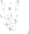
Figure 4 shows a schematic drawing of layout arrangement of a produced water separation operation including a velocity monitor according to some embodiments of the disclosure. -
Figure 5 shows a schematic drawing of layout arrangement of a produced water separation operation including multiple mixers and multiple inline camera bubble monitors according to some embodiments of the disclosure. -
Figure 6A shows a perspective view of a static mixer according to some embodiments of the disclosure. -
Figures 6B and 6C show various mixer plates having differing sizes and shapes according to some embodiments of the disclosure. -
Figure 7 shows an iris-diaphragm type variable valve of a dynamic mixer at various stages of opening and closing according to some embodiments of the disclosure. - In the following description, numerous details are set forth to provide an understanding of the present disclosure. It will be understood by those skilled in the art, however, that the embodiments of the present disclosure may be practiced without these details and that numerous variations or modifications from the described embodiments may be possible.
- In the specification and appended claims: the terms "connect", "connection", "connected", "in connection with", and "connecting" are used to mean "in direct connection with" or "in connection with via one or more elements"; and the term "set" is used to mean "one element" or "more than one element". Further, the terms "couple", "coupling", "coupled", "coupled together", and "coupled with" are used to mean "directly coupled together" or "coupled together via one or more elements". As used herein, the terms "up" and "down", "upper" and "lower", "upwardly" and downwardly", "above" and "below"; and other like terms indicating relative positions above or below a given point or element are used in this description to more clearly describe some embodiments of the disclosure. Similarly, the terms "upstream" and "downstream" are used in this description to indicate relative positions along a path of fluid flow through an element.
- The device and methods of the present disclosure have been developed to provide better control and improved efficiency of the separation processes of oil entrained in produced water. Due to the presence of the oil together with the produced water, the oil and water can collectively be referred to as a multiphase fluid. Various types of separators may be used to remove the oil from the produced water including oil/gas separators, flotation tanks, hydro cyclones, and degassing tanks.
-
Figure 1 shows an example of one type ofseparator 102, a degassing and flotation tank, sometimes referred to as a compact flotation unit or CFU, that may be used according to some embodiments of the disclosure. TheCFU 102 uses gas flotation and centrifugal forces to separate and remove the oil and other particles from the water phase of the multiphase fluid. The combined degassing andflotation tank 102 includes a cylindrical vertical tank 1, a tangentially arrangedinlet 2 for the produced water phase, at least oneoutlet 3 for gas and oil placed in the upper part of the tank 1, anoutlet 4 for water and an outlet 8 for sludge placed in the lower part of the tank 1, and aninner cylinder 10 forming a flotation and degassing zone between theinner cylinder 10 and the wall of the tank 1 in the upper part of the tank. - The cylindrical vertical tank 1 performs the desired separation of an oil/gas phase from a water phase of the multiphase fluid. In use for water treatment in oil production, remaining oil and gas can be removed from the outgoing water phase of the multiphase fluid providing an effluent with a very low content of hydrocarbons simultaneously with the removal of sand and other particulate materials. The tank 1 is provided with an
inner cylinder 10 placed in the upper part of the tank leaving an open space between theinner cylinder 10 and the top of the tank. Aninlet guide vane 11 may be placed between the tank 1 and theinner cylinder 10 leaving an open space between theinlet guide vane 11 and theinner cylinder 10 and a horizontalcircular plate 12 in the lower portion of the tank 1, leaving a passage for water between theplate 12 and the tank 1. Theinner cylinder 10 is arranged so that passage of oil, gas, and water is allowed over the top of the cylinder. - The flotation of oil drops is facilitated by the simultaneous rising of gas bubbles. Further, the
inlet guide vane 11 causes the incoming water to flow spirally upward while the tangential inlet causes the incoming water to rotate in the tank 1, creating a centrifugal force which forces the lighter oil drops towards the center of the tank 1 until theinner cylinder 10 is met. There, oil bubbles and gas bubbles will coalesce and rise due to their lower density than the surrounding water. The oil and gas is then removed via anoutlet 3 for oil and gas. - Additional gas, referred to herein at some places as flotation gas, may be injected into the produced water phase of the multiphase fluid before entering into the
CFU 102 to improve separation and provide additional rising gas bubbles in the tank. - A produced water separation system or
operation 100 according to some embodiments of the disclosure is now described with additional reference to the schematic drawing ofFigure 2 . Beginning the description with upstream components, aproduction fluid source 106 is in fluid communication with thefirst conduit 107 so as to supply the multiphase fluid thereto. - The multiphase fluid flows into the upstream end of the
first conduit 107, and out through the downstream end of thefirst conduit 107 into a first inlet of themixer 108, which is in fluid communication withfirst conduit 107. Aflotation gas source 104, such as an external gas source or gas recycled from the top of the vessel 1, is in fluid communication with a second inlet of themixer 108 and feeds throughoptional gas valve 129 a flotation gas, such as nitrogen or fuel gas, to the second inlet of themixer 108. Themixer 108 serves to mix the inflowing flotation gas with the inflowing multiphase fluid, and provides output of the multiphase fluid as enhanced (mixed) with the flotation gas through an optional externaladjustable valve 114 and into an upstream end of thesecond conduit 109 in fluid communication with the outlet of themixer 108. - As should be appreciated, the mixing of the flotation gas with the multiphase fluid by the
mixer 108 results in formation of bubbles of the flotation gas within the multiphase fluid. The enhanced multiphase fluid flows into the upstream end of thesecond conduit 109, through aninline camera module 110, and out through the downstream end of thesecond conduit 109 into theinlet 2 of theCFU 102. This mixture of gas and oily water then rises to top of theCFU 102 as it enters the tank 1, enhancing separation. After separation, the oil and gas phases may be removed from theCFU 102 via the oil andgas outlet 3 and flow throughvalve 120, and the water phase may be removed from theCFU 102 via thewater outlet 4 and flow throughvalve 122. - Gas bubble size distribution within the enhanced multiphase fluid may be influential for separation efficiency of a
CFU 102. Bubbles that may be too small, e.g. less than 90-110 microns (e.g. 100 microns), may in some cases not reach the surface of the fluid within theCFR 102 to be removed through theoutlet 3. Oil covered small scale bubbles will then exit through theclean water outlet 4. Bubbles that may be too large, e.g. more than 500 microns, may have an issue in that they may have a low flotation potential. The gas bubble size distribution may be dependent on the chemistry of the water, but the Inventors have found it to be closely related to and influenced by the pressure drop generated by thegas mixer 108 which mixes the flotation gas into the produced water. The present disclosure aims to provide technology for monitoring and controlling the bubble size distribution in the enhanced multiphase fluid entering theCFU 102. -
Current mixers 108, such as shown inFigures 6A-7 , have a pressure drop according to the multiphase fluid as it passes through, and this pressure drop varies in the short term and during field life, potentially resulting in varying and non-optimum mixing and process efficiency. When the produced multiphase fluid flow rate to theCFU 102 changes, either increasing or decreasing, the fluid velocity through a current mixer can change due to various reasons, resulting in more or less turbulence and consequently resulting in the formation of smaller or larger gas bubbles in the multiphase fluid. For efficient oil removal, a particularly useful bubble size window exists, but the actual bubble size might fall outside of this range by having a fixed geometry mixer plate or otherwise static gas mixer. - Introduction of a dynamic mixer (capable of maintaining a desired pressure drop regardless of fluid flow rate) provided with a monitoring system or bubble control system provides the ability to maintain the majority of the gas bubbles above a first threshold value (e.g. above 100 microns) and below a second threshold value (e.g. below 500 microns) -- that is, within the desired gas bubble size window -- regardless of the changes to the produced multiphase fluid flow rate into the CFU. These thresholds are set so as to enable separation of a majority of the oil from the enhanced multiphase liquid, and thus the flowing of a majority of the oil phase from the
oil outlet 3. Indeed, the use of the dynamic mixer increases the percentage of oil separation achieved by theCFU 102 over what would be separated without the adjustment capability provided by the dynamic mixer. - Further details of the
system 100 and operation thereof will be given, but first it should be understood that here, thecamera module 110 and controller 112 (described below) form and thus may collectively be referred to as abubble control system 199, and that themixer 108 andoptional valves mixing system 198. - A
controller 112, such as a computer, microcontroller, system on a chip, microprocessor, programmable logic array, or field programmable gate array, is coupled to either (or both of) themixer 108 and the optionaladjustable valve 114, as well as to thecamera module 110. - The
camera module 110 includes a high speed camera that captures images of the bubbles as the enhanced multiphase fluid flows through thesecond conduit 109, and thecontroller 112 operates and monitors output of thecamera 110. In monitoring output of thecamera 110, thecontroller 112 performs image processing, so as to enable online, inline, real-time, continuous monitoring and estimation of bubble size distribution of dispersed flotation gas in the enhanced multiphase fluid flowing throughsecond conduit 109. Thus, thecontroller 112 is able to determine whether the bubble size distribution is within a desired range. - So as to provide hardware for changing and/or controlling the bubble size distribution, the
mixer 108 may be a dynamic mixer capable of varying the size and/or shape of the opening or the position of a valve at its outlet under control of thecontroller 112. In some cases, themixer 108 may instead have a fixed size and shape opening at its outlet, but anadjustable valve 114 under control of thecontroller 112 may be placed between themixer 108 andconduit 109, between sections of theconduit 109, or within theconduit 109. In still other cases, themixer 108 may be a dynamic mixer and thevariable valve 114 may also be present. -
Figures 6B and 6C show differentfixed plates 130a-130d for themixer 108 in the case where the mixer has a fixed size and shape opening at its outlet, with each plate having a different size and shape opening 131a-131d through which the enhanced multiphase fluid flows. - Where the
mixer 108 is a dynamic mixer, it could include any suitable restriction at its outlet causing a pressure drop; for example, a variable area orifice plate valve, a butterfly valve, a specially designed variable cage valve, or equivalent technology mixing the dispersed gas in the fluid. A dynamic mixer may also include an iris-diaphragm typevariable valve 130e-130f as shown inFigure 7 , a valve having two or more plate sizes that can be changed, or other dynamic valve types where the size and/or shape of the opening through which the fluid flows may be altered. - Therefore, the use of the
controller 112 with thecamera module 110 provides a feedback loop, and thecontroller 112 may change thevalve opening 131e-131f in real-time conditions or nearly real-time conditions based on the feedback loop so as to maintain the bubble size distribution within the desired range. - In some cases, the
controller 112 may control the bubble size distribution produced at the outlet of themixer 108 by controlling the rate of flow of flotation gas from thegas source 104 into themixer 108. Thus, for example, thecontroller 112 may control the valve 129 (also referred to as a flotation gas source control) so as to alter the flow rate of gas from thegas source 104 as a function of the determination and monitoring of the bubble size distribution, to thereby maintain the bubble size distribution within a desired range. The control of the rate of flow of flotation gas may be performed in the absence of other control of the mixing system (i.e. may be performed with astatic mixer 108 and without the presence of the valve 114), or may be performed in addition to the control of a dynamic mixer and/or control ofvalve 114. Adjustment of thevalve 129 may also serve to provide adjustment of the pressure at which the flotation gas enters the second inlet of themixer 108. - Monitoring the size of gas bubbles directly in the fashion described above may be complex and expensive. The Inventors have, however, found that a desired bubble size window or range may be linked to a simple pressure drop across a fixed or
dynamic mixer 108. Indeed, it is now believed that the oil removal efficiency of theCFU 102 is dependent on the pressure drop across theupstream mixer 108. Thus, there is a desired pressure drop value corresponding to the gas distribution size window desired to improve efficiency. This may be accomplished by various methods. One method, as previously discussed, includes changing the size of a restriction plate in themixer 108 or in an outlet valve of themixer 108.Figures 6B and 6C shows examples ofrestriction plates 130a-130d having various shapes and sizes. Another method, as will be described below, includes utilizing thevalve 114 to adjust the pressure drop. The resulting process efficiency using thevalve 114 and astatic mixer 108 in combination is also equal for the same pressure drop. Thus, astatic mixer 108 andvalve 114 may be used in combination to create similar results as a dynamic mixer, helping keep the bubble size distribution within the desired range regardless of a flow rate of the multiphase fluid through thefirst conduit 107. - In addition, the Inventors have found that the bubble size distribution is a function of the pressure drop. Thus, as explained above, the pressure drop across the
mixer 108 may be monitored as a function of the position of the outlet valve inmixer 108, size or shape of an orifice within the outlet valve inmixer 108, or a size or shape of an orifice within arestriction plate 130a-130f within themixer 108. The pressure drop may also be monitored as a function of position of thevalve 114, size or shape of an orifice within thevalve 114, or size or shape of an orifice within arestriction plate 130a-130f within thevalve 114. The position of the outlet valve inmixer 108, size or shape of an orifice within the outlet valve inmixer 108, or a size or shape of an orifice within arestriction plate 130a-130f within themixer 108 may then be adjusted or controlled as a function of the monitored pressure drop. Likewise, the position of thevalve 114, size or shape of an orifice within thevalve 114, or size or shape of an orifice within arestriction plate 130a-130f within thevalve 114 may be adjusted or controlled as a function of the monitored pressure drop. This adjustment or control may be performed manually in the case where themixer 108 is static, or in the case where thevalve 114 is static. This adjustment or control may be performed under control of thecontroller 112 in the case where themixer 108 is dynamic, or in the case where thevalve 114 is dynamic. -
Figure 3 shows a schematic drawing of layout arrangement of a produced water separation system 100' including a differential pressure monitor 125 according to some embodiments of the disclosure. Other components are similar to or the same as described above and need no further discussion. - The differential pressure monitor 125 is of a suitable type and kind, and may be comprised of pressure sensors at the first inlet and at the outlet of the mixer 108 (or the outlet of the valve 114). The
controller 112 may compare the readings of the pressure sensors of the differential pressure monitor 125 so as to determine the pressure drop across themixer 108. Thecontroller 112 may then control themixer 108 and/orvalve 114 as a function of the pressure drop so as to maintain the pressure drop within a desired range that maintains the bubble size distribution within a desired range. - Measured or estimated fluid velocity or other empirical correlations could be used as feedback to the
controller 112 for use in controlling themixer 108 and/orvalve 114 so as to maintain bubble size distribution within a desired range. For example, as shown inFigure 4 , thesystem 100" may include fluid velocity orfluid flow meters 126 at the first inlet and/or at the outlet of the mixer 108 (or the outlet of the valve 114), such as to provide for estimation of the velocity of the multiphase fluid in thefirst conduit 107 and the enhanced multiphase fluid in thesecond conduit 109. Thecontroller 112 may compare the readings of the velocity or flowmeters 126 so as to determine the flow rate or fluid velocity increase across themixer 108. Thecontroller 112 may then control themixer 108 and/orvalve 114 as a function of the flow rate or velocity drop so as to maintain the flow rate or velocity increase within a desired range that maintains the bubble size distribution within a desired range - Although in the configurations described thus far a
single mixer 108,valve 114,gas valve 129, andcamera module 110 have been shown, there may be multiple of each in some applications. For example, in theconfiguration 100"' shown inFIG. 5 , there are twoinline mixers optional valve camera module 110a is positioned along theconduit 109a between themixers camera module 110b is positioned along theconduit 109b between themixer 108b and theCFU 102. Thegas source 104 supplies gas togas valves mixers controller 112 as described above. - The
mixers dynamic mixers mixer dynamic mixer optional valves dynamic mixers valves camera modules - It should be apparent that with the previously described embodiments in
Figures 3-4 ,multiple mixers 114,valves 108,gas valves 129,differential pressure sensors 125, andvelocity flow meters 126, may be used similarly to as shown inFIG. 5 . Also, it should be apparent that different potentialbubble control system more camera modules 110 may be used together with one or moredifferential pressure sensors 125 in a single application so as to provide for additional data for use by thecontroller 112 in controlling themixers 114,valves 108, andgas valves 129. - Other suitable methods and technologies for measuring properties of the enhanced multiphase fluid and size of the bubbles may be used as well. For example, acoustic monitoring techniques may be used on the enhanced multiphase fluid as a way to estimate the size of the flotation gas bubbles, and the controller may use this information in controlling the mixer, and/or valve, and/or gas valve.
- In some embodiments, the flotation gas can be released from the liquid water phase by pressure drop added downstream of the
CFU 102. For example, with respect to the removal of dissolved flotation gas from the liquid water phase, the liquid water phase may be configured flow out thewater outlet 4 in the cylindrical vertical tank 1 and into a conduit, vessel, or other fluid bearing structure having a diameter wider than that of theoutlet 4 so as to cause the liquid water phase to undergo a drop in fluid pressure. This drop in fluid pressure may result in degasification of the liquid water phase, and thus flotation gas that has dissolved in the liquid water phase may exit the liquid water phase. - The
systems systems controller 112 may be the controller of the CFU as well. This helps enable optimization of process efficiency based on bubble size, regardless of changing fluid flow rates in thesystem - Although the preceding description has been described herein with reference to particular means, materials and embodiments, it is not intended to be limited to the particulars disclosed herein; rather, it extends to functionally equivalent structures, methods, and uses, such as are within the scope of the appended claims.
Claims (9)
- A system comprising:a first conduit (107) for flowing a multiphase fluid;a flotation gas source (104);a mixing system (198) having a first inlet in fluid communication with a downstream end of the first conduit (107), a second inlet in fluid communication with the flotation gas source (104), and an outlet, the mixing system configured to mix the multiphase fluid flowing from the downstream end of the first conduit (107) with flotation gas from the flotation gas source (104) so as to produce at the outlet an enhanced multiphase fluid having bubbles of the flotation gas therein;a second conduit (109) having an upstream end in fluid communication with the outlet of the mixing system (198);a bubble control system (199) associated with the second conduit (109) and configured to:determine one of a fluid velocity or flow rate of the multiphase fluid in the first conduit (107) and the enhanced multiphase fluid in the second conduit (109) to determine a fluid velocity or flowrate increase across the mixing system (198); andcharacterised in that it is further configured to control the mixing system (198) as a function of the flow rate or velocity drop so as to maintain the velocity or flowrate increase within a desired range that maintains the bubble size distribution of bubbles within the enhanced multiphase fluid within a desired range.
- The system of claim 1 , wherein the mixing system (198) comprises a static mixer (108) and wherein maintaining the velocity or flow rate increase of the multiphase fluid within the desired range comprises adjusting an outlet valve (114) associated with the static mixer (108) to adjust the velocity or flow rate of the enhanced multiphase fluid as it flows therethrough.
- The system of claim 2, wherein the adjustable outlet valve (114) is one of a variable area orifice plate valve, a butterfly valve, a variable cage valve, an iris-diaphragm type variable valve, or a valve having a changeable restriction plate therein.
- The system of claim 1, wherein the mixing system (198) includes a flotation gas source control (129) for the flotation gas source (104) and wherein the bubble control system (199) controls the mixing system (198) by communicating with the flotation gas source control (129) so as to change a flow rate of the flotation gas source (104).
- The system of claim 3, wherein the bubble control system (199) comprises:
a controller (112) configured to receive measurements from fluid velocity or flow rate meters (126) in the first conduit (107) and the second conduit (109) to determine the velocity or flow rate increase and to control the mixer (108) and/or valve to maintain the increase within the desired range. - The system of any preceding claim, further comprising a separator (102) having an inlet in fluid communication with a downstream end of the second conduit (109), and an oil outlet (3) through which at least a portion of an oil phase of the enhanced multiphase fluid may be permitted to flow; and wherein the desired range of the bubble size distribution is sufficient so as to permit flowing of a majority of the oil phase through the oil outlet (3).
- A method comprising:mixing a multiphase fluid with a flotation gas, according to at least one operating condition, so as to produce an enhanced multiphase fluid having bubbles of the flotation gas therein;monitoring the increase of the fluid velocity or the flow rate of the multiphase fluid across a mixing system for mixing the multiphase fluid with the flotation gas; characterised bymaintaining the velocity or flowrate increase of the multiphase fluid within a desired range so as to maintain a distribution of bubbles within the enhanced multiphase fluid within a desired range.
- The method of claim 7, wherein the mixing is performed using a static mixer (108) and wherein maintaining the velocity or flow rate increase of the multiphase fluid within the desired range comprises adjusting an outlet valve (114) associated with the static mixer (108) to adjust the velocity or flow rate of the enhanced multiphase fluid as it flows therethrough.
- The method of claim 7, wherein the mixing is performed using a static mixer (108), wherein maintaining the velocity or flow rate increase of the multiphase fluid within the desired range comprises adjusting the flow rate of the flotation gas during the mixing to adjust the velocity or flow rate of the enhanced multiphase fluid.
Applications Claiming Priority (2)
| Application Number | Priority Date | Filing Date | Title |
|---|---|---|---|
| US201562210775P | 2015-08-27 | 2015-08-27 | |
| PCT/US2016/048825 WO2017035422A1 (en) | 2015-08-27 | 2016-08-26 | Bubble size monitoring and control |
Publications (3)
| Publication Number | Publication Date |
|---|---|
| EP3341331A1 EP3341331A1 (en) | 2018-07-04 |
| EP3341331A4 EP3341331A4 (en) | 2019-05-01 |
| EP3341331B1 true EP3341331B1 (en) | 2020-06-17 |
Family
ID=58100941
Family Applications (1)
| Application Number | Title | Priority Date | Filing Date |
|---|---|---|---|
| EP16840177.6A Active EP3341331B1 (en) | 2015-08-27 | 2016-08-26 | Bubble size monitoring and control |
Country Status (8)
| Country | Link |
|---|---|
| US (2) | US20180244539A1 (en) |
| EP (1) | EP3341331B1 (en) |
| JP (1) | JP7034903B2 (en) |
| KR (1) | KR20180035236A (en) |
| CN (1) | CN107949543A (en) |
| DK (1) | DK3341331T3 (en) |
| SA (1) | SA518391019B1 (en) |
| WO (1) | WO2017035422A1 (en) |
Families Citing this family (12)
| Publication number | Priority date | Publication date | Assignee | Title |
|---|---|---|---|---|
| EP3341331B1 (en) | 2015-08-27 | 2020-06-17 | Services Petroliers Schlumberger | Bubble size monitoring and control |
| WO2019156686A1 (en) * | 2018-02-12 | 2019-08-15 | Hewlett-Packard Development Company, L.P. | Microfluidic flow sensor |
| WO2021171502A1 (en) * | 2020-02-27 | 2021-09-02 | ヤマハ発動機株式会社 | Marine trash collection device |
| TWI718963B (en) * | 2020-06-11 | 2021-02-11 | 威光自動化科技股份有限公司 | Air bubble detection device for preventing air plugs in liquid pipe |
| CN113198619B (en) * | 2021-05-18 | 2022-02-11 | 中南大学 | Coarse particle flotation equipment and method adopting rotational flow and damping coupled fluidization |
| US12146779B2 (en) | 2021-09-22 | 2024-11-19 | Saudi Arabian Oil Company | Method and system for separating and analyzing multiphase immiscible fluid mixtures |
| US11833445B2 (en) | 2021-09-22 | 2023-12-05 | Saudi Arabian Oil Company | Method and device for separating and measuring multiphase immiscible fluid mixtures using an improved analytical cell |
| US11761945B2 (en) | 2021-09-22 | 2023-09-19 | Saudi Arabian Oil Company | Water analysis unit of a system for separating and analyzing a multiphase immiscible fluid mixture and corresponding method |
| US11833449B2 (en) | 2021-09-22 | 2023-12-05 | Saudi Arabian Oil Company | Method and device for separating and measuring multiphase immiscible fluid mixtures |
| US20240173681A1 (en) * | 2022-11-28 | 2024-05-30 | Koflo Corporation | Baffle Elements and Static Mixers Including Baffles Elements |
| CN116989504A (en) * | 2023-08-30 | 2023-11-03 | 青岛海尔空调器有限总公司 | A direct-flow gas-liquid separator and air conditioner |
| WO2026050319A1 (en) * | 2024-08-29 | 2026-03-05 | Cameron International Corporation | Inline separator with gas flashing |
Family Cites Families (21)
| Publication number | Priority date | Publication date | Assignee | Title |
|---|---|---|---|---|
| US4031006A (en) | 1976-03-12 | 1977-06-21 | Swift And Company Limited | Vortex coagulation means and method for wastewater clarification |
| US5080802A (en) * | 1990-05-09 | 1992-01-14 | Cairo Jr John A | Induced gas liquid coalescer and flotation separator |
| US5275732A (en) * | 1990-07-03 | 1994-01-04 | International Environmental Systems, Inc., Usa | Combined coarse and fine bubble separation system |
| US5326468A (en) * | 1992-03-02 | 1994-07-05 | Cox Dale W | Water remediation and purification method and apparatus |
| GB9809016D0 (en) * | 1998-04-29 | 1998-06-24 | Wrc Plc | Method for monitoring bubbles in liquid |
| US6408679B1 (en) * | 2000-02-04 | 2002-06-25 | The United States Of America As Represented By The Administrator Of The National Aeronautics And Space Administration | Bubble measuring instrument and method |
| EP1208897A1 (en) * | 2000-11-21 | 2002-05-29 | Epcon Norge AS | Combined degassing and flotation tank |
| US7638042B2 (en) * | 2002-02-15 | 2009-12-29 | 3M Innovative Properties Company | System for monitoring the performance of fluid treatment cartridges |
| DE10216643A1 (en) * | 2002-04-15 | 2003-10-30 | Fraunhofer Ges Forschung | Flotation plant for wastewater treatment and a method for operating such a plant |
| US6964740B2 (en) * | 2002-06-25 | 2005-11-15 | Dwain E. Morse | System and method of gas energy management for particle flotation and separation |
| CA2462740C (en) | 2004-03-31 | 2015-03-24 | Minnovex Technologies Inc. | Method for froth flotation |
| US7426852B1 (en) * | 2004-04-26 | 2008-09-23 | Expro Meters, Inc. | Submersible meter for measuring a parameter of gas hold-up of a fluid |
| CA2485873A1 (en) | 2004-10-22 | 2006-04-22 | Peter Douglas Jack | Apparatus and method for blending or infusing one fluid into another fluid |
| JP2006334556A (en) * | 2005-06-06 | 2006-12-14 | Hitachi Housetec Co Ltd | Fine bubble generation nozzle and fine bubble generation bath |
| JP4151681B2 (en) * | 2005-07-19 | 2008-09-17 | 株式会社日立製作所 | Fine bubble generating apparatus and method |
| US20080112257A1 (en) * | 2006-11-10 | 2008-05-15 | Masatoshi Masuda | Mixing device for tub |
| US20140016433A1 (en) * | 2009-04-23 | 2014-01-16 | Peter Douglas Jack | Method and apparatus for generating micro bubbles in a fluid flow |
| US9115006B2 (en) * | 2010-01-14 | 2015-08-25 | Spintek Filtration, Inc. | Gas bubble generation for coalescing |
| DK177387B1 (en) * | 2010-04-12 | 2013-03-04 | Schlumberger Norge As | A flotation unit for purifying water, such as a CFU (Compact Flotation Unit) |
| EP3045228B8 (en) | 2015-01-13 | 2018-01-24 | Roland Damann | Microflotation system with an expansion valve arrangement and method for operating a microflotation system |
| EP3341331B1 (en) | 2015-08-27 | 2020-06-17 | Services Petroliers Schlumberger | Bubble size monitoring and control |
-
2016
- 2016-08-26 EP EP16840177.6A patent/EP3341331B1/en active Active
- 2016-08-26 KR KR1020187005752A patent/KR20180035236A/en not_active Ceased
- 2016-08-26 US US15/751,021 patent/US20180244539A1/en not_active Abandoned
- 2016-08-26 JP JP2018510917A patent/JP7034903B2/en active Active
- 2016-08-26 CN CN201680049575.XA patent/CN107949543A/en active Pending
- 2016-08-26 DK DK16840177.6T patent/DK3341331T3/en active
- 2016-08-26 WO PCT/US2016/048825 patent/WO2017035422A1/en not_active Ceased
-
2018
- 2018-02-26 SA SA518391019A patent/SA518391019B1/en unknown
-
2022
- 2022-08-17 US US17/820,438 patent/US12559389B2/en active Active
Non-Patent Citations (1)
| Title |
|---|
| None * |
Also Published As
| Publication number | Publication date |
|---|---|
| WO2017035422A1 (en) | 2017-03-02 |
| CN107949543A (en) | 2018-04-20 |
| JP7034903B2 (en) | 2022-03-14 |
| US20180244539A1 (en) | 2018-08-30 |
| US20220396502A1 (en) | 2022-12-15 |
| DK3341331T3 (en) | 2020-09-21 |
| JP2018533463A (en) | 2018-11-15 |
| SA518391019B1 (en) | 2021-07-07 |
| EP3341331A4 (en) | 2019-05-01 |
| KR20180035236A (en) | 2018-04-05 |
| US12559389B2 (en) | 2026-02-24 |
| EP3341331A1 (en) | 2018-07-04 |
Similar Documents
| Publication | Publication Date | Title |
|---|---|---|
| US12559389B2 (en) | Bubble size monitoring and control | |
| JP2018533463A5 (en) | ||
| US9714561B2 (en) | Separator and method of separation | |
| EP3116621B1 (en) | Split flow pipe separator with sand traps comprising a sand cyclone and process using it | |
| EP3185978B1 (en) | Emulsion extraction from an oil/water separator and processing by water dilution from the same separator | |
| CA3090353C (en) | Fluid treatment separator and a system and method of treating fluid | |
| JP6236347B2 (en) | Separation apparatus and separation method | |
| US7854849B2 (en) | Compact multiphase inline bulk water separation method and system for hydrocarbon production | |
| US20120152122A1 (en) | Water separation systems and methods | |
| US8246843B2 (en) | Process and device for the separation of oil/water mixtures | |
| Shaiek et al. | Spoolsep for subsea produced water separation-experimental results | |
| Famisa | HYSYS Modelling of a Horizontal Three-Phase Subsea Separator | |
| AU2011345334A1 (en) | Water separation systems and methods | |
| KR20170112266A (en) | Multi Phase Fluid Mixing Valve | |
| Famisa | SPECIALIZATION PROJECT 2015 |
Legal Events
| Date | Code | Title | Description |
|---|---|---|---|
| STAA | Information on the status of an ep patent application or granted ep patent |
Free format text: STATUS: THE INTERNATIONAL PUBLICATION HAS BEEN MADE |
|
| PUAI | Public reference made under article 153(3) epc to a published international application that has entered the european phase |
Free format text: ORIGINAL CODE: 0009012 |
|
| STAA | Information on the status of an ep patent application or granted ep patent |
Free format text: STATUS: REQUEST FOR EXAMINATION WAS MADE |
|
| 17P | Request for examination filed |
Effective date: 20180313 |
|
| AK | Designated contracting states |
Kind code of ref document: A1 Designated state(s): AL AT BE BG CH CY CZ DE DK EE ES FI FR GB GR HR HU IE IS IT LI LT LU LV MC MK MT NL NO PL PT RO RS SE SI SK SM TR |
|
| AX | Request for extension of the european patent |
Extension state: BA ME |
|
| DAV | Request for validation of the european patent (deleted) | ||
| DAX | Request for extension of the european patent (deleted) | ||
| A4 | Supplementary search report drawn up and despatched |
Effective date: 20190402 |
|
| RIC1 | Information provided on ipc code assigned before grant |
Ipc: C02F 1/24 20060101AFI20190327BHEP Ipc: C02F 1/20 20060101ALI20190327BHEP |
|
| GRAP | Despatch of communication of intention to grant a patent |
Free format text: ORIGINAL CODE: EPIDOSNIGR1 |
|
| STAA | Information on the status of an ep patent application or granted ep patent |
Free format text: STATUS: GRANT OF PATENT IS INTENDED |
|
| INTG | Intention to grant announced |
Effective date: 20200115 |
|
| GRAS | Grant fee paid |
Free format text: ORIGINAL CODE: EPIDOSNIGR3 |
|
| GRAA | (expected) grant |
Free format text: ORIGINAL CODE: 0009210 |
|
| STAA | Information on the status of an ep patent application or granted ep patent |
Free format text: STATUS: THE PATENT HAS BEEN GRANTED |
|
| AK | Designated contracting states |
Kind code of ref document: B1 Designated state(s): AL AT BE BG CH CY CZ DE DK EE ES FI FR GB GR HR HU IE IS IT LI LT LU LV MC MK MT NL NO PL PT RO RS SE SI SK SM TR |
|
| REG | Reference to a national code |
Ref country code: GB Ref legal event code: FG4D |
|
| REG | Reference to a national code |
Ref country code: CH Ref legal event code: EP |
|
| REG | Reference to a national code |
Ref country code: DE Ref legal event code: R096 Ref document number: 602016038450 Country of ref document: DE |
|
| REG | Reference to a national code |
Ref country code: IE Ref legal event code: FG4D |
|
| REG | Reference to a national code |
Ref country code: AT Ref legal event code: REF Ref document number: 1281084 Country of ref document: AT Kind code of ref document: T Effective date: 20200715 |
|
| REG | Reference to a national code |
Ref country code: DK Ref legal event code: T3 Effective date: 20200917 |
|
| REG | Reference to a national code |
Ref country code: NL Ref legal event code: FP |
|
| PG25 | Lapsed in a contracting state [announced via postgrant information from national office to epo] |
Ref country code: LT Free format text: LAPSE BECAUSE OF FAILURE TO SUBMIT A TRANSLATION OF THE DESCRIPTION OR TO PAY THE FEE WITHIN THE PRESCRIBED TIME-LIMIT Effective date: 20200617 Ref country code: SE Free format text: LAPSE BECAUSE OF FAILURE TO SUBMIT A TRANSLATION OF THE DESCRIPTION OR TO PAY THE FEE WITHIN THE PRESCRIBED TIME-LIMIT Effective date: 20200617 Ref country code: GR Free format text: LAPSE BECAUSE OF FAILURE TO SUBMIT A TRANSLATION OF THE DESCRIPTION OR TO PAY THE FEE WITHIN THE PRESCRIBED TIME-LIMIT Effective date: 20200918 Ref country code: FI Free format text: LAPSE BECAUSE OF FAILURE TO SUBMIT A TRANSLATION OF THE DESCRIPTION OR TO PAY THE FEE WITHIN THE PRESCRIBED TIME-LIMIT Effective date: 20200617 |
|
| REG | Reference to a national code |
Ref country code: NO Ref legal event code: T2 Effective date: 20200617 |
|
| REG | Reference to a national code |
Ref country code: LT Ref legal event code: MG4D |
|
| PG25 | Lapsed in a contracting state [announced via postgrant information from national office to epo] |
Ref country code: RS Free format text: LAPSE BECAUSE OF FAILURE TO SUBMIT A TRANSLATION OF THE DESCRIPTION OR TO PAY THE FEE WITHIN THE PRESCRIBED TIME-LIMIT Effective date: 20200617 Ref country code: LV Free format text: LAPSE BECAUSE OF FAILURE TO SUBMIT A TRANSLATION OF THE DESCRIPTION OR TO PAY THE FEE WITHIN THE PRESCRIBED TIME-LIMIT Effective date: 20200617 Ref country code: HR Free format text: LAPSE BECAUSE OF FAILURE TO SUBMIT A TRANSLATION OF THE DESCRIPTION OR TO PAY THE FEE WITHIN THE PRESCRIBED TIME-LIMIT Effective date: 20200617 Ref country code: BG Free format text: LAPSE BECAUSE OF FAILURE TO SUBMIT A TRANSLATION OF THE DESCRIPTION OR TO PAY THE FEE WITHIN THE PRESCRIBED TIME-LIMIT Effective date: 20200917 |
|
| REG | Reference to a national code |
Ref country code: AT Ref legal event code: MK05 Ref document number: 1281084 Country of ref document: AT Kind code of ref document: T Effective date: 20200617 |
|
| PG25 | Lapsed in a contracting state [announced via postgrant information from national office to epo] |
Ref country code: AL Free format text: LAPSE BECAUSE OF FAILURE TO SUBMIT A TRANSLATION OF THE DESCRIPTION OR TO PAY THE FEE WITHIN THE PRESCRIBED TIME-LIMIT Effective date: 20200617 |
|
| PG25 | Lapsed in a contracting state [announced via postgrant information from national office to epo] |
Ref country code: CZ Free format text: LAPSE BECAUSE OF FAILURE TO SUBMIT A TRANSLATION OF THE DESCRIPTION OR TO PAY THE FEE WITHIN THE PRESCRIBED TIME-LIMIT Effective date: 20200617 Ref country code: EE Free format text: LAPSE BECAUSE OF FAILURE TO SUBMIT A TRANSLATION OF THE DESCRIPTION OR TO PAY THE FEE WITHIN THE PRESCRIBED TIME-LIMIT Effective date: 20200617 Ref country code: SM Free format text: LAPSE BECAUSE OF FAILURE TO SUBMIT A TRANSLATION OF THE DESCRIPTION OR TO PAY THE FEE WITHIN THE PRESCRIBED TIME-LIMIT Effective date: 20200617 Ref country code: RO Free format text: LAPSE BECAUSE OF FAILURE TO SUBMIT A TRANSLATION OF THE DESCRIPTION OR TO PAY THE FEE WITHIN THE PRESCRIBED TIME-LIMIT Effective date: 20200617 Ref country code: PT Free format text: LAPSE BECAUSE OF FAILURE TO SUBMIT A TRANSLATION OF THE DESCRIPTION OR TO PAY THE FEE WITHIN THE PRESCRIBED TIME-LIMIT Effective date: 20201019 Ref country code: ES Free format text: LAPSE BECAUSE OF FAILURE TO SUBMIT A TRANSLATION OF THE DESCRIPTION OR TO PAY THE FEE WITHIN THE PRESCRIBED TIME-LIMIT Effective date: 20200617 Ref country code: AT Free format text: LAPSE BECAUSE OF FAILURE TO SUBMIT A TRANSLATION OF THE DESCRIPTION OR TO PAY THE FEE WITHIN THE PRESCRIBED TIME-LIMIT Effective date: 20200617 |
|
| PG25 | Lapsed in a contracting state [announced via postgrant information from national office to epo] |
Ref country code: IS Free format text: LAPSE BECAUSE OF FAILURE TO SUBMIT A TRANSLATION OF THE DESCRIPTION OR TO PAY THE FEE WITHIN THE PRESCRIBED TIME-LIMIT Effective date: 20201017 Ref country code: SK Free format text: LAPSE BECAUSE OF FAILURE TO SUBMIT A TRANSLATION OF THE DESCRIPTION OR TO PAY THE FEE WITHIN THE PRESCRIBED TIME-LIMIT Effective date: 20200617 Ref country code: PL Free format text: LAPSE BECAUSE OF FAILURE TO SUBMIT A TRANSLATION OF THE DESCRIPTION OR TO PAY THE FEE WITHIN THE PRESCRIBED TIME-LIMIT Effective date: 20200617 |
|
| REG | Reference to a national code |
Ref country code: DE Ref legal event code: R119 Ref document number: 602016038450 Country of ref document: DE |
|
| PG25 | Lapsed in a contracting state [announced via postgrant information from national office to epo] |
Ref country code: MC Free format text: LAPSE BECAUSE OF FAILURE TO SUBMIT A TRANSLATION OF THE DESCRIPTION OR TO PAY THE FEE WITHIN THE PRESCRIBED TIME-LIMIT Effective date: 20200617 |
|
| REG | Reference to a national code |
Ref country code: CH Ref legal event code: PL |
|
| PLBE | No opposition filed within time limit |
Free format text: ORIGINAL CODE: 0009261 |
|
| STAA | Information on the status of an ep patent application or granted ep patent |
Free format text: STATUS: NO OPPOSITION FILED WITHIN TIME LIMIT |
|
| PG25 | Lapsed in a contracting state [announced via postgrant information from national office to epo] |
Ref country code: LU Free format text: LAPSE BECAUSE OF NON-PAYMENT OF DUE FEES Effective date: 20200826 Ref country code: LI Free format text: LAPSE BECAUSE OF NON-PAYMENT OF DUE FEES Effective date: 20200831 Ref country code: CH Free format text: LAPSE BECAUSE OF NON-PAYMENT OF DUE FEES Effective date: 20200831 |
|
| 26N | No opposition filed |
Effective date: 20210318 |
|
| REG | Reference to a national code |
Ref country code: BE Ref legal event code: MM Effective date: 20200831 |
|
| PG25 | Lapsed in a contracting state [announced via postgrant information from national office to epo] |
Ref country code: SI Free format text: LAPSE BECAUSE OF FAILURE TO SUBMIT A TRANSLATION OF THE DESCRIPTION OR TO PAY THE FEE WITHIN THE PRESCRIBED TIME-LIMIT Effective date: 20200617 |
|
| PG25 | Lapsed in a contracting state [announced via postgrant information from national office to epo] |
Ref country code: DE Free format text: LAPSE BECAUSE OF NON-PAYMENT OF DUE FEES Effective date: 20210302 |
|
| PG25 | Lapsed in a contracting state [announced via postgrant information from national office to epo] |
Ref country code: IE Free format text: LAPSE BECAUSE OF NON-PAYMENT OF DUE FEES Effective date: 20200826 Ref country code: BE Free format text: LAPSE BECAUSE OF NON-PAYMENT OF DUE FEES Effective date: 20200831 |
|
| PG25 | Lapsed in a contracting state [announced via postgrant information from national office to epo] |
Ref country code: TR Free format text: LAPSE BECAUSE OF FAILURE TO SUBMIT A TRANSLATION OF THE DESCRIPTION OR TO PAY THE FEE WITHIN THE PRESCRIBED TIME-LIMIT Effective date: 20200617 Ref country code: MT Free format text: LAPSE BECAUSE OF FAILURE TO SUBMIT A TRANSLATION OF THE DESCRIPTION OR TO PAY THE FEE WITHIN THE PRESCRIBED TIME-LIMIT Effective date: 20200617 Ref country code: CY Free format text: LAPSE BECAUSE OF FAILURE TO SUBMIT A TRANSLATION OF THE DESCRIPTION OR TO PAY THE FEE WITHIN THE PRESCRIBED TIME-LIMIT Effective date: 20200617 |
|
| PG25 | Lapsed in a contracting state [announced via postgrant information from national office to epo] |
Ref country code: MK Free format text: LAPSE BECAUSE OF FAILURE TO SUBMIT A TRANSLATION OF THE DESCRIPTION OR TO PAY THE FEE WITHIN THE PRESCRIBED TIME-LIMIT Effective date: 20200617 |
|
| P01 | Opt-out of the competence of the unified patent court (upc) registered |
Effective date: 20231208 |
|
| PGFP | Annual fee paid to national office [announced via postgrant information from national office to epo] |
Ref country code: NL Payment date: 20250704 Year of fee payment: 10 |
|
| PGFP | Annual fee paid to national office [announced via postgrant information from national office to epo] |
Ref country code: DK Payment date: 20250814 Year of fee payment: 10 |
|
| PGFP | Annual fee paid to national office [announced via postgrant information from national office to epo] |
Ref country code: NO Payment date: 20250808 Year of fee payment: 10 |
|
| PGFP | Annual fee paid to national office [announced via postgrant information from national office to epo] |
Ref country code: IT Payment date: 20250722 Year of fee payment: 10 |
|
| PGFP | Annual fee paid to national office [announced via postgrant information from national office to epo] |
Ref country code: GB Payment date: 20250703 Year of fee payment: 10 |
|
| PGFP | Annual fee paid to national office [announced via postgrant information from national office to epo] |
Ref country code: FR Payment date: 20250703 Year of fee payment: 10 |