EP3340658A1 - Hearing device with analog filtering and associated method - Google Patents
Hearing device with analog filtering and associated method Download PDFInfo
- Publication number
- EP3340658A1 EP3340658A1 EP18156397.4A EP18156397A EP3340658A1 EP 3340658 A1 EP3340658 A1 EP 3340658A1 EP 18156397 A EP18156397 A EP 18156397A EP 3340658 A1 EP3340658 A1 EP 3340658A1
- Authority
- EP
- European Patent Office
- Prior art keywords
- audio signal
- preprocessing unit
- noise
- hearing device
- transfer function
- Prior art date
- Legal status (The legal status is an assumption and is not a legal conclusion. Google has not performed a legal analysis and makes no representation as to the accuracy of the status listed.)
- Granted
Links
Images



Classifications
-
- H—ELECTRICITY
- H04—ELECTRIC COMMUNICATION TECHNIQUE
- H04R—LOUDSPEAKERS, MICROPHONES, GRAMOPHONE PICK-UPS OR LIKE ACOUSTIC ELECTROMECHANICAL TRANSDUCERS; ELECTRIC HEARING AIDS; PUBLIC ADDRESS SYSTEMS
- H04R25/00—Electric hearing aids
- H04R25/50—Customised settings for obtaining desired overall acoustical characteristics
-
- H—ELECTRICITY
- H04—ELECTRIC COMMUNICATION TECHNIQUE
- H04R—LOUDSPEAKERS, MICROPHONES, GRAMOPHONE PICK-UPS OR LIKE ACOUSTIC ELECTROMECHANICAL TRANSDUCERS; ELECTRIC HEARING AIDS; PUBLIC ADDRESS SYSTEMS
- H04R2410/00—Microphones
- H04R2410/07—Mechanical or electrical reduction of wind noise generated by wind passing a microphone
-
- H—ELECTRICITY
- H04—ELECTRIC COMMUNICATION TECHNIQUE
- H04R—LOUDSPEAKERS, MICROPHONES, GRAMOPHONE PICK-UPS OR LIKE ACOUSTIC ELECTROMECHANICAL TRANSDUCERS; ELECTRIC HEARING AIDS; PUBLIC ADDRESS SYSTEMS
- H04R25/00—Electric hearing aids
- H04R25/50—Customised settings for obtaining desired overall acoustical characteristics
- H04R25/502—Customised settings for obtaining desired overall acoustical characteristics using analog signal processing
-
- H—ELECTRICITY
- H04—ELECTRIC COMMUNICATION TECHNIQUE
- H04R—LOUDSPEAKERS, MICROPHONES, GRAMOPHONE PICK-UPS OR LIKE ACOUSTIC ELECTROMECHANICAL TRANSDUCERS; ELECTRIC HEARING AIDS; PUBLIC ADDRESS SYSTEMS
- H04R25/00—Electric hearing aids
- H04R25/50—Customised settings for obtaining desired overall acoustical characteristics
- H04R25/505—Customised settings for obtaining desired overall acoustical characteristics using digital signal processing
Definitions
- the present invention relates to a hearing device or hearing aid with analog filtering and associated method.
- the present invention relates to a hearing aid having improved wind noise reduction.
- Wind noise is experienced as very unpleasant by a hearing device user and considerably reduces the userfriendliness of a hearing device.
- Known methods for reducing wind noise in hearing devices include filtering in the digital domain. Further, it is known to reduce the gain of a preamplifier to remove the uncomfortable sound levels. This however is at the expence of normal sound processing basically getting destroyed rendering the hearing device somewhat unusable.
- a hearing device comprising: a microphone for converting audio into an audio signal; a preprocessing unit for analog processing of the audio signal and having an input and an output, wherein the input is connected to an output of the microphone; an A/D converter for converting the processed analog audio signal into a digital audio signal, the A/D converter having an input and an output, wherein the input is connected to the output of the preprocessing unit; and a processing unit for digital processing of A/D converter output, wherein the processing unit is connected to the preprocessing unit.
- the preprocessing unit is configured to apply a first transfer function to the audio signal in a first mode of operation and a second transfer function with a second cutoff frequency to the audio signal in a second mode of operation, depending on a control signal from the processing unit.
- Also disclosed is a method for operating a hearing aid comprising a microphone, a preprocessing unit, an A/D converter, and a processing unit
- the method comprising: applying, in the preprocessing unit, a first transfer function to an audio signal from the microphone; converting the preprocessed audio signal to a digital audio signal; determining one or more noise parameters including a first noise parameter: and applying, in the preprocessing unit, a second transfer function, e.g. with a second cutoff frequency, to the audio signal from the microphone depending on a noise criterion, e.g. a first noise criterion, based on the one or more noise parameters.
- a noise criterion e.g. a first noise criterion
- the method may comprise determining the one or more noise parameters while applying the second transfer function, and applying, in the preprocessing unit, the first transfer function or a third transfer function to the audio signal from the microphone depending on a noise criterion, e.g. a second noise criterion.
- a noise criterion e.g. a second noise criterion.
- the hearing device and method enable a more efficient use of signal processing lives by removing undesired noise at an early stage in the signal processing of the hearing device. Thereby, improved power management is provided.
- the preprocessing unit processes the audio signal from the microphone and has an input and an output.
- the input comprises a first input terminal connected to an output, e.g. a first output terminal, of the microphone.
- the preprocessing unit may comprise one or more control terminals for receiving and/or sending control signal(s) from/to the processing unit.
- the preprocessing unit may comprise a first capacitor circuit with a first capacitance value.
- the first capacitance value may be variable, e.g. the first capacitance value may depend on the control signal from the processing unit.
- the preprocessing unit may comprise a second capacitor or second capacitor circuit having a second capacitance value.
- the second capacitance value may be variable, e.g. the second capacitance value may depend on the control signal from the processing unit.
- a variable first and/or second capacitance circuit may reduce the microphone requirements with regard to DC biasing or drifting.
- a capacitor or capacitor circuit has a first and a second terminal having a capacitance value therebetween.
- the preprocessing unit may comprise a first resistor circuit with a first resistance value.
- the first resistance value may be variable, e.g. the first resistance value may depend on the control signal from the processing unit.
- the preprocessing unit may comprise a second resistor circuit with a second resistance value.
- the second resistance value may be variable, e.g. the second resistance value may depend on the control signal from the processing unit.
- a resistor or resistor circuit has a first and a second terminal having a resistance value therebetween.
- the preprocessing unit may be a passive unit or an active unit. Accordingly, the preprocessing unit may comprise an amplifier. The amplifier has a first and optionally a second input terminal and an output terminal.
- the preprocessing unit may comprise a first part or unit and a second part or unit, where the first part is a passive filter part with adjustable filter parameters via the control signal and the second part is an active part with an amplifier. Accordingly, the preprocessing unit may comprise a passive adjustable filter unit followed by an active amplifier unit with adjustable gain.
- the processing unit comprises an input with one or more input terminals including a first input terminal.
- the processing unit comprises one or more control terminals connected to corresponding control terminals of the preprocessing unit for sending and/or receiving control signal(s) indicative of mode of operation to/from the preprocessing unit.
- the processing unit is configured to send a control signal to the preprocessing unit indicative of a mode of operation.
- the control signal may comprise one or more bits, e.g. depending on the number number of modes/transfer functions.
- the processing unit may comprise a detector unit configured to determine one or more noise parameters including a first noise parameter and/or a second noise parameter.
- the noise parameter(s) may be indicative of the amount of wind noise in the audio signal.
- the processing unit may be configured to send a control signal indicative of mode of operation to the preprocessing unit depending on a noise criterion based on one or more of the noise parameters.
- the detector unit may be configured to determine a saturation parameter indicative of whether the A/D converter is close to or in saturation.
- the processing unit may be configured to send a control signal indicative of mode of operation to the preprocessing unit based on the saturation parameter.
- a noise criterion may be applied for determining the mode of operation. For example, a first mode (first transfer function) may be selected when a noise criterion, e.g. a first noise criterion, based on noise parameter(s) is not fulfilled, e.g. if a first noise parameter is less than, equal to or larger than a noise threshold (e.g. a first noise threshold). Further, a second mode (second transfer function) may be selected when a noise criterion, e.g. the first noise criterion or a second noise criterion, based on the noise parameter(s) is fulfilled, e.g. if the first noise parameter is less than, equal to or larger than a noise threshold (e.g. the first noise threshold or a second noise threshold). Different criteria may be applied depending on the mode of operation.
- a noise parameter may be based on the sound pressure level (SPL) of the digital audio signal and/or the sound pressure level (SPL) in one or more frequency bands of the digital audio signal, e.g. a first frequency band F 1 and/or a second frequency band F 2 . It is contemplated that a noise criterion and/or the noise parameter may be based on SPL or other suitable input signal properties determined by the detector unit or other sound classification units in the hearing device.
- a noise criterion in the first mode of operation is given by SPL total > T 1 where the first noise parameter SPL total is the sound pressure level of the digital audio signal and T 1 is a first noise threshold.
- a first transfer function is applied (first mode of operation) if the noise criterion is not fulfilled (false, indicative of no or little wind noise) and a second transfer function is applied (second mode of operation) if the noise criterion is fulfilled (true, indicative of wind noise present).
- the noise criterion in the first mode of operation is given by SPL F 1 > T 1 where the first noise parameter SPL F1 is the sound pressure level of the digital audio signal in a first frequency band F 1 and T 1 is a first noise threshold.
- a first transfer function is applied (first mode of operation) if the noise criterion is not fulfilled (false, indicative of no or little wind noise) and the preprocessing unit switches to applying a a second transfer function (second mode of operation) if the noise criterion is fulfilled (true, indicative of wind noise present).
- the noise criterion may be based on a plurality of noise parameters.
- the noise criterion in the first mode of operation is given by SPL total AND SPL F 1 > T 2 where the first noise parameter SPL total is the sound pressure level of the digital audio signal, T 1 is a first noise threshold, the second noise parameter SPL F1 is the sound pressure level of the digital audio signal in a first frequency band F 1 , and T 2 is a second noise threshold.
- a first noise criterion may be applied in a first mode of operation and a second noise criterion different from the first noise criterion may be applied in a second mode of operation.
- the hearing device may be configured to operate in the second mode for a predetermined time period and then switch back to the first mode.
- the second noise criterion may consist of or include whether the hearing device has operated in the second mode for a certain period of time.
- a noise criterion may comprise one or more logical expressions.
- the preprocessing unit may be configured to apply a third transfer function with a third cutoff frequency to the audio signal in a third mode of operation depending on the control signal from the processing unit.
- the preprocessing unit is configured to apply a plurality of different transfer functions including a first transfer function and a second transfer function to the output signal from the microphone in different modes of operation, e.g. depending on control signal(s) from the processing unit.
- the first transfer function may be a high pass filter function having a first cutoff frequency f 1 .
- the first cutoff frequency may be selected in the range from 5 Hz to 1 kHz. Exemplary first cutoff frequencies are 20 Hz, 50 Hz, 80 Hz, 100 Hz, 200 Hz, 400 Hz, 600 Hz, 1 kHz or any ranges therebetween.
- the second transfer function may be a high pass filter function.
- the second cutoff frequency f 2 may be selected in the range from 50 Hz to 2 kHz. Exemplary second cutoff frequencies are 50 Hz, 80 Hz, 100 Hz, 200 Hz, 400 Hz, 600 Hz, 800 Hz, 1 kHz, 2 kHz or any ranges therebetween.
- the transfer functions applied in different modes may be band-pass filter functions with lower cutoff corresponding to the first and second cutoff frequencies, respectively.
- the processing unit may be configured to send a control signal indicative of a second mode of operation to the preprocessing unit when a first noise criterion is fulfilled in a first mode of operation where a first transfer function is applied. Additionally or as an alternative, the processing unit may be configured to send a control signal indicative of a first mode of operation to the preprocessing unit when a second noise criterion is fulfilled in a second mode of operation where a second transfer function is applied.
- the method according to the present invention comprises applying, in the preprocessing unit, a second transfer function with a second cutoff frequency to the audio signal from the microphone if the noise parameter fullfils a criterion.
- the method may comprise determining the noise parameter(s) while applying the second transfer function, and applying, in the preprocessing unit, the first transfer function or a third transfer function to the audio signal from the microphone if the noise parameter(s) fullfils a criterion.
- a first criterion may be applied when the first transfer function is applied in the preprocessing unit and a second criterion different from the first criterion may be applied when the second transfer function is applied in the preprocessing unit.
- the hearing device according to the present invention provides improved degree of freedom in the design of the hearing device by reducing the requirements to microphone performance.
- the present invention allows for utilizing low frequency audio signals for secondary applications not necessarily related to hearing loss compensation.
- Fig. 1 schematically illustrates an exemplary hearing device.
- the hearing device 2 comprises a microphone 4 for converting audio into an audio signal 5, and a preprocessing unit 6 for analog processing of the audio signal 5.
- the preprocessing unit has an input 8 for audio signal 5 and an output 10, wherein the input 8 is connected to an output 12 of the microphone 4.
- the hearing device 2 comprises an A/D converter 14 for converting the processed analog audio signal 16 into a digital audio signal 18, the A/D converter 14 having an input 20 and an output 22, wherein the input 20 is connected to the output 10 of the preprocessing unit 6.
- the hearing device comprises a processing unit 24 for digital processing of the digital audio signal 18.
- the processed digital audio signal 26 is fed to a receiver device (not shown) for conversion of the processed digital audio signal 26 into a compensated audio signal.
- the processing unit 24 is connected to the preprocessing unit 6 on connection 28 for feeding and/or receiving control signal(s) to/from the preprocessing unit.
- the preprocessing unit 6 is configured to apply a first transfer function H 1 to the audio signal in a first mode of operation and a second transfer function H 2 with a second cutoff frequency to the audio signal in a second mode of operation, depending on a control signal 30 on connection 28 from the processing unit 24.
- Fig. 2 shows an exemplary preprocessing unit 6' of the hearing aid 2.
- the preprocessing unit 6' comprises a first capacitance circuit 40 with a variable first capacitance value C1 depending on a control signal on control terminal(s) 42. Further, the preprocessing unit 6' comprises a second capacitance circuit 44 with a second capacitance value C2.
- the preprocessing unit 6' comprises a first resistance circuit 46 with a variable first resistance value R1 depending on a control signal on control terminal(s) 42'.
- the preprocessing unit 6' is an active unit comprising an amplifier or amplifier circuit 48 having a first input terminal 49A, a second input terminal 49B, and output terminal 50 coupled to the capacitance and resistance circuits 40, 44, 46.
- the first capacitance circuit 40 is coupled between a first input terminal 47 of the preprocessing unit input 8 and the first input terminal 49A.
- the second capacitance circuit 44 and the first resistance circuit 46 are coupled in parallel between the first input terminal 49A and the output terminal 50.
- the second input terminal 49B is connected to virtual ground.
- Fig. 3 shows an exemplary preprocessing unit 6" of the hearing aid 2.
- the preprocessing unit 6" comprises a first resistance circuit 46 with a variable first resistance value R1 depending on a control signal on control terminal(s) 42'. Further, the preprocessing unit 6" comprises a second resistance circuit 52 with a variable second resistance value R2 depending on a control signal on control terminal(s) 42".
- the preprocessing unit 6" is an active unit comprising an amplifier or amplifier circuit 48 having a first input terminal 49A, a second input terminal 49B, and output terminal 50.
- the first resistance circuit 46 is coupled between the second input terminal 49B and the output terminal 50.
- the second resistance circuit 52 is coupled between the second input terminal 49B and the second input terminal 47" of the preprocessing unit.
- a capacitance circuit (not shown) is coupled external to the preprocessing unit between the second input terminal 47' and ground.
- a first capacitance circuit (C1) may be incorporated in the preprocessing unit 6" in series with the second resistance circuit 52 between ground and the second input terminal 49B.
- Fig. 4 shows an exemplary resistance circuit with a variable resistance value. Different resistance values may be selected by controlling the switches 56 (open or closed) with a control signal in order to couple or decouple resistors 54.
- Fig. 5 shows an exemplary capacitance circuit with a variable capacitance value. Different capacitance values may be selected by controlling the switches 56 (open or closed) with a control signal in order to couple or decouple capacitors 58.
- Fig. 6 shows exemplary first and second transfer functions applied to the audio signal in first and second modes of operation, respectively.
- the first transfer function 90 is a high pass filter with a first cutoff frequency f 1 of about 100 Hz.
- the second transfer function 92 is a high pass filter with a second cutoff frequency f 2 of about 400 Hz.
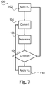
- Fig. 7 illustrates an exemplary method for operating a hearing aid comprising a microphone, a preprocessing unit, an A/D converter, and a processing unit according to the present invention.
- the method 100 comprises applying 102, in the preprocessing unit, a first transfer function H 1 to an audio signal from the microphone and converting 104 the preprocessed audio signal to a digital audio signal with the A/D converter. Further, the method comprises determining 106 one or more noise parameters including a first noise parameter and/or a second noise parameter of the digital audio signal, and applying 110, in the preprocessing unit, a second transfer function H 2 with a second cutoff frequency f 2 to the audio signal from the microphone depending on a noise criterion 108 based on the one or more noise parameters.
- the noise criterion applied in 108 depends on the mode of operation. If the preprocessing unit applies a first transfer function corresponding to the first mode of operation, a first criterion based on sound pressure levels is applied. If the first criterion is fulfilled, e.g. one or more sound pressure levels (total and/or selected bandwidths) are larger than respective thresholds, a control signal indicative of second mode is fed to the preprocessing unit and the preprocessing unit applies a second transfer function 110. If the first criterion is not fulfilled (indicative of no wind noise), the preprocessing unit continues applying the first transfer function corresponding to the hearing device operating in the first mode of operation.
- a first criterion based on sound pressure levels is applied. If the first criterion is fulfilled, e.g. one or more sound pressure levels (total and/or selected bandwidths) are larger than respective thresholds, a control signal indicative of second mode is fed to the preprocessing unit and the preprocessing unit applies a second transfer function 110. If the
- a second criterion is applied in 108.
- the second criterion may be fulfilled if the hearing device has operated in the second mode for a certain time period, i.e. if t 2 >T 1 , where t 2 is the present time of operation in the second mode and T 1 is a threshold time, e.g. in the range from 1 second to 60 seconds.
- t 2 is the present time of operation in the second mode
- T 1 is a threshold time, e.g. in the range from 1 second to 60 seconds.
- a control signal indicative of first mode is fed to the preprocessing unit and the preprocessing unit applies a first transfer function 102. If the second criterion is not fulfilled (indicative of wind noise present), the preprocessing unit continues applying the second transfer function and the hearing device continues operating in the second mode of operation.
- Fig. 8 illustrates an exemplary method for operating a hearing aid comprising a microphone, a preprocessing unit, an A/D converter, and a processing unit according to the present invention.
- the method 100' comprises applying 102, in the preprocessing unit, a first transfer function H 1 to an audio signal from the microphone and converting 104 the preprocessed audio signal to a digital audio signal with the A/D converter.
- the method comprises determining 106 one or more noise parameters including a first noise parameter and/or a second noise parameter of the digital audio signal. Further, an operation mode of the hearing device is determined based on the one or more noise parameters and the current mode of operation in 106. The operation mode may be selected from two or more operation modes with corresponding transfer functions. In 110, the transfer function corresponding to the mode of operation determined in 106 is applied to the audio signal and the method returns to determining the mode of operation and accordingly the transfer function to be applied in the preprocessing unit.
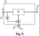
- Fig. 9 shows an exemplary processing unit 24.
- the processing unit 24 receives the digital audio signal 18 at input 93.
- the digital audio signal 18 is fed to detector unit 94 and hearing compensation processing unit 96.
- the detector unit 94 is configured to determine at least a first noise parameter of the digital audio signal 18.
- the noise parameter(s) are fed to mode selector 98 configured to determine the mode of operation of the hearing aid, e.g. based on the noise parameter(s) and/or current mode of operation.
- the mode selector 98 may be embedded in the hearing compensation processing unit 96.
- the mode selector 98 is configured to send a control signal 30 indicative of mode of operation to the preprocessing unit via processing unit control output 25.
Landscapes
- Health & Medical Sciences (AREA)
- General Health & Medical Sciences (AREA)
- Neurosurgery (AREA)
- Otolaryngology (AREA)
- Physics & Mathematics (AREA)
- Engineering & Computer Science (AREA)
- Acoustics & Sound (AREA)
- Signal Processing (AREA)
- Circuit For Audible Band Transducer (AREA)
Abstract
Description
- The present invention relates to a hearing device or hearing aid with analog filtering and associated method. In particular, the present invention relates to a hearing aid having improved wind noise reduction.
- Wind noise is experienced as very unpleasant by a hearing device user and considerably reduces the userfriendliness of a hearing device. Known methods for reducing wind noise in hearing devices include filtering in the digital domain. Further, it is known to reduce the gain of a preamplifier to remove the uncomfortable sound levels. This however is at the expence of normal sound processing basically getting destroyed rendering the hearing device somewhat unusable.
- Despite the known solutions, there is still a need for improving the hearing device processing during windy conditions and to improve the signal to noise ratio (SNR) in the hearing device.
- Accordingly, a hearing device is provided, the hearing device comprising: a microphone for converting audio into an audio signal; a preprocessing unit for analog processing of the audio signal and having an input and an output, wherein the input is connected to an output of the microphone; an A/D converter for converting the processed analog audio signal into a digital audio signal, the A/D converter having an input and an output, wherein the input is connected to the output of the preprocessing unit; and a processing unit for digital processing of A/D converter output, wherein the processing unit is connected to the preprocessing unit. The preprocessing unit is configured to apply a first transfer function to the audio signal in a first mode of operation and a second transfer function with a second cutoff frequency to the audio signal in a second mode of operation, depending on a control signal from the processing unit.
- Also disclosed is a method for operating a hearing aid comprising a microphone, a preprocessing unit, an A/D converter, and a processing unit is provided, the method comprising: applying, in the preprocessing unit, a first transfer function to an audio signal from the microphone; converting the preprocessed audio signal to a digital audio signal; determining one or more noise parameters including a first noise parameter: and applying, in the preprocessing unit, a second transfer function, e.g. with a second cutoff frequency, to the audio signal from the microphone depending on a noise criterion, e.g. a first noise criterion, based on the one or more noise parameters. The method may comprise determining the one or more noise parameters while applying the second transfer function, and applying, in the preprocessing unit, the first transfer function or a third transfer function to the audio signal from the microphone depending on a noise criterion, e.g. a second noise criterion.
- It is an advantage of the present invention that saturation of A/D converter of the hearing device is reduced thereby providing improved SNR in the hearing device processing.
- Further, the hearing device and method enable a more efficient use of signal processing ressources by removing undesired noise at an early stage in the signal processing of the hearing device. Thereby, improved power management is provided.
- The above and other features and advantages of the present invention will become readily apparent to those skilled in the art by the following detailed description of exemplary embodiments thereof with reference to the attached drawings, in which:
- Fig. 1
- schematically illustrates an exemplary hearing device,
- Fig. 2
- schematically illustrates an exemplary preprocessing circuit of the hearing device in
Fig. 1 , - Fig. 3
- schematically illustrates an exemplary preprocessing circuit of the hearing device in
Fig. 1 , - Fig. 4
- shows an exemplary resistance circuit with a variable resistance value,
- Fig. 5
- shows an exemplary capacitance circuit with a variable capacitance value,
- Fig. 6
- shows exemplary first and second transfer functions,
- Fig. 7
- is a flow diagram of an exemplary method,
- Fig. 8
- is a flow diagram of an exemplary method, and
- Fig. 9
- shows an exemplary processing unit.
- The figures are schematic and simplified for clarity, and they merely show details which are essential to the understanding of the invention, while other details have been left out. Throughout, the same reference numerals are used for identical or corresponding parts.
- The preprocessing unit processes the audio signal from the microphone and has an input and an output. The input comprises a first input terminal connected to an output, e.g. a first output terminal, of the microphone. The preprocessing unit may comprise one or more control terminals for receiving and/or sending control signal(s) from/to the processing unit.
- The preprocessing unit may comprise a first capacitor circuit with a first capacitance value. The first capacitance value may be variable, e.g. the first capacitance value may depend on the control signal from the processing unit. The preprocessing unit may comprise a second capacitor or second capacitor circuit having a second capacitance value. The second capacitance value may be variable, e.g. the second capacitance value may depend on the control signal from the processing unit. A variable first and/or second capacitance circuit may reduce the microphone requirements with regard to DC biasing or drifting. A capacitor or capacitor circuit has a first and a second terminal having a capacitance value therebetween.
- The preprocessing unit may comprise a first resistor circuit with a first resistance value. The first resistance value may be variable, e.g. the first resistance value may depend on the control signal from the processing unit. The preprocessing unit may comprise a second resistor circuit with a second resistance value. The second resistance value may be variable, e.g. the second resistance value may depend on the control signal from the processing unit. A resistor or resistor circuit has a first and a second terminal having a resistance value therebetween.
- The preprocessing unit may be a passive unit or an active unit. Accordingly, the preprocessing unit may comprise an amplifier. The amplifier has a first and optionally a second input terminal and an output terminal. The preprocessing unit may comprise a first part or unit and a second part or unit, where the first part is a passive filter part with adjustable filter parameters via the control signal and the second part is an active part with an amplifier. Accordingly, the preprocessing unit may comprise a passive adjustable filter unit followed by an active amplifier unit with adjustable gain.
- The processing unit comprises an input with one or more input terminals including a first input terminal. The processing unit comprises one or more control terminals connected to corresponding control terminals of the preprocessing unit for sending and/or receiving control signal(s) indicative of mode of operation to/from the preprocessing unit.
- The processing unit is configured to send a control signal to the preprocessing unit indicative of a mode of operation. The control signal may comprise one or more bits, e.g. depending on the number number of modes/transfer functions. The control signal may have a first value indicative of the first transfer function (e.g. Bit1=0) and a second value indicative of a second transfer function (e.g. Bit1=1). The processing unit may comprise a detector unit configured to determine one or more noise parameters including a first noise parameter and/or a second noise parameter. The noise parameter(s) may be indicative of the amount of wind noise in the audio signal. The processing unit may be configured to send a control signal indicative of mode of operation to the preprocessing unit depending on a noise criterion based on one or more of the noise parameters. The detector unit may be configured to determine a saturation parameter indicative of whether the A/D converter is close to or in saturation. The processing unit may be configured to send a control signal indicative of mode of operation to the preprocessing unit based on the saturation parameter.
- A noise criterion may be applied for determining the mode of operation. For example, a first mode (first transfer function) may be selected when a noise criterion, e.g. a first noise criterion, based on noise parameter(s) is not fulfilled, e.g. if a first noise parameter is less than, equal to or larger than a noise threshold (e.g. a first noise threshold). Further, a second mode (second transfer function) may be selected when a noise criterion, e.g. the first noise criterion or a second noise criterion, based on the noise parameter(s) is fulfilled, e.g. if the first noise parameter is less than, equal to or larger than a noise threshold (e.g. the first noise threshold or a second noise threshold). Different criteria may be applied depending on the mode of operation.
- In an exemplary hearing device, a noise parameter may be based on the sound pressure level (SPL) of the digital audio signal and/or the sound pressure level (SPL) in one or more frequency bands of the digital audio signal, e.g. a first frequency band F1 and/or a second frequency band F2. It is contemplated that a noise criterion and/or the noise parameter may be based on SPL or other suitable input signal properties determined by the detector unit or other sound classification units in the hearing device.
- In an exemplary hearing device, a noise criterion in the first mode of operation is given by

- In an exemplary hearing device, the noise criterion in the first mode of operation is given by

- The noise criterion may be based on a plurality of noise parameters. In an exemplary hearing device, the noise criterion in the first mode of operation is given by

- A first noise criterion may be applied in a first mode of operation and a second noise criterion different from the first noise criterion may be applied in a second mode of operation. The hearing device may be configured to operate in the second mode for a predetermined time period and then switch back to the first mode. For example, the second noise criterion may consist of or include whether the hearing device has operated in the second mode for a certain period of time. A noise criterion may comprise one or more logical expressions.
- The preprocessing unit may be configured to apply a third transfer function with a third cutoff frequency to the audio signal in a third mode of operation depending on the control signal from the processing unit.
- The preprocessing unit is configured to apply a plurality of different transfer functions including a first transfer function and a second transfer function to the output signal from the microphone in different modes of operation, e.g. depending on control signal(s) from the processing unit.
- The first transfer function may be a high pass filter function having a first cutoff frequency f1. The first cutoff frequency may be selected in the range from 5 Hz to 1 kHz. Exemplary first cutoff frequencies are 20 Hz, 50 Hz, 80 Hz, 100 Hz, 200 Hz, 400 Hz, 600 Hz, 1 kHz or any ranges therebetween.
- The second transfer function may be a high pass filter function. The second cutoff frequency f2 may be selected in the range from 50 Hz to 2 kHz. Exemplary second cutoff frequencies are 50 Hz, 80 Hz, 100 Hz, 200 Hz, 400 Hz, 600 Hz, 800 Hz, 1 kHz, 2 kHz or any ranges therebetween. The first cutoff frequency may be less than the second cutoff frequency, e.g. f1=80Hz and f2=400 Hz .
- The transfer functions applied in different modes may be band-pass filter functions with lower cutoff corresponding to the first and second cutoff frequencies, respectively.
- The processing unit may be configured to send a control signal indicative of a second mode of operation to the preprocessing unit when a first noise criterion is fulfilled in a first mode of operation where a first transfer function is applied. Additionally or as an alternative, the processing unit may be configured to send a control signal indicative of a first mode of operation to the preprocessing unit when a second noise criterion is fulfilled in a second mode of operation where a second transfer function is applied.
- The method according to the present invention comprises applying, in the preprocessing unit, a second transfer function with a second cutoff frequency to the audio signal from the microphone if the noise parameter fullfils a criterion. The method may comprise determining the noise parameter(s) while applying the second transfer function, and applying, in the preprocessing unit, the first transfer function or a third transfer function to the audio signal from the microphone if the noise parameter(s) fullfils a criterion. A first criterion may be applied when the first transfer function is applied in the preprocessing unit and a second criterion different from the first criterion may be applied when the second transfer function is applied in the preprocessing unit.
- The hearing device according to the present invention provides improved degree of freedom in the design of the hearing device by reducing the requirements to microphone performance.
- Further, the present invention allows for utilizing low frequency audio signals for secondary applications not necessarily related to hearing loss compensation.
-
Fig. 1 schematically illustrates an exemplary hearing device. Thehearing device 2 comprises amicrophone 4 for converting audio into anaudio signal 5, and apreprocessing unit 6 for analog processing of theaudio signal 5. The preprocessing unit has an input 8 foraudio signal 5 and anoutput 10, wherein the input 8 is connected to anoutput 12 of themicrophone 4. Further, thehearing device 2 comprises an A/D converter 14 for converting the processedanalog audio signal 16 into adigital audio signal 18, the A/D converter 14 having aninput 20 and anoutput 22, wherein theinput 20 is connected to theoutput 10 of thepreprocessing unit 6. The hearing device comprises aprocessing unit 24 for digital processing of thedigital audio signal 18. The processeddigital audio signal 26 is fed to a receiver device (not shown) for conversion of the processeddigital audio signal 26 into a compensated audio signal. Theprocessing unit 24 is connected to thepreprocessing unit 6 onconnection 28 for feeding and/or receiving control signal(s) to/from the preprocessing unit. - The
preprocessing unit 6 is configured to apply a first transfer function H1 to the audio signal in a first mode of operation and a second transfer function H2 with a second cutoff frequency to the audio signal in a second mode of operation, depending on acontrol signal 30 onconnection 28 from theprocessing unit 24. -
Fig. 2 shows an exemplary preprocessing unit 6' of thehearing aid 2. The preprocessing unit 6' comprises afirst capacitance circuit 40 with a variable first capacitance value C1 depending on a control signal on control terminal(s) 42. Further, the preprocessing unit 6' comprises a second capacitance circuit 44 with a second capacitance value C2. The preprocessing unit 6' comprises afirst resistance circuit 46 with a variable first resistance value R1 depending on a control signal on control terminal(s) 42'. The preprocessing unit 6' is an active unit comprising an amplifier oramplifier circuit 48 having afirst input terminal 49A, asecond input terminal 49B, andoutput terminal 50 coupled to the capacitance andresistance circuits first capacitance circuit 40 is coupled between afirst input terminal 47 of the preprocessing unit input 8 and thefirst input terminal 49A. The second capacitance circuit 44 and thefirst resistance circuit 46 are coupled in parallel between thefirst input terminal 49A and theoutput terminal 50. Thesecond input terminal 49B is connected to virtual ground. -
Fig. 3 shows anexemplary preprocessing unit 6" of thehearing aid 2. Thepreprocessing unit 6" comprises afirst resistance circuit 46 with a variable first resistance value R1 depending on a control signal on control terminal(s) 42'. Further, thepreprocessing unit 6" comprises a second resistance circuit 52 with a variable second resistance value R2 depending on a control signal on control terminal(s) 42". Thepreprocessing unit 6" is an active unit comprising an amplifier oramplifier circuit 48 having afirst input terminal 49A, asecond input terminal 49B, andoutput terminal 50. Thefirst resistance circuit 46 is coupled between thesecond input terminal 49B and theoutput terminal 50. The second resistance circuit 52 is coupled between thesecond input terminal 49B and thesecond input terminal 47" of the preprocessing unit. A capacitance circuit (not shown) is coupled external to the preprocessing unit between the second input terminal 47' and ground. As an alternative or in combination, a first capacitance circuit (C1) may be incorporated in thepreprocessing unit 6" in series with the second resistance circuit 52 between ground and thesecond input terminal 49B. -
Fig. 4 shows an exemplary resistance circuit with a variable resistance value. Different resistance values may be selected by controlling the switches 56 (open or closed) with a control signal in order to couple or decoupleresistors 54. -
Fig. 5 shows an exemplary capacitance circuit with a variable capacitance value. Different capacitance values may be selected by controlling the switches 56 (open or closed) with a control signal in order to couple or decouplecapacitors 58. -
Fig. 6 shows exemplary first and second transfer functions applied to the audio signal in first and second modes of operation, respectively. Thefirst transfer function 90 is a high pass filter with a first cutoff frequency f1 of about 100 Hz. Thesecond transfer function 92 is a high pass filter with a second cutoff frequency f2 of about 400 Hz. -
Fig. 7 illustrates an exemplary method for operating a hearing aid comprising a microphone, a preprocessing unit, an A/D converter, and a processing unit according to the present invention. Themethod 100 comprises applying 102, in the preprocessing unit, a first transfer function H1 to an audio signal from the microphone and converting 104 the preprocessed audio signal to a digital audio signal with the A/D converter. Further, the method comprises determining 106 one or more noise parameters including a first noise parameter and/or a second noise parameter of the digital audio signal, and applying 110, in the preprocessing unit, a second transfer function H2 with a second cutoff frequency f2 to the audio signal from the microphone depending on anoise criterion 108 based on the one or more noise parameters. In themethod 100, the noise criterion applied in 108 depends on the mode of operation. If the preprocessing unit applies a first transfer function corresponding to the first mode of operation, a first criterion based on sound pressure levels is applied. If the first criterion is fulfilled, e.g. one or more sound pressure levels (total and/or selected bandwidths) are larger than respective thresholds, a control signal indicative of second mode is fed to the preprocessing unit and the preprocessing unit applies asecond transfer function 110. If the first criterion is not fulfilled (indicative of no wind noise), the preprocessing unit continues applying the first transfer function corresponding to the hearing device operating in the first mode of operation. If the preprocessing unit applies a second transfer function corresponding to the second mode of operation, a second criterion is applied in 108. The second criterion may be fulfilled if the hearing device has operated in the second mode for a certain time period, i.e. if t2>T1, where t2 is the present time of operation in the second mode and T1 is a threshold time, e.g. in the range from 1 second to 60 seconds. If the second criterion is fulfilled, a control signal indicative of first mode is fed to the preprocessing unit and the preprocessing unit applies afirst transfer function 102. If the second criterion is not fulfilled (indicative of wind noise present), the preprocessing unit continues applying the second transfer function and the hearing device continues operating in the second mode of operation. -
Fig. 8 illustrates an exemplary method for operating a hearing aid comprising a microphone, a preprocessing unit, an A/D converter, and a processing unit according to the present invention. The method 100' comprises applying 102, in the preprocessing unit, a first transfer function H1 to an audio signal from the microphone and converting 104 the preprocessed audio signal to a digital audio signal with the A/D converter. - Further, the method comprises determining 106 one or more noise parameters including a first noise parameter and/or a second noise parameter of the digital audio signal. Further, an operation mode of the hearing device is determined based on the one or more noise parameters and the current mode of operation in 106. The operation mode may be selected from two or more operation modes with corresponding transfer functions. In 110, the transfer function corresponding to the mode of operation determined in 106 is applied to the audio signal and the method returns to determining the mode of operation and accordingly the transfer function to be applied in the preprocessing unit.
-
Fig. 9 shows anexemplary processing unit 24. Theprocessing unit 24 receives thedigital audio signal 18 atinput 93. Thedigital audio signal 18 is fed todetector unit 94 and hearingcompensation processing unit 96. Thedetector unit 94 is configured to determine at least a first noise parameter of thedigital audio signal 18. The noise parameter(s) are fed tomode selector 98 configured to determine the mode of operation of the hearing aid, e.g. based on the noise parameter(s) and/or current mode of operation. Themode selector 98 may be embedded in the hearingcompensation processing unit 96. Themode selector 98 is configured to send acontrol signal 30 indicative of mode of operation to the preprocessing unit via processingunit control output 25. -
- 2
- hearing device
- 4
- microphone
- 5
- audio signal
- 6
- preprocessing unit
- 8
- preprocessing unit input
- 10
- preprocessing unit output
- 12
- microphone output
- 14
- analog-digital (A/D) converter
- 16
- processed analog audio signal
- 18
- digital audio signal
- 20
- A/D converter input
- 22
- A/D converter output
- 24
- processing unit
- 25
- processing unit control output
- 26
- processed digital audio signal
- 28
- connection
- 30
- control signal
- 40
- first capacitance circuit
- 42, 42', 42"
- control terminal(s)
- 44
- second capacitance circuit
- 46
- first resistance circuit
- 47
- first input terminal
- 48
- amplifier
- 49A
- first input terminal of amplifier
- 49B
- second input terminal of amplifier
- 50
- output terminal of amplifier
- 52
- second resistance circuit
- 54
- resistor
- 56
- switch
- 58
- capacitor
- 90
- first transfer function
- 92
- second transfer function
- 93
- digital audio input
- 94
- detector unit
- 96
- hearing compensation processing unit
- 98
- mode selector
Claims (13)
- A hearing device comprising:- a microphone for converting audio into an audio signal;- a preprocessing unit for analog processing of the audio signal and having an input and an output, wherein the input is connected to an output of the microphone;- an A/D converter for converting the processed analog audio signal into a digital audio signal, the A/D converter having an input and an output, wherein the input is connected to the output of the preprocessing unit; and- a processing unit for digital processing of A/D converter output, wherein the processing unit is connected to the preprocessing unit;wherein the preprocessing unit is configured to apply a first transfer function to the audio signal in a first mode of operation and a second transfer function with a second cutoff frequency to the audio signal in a second mode of operation, depending on a control signal from the processing unit.
- A hearing device according to claim 1, wherein the preprocessing unit comprises a first capacitor circuit with a variable first capacitance value, wherein the first capacitance value depends on the control signal from the processing unit.
- A hearing device according to any of claims 1-2, wherein the preprocessing unit comprises a first resistor circuit with a variable first resistance value, wherein the second resistance value depends on the control signal from the processing unit.
- A hearing device according to claim 3, wherein the preprocessing unit comprises a second resistor circuit with a variable second resistance value, wherein the second resistance value depends on the control signal from the processing unit.
- A hearing device according to any of the preceding claims, wherein the preprocessing unit comprises an amplifier.
- A hearing device according to any of the preceding claims, wherein the processing unit comprises a detector unit configured to determine one or more noise parameters including a first noise parameter, and wherein the processing unit is configured to send a control signal indicative of mode of operation to the preprocessing unit depending on a noise criterion based on the one or more noise parameter(s).
- A hearing device according to any of the preceding claims, wherein the processing unit is configured to send a control signal indicative of a second mode of operation to the preprocessing unit when a first noise criterion is fulfilled in a first mode of operation, and a control signal indicative of a first mode of operation to the preprocessing unit when a second noise criterion is fulfilled in a second mode of operation.
- A hearing device according to any of the preceding claims, wherein the preprocessing unit is configured to apply a third transfer function with a third cutoff frequency to the audio signal in a third mode of operation depending on the control signal from the processing unit.
- A hearing device according to any of the preceding claims, wherein the first transfer function is a high pass filter function and having a first cutoff frequency, wherein the first cutoff frequency is selected in the range from 100 Hz to 1 kHz.
- A hearing device according to claim 9, wherein the second cutoff frequency is larger than the first cutoff frequency.
- A hearing device according to any of the preceding claims, wherein the second transfer function is a high pass filter function and wherein the second cutoff frequency is selected in the range from 100 Hz to 2 kHz.
- A method for operating a hearing aid comprising a microphone, a preprocessing unit, an A/D converter, and a processing unit, the method comprising:- applying, in the preprocessing unit, a first transfer function to an audio signal from the microphone,- converting the preprocessed audio signal to a digital audio signal,- determining one or more noise parameters including a first noise parameter, and- applying, in the preprocessing unit, a second transfer function with a second cutoff frequency to the audio signal from the microphone depending on a noise criterion based on the one or more noise parameters.
- Method according to claim 12, the method comprising determining the one or more noise parameters while applying the second transfer function, and applying, in the preprocessing unit, the first transfer function or a third transfer function to the audio signal from the microphone depending on a noise criterion.
Priority Applications (2)
| Application Number | Priority Date | Filing Date | Title |
|---|---|---|---|
| EP18156397.4A EP3340658B1 (en) | 2012-11-30 | 2012-11-30 | Hearing device with analog filtering and associated method |
| DK18156397.4T DK3340658T3 (en) | 2012-11-30 | 2012-11-30 | Hearing aid with analog filtering and associated procedure |
Applications Claiming Priority (2)
| Application Number | Priority Date | Filing Date | Title |
|---|---|---|---|
| EP12195007.5A EP2739069B1 (en) | 2012-11-30 | 2012-11-30 | Hearing device with analog filtering and associated method |
| EP18156397.4A EP3340658B1 (en) | 2012-11-30 | 2012-11-30 | Hearing device with analog filtering and associated method |
Related Parent Applications (1)
| Application Number | Title | Priority Date | Filing Date |
|---|---|---|---|
| EP12195007.5A Division EP2739069B1 (en) | 2012-11-30 | 2012-11-30 | Hearing device with analog filtering and associated method |
Publications (2)
| Publication Number | Publication Date |
|---|---|
| EP3340658A1 true EP3340658A1 (en) | 2018-06-27 |
| EP3340658B1 EP3340658B1 (en) | 2020-12-23 |
Family
ID=47325900
Family Applications (2)
| Application Number | Title | Priority Date | Filing Date |
|---|---|---|---|
| EP12195007.5A Active EP2739069B1 (en) | 2012-11-30 | 2012-11-30 | Hearing device with analog filtering and associated method |
| EP18156397.4A Active EP3340658B1 (en) | 2012-11-30 | 2012-11-30 | Hearing device with analog filtering and associated method |
Family Applications Before (1)
| Application Number | Title | Priority Date | Filing Date |
|---|---|---|---|
| EP12195007.5A Active EP2739069B1 (en) | 2012-11-30 | 2012-11-30 | Hearing device with analog filtering and associated method |
Country Status (2)
| Country | Link |
|---|---|
| EP (2) | EP2739069B1 (en) |
| DK (2) | DK2739069T3 (en) |
Families Citing this family (1)
| Publication number | Priority date | Publication date | Assignee | Title |
|---|---|---|---|---|
| CN120108410B (en) * | 2023-12-04 | 2026-03-31 | 北京嘀嘀无限科技发展有限公司 | Methods for processing audio signals, electronic devices, and vehicles |
Citations (5)
| Publication number | Priority date | Publication date | Assignee | Title |
|---|---|---|---|---|
| US5170434A (en) * | 1988-08-30 | 1992-12-08 | Beltone Electronics Corporation | Hearing aid with improved noise discrimination |
| EP1258865A2 (en) * | 2001-05-18 | 2002-11-20 | Micronas GmbH | Device for improving the intelligibility of audio signals containing speech |
| US20040175012A1 (en) * | 2003-03-03 | 2004-09-09 | Hans-Ueli Roeck | Method for manufacturing acoustical devices and for reducing especially wind disturbances |
| WO2011006496A1 (en) * | 2009-07-15 | 2011-01-20 | Widex A/S | Method and processing unit for adaptive wind noise suppression in a hearing aid system and a hearing aid system |
| US20120207315A1 (en) * | 2011-02-10 | 2012-08-16 | Canon Kabushiki Kaisha | Audio processing apparatus and method of controlling the audio processing apparatus |
-
2012
- 2012-11-30 DK DK12195007.5T patent/DK2739069T3/en active
- 2012-11-30 EP EP12195007.5A patent/EP2739069B1/en active Active
- 2012-11-30 EP EP18156397.4A patent/EP3340658B1/en active Active
- 2012-11-30 DK DK18156397.4T patent/DK3340658T3/en active
Patent Citations (5)
| Publication number | Priority date | Publication date | Assignee | Title |
|---|---|---|---|---|
| US5170434A (en) * | 1988-08-30 | 1992-12-08 | Beltone Electronics Corporation | Hearing aid with improved noise discrimination |
| EP1258865A2 (en) * | 2001-05-18 | 2002-11-20 | Micronas GmbH | Device for improving the intelligibility of audio signals containing speech |
| US20040175012A1 (en) * | 2003-03-03 | 2004-09-09 | Hans-Ueli Roeck | Method for manufacturing acoustical devices and for reducing especially wind disturbances |
| WO2011006496A1 (en) * | 2009-07-15 | 2011-01-20 | Widex A/S | Method and processing unit for adaptive wind noise suppression in a hearing aid system and a hearing aid system |
| US20120207315A1 (en) * | 2011-02-10 | 2012-08-16 | Canon Kabushiki Kaisha | Audio processing apparatus and method of controlling the audio processing apparatus |
Also Published As
| Publication number | Publication date |
|---|---|
| EP3340658B1 (en) | 2020-12-23 |
| EP2739069B1 (en) | 2018-02-14 |
| EP2739069A1 (en) | 2014-06-04 |
| DK2739069T3 (en) | 2018-03-05 |
| DK3340658T3 (en) | 2021-02-22 |
Similar Documents
| Publication | Publication Date | Title |
|---|---|---|
| US9407998B2 (en) | Hearing device with analog filtering and associated method | |
| US6198830B1 (en) | Method and circuit for the amplification of input signals of a hearing aid | |
| DE69531828T2 (en) | HEARING AID WITH SIGNAL PROCESSING TECHNIQUES | |
| US4953216A (en) | Apparatus for the transmission of speech | |
| US7068802B2 (en) | Method for the operation of a digital, programmable hearing aid as well as a digitally programmable hearing aid | |
| DE102007046437B4 (en) | Fully automatic switching on / off for hearing aids | |
| US6404895B1 (en) | Method for feedback recognition in a hearing aid and a hearing aid operating according to the method | |
| US10429421B2 (en) | Method of operating a hearing aid system and a hearing aid system | |
| US9832562B2 (en) | Hearing aid with probabilistic hearing loss compensation | |
| EP1448022A1 (en) | Dynamic Compression in a hearing aid | |
| US20100262424A1 (en) | Method of Eliminating Background Noise and a Device Using the Same | |
| CN110072175B (en) | Control circuit and method for reducing wind noise | |
| US8045738B2 (en) | System for managing feedback | |
| JP2003511880A (en) | Method and signal processing device for enhancing speech signal components in hearing aids | |
| JPH10242780A (en) | Method for automatically limiting distortion in audio equipment and circuit arrangement for implementing the method | |
| EP1926343B1 (en) | Hearing aid with automatic deactivation and a corresponding method | |
| CN111341337B (en) | Sound noise reduction algorithm and system thereof | |
| US8587376B2 (en) | Automatic gain control | |
| EP2739069A1 (en) | Hearing device with analog filtering and associated method | |
| US7024011B1 (en) | Hearing aid with an oscillation detector, and method for detecting feedback in a hearing aid | |
| EP3379847B1 (en) | Audio device, speaker device, and audio signal processing method | |
| CN107181998A (en) | Sound volume control system and method | |
| JP2012063394A (en) | Noise suppression device, noise suppression method, and program | |
| GB2609303A (en) | Single-microphone wind detector for audio device | |
| EP3048813B1 (en) | Method and device for suppressing noise based on inter-subband correlation |
Legal Events
| Date | Code | Title | Description |
|---|---|---|---|
| PUAI | Public reference made under article 153(3) epc to a published international application that has entered the european phase |
Free format text: ORIGINAL CODE: 0009012 |
|
| STAA | Information on the status of an ep patent application or granted ep patent |
Free format text: STATUS: THE APPLICATION HAS BEEN PUBLISHED |
|
| AC | Divisional application: reference to earlier application |
Ref document number: 2739069 Country of ref document: EP Kind code of ref document: P |
|
| AK | Designated contracting states |
Kind code of ref document: A1 Designated state(s): AL AT BE BG CH CY CZ DE DK EE ES FI FR GB GR HR HU IE IS IT LI LT LU LV MC MK MT NL NO PL PT RO RS SE SI SK SM TR |
|
| STAA | Information on the status of an ep patent application or granted ep patent |
Free format text: STATUS: REQUEST FOR EXAMINATION WAS MADE |
|
| 17P | Request for examination filed |
Effective date: 20181219 |
|
| RBV | Designated contracting states (corrected) |
Designated state(s): AL AT BE BG CH CY CZ DE DK EE ES FI FR GB GR HR HU IE IS IT LI LT LU LV MC MK MT NL NO PL PT RO RS SE SI SK SM TR |
|
| STAA | Information on the status of an ep patent application or granted ep patent |
Free format text: STATUS: EXAMINATION IS IN PROGRESS |
|
| 17Q | First examination report despatched |
Effective date: 20190730 |
|
| GRAP | Despatch of communication of intention to grant a patent |
Free format text: ORIGINAL CODE: EPIDOSNIGR1 |
|
| STAA | Information on the status of an ep patent application or granted ep patent |
Free format text: STATUS: GRANT OF PATENT IS INTENDED |
|
| INTG | Intention to grant announced |
Effective date: 20200228 |
|
| GRAJ | Information related to disapproval of communication of intention to grant by the applicant or resumption of examination proceedings by the epo deleted |
Free format text: ORIGINAL CODE: EPIDOSDIGR1 |
|
| STAA | Information on the status of an ep patent application or granted ep patent |
Free format text: STATUS: EXAMINATION IS IN PROGRESS |
|
| GRAP | Despatch of communication of intention to grant a patent |
Free format text: ORIGINAL CODE: EPIDOSNIGR1 |
|
| STAA | Information on the status of an ep patent application or granted ep patent |
Free format text: STATUS: GRANT OF PATENT IS INTENDED |
|
| INTC | Intention to grant announced (deleted) | ||
| INTG | Intention to grant announced |
Effective date: 20200721 |
|
| GRAS | Grant fee paid |
Free format text: ORIGINAL CODE: EPIDOSNIGR3 |
|
| GRAA | (expected) grant |
Free format text: ORIGINAL CODE: 0009210 |
|
| STAA | Information on the status of an ep patent application or granted ep patent |
Free format text: STATUS: THE PATENT HAS BEEN GRANTED |
|
| AC | Divisional application: reference to earlier application |
Ref document number: 2739069 Country of ref document: EP Kind code of ref document: P |
|
| AK | Designated contracting states |
Kind code of ref document: B1 Designated state(s): AL AT BE BG CH CY CZ DE DK EE ES FI FR GB GR HR HU IE IS IT LI LT LU LV MC MK MT NL NO PL PT RO RS SE SI SK SM TR |
|
| REG | Reference to a national code |
Ref country code: GB Ref legal event code: FG4D |
|
| REG | Reference to a national code |
Ref country code: DE Ref legal event code: R096 Ref document number: 602012073897 Country of ref document: DE |
|
| REG | Reference to a national code |
Ref country code: AT Ref legal event code: REF Ref document number: 1348880 Country of ref document: AT Kind code of ref document: T Effective date: 20210115 |
|
| REG | Reference to a national code |
Ref country code: IE Ref legal event code: FG4D |
|
| REG | Reference to a national code |
Ref country code: DK Ref legal event code: T3 Effective date: 20210219 |
|
| PG25 | Lapsed in a contracting state [announced via postgrant information from national office to epo] |
Ref country code: GR Free format text: LAPSE BECAUSE OF FAILURE TO SUBMIT A TRANSLATION OF THE DESCRIPTION OR TO PAY THE FEE WITHIN THE PRESCRIBED TIME-LIMIT Effective date: 20210324 Ref country code: NO Free format text: LAPSE BECAUSE OF FAILURE TO SUBMIT A TRANSLATION OF THE DESCRIPTION OR TO PAY THE FEE WITHIN THE PRESCRIBED TIME-LIMIT Effective date: 20210323 Ref country code: FI Free format text: LAPSE BECAUSE OF FAILURE TO SUBMIT A TRANSLATION OF THE DESCRIPTION OR TO PAY THE FEE WITHIN THE PRESCRIBED TIME-LIMIT Effective date: 20201223 Ref country code: RS Free format text: LAPSE BECAUSE OF FAILURE TO SUBMIT A TRANSLATION OF THE DESCRIPTION OR TO PAY THE FEE WITHIN THE PRESCRIBED TIME-LIMIT Effective date: 20201223 |
|
| REG | Reference to a national code |
Ref country code: AT Ref legal event code: MK05 Ref document number: 1348880 Country of ref document: AT Kind code of ref document: T Effective date: 20201223 |
|
| REG | Reference to a national code |
Ref country code: NL Ref legal event code: MP Effective date: 20201223 |
|
| PG25 | Lapsed in a contracting state [announced via postgrant information from national office to epo] |
Ref country code: SE Free format text: LAPSE BECAUSE OF FAILURE TO SUBMIT A TRANSLATION OF THE DESCRIPTION OR TO PAY THE FEE WITHIN THE PRESCRIBED TIME-LIMIT Effective date: 20201223 Ref country code: LV Free format text: LAPSE BECAUSE OF FAILURE TO SUBMIT A TRANSLATION OF THE DESCRIPTION OR TO PAY THE FEE WITHIN THE PRESCRIBED TIME-LIMIT Effective date: 20201223 Ref country code: BG Free format text: LAPSE BECAUSE OF FAILURE TO SUBMIT A TRANSLATION OF THE DESCRIPTION OR TO PAY THE FEE WITHIN THE PRESCRIBED TIME-LIMIT Effective date: 20210323 |
|
| PG25 | Lapsed in a contracting state [announced via postgrant information from national office to epo] |
Ref country code: NL Free format text: LAPSE BECAUSE OF FAILURE TO SUBMIT A TRANSLATION OF THE DESCRIPTION OR TO PAY THE FEE WITHIN THE PRESCRIBED TIME-LIMIT Effective date: 20201223 Ref country code: HR Free format text: LAPSE BECAUSE OF FAILURE TO SUBMIT A TRANSLATION OF THE DESCRIPTION OR TO PAY THE FEE WITHIN THE PRESCRIBED TIME-LIMIT Effective date: 20201223 |
|
| REG | Reference to a national code |
Ref country code: LT Ref legal event code: MG9D |
|
| PG25 | Lapsed in a contracting state [announced via postgrant information from national office to epo] |
Ref country code: PT Free format text: LAPSE BECAUSE OF FAILURE TO SUBMIT A TRANSLATION OF THE DESCRIPTION OR TO PAY THE FEE WITHIN THE PRESCRIBED TIME-LIMIT Effective date: 20210423 Ref country code: SK Free format text: LAPSE BECAUSE OF FAILURE TO SUBMIT A TRANSLATION OF THE DESCRIPTION OR TO PAY THE FEE WITHIN THE PRESCRIBED TIME-LIMIT Effective date: 20201223 Ref country code: RO Free format text: LAPSE BECAUSE OF FAILURE TO SUBMIT A TRANSLATION OF THE DESCRIPTION OR TO PAY THE FEE WITHIN THE PRESCRIBED TIME-LIMIT Effective date: 20201223 Ref country code: CZ Free format text: LAPSE BECAUSE OF FAILURE TO SUBMIT A TRANSLATION OF THE DESCRIPTION OR TO PAY THE FEE WITHIN THE PRESCRIBED TIME-LIMIT Effective date: 20201223 Ref country code: EE Free format text: LAPSE BECAUSE OF FAILURE TO SUBMIT A TRANSLATION OF THE DESCRIPTION OR TO PAY THE FEE WITHIN THE PRESCRIBED TIME-LIMIT Effective date: 20201223 Ref country code: LT Free format text: LAPSE BECAUSE OF FAILURE TO SUBMIT A TRANSLATION OF THE DESCRIPTION OR TO PAY THE FEE WITHIN THE PRESCRIBED TIME-LIMIT Effective date: 20201223 Ref country code: SM Free format text: LAPSE BECAUSE OF FAILURE TO SUBMIT A TRANSLATION OF THE DESCRIPTION OR TO PAY THE FEE WITHIN THE PRESCRIBED TIME-LIMIT Effective date: 20201223 |
|
| PG25 | Lapsed in a contracting state [announced via postgrant information from national office to epo] |
Ref country code: AT Free format text: LAPSE BECAUSE OF FAILURE TO SUBMIT A TRANSLATION OF THE DESCRIPTION OR TO PAY THE FEE WITHIN THE PRESCRIBED TIME-LIMIT Effective date: 20201223 Ref country code: PL Free format text: LAPSE BECAUSE OF FAILURE TO SUBMIT A TRANSLATION OF THE DESCRIPTION OR TO PAY THE FEE WITHIN THE PRESCRIBED TIME-LIMIT Effective date: 20201223 |
|
| REG | Reference to a national code |
Ref country code: DE Ref legal event code: R097 Ref document number: 602012073897 Country of ref document: DE |
|
| PG25 | Lapsed in a contracting state [announced via postgrant information from national office to epo] |
Ref country code: IS Free format text: LAPSE BECAUSE OF FAILURE TO SUBMIT A TRANSLATION OF THE DESCRIPTION OR TO PAY THE FEE WITHIN THE PRESCRIBED TIME-LIMIT Effective date: 20210423 |
|
| PG25 | Lapsed in a contracting state [announced via postgrant information from national office to epo] |
Ref country code: AL Free format text: LAPSE BECAUSE OF FAILURE TO SUBMIT A TRANSLATION OF THE DESCRIPTION OR TO PAY THE FEE WITHIN THE PRESCRIBED TIME-LIMIT Effective date: 20201223 Ref country code: IT Free format text: LAPSE BECAUSE OF FAILURE TO SUBMIT A TRANSLATION OF THE DESCRIPTION OR TO PAY THE FEE WITHIN THE PRESCRIBED TIME-LIMIT Effective date: 20201223 |
|
| PLBE | No opposition filed within time limit |
Free format text: ORIGINAL CODE: 0009261 |
|
| STAA | Information on the status of an ep patent application or granted ep patent |
Free format text: STATUS: NO OPPOSITION FILED WITHIN TIME LIMIT |
|
| 26N | No opposition filed |
Effective date: 20210924 |
|
| PG25 | Lapsed in a contracting state [announced via postgrant information from national office to epo] |
Ref country code: ES Free format text: LAPSE BECAUSE OF FAILURE TO SUBMIT A TRANSLATION OF THE DESCRIPTION OR TO PAY THE FEE WITHIN THE PRESCRIBED TIME-LIMIT Effective date: 20201223 |
|
| PG25 | Lapsed in a contracting state [announced via postgrant information from national office to epo] |
Ref country code: SI Free format text: LAPSE BECAUSE OF FAILURE TO SUBMIT A TRANSLATION OF THE DESCRIPTION OR TO PAY THE FEE WITHIN THE PRESCRIBED TIME-LIMIT Effective date: 20201223 |
|
| PG25 | Lapsed in a contracting state [announced via postgrant information from national office to epo] |
Ref country code: MC Free format text: LAPSE BECAUSE OF FAILURE TO SUBMIT A TRANSLATION OF THE DESCRIPTION OR TO PAY THE FEE WITHIN THE PRESCRIBED TIME-LIMIT Effective date: 20201223 |
|
| PG25 | Lapsed in a contracting state [announced via postgrant information from national office to epo] |
Ref country code: LU Free format text: LAPSE BECAUSE OF NON-PAYMENT OF DUE FEES Effective date: 20211130 Ref country code: BE Free format text: LAPSE BECAUSE OF NON-PAYMENT OF DUE FEES Effective date: 20211130 |
|
| REG | Reference to a national code |
Ref country code: BE Ref legal event code: MM Effective date: 20211130 |
|
| PG25 | Lapsed in a contracting state [announced via postgrant information from national office to epo] |
Ref country code: IE Free format text: LAPSE BECAUSE OF NON-PAYMENT OF DUE FEES Effective date: 20211130 |
|
| PGFP | Annual fee paid to national office [announced via postgrant information from national office to epo] |
Ref country code: GB Payment date: 20221117 Year of fee payment: 11 Ref country code: FR Payment date: 20221115 Year of fee payment: 11 Ref country code: DK Payment date: 20221115 Year of fee payment: 11 Ref country code: DE Payment date: 20221117 Year of fee payment: 11 |
|
| PGFP | Annual fee paid to national office [announced via postgrant information from national office to epo] |
Ref country code: CH Payment date: 20221121 Year of fee payment: 11 |
|
| PG25 | Lapsed in a contracting state [announced via postgrant information from national office to epo] |
Ref country code: HU Free format text: LAPSE BECAUSE OF FAILURE TO SUBMIT A TRANSLATION OF THE DESCRIPTION OR TO PAY THE FEE WITHIN THE PRESCRIBED TIME-LIMIT; INVALID AB INITIO Effective date: 20121130 Ref country code: CY Free format text: LAPSE BECAUSE OF FAILURE TO SUBMIT A TRANSLATION OF THE DESCRIPTION OR TO PAY THE FEE WITHIN THE PRESCRIBED TIME-LIMIT Effective date: 20201223 |
|
| PG25 | Lapsed in a contracting state [announced via postgrant information from national office to epo] |
Ref country code: MK Free format text: LAPSE BECAUSE OF FAILURE TO SUBMIT A TRANSLATION OF THE DESCRIPTION OR TO PAY THE FEE WITHIN THE PRESCRIBED TIME-LIMIT Effective date: 20201223 |
|
| REG | Reference to a national code |
Ref country code: DE Ref legal event code: R119 Ref document number: 602012073897 Country of ref document: DE |
|
| REG | Reference to a national code |
Ref country code: DK Ref legal event code: EBP Effective date: 20231130 |
|
| REG | Reference to a national code |
Ref country code: CH Ref legal event code: PL |
|
| PG25 | Lapsed in a contracting state [announced via postgrant information from national office to epo] |
Ref country code: CH Free format text: LAPSE BECAUSE OF NON-PAYMENT OF DUE FEES Effective date: 20231130 |
|
| GBPC | Gb: european patent ceased through non-payment of renewal fee |
Effective date: 20231130 |
|
| PG25 | Lapsed in a contracting state [announced via postgrant information from national office to epo] |
Ref country code: CH Free format text: LAPSE BECAUSE OF NON-PAYMENT OF DUE FEES Effective date: 20231130 |
|
| PG25 | Lapsed in a contracting state [announced via postgrant information from national office to epo] |
Ref country code: MT Free format text: LAPSE BECAUSE OF FAILURE TO SUBMIT A TRANSLATION OF THE DESCRIPTION OR TO PAY THE FEE WITHIN THE PRESCRIBED TIME-LIMIT Effective date: 20201223 |
|
| PG25 | Lapsed in a contracting state [announced via postgrant information from national office to epo] |
Ref country code: DE Free format text: LAPSE BECAUSE OF NON-PAYMENT OF DUE FEES Effective date: 20240601 |
|
| PG25 | Lapsed in a contracting state [announced via postgrant information from national office to epo] |
Ref country code: DK Free format text: LAPSE BECAUSE OF NON-PAYMENT OF DUE FEES Effective date: 20231130 |
|
| PG25 | Lapsed in a contracting state [announced via postgrant information from national office to epo] |
Ref country code: GB Free format text: LAPSE BECAUSE OF NON-PAYMENT OF DUE FEES Effective date: 20231130 |
|
| PG25 | Lapsed in a contracting state [announced via postgrant information from national office to epo] |
Ref country code: FR Free format text: LAPSE BECAUSE OF NON-PAYMENT OF DUE FEES Effective date: 20231130 |
|
| PG25 | Lapsed in a contracting state [announced via postgrant information from national office to epo] |
Ref country code: GB Free format text: LAPSE BECAUSE OF NON-PAYMENT OF DUE FEES Effective date: 20231130 Ref country code: FR Free format text: LAPSE BECAUSE OF NON-PAYMENT OF DUE FEES Effective date: 20231130 Ref country code: DK Free format text: LAPSE BECAUSE OF NON-PAYMENT OF DUE FEES Effective date: 20231130 Ref country code: DE Free format text: LAPSE BECAUSE OF NON-PAYMENT OF DUE FEES Effective date: 20240601 |
|
| PG25 | Lapsed in a contracting state [announced via postgrant information from national office to epo] |
Ref country code: TR Free format text: LAPSE BECAUSE OF FAILURE TO SUBMIT A TRANSLATION OF THE DESCRIPTION OR TO PAY THE FEE WITHIN THE PRESCRIBED TIME-LIMIT Effective date: 20201223 |