EP3340438B1 - Electric machine - Google Patents
Electric machine Download PDFInfo
- Publication number
- EP3340438B1 EP3340438B1 EP16205839.0A EP16205839A EP3340438B1 EP 3340438 B1 EP3340438 B1 EP 3340438B1 EP 16205839 A EP16205839 A EP 16205839A EP 3340438 B1 EP3340438 B1 EP 3340438B1
- Authority
- EP
- European Patent Office
- Prior art keywords
- rotor
- stator
- magnetic field
- electric machine
- pole
- Prior art date
- Legal status (The legal status is an assumption and is not a legal conclusion. Google has not performed a legal analysis and makes no representation as to the accuracy of the status listed.)
- Active
Links
Images


Classifications
-
- H—ELECTRICITY
- H02—GENERATION; CONVERSION OR DISTRIBUTION OF ELECTRIC POWER
- H02K—DYNAMO-ELECTRIC MACHINES
- H02K3/00—Details of windings
- H02K3/04—Windings characterised by the conductor shape, form or construction, e.g. with bar conductors
- H02K3/12—Windings characterised by the conductor shape, form or construction, e.g. with bar conductors arranged in slots
- H02K3/16—Windings characterised by the conductor shape, form or construction, e.g. with bar conductors arranged in slots for auxiliary purposes, e.g. damping or commutating
-
- H—ELECTRICITY
- H02—GENERATION; CONVERSION OR DISTRIBUTION OF ELECTRIC POWER
- H02K—DYNAMO-ELECTRIC MACHINES
- H02K3/00—Details of windings
- H02K3/04—Windings characterised by the conductor shape, form or construction, e.g. with bar conductors
- H02K3/28—Layout of windings or of connections between windings
-
- H—ELECTRICITY
- H02—GENERATION; CONVERSION OR DISTRIBUTION OF ELECTRIC POWER
- H02K—DYNAMO-ELECTRIC MACHINES
- H02K1/00—Details of the magnetic circuit
- H02K1/06—Details of the magnetic circuit characterised by the shape, form or construction
- H02K1/12—Stationary parts of the magnetic circuit
- H02K1/16—Stator cores with slots for windings
-
- H—ELECTRICITY
- H02—GENERATION; CONVERSION OR DISTRIBUTION OF ELECTRIC POWER
- H02K—DYNAMO-ELECTRIC MACHINES
- H02K1/00—Details of the magnetic circuit
- H02K1/06—Details of the magnetic circuit characterised by the shape, form or construction
- H02K1/22—Rotating parts of the magnetic circuit
- H02K1/27—Rotor cores with permanent magnets
- H02K1/2706—Inner rotors
- H02K1/272—Inner rotors the magnetisation axis of the magnets being perpendicular to the rotor axis
- H02K1/274—Inner rotors the magnetisation axis of the magnets being perpendicular to the rotor axis the rotor consisting of two or more circumferentially positioned magnets
- H02K1/2753—Inner rotors the magnetisation axis of the magnets being perpendicular to the rotor axis the rotor consisting of two or more circumferentially positioned magnets the rotor consisting of magnets or groups of magnets arranged with alternating polarity
- H02K1/278—Surface mounted magnets; Inset magnets
-
- H—ELECTRICITY
- H02—GENERATION; CONVERSION OR DISTRIBUTION OF ELECTRIC POWER
- H02K—DYNAMO-ELECTRIC MACHINES
- H02K1/00—Details of the magnetic circuit
- H02K1/06—Details of the magnetic circuit characterised by the shape, form or construction
- H02K1/12—Stationary parts of the magnetic circuit
- H02K1/18—Means for mounting or fastening magnetic stationary parts on to, or to, the stator structures
-
- H—ELECTRICITY
- H02—GENERATION; CONVERSION OR DISTRIBUTION OF ELECTRIC POWER
- H02K—DYNAMO-ELECTRIC MACHINES
- H02K1/00—Details of the magnetic circuit
- H02K1/06—Details of the magnetic circuit characterised by the shape, form or construction
- H02K1/22—Rotating parts of the magnetic circuit
- H02K1/27—Rotor cores with permanent magnets
-
- H—ELECTRICITY
- H02—GENERATION; CONVERSION OR DISTRIBUTION OF ELECTRIC POWER
- H02K—DYNAMO-ELECTRIC MACHINES
- H02K1/00—Details of the magnetic circuit
- H02K1/06—Details of the magnetic circuit characterised by the shape, form or construction
- H02K1/22—Rotating parts of the magnetic circuit
- H02K1/27—Rotor cores with permanent magnets
- H02K1/2706—Inner rotors
- H02K1/272—Inner rotors the magnetisation axis of the magnets being perpendicular to the rotor axis
- H02K1/274—Inner rotors the magnetisation axis of the magnets being perpendicular to the rotor axis the rotor consisting of two or more circumferentially positioned magnets
- H02K1/2753—Inner rotors the magnetisation axis of the magnets being perpendicular to the rotor axis the rotor consisting of two or more circumferentially positioned magnets the rotor consisting of magnets or groups of magnets arranged with alternating polarity
- H02K1/276—Magnets embedded in the magnetic core, e.g. interior permanent magnets [IPM]
-
- H—ELECTRICITY
- H02—GENERATION; CONVERSION OR DISTRIBUTION OF ELECTRIC POWER
- H02K—DYNAMO-ELECTRIC MACHINES
- H02K2201/00—Specific aspects not provided for in the other groups of this subclass relating to the magnetic circuits
- H02K2201/03—Machines characterised by aspects of the air-gap between rotor and stator
-
- H—ELECTRICITY
- H02—GENERATION; CONVERSION OR DISTRIBUTION OF ELECTRIC POWER
- H02K—DYNAMO-ELECTRIC MACHINES
- H02K3/00—Details of windings
- H02K3/04—Windings characterised by the conductor shape, form or construction, e.g. with bar conductors
- H02K3/18—Windings for salient poles
Definitions
- the present invention relates to an electric machine with a stator and a rotor mounted movable relative to said stator.
- Electric machines can be operated as a motor or a generator.
- the stator comprises an electric winding, which can be formed by bars arranged in slots in the stator where the bars comprise an electrically conductive material.
- the winding is connected to a power supply, which often has multiple phases.
- stator magnetic field is formed in an air gap between the stator and the rotor by supplying the electric windings of the stator with different electrical phases by the power supply.
- the stator magnetic field changes with time such that a rotating magnetic field is formed.
- the stator magnetic field comprises several magnetic poles.
- a rotor magnetic field is formed which interacts with the stator magnetic field.
- the power conversion efficiency is usually not optimized for all operating points of the electric machine.
- the power conversion efficiency might not be optimized if the electric machine is operated in partial load.
- the electric machine comprises a stator which comprises at least two slots. In the slots at least one electrically conductive bar is arranged, respectively. It is possible that the stator comprises a plurality of slots. The stator can further be formed by a plurality of iron sheets in which the slots are formed. It is also possible that several bars or different electrically conductive materials are arranged within a slot.
- each slot exactly one bar is arranged.
- the bars have a straight design.
- the bars can comprise aluminum or copper.
- the slots can be arranged equidistant around the perimeter of the stator and the slots can be parallel to each other.
- the bars are electrically connected to one another at a first side of the stator so that they produce a short circuit with one another.
- stator is adjacent to an air gap.
- the air gap is arranged between the stator and a rotor of the electric machine.
- the at least two electrically conductive bars form an electric winding of the stator and are arranged to be supplied with a corresponding electrical phase, respectively, by a power supply.
- the winding of the stator comprises at least two electrical phases which are formed by the bars.
- the electric machine comprises multiple electrical phases.
- Each bar can be supplied with an individual phase current, respectively.
- the phase currents can be shifted time-wise towards each other such that a rotating magnetic field is formed in the air gap.
- the sum of all phase currents is equal to zero in order to avoid leakage currents in the power supply.
- the stator can be arranged similar to a squirrel cage rotor where the bars form a short circuit only on a first side of the stator, for example by forming a short circuit ring. At a second side of the stator which faces away from the first side the bars are each electrically connected with the power supply.
- the bars in the slots can be controlled individually or in groups by the power supply with a respective electrical phase.
- the stator is arranged in such a way that during operation of the electric machine a stator magnetic field with at least two magnetic poles is formed in the air gap, where at least a first pole has a circumferential extent along the air gap which is different from the circumferential extent of at least a second pole, wherein the stator magnetic field comprises at least the first pole and the second pole.
- the bars of the winding of the stator are supplied with individual phase currents by the power supply. In this way the rotating stator magnetic field is formed in the air gap.
- the phase currents are time-wise phase shifted towards each other, magnetic poles of the stator magnetic field are formed in the air gap which rotate along the air gap. If a rotor of the electric machine can interact with the stator magnetic field, torque can be exerted on the rotor.
- the electric machine comprises at least two slots with electrically conductive bars
- the stator magnetic field comprises at least the first pole and the second pole.
- the rotor magnetic field For each pole of the stator magnetic field the rotor magnetic field comprises a pole with the same angular extent and the stator magnetic field is a rotating magnetic field.
- the circumferential extent of a magnetic pole is given along the perimeter of the air gap.
- the circumferential extent can therefore be a geometrical extent along the perimeter of the air gap.
- the stator has a circular shaped cross section.
- the cross section through the air gap can be circular shaped.
- the circumferential extent of the magnetic poles can also be given by an angular extent.
- An angular extent is given within a cross section through the stator for a central angle of the cross section. This means, each magnetic pole extends within a certain angle range within a cross section through the stator. The angle range is measured as the opening angle of a segment of the circle in which the respective pole extends.
- the circumferential extent of the first pole can be larger than the circumferential extent of the second pole. It is also possible that the circumferential extent of the first pole is smaller than the circumferential extent of the second pole. Similarly, also the angular extent of the first pole can be either larger or smaller than the angular extent of the second pole.
- the circumferential extents of the magnetic poles of the stator magnetic field can be chosen in such a way that a rotor magnetic field can interact with the stator magnetic field such that torque is exerted on the rotor.
- the circumferential extents of the poles of the stator magnetic field are chosen in such a way that for each pole of the rotor magnetic field the stator magnetic field comprises a pole with the same angular extent.
- stator magnetic field For asynchronous electric machines, also called induction machines, the circumferential extents of the magnetic poles of the stator magnetic field can be changed during the operation of the electric machine since the rotor magnetic field can interact with different stator magnetic fields.
- the circumferential extents of the poles of the rotor magnetic field and the stator magnetic field can be chosen in such a way that the electric machine is optimized for different operation modes.
- the electric machine can be optimized for different partial load conditions. This means, the electric machine can be optimized for an increased power conversion efficiency or for an increased torque.
- the difference of the circumferential extents of the first and the second pole is advantageous for a measurement of an angular position of the rotor or the motor speed.
- the angular position of the rotor gives the position of the rotor with respect to the stator.
- the angular position of the rotor can be determined without a sensor, for example by measuring the inductance of the electric winding of the stator by applying high-frequency currents and comparing the measured values to a look-up table.
- the angular position of the rotor can be determined by measuring the voltage which is induced in the winding of the stator during operation of the electric machine.
- the accuracy of determining the angular position of the rotor depends on the circumferential extent of the poles of the stator magnetic field.
- the angular position of the rotor can be determined with a higher accuracy if a larger number of bars in the stator contributes to the formation of a pole of the stator magnetic field.
- the angular position of the rotor and the motor speed can be determined with an increased accuracy in comparison to an electric machine where all poles exhibit the same circumferential extents.
- the at least two poles have a respective pole width which is equal to their circumferential extents along the air gap. This means, the respective pole widths also correspond to the angular extents of the poles.
- the stator magnetic field is a rotating field.
- the electrical phases can be time-wise shifted towards each other such that the rotating stator magnetic field is formed in the air gap.
- torque is exerted on the rotor by the stator magnetic field and the rotor moves relative to the stator.
- the electric machine comprises at least one further slot in the stator, in which at least one further electrically conductive bar is arranged, where at least one third pole of the stator magnetic field has the same circumferential extent along the air gap as the first pole.
- the circumferential extents of the first and the third pole can thus either be larger or smaller than the circumferential extent of the second pole.
- the first and the third pole are arranged symmetrically with respect to a center of a cross section through the stator.
- the cross section of the stator is circular shaped and the cross section comprises a center in the center of the circle.
- the first and the third pole can be arranged on opposing sides of the circle within the cross section through the stator.
- the electric machine comprises a fourth pole which has the same circumferential extent along the air gap as the second pole. In that case the second and the fourth pole can also be arranged symmetrically with respect to the center of the cross section through the stator.
- the electric machine comprises several first and third poles which are arranged symmetrically with respect to the center of the cross section through the stator.
- the air gap is arranged between the stator and a rotor which is mounted movable relative to the stator.
- the stator and the rotor are both adjacent to the air gap such that the air gap is arranged between the rotor and the stator.
- the rotor can be arranged within the stator or around the stator.
- the rotor can be an asynchronously operating induction rotor or a synchronous rotor.
- a rotor magnetic field with magnetic poles is formed in the rotor during operation of the electric machine where the poles exhibit the same angular extents as the poles of the stator magnetic field in the air gap where the angular extents refer to central angles of a cross section through the rotor.
- the rotor can for example comprise permanent magnets which form the rotor magnetic field with several poles. It is also possible that the rotor is a squirrel cage rotor where the rotor magnetic field is induced by the stator magnetic field during operation of the electric machine.
- the cross section of the rotor is circular shaped. In this case angular extents of the poles for central angles of the circle can be given. This means, each pole extends over a certain angle range of the circle.
- the angular extents of the poles of the rotor magnetic field extend along the same central angles of the cross section as the poles of the stator magnetic field. This means the geometric size of the poles of the stator magnetic field can be different from the geometric size of the poles of the rotor magnetic field, however, for each pole of the stator magnetic field the rotor magnetic field comprises a pole with the same angular extent.
- the number of the poles of the rotor magnetic field is given by the number of the permanent magnets in the rotor.
- the angular extents of the poles of the rotor magnetic field can in this case be changed by changing the geometric size of the permanent magnets.
- the rotor is a squirrel cage rotor.
- the rotor comprises slots in which electrically conductive bars are arranged where the bars form an electrical winding of the rotor.
- the bars are electrically connected at both sides of the rotor by short circuit rings and they can comprise aluminum or copper.
- the number and the angular extents of the poles of the rotor magnetic field can be changed during operation of the electric machine.
- the rotor is one of a rotor with buried permanent magnets, a rotor with surface mounted permanent magnets, a synchronous reluctance rotor, an externally excited synchronous rotor.
- the number of the poles of the rotor magnetic field is given by the number of magnetic poles of the rotor and it cannot be changed during operation of the electric machine.
- the permanent magnets can be arranged in different shapes within the rotor, for example v-shaped or as spokes.
- the rotor is a combination of at least two of a rotor with buried permanent magnets, a rotor with surface mounted permanent magnets, a synchronous reluctance rotor, an externally excited synchronous rotor, a squirrel cage rotor.
- the poles of the rotor magnetic field can for example be formed by permanent magnets and parts of a winding of a squirrel cage rotor. It is also possible to combine other types of rotors and it is further possible to combine more than two types of rotors.
- the different poles can be arranged either symmetrical or asymmetrical around the center through a cross section of the rotor.
- the stator magnetic field is formed by supplying the bars of the stator with a corresponding electrical phase each during operation of the electric machine.
- the electrical phases can be time-wise shifted towards each other such that the rotating stator magnetic field is formed in the air gap.
- stator magnetic field The feature that the circumferential extent and the number of the poles of the stator magnetic field can be changed during operation of the electric machine is realized by forming the electric winding of the stator with the bars arranged in the slots of the stator and supplying each bar with an individual phase current by means of the power supply. If the stator magnetic field was formed by permanent magnets or by an electrical winding where the pole widths of the stator magnetic field cannot be adapted during operation of the electric machine, it would not be possible to adapt the stator magnetic field to the properties of the rotor magnetic field.
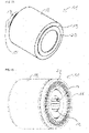
- FIG 1A an exemplary embodiment of a stator of the electric machine is shown.
- FIG 1B an exemplary embodiment of a stator connected to a power supply is shown.
- FIG 1A an exemplary embodiment of a stator 11 of an electric machine 10 is shown.
- the stator 11 comprises an iron stack 18 with at least one iron sheet in which slots 12 are inserted.
- electrically conductive bars 13 are arranged in the slots 12 .
- the bars 13 can for example comprise aluminum or copper.
- one electrically conductive bar 13 is arranged in each slot 12 .
- On a first side 19 of the stator 11 the bars 13 are electrically connected with each other by a short circuit ring 20.
- no short circuit ring 20 is arranged.
- the electrically conductive bars 13 in the slots 12 form an electrical winding 15 of the stator 11.
- the bars 13 can each be connected to a power supply 16 at the second side 21 of the stator 11.
- FIG 1B an exemplary embodiment of the stator 11 which is connected to the power supply 16 is shown.
- the bars 13 are each connected to a terminal of the power supply 16.
- the current in the bars 13 can be controlled by the power supply 16 either individually or in groups. This means each bar 13 forms an electrical phase n and can be supplied with an individual phase current I n for each electrical phase n.
- the bars 13 and also the slots 12 have a straight design and the slots 12 are parallel to each other. Furthermore, the slots 12 are arranged equidistant around the perimeter of the stator 11. Consequently, the production of the slots 12 and the bars 13 is simplified.
- a rotor 17 of the electric machine 10 can be arranged inside the stator 11. It is also possible that the rotor 17 of the electric machine 10 is arranged outside the stator 11. In both cases an air gap 14 is arranged between the stator 11 and the rotor 17.
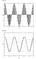
- phase currents I n for a stator 11 with 60 bars 13 are shown. Each of the bars 13 is supplied with an individual phase current I n at the instant of time depicted in figure 2A .
- the exemplary stator 11 comprises 60 electrical phases n.
- the phase currents I n are phase shifted towards each other and alternate with time.
- a rotating stator magnetic field is formed.
- the sum of all phase currents I n is zero in order to avoid leakage currents in the power supply.
- the phase currents I n are phase shifted in such a way that six different poles of the stator magnetic field are formed.
- the circumferential extent of the poles of the stator magnetic field is in this case given by the circumferential extent of the bars 13 which contribute to the formation of the respective pole.
- the six different poles all comprise the same circumferential extent along the air gap 14.
- FIG 2B the magneto motive force M along the air gap 14 is shown for the 60 bars 13.
- the magneto motive force M is generated by the phase currents I n of the stator 11. Therefore, the magneto motive force also alternates along the air gap 14.
- the magneto motive force M can exert torque on the rotor 17 which is arranged inside or outside the stator 11.
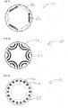
- FIG 2C a cross section of a rotor 17 with buried permanent magnets is shown.
- the rotor 17 comprises six magnets which is why the rotor magnetic field comprises six poles.
- the number of poles of the rotor magnetic field is given by the number of magnets of the rotor 17.
- all magnets of the rotor 17 have the same size, consequently, all poles of the rotor magnetic field have the same angular extent.
- FIG 2D a cross section through a rotor 17 which is a synchronous reluctance rotor is shown.
- the synchronous reluctance rotor is optimized for six magnetic poles which all have the same angular extent.
- FIG 2E a cross section through the rotor 17 which is a squirrel cage rotor is shown.
- the rotor 17 comprises slots 12 in which electrically conductive bars 13 are arranged.
- the slots 12 are arranged equidistant around the perimeter of the rotor 17.
- the bars 13 can for example comprise aluminum or copper.
- each slot 12 one electrically conductive bar 13 is arranged.
- the bars 13 are electrically connected with each other by a short circuit ring 20.
- FIG 3A the phase currents I n for the stator 11 with 60 bars 13 and therefore 60 electrical phases n are shown.
- the stator magnetic field again comprises six poles, however, in this case the circumferential extent of a first pole 22 is different from the circumferential extent of the other poles which are referred to as second poles 23.
- the difference in the circumferential extents between the first pole 22 and the second poles 23 is achieved by forming the first pole 22 with a larger number of bars 13 than the second poles 23. This means, a larger number of bars 13 contributes to the formation of the first pole 22 than to the formation of each of the second poles 23.
- the maximum amplitude of the phase currents I n that contribute to the formation of the first pole 22 is smaller than the maximum amplitudes of the phase currents I n that contribute to the formation of the second poles 23.
- the circumferential extents of the poles of the stator magnetic field can be changed by changing the phase currents I n . It is also possible to change the number of poles of the stator magnetic field by changing the phase currents I n . Therefore, it is possible to adapt the stator magnetic field in such a way that a rotor magnetic field of the rotor 17 of the electric machine 10 interacts with the stator magnetic field.
- FIG 3B the magneto motive force M along the air gap 14 is shown for the stator 11 which is supplied with the phase currents I n shown in figure 3A .
- a rotor 17 with a rotor magnetic field where the magnetic poles exhibit the same angular extents as the poles of the stator magnetic field can move relative to the stator 11 during operation of the electric machine 10.
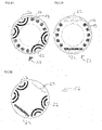
- FIG 3C a cross section through an exemplary embodiment of the rotor 17 is shown where the angular extents of the poles of the rotor magnetic field are different from each other.
- the poles of the rotor magnetic field are formed by buried permanent magnets. One of the buried magnets is larger than the other five magnets. Therefore, the rotor magnetic field comprises a first pole with an angular extent that is larger than the angular extents of the other poles, referred to as second poles.
- the rotor 17 depicted in figure 3C can be employed in an electric machine 10 with a stator 11 where the stator magnetic field is formed by the phase currents I n depicted in figure 3A . Since the angular extents of the poles of the stator magnetic field and the poles of the rotor magnetic field are equal the rotor 17 can rotate with a constant angular velocity during operation of the electric machine 10.
- FIG 3D a cross section through another exemplary embodiment of the rotor 17 is shown.
- the rotor 17 is a synchronous reluctance rotor with six magnetic poles. Similar to the rotor 17 shown in figure 3C a first pole of the rotor magnetic field comprises a larger angular extent than the other poles, referred to as second poles. Also this exemplary rotor 17 can be employed in an electric machine 10 with a stator 11 where the stator magnetic field is formed by the phase currents I n depicted in figure 3A .
- FIG 4A the phase currents I n for a stator 11 with six poles of the stator magnetic field are depicted.
- a first pole 22 and a third pole 24 have the same circumferential extent along the air gap 14, where the circumferential extent of the first pole 22 and the third pole 24 is larger the than circumferential extent of the four second poles 23.
- the first pole 22 and the third pole 24 are arranged symmetrically with respect to a center of a cross section through the stator 11.
- FIG 4B the magneto motive force M along the air gap 14 is shown for the stator 11 which is supplied with the phase currents I n shown in figure 4A .
- a rotor 17 with a rotor magnetic field where for each pole of the stator magnetic field the rotor magnetic field comprises a pole with the same angular extent can move relative to the stator 11 during operation of the electric machine 10.
- FIG 4C a cross section through a further exemplary embodiment of the rotor 17 is shown.
- the six magnetic poles of the rotor 17 are formed by buried permanent magnets where two of the magnets have a larger size than the other four magnets.
- the two magnets that have a larger size than the other magnets are arranged symmetrically with respect to the center of the rotor 17.
- the rotor magnetic field comprises a first pole, four second poles and a third pole, where the third pole has the same circumferential extent along the air gap 14 as the first pole. Therefore, the rotor 17 depicted in figure 4C can interact with a stator magnetic field which is formed by the phase currents I n shown in figure 4A .
- FIG 4D a cross section through a further exemplary embodiment of the rotor 17 is shown.
- the rotor 17 is a synchronous reluctance rotor which is optimized for six magnetic poles. Similar to the rotor 17 shown in figure 4C a first pole and a third pole of the rotor magnetic field comprise a larger angular extent than the four second poles. Also this exemplary rotor 17 can interact with the stator magnetic field which is formed by the phase currents I n shown in figure 4A .
- phase currents I n for a stator 11 with six poles is shown.
- a first pole 22 and a third pole 24 have a larger circumferential extent along the air gap 14 than the four second poles 23.
- the maximum amplitude of the phase currents I n is the same.
- the first pole 22 and the third pole 24 are arranged symmetrically with respect to the center of a cross section through the stator 11 also in this case the sum of the phase currents I n amounts to zero.
- the maximum current amplitude can be exploited.
- the magneto motive force M along the air gap 14 is shown for the stator 11 which is supplied with the phase currents I n shown in figure 5A .
- the rotor 17 can be a squirrel cage rotor since the number and the width of the magnetic poles of the rotor magnetic field are formed by induction from the stator magnetic field.
- FIG 6A cross section through an exemplary embodiment of a rotor 17 is shown.
- the rotor 17 is formed by a combination of a synchronous reluctance rotor and a squirrel cage rotor.
- Four first poles of the rotor magnetic field are formed by a part of a synchronous reluctance rotor and the rotor 17 further comprises eight slots 12 with electrically conductive bars 13.
- at least two second poles of the rotor magnetic field can be formed by induction from the stator magnetic field.
- the first poles and the slots 12 of the squirrel cage rotor are arranged symmetrically with respect to the center of the cross section through the rotor 17.
- the rotor 17 comprises a combination of a rotor for a synchronous electric machine and a rotor for an induction machine.
- FIG 6B a cross section through another exemplary embodiment of a rotor 17 is shown.
- the rotor 17 comprises two permanent magnets forming two first poles and ten slots with electrically conductive bars 13 of a squirrel cage rotor.
- the first poles and the slots 12 are arranged symmetrically with respect to the center of the cross section through the rotor 17.
- FIG 6C a cross section through another exemplary embodiment of a rotor 17 is shown.
- the rotor 17 comprises parts of a synchronous reluctance rotor forming four first poles and two permanent magnets forming two second poles.
- the poles of the rotor magnetic field are arranged symmetrically with respect to the center of the cross section through the rotor 17.
- the poles of the rotor magnetic field are not symmetric with respect to the center of the cross section through the rotor 17.
Landscapes
- Engineering & Computer Science (AREA)
- Power Engineering (AREA)
- Synchronous Machinery (AREA)
- Permanent Magnet Type Synchronous Machine (AREA)
- Permanent Field Magnets Of Synchronous Machinery (AREA)
Description
- The present invention relates to an electric machine with a stator and a rotor mounted movable relative to said stator.
- Electric machines can be operated as a motor or a generator. The stator comprises an electric winding, which can be formed by bars arranged in slots in the stator where the bars comprise an electrically conductive material. The winding is connected to a power supply, which often has multiple phases.
- If the electric machine is operated as a motor a stator magnetic field is formed in an air gap between the stator and the rotor by supplying the electric windings of the stator with different electrical phases by the power supply. The stator magnetic field changes with time such that a rotating magnetic field is formed. The stator magnetic field comprises several magnetic poles. In the rotor a rotor magnetic field is formed which interacts with the stator magnetic field. During operation of the electric machine torque is exerted on the rotor by the stator magnetic field and the rotor moves relative to the stator.
- However, for electric machines the power conversion efficiency is usually not optimized for all operating points of the electric machine. For example, the power conversion efficiency might not be optimized if the electric machine is operated in partial load.
- In "EVS28 International electric vehicle symposium and exhibition: Intelligent stator cage winding for automotive traction electric machines" by Gurakuq Dajaku et al. an electric machine with a stator is described. The winding of the stator is formed by massive conductors that are connected to a multiphase inverter.
- In
US 2016/173019 Al an electric machine is described. During operation the number of active phases of the stator can be adapted, wherein the active phases form groups of equal size. - It is an objective to provide an electric machine with an increased efficiency.
- This objective is solved by the independent claim. Further embodiments are the subject of dependent claims.
- In one embodiment of the electric machine the electric machine comprises a stator which comprises at least two slots. In the slots at least one electrically conductive bar is arranged, respectively. It is possible that the stator comprises a plurality of slots. The stator can further be formed by a plurality of iron sheets in which the slots are formed. It is also possible that several bars or different electrically conductive materials are arranged within a slot.
- In a preferred embodiment in each slot exactly one bar is arranged.
- In another preferred embodiment the bars have a straight design. As a result, both the production of the slots and the production of the bars are simplified. The bars can comprise aluminum or copper. The slots can be arranged equidistant around the perimeter of the stator and the slots can be parallel to each other. The bars are electrically connected to one another at a first side of the stator so that they produce a short circuit with one another.
- Furthermore, the stator is adjacent to an air gap. The air gap is arranged between the stator and a rotor of the electric machine.
- The at least two electrically conductive bars form an electric winding of the stator and are arranged to be supplied with a corresponding electrical phase, respectively, by a power supply. This means, the winding of the stator comprises at least two electrical phases which are formed by the bars. Preferably, the electric machine comprises multiple electrical phases. Each bar can be supplied with an individual phase current, respectively. The phase currents can be shifted time-wise towards each other such that a rotating magnetic field is formed in the air gap. The sum of all phase currents is equal to zero in order to avoid leakage currents in the power supply.
- The stator can be arranged similar to a squirrel cage rotor where the bars form a short circuit only on a first side of the stator, for example by forming a short circuit ring. At a second side of the stator which faces away from the first side the bars are each electrically connected with the power supply. Thus, the bars in the slots can be controlled individually or in groups by the power supply with a respective electrical phase.
- The stator is arranged in such a way that during operation of the electric machine a stator magnetic field with at least two magnetic poles is formed in the air gap, where at least a first pole has a circumferential extent along the air gap which is different from the circumferential extent of at least a second pole, wherein the stator magnetic field comprises at least the first pole and the second pole. During operation of the electric machine the bars of the winding of the stator are supplied with individual phase currents by the power supply. In this way the rotating stator magnetic field is formed in the air gap. As the phase currents are time-wise phase shifted towards each other, magnetic poles of the stator magnetic field are formed in the air gap which rotate along the air gap. If a rotor of the electric machine can interact with the stator magnetic field, torque can be exerted on the rotor. As the electric machine comprises at least two slots with electrically conductive bars the stator magnetic field comprises at least the first pole and the second pole.
- For each pole of the stator magnetic field the rotor magnetic field comprises a pole with the same angular extent and the stator magnetic field is a rotating magnetic field.
- The circumferential extent of a magnetic pole is given along the perimeter of the air gap. The circumferential extent can therefore be a geometrical extent along the perimeter of the air gap.
- In a preferred embodiment the stator has a circular shaped cross section. Thus, also the cross section through the air gap can be circular shaped. In this case, the circumferential extent of the magnetic poles can also be given by an angular extent. An angular extent is given within a cross section through the stator for a central angle of the cross section. This means, each magnetic pole extends within a certain angle range within a cross section through the stator. The angle range is measured as the opening angle of a segment of the circle in which the respective pole extends.
- The circumferential extent of the first pole can be larger than the circumferential extent of the second pole. It is also possible that the circumferential extent of the first pole is smaller than the circumferential extent of the second pole. Similarly, also the angular extent of the first pole can be either larger or smaller than the angular extent of the second pole.
- For synchronous electric machines the circumferential extents of the magnetic poles of the stator magnetic field can be chosen in such a way that a rotor magnetic field can interact with the stator magnetic field such that torque is exerted on the rotor. This means, the circumferential extents of the poles of the stator magnetic field are chosen in such a way that for each pole of the rotor magnetic field the stator magnetic field comprises a pole with the same angular extent.
- For asynchronous electric machines, also called induction machines, the circumferential extents of the magnetic poles of the stator magnetic field can be changed during the operation of the electric machine since the rotor magnetic field can interact with different stator magnetic fields.
- Advantageously, the circumferential extents of the poles of the rotor magnetic field and the stator magnetic field can be chosen in such a way that the electric machine is optimized for different operation modes. For example, the electric machine can be optimized for different partial load conditions. This means, the electric machine can be optimized for an increased power conversion efficiency or for an increased torque.
- Furthermore, the difference of the circumferential extents of the first and the second pole is advantageous for a measurement of an angular position of the rotor or the motor speed. The angular position of the rotor gives the position of the rotor with respect to the stator. For small motor speeds the angular position of the rotor can be determined without a sensor, for example by measuring the inductance of the electric winding of the stator by applying high-frequency currents and comparing the measured values to a look-up table. For larger motor speeds the angular position of the rotor can be determined by measuring the voltage which is induced in the winding of the stator during operation of the electric machine. In both cases the accuracy of determining the angular position of the rotor depends on the circumferential extent of the poles of the stator magnetic field. The angular position of the rotor can be determined with a higher accuracy if a larger number of bars in the stator contributes to the formation of a pole of the stator magnetic field. Thus, with at least one first pole having a larger circumferential extent than at least one second pole, the angular position of the rotor and the motor speed can be determined with an increased accuracy in comparison to an electric machine where all poles exhibit the same circumferential extents.
- In one embodiment of the electric machine the at least two poles have a respective pole width which is equal to their circumferential extents along the air gap. This means, the respective pole widths also correspond to the angular extents of the poles.
- In one embodiment of the electric machine the stator magnetic field is a rotating field. The electrical phases can be time-wise shifted towards each other such that the rotating stator magnetic field is formed in the air gap. During operation of the electric machine torque is exerted on the rotor by the stator magnetic field and the rotor moves relative to the stator.
- In one embodiment of the electric machine the electric machine comprises at least one further slot in the stator, in which at least one further electrically conductive bar is arranged, where at least one third pole of the stator magnetic field has the same circumferential extent along the air gap as the first pole. The circumferential extents of the first and the third pole can thus either be larger or smaller than the circumferential extent of the second pole.
- In one embodiment of the electric machine the first and the third pole are arranged symmetrically with respect to a center of a cross section through the stator. Preferably, the cross section of the stator is circular shaped and the cross section comprises a center in the center of the circle. This means, the first and the third pole can be arranged on opposing sides of the circle within the cross section through the stator. It is also possible that the electric machine comprises a fourth pole which has the same circumferential extent along the air gap as the second pole. In that case the second and the fourth pole can also be arranged symmetrically with respect to the center of the cross section through the stator. In another embodiment it is also possible that the electric machine comprises several first and third poles which are arranged symmetrically with respect to the center of the cross section through the stator.
- According to the invention the air gap is arranged between the stator and a rotor which is mounted movable relative to the stator. The stator and the rotor are both adjacent to the air gap such that the air gap is arranged between the rotor and the stator. The rotor can be arranged within the stator or around the stator. The rotor can be an asynchronously operating induction rotor or a synchronous rotor.
- A rotor magnetic field with magnetic poles is formed in the rotor during operation of the electric machine where the poles exhibit the same angular extents as the poles of the stator magnetic field in the air gap where the angular extents refer to central angles of a cross section through the rotor. The rotor can for example comprise permanent magnets which form the rotor magnetic field with several poles. It is also possible that the rotor is a squirrel cage rotor where the rotor magnetic field is induced by the stator magnetic field during operation of the electric machine. Preferably, the cross section of the rotor is circular shaped. In this case angular extents of the poles for central angles of the circle can be given. This means, each pole extends over a certain angle range of the circle.
- Since the cross section of the stator is preferably also circular shaped, the angular extents of the poles of the rotor magnetic field extend along the same central angles of the cross section as the poles of the stator magnetic field. This means the geometric size of the poles of the stator magnetic field can be different from the geometric size of the poles of the rotor magnetic field, however, for each pole of the stator magnetic field the rotor magnetic field comprises a pole with the same angular extent.
- If the rotor magnetic field is formed by permanent magnets in the rotor the number of the poles of the rotor magnetic field is given by the number of the permanent magnets in the rotor. The angular extents of the poles of the rotor magnetic field can in this case be changed by changing the geometric size of the permanent magnets.
- In one embodiment of the electric machine the rotor is a squirrel cage rotor. This means the rotor comprises slots in which electrically conductive bars are arranged where the bars form an electrical winding of the rotor. The bars are electrically connected at both sides of the rotor by short circuit rings and they can comprise aluminum or copper. In this embodiment the number and the angular extents of the poles of the rotor magnetic field can be changed during operation of the electric machine.
- In one embodiment of the electric machine the rotor is one of a rotor with buried permanent magnets, a rotor with surface mounted permanent magnets, a synchronous reluctance rotor, an externally excited synchronous rotor. In the case of a rotor with permanent magnets the number of the poles of the rotor magnetic field is given by the number of magnetic poles of the rotor and it cannot be changed during operation of the electric machine. In the case of the rotor with buried permanent magnets the permanent magnets can be arranged in different shapes within the rotor, for example v-shaped or as spokes.
- In one embodiment of the electric machine the rotor is a combination of at least two of a rotor with buried permanent magnets, a rotor with surface mounted permanent magnets, a synchronous reluctance rotor, an externally excited synchronous rotor, a squirrel cage rotor. This means the poles of the rotor magnetic field can for example be formed by permanent magnets and parts of a winding of a squirrel cage rotor. It is also possible to combine other types of rotors and it is further possible to combine more than two types of rotors. The different poles can be arranged either symmetrical or asymmetrical around the center through a cross section of the rotor.
- In one embodiment of the electric machine the stator magnetic field is formed by supplying the bars of the stator with a corresponding electrical phase each during operation of the electric machine. The electrical phases can be time-wise shifted towards each other such that the rotating stator magnetic field is formed in the air gap. By supplying the bars of the stator with a corresponding electrical phase it is possible to form the stator magnetic field with poles where the circumferential extent of the poles can be changed by changing the phase currents of the bars. Therefore, the number and the circumferential extents of the poles of the stator magnetic field can be adapted to the number and circumferential extents of the poles of the rotor magnetic field during operation of the electric machine.
- The feature that the circumferential extent and the number of the poles of the stator magnetic field can be changed during operation of the electric machine is realized by forming the electric winding of the stator with the bars arranged in the slots of the stator and supplying each bar with an individual phase current by means of the power supply. If the stator magnetic field was formed by permanent magnets or by an electrical winding where the pole widths of the stator magnetic field cannot be adapted during operation of the electric machine, it would not be possible to adapt the stator magnetic field to the properties of the rotor magnetic field.
- The following description of figures may further illustrate and explain exemplary embodiments. Components that are functionally identical or have an identical effect are denoted by identical references. Identical or effectively identical components might be described only with respect to the figures where they occur first. Their description is not necessarily repeated in successive figures.
- In
figure 1A an exemplary embodiment of a stator of the electric machine is shown. - In
figure 1B an exemplary embodiment of a stator connected to a power supply is shown. - In
figures 2A and 2B exemplary phase currents and the resulting magneto motive force of the stator are shown. - In
figures 2C to 2E cross sections through different rotors are shown. - In
figures 3A and 3B exemplary phase currents and the resulting magneto motive force for an exemplary embodiment of the stator are shown. - In
figures 3C and 3D cross sections through two exemplary embodiments of rotors are shown. - In
figures 4A and 4B exemplary phase currents and the resulting magneto motive force for another exemplary embodiment of the stator are shown. - In
figures 4C and 4D cross sections through two further exemplary embodiments of the rotor are shown. - In
figures 5A and 5B exemplary phase currents and the resulting magneto motive force are shown for another exemplary embodiment of the stator. - In
figures 6A to 6C cross sections through three further exemplary embodiments of the rotor are shown. - In
figure 1A an exemplary embodiment of astator 11 of anelectric machine 10 is shown. Thestator 11 comprises aniron stack 18 with at least one iron sheet in whichslots 12 are inserted. In theslots 12 electricallyconductive bars 13 are arranged. Thebars 13 can for example comprise aluminum or copper. In this embodiment in eachslot 12 one electricallyconductive bar 13 is arranged. On afirst side 19 of thestator 11 thebars 13 are electrically connected with each other by ashort circuit ring 20. At asecond side 21 of thestator 11 noshort circuit ring 20 is arranged. The electricallyconductive bars 13 in theslots 12 form an electrical winding 15 of thestator 11. Thebars 13 can each be connected to apower supply 16 at thesecond side 21 of thestator 11. - In
figure 1B an exemplary embodiment of thestator 11 which is connected to thepower supply 16 is shown. At thesecond side 21 of thestator 11 thebars 13 are each connected to a terminal of thepower supply 16. The current in thebars 13 can be controlled by thepower supply 16 either individually or in groups. This means each bar 13 forms an electrical phase n and can be supplied with an individual phase current In for each electrical phase n. - In this embodiment the
bars 13 and also theslots 12 have a straight design and theslots 12 are parallel to each other. Furthermore, theslots 12 are arranged equidistant around the perimeter of thestator 11. Consequently, the production of theslots 12 and thebars 13 is simplified. Arotor 17 of theelectric machine 10 can be arranged inside thestator 11. It is also possible that therotor 17 of theelectric machine 10 is arranged outside thestator 11. In both cases anair gap 14 is arranged between thestator 11 and therotor 17. - In
figure 2A the phase currents In for astator 11 with 60bars 13 are shown. Each of thebars 13 is supplied with an individual phase current In at the instant of time depicted infigure 2A . This means, theexemplary stator 11 comprises 60 electrical phases n. The phase currents In are phase shifted towards each other and alternate with time. Thus, a rotating stator magnetic field is formed. The sum of all phase currents In is zero in order to avoid leakage currents in the power supply. In this example the phase currents In are phase shifted in such a way that six different poles of the stator magnetic field are formed. The circumferential extent of the poles of the stator magnetic field is in this case given by the circumferential extent of thebars 13 which contribute to the formation of the respective pole. The six different poles all comprise the same circumferential extent along theair gap 14. - In
figure 2B the magneto motive force M along theair gap 14 is shown for the 60 bars 13. The magneto motive force M is generated by the phase currents In of thestator 11. Therefore, the magneto motive force also alternates along theair gap 14. The magneto motive force M can exert torque on therotor 17 which is arranged inside or outside thestator 11. - In
figure 2C a cross section of arotor 17 with buried permanent magnets is shown. Therotor 17 comprises six magnets which is why the rotor magnetic field comprises six poles. Thus, the number of poles of the rotor magnetic field is given by the number of magnets of therotor 17. In this case all magnets of therotor 17 have the same size, consequently, all poles of the rotor magnetic field have the same angular extent. - In
figure 2D a cross section through arotor 17 which is a synchronous reluctance rotor is shown. The synchronous reluctance rotor is optimized for six magnetic poles which all have the same angular extent. - In
figure 2E a cross section through therotor 17 which is a squirrel cage rotor is shown. Therotor 17 comprisesslots 12 in which electricallyconductive bars 13 are arranged. Theslots 12 are arranged equidistant around the perimeter of therotor 17. Furthermore, thebars 13 can for example comprise aluminum or copper. In this embodiment in eachslot 12 one electricallyconductive bar 13 is arranged. On both sides of therotor 17 thebars 13 are electrically connected with each other by ashort circuit ring 20. - In
figure 3A the phase currents In for thestator 11 with 60bars 13 and therefore 60 electrical phases n are shown. In this embodiment the stator magnetic field again comprises six poles, however, in this case the circumferential extent of afirst pole 22 is different from the circumferential extent of the other poles which are referred to assecond poles 23. The difference in the circumferential extents between thefirst pole 22 and thesecond poles 23 is achieved by forming thefirst pole 22 with a larger number ofbars 13 than thesecond poles 23. This means, a larger number ofbars 13 contributes to the formation of thefirst pole 22 than to the formation of each of thesecond poles 23. In order to keep the sum of the phase currents In zero the maximum amplitude of the phase currents In that contribute to the formation of thefirst pole 22 is smaller than the maximum amplitudes of the phase currents In that contribute to the formation of thesecond poles 23. - Advantageously, the circumferential extents of the poles of the stator magnetic field can be changed by changing the phase currents In. It is also possible to change the number of poles of the stator magnetic field by changing the phase currents In. Therefore, it is possible to adapt the stator magnetic field in such a way that a rotor magnetic field of the
rotor 17 of theelectric machine 10 interacts with the stator magnetic field. - In
figure 3B the magneto motive force M along theair gap 14 is shown for thestator 11 which is supplied with the phase currents In shown infigure 3A . Arotor 17 with a rotor magnetic field where the magnetic poles exhibit the same angular extents as the poles of the stator magnetic field can move relative to thestator 11 during operation of theelectric machine 10. - In
figure 3C a cross section through an exemplary embodiment of therotor 17 is shown where the angular extents of the poles of the rotor magnetic field are different from each other. The poles of the rotor magnetic field are formed by buried permanent magnets. One of the buried magnets is larger than the other five magnets. Therefore, the rotor magnetic field comprises a first pole with an angular extent that is larger than the angular extents of the other poles, referred to as second poles. Therotor 17 depicted infigure 3C can be employed in anelectric machine 10 with astator 11 where the stator magnetic field is formed by the phase currents In depicted infigure 3A . Since the angular extents of the poles of the stator magnetic field and the poles of the rotor magnetic field are equal therotor 17 can rotate with a constant angular velocity during operation of theelectric machine 10. - In
figure 3D a cross section through another exemplary embodiment of therotor 17 is shown. Therotor 17 is a synchronous reluctance rotor with six magnetic poles. Similar to therotor 17 shown infigure 3C a first pole of the rotor magnetic field comprises a larger angular extent than the other poles, referred to as second poles. Also thisexemplary rotor 17 can be employed in anelectric machine 10 with astator 11 where the stator magnetic field is formed by the phase currents In depicted infigure 3A . - In
figure 4A the phase currents In for astator 11 with six poles of the stator magnetic field are depicted. In this embodiment afirst pole 22 and athird pole 24 have the same circumferential extent along theair gap 14, where the circumferential extent of thefirst pole 22 and thethird pole 24 is larger the than circumferential extent of the foursecond poles 23. Moreover, thefirst pole 22 and thethird pole 24 are arranged symmetrically with respect to a center of a cross section through thestator 11. - In
figure 4B the magneto motive force M along theair gap 14 is shown for thestator 11 which is supplied with the phase currents In shown infigure 4A . Arotor 17 with a rotor magnetic field where for each pole of the stator magnetic field the rotor magnetic field comprises a pole with the same angular extent can move relative to thestator 11 during operation of theelectric machine 10. - In
figure 4C a cross section through a further exemplary embodiment of therotor 17 is shown. The six magnetic poles of therotor 17 are formed by buried permanent magnets where two of the magnets have a larger size than the other four magnets. The two magnets that have a larger size than the other magnets are arranged symmetrically with respect to the center of therotor 17. This means, the rotor magnetic field comprises a first pole, four second poles and a third pole, where the third pole has the same circumferential extent along theair gap 14 as the first pole. Therefore, therotor 17 depicted infigure 4C can interact with a stator magnetic field which is formed by the phase currents In shown infigure 4A . - In
figure 4D a cross section through a further exemplary embodiment of therotor 17 is shown. Therotor 17 is a synchronous reluctance rotor which is optimized for six magnetic poles. Similar to therotor 17 shown infigure 4C a first pole and a third pole of the rotor magnetic field comprise a larger angular extent than the four second poles. Also thisexemplary rotor 17 can interact with the stator magnetic field which is formed by the phase currents In shown infigure 4A . - In
figure 5A the phase currents In for astator 11 with six poles is shown. Similarly to the case shown infigure 4A afirst pole 22 and athird pole 24 have a larger circumferential extent along theair gap 14 than the foursecond poles 23. For all six poles the maximum amplitude of the phase currents In is the same. As thefirst pole 22 and thethird pole 24 are arranged symmetrically with respect to the center of a cross section through thestator 11 also in this case the sum of the phase currents In amounts to zero. Thus, for each of thebars 13 which form the electrical phases n the maximum current amplitude can be exploited. - In
figure 5B the magneto motive force M along theair gap 14 is shown for thestator 11 which is supplied with the phase currents In shown infigure 5A . For any of the phase currents In shown infigures 2A ,3A ,4A and5A and the respective magneto motive force M therotor 17 can be a squirrel cage rotor since the number and the width of the magnetic poles of the rotor magnetic field are formed by induction from the stator magnetic field. - In
figure 6A cross section through an exemplary embodiment of arotor 17 is shown. Therotor 17 is formed by a combination of a synchronous reluctance rotor and a squirrel cage rotor. Four first poles of the rotor magnetic field are formed by a part of a synchronous reluctance rotor and therotor 17 further comprises eightslots 12 with electricallyconductive bars 13. During operation of theelectric machine 10 at least two second poles of the rotor magnetic field can be formed by induction from the stator magnetic field. The first poles and theslots 12 of the squirrel cage rotor are arranged symmetrically with respect to the center of the cross section through therotor 17. This means therotor 17 comprises a combination of a rotor for a synchronous electric machine and a rotor for an induction machine. - In
figure 6B a cross section through another exemplary embodiment of arotor 17 is shown. In this case therotor 17 comprises two permanent magnets forming two first poles and ten slots with electricallyconductive bars 13 of a squirrel cage rotor. The first poles and theslots 12 are arranged symmetrically with respect to the center of the cross section through therotor 17. - In
figure 6C a cross section through another exemplary embodiment of arotor 17 is shown. Therotor 17 comprises parts of a synchronous reluctance rotor forming four first poles and two permanent magnets forming two second poles. The poles of the rotor magnetic field are arranged symmetrically with respect to the center of the cross section through therotor 17. However, it is also possible that the poles of the rotor magnetic field are not symmetric with respect to the center of the cross section through therotor 17. -
- 10:
- electric machine
- 11:
- stator
- 12:
- slot
- 13:
- bar
- 14:
- air gap
- 15:
- winding
- 16:
- power supply
- 17:
- rotor
- 18:
- iron stack
- 19:
- first side
- 20:
- short circuit ring
- 21:
- second side
- 22:
- first pole
- 23:
- second pole
- 24:
- third pole
- In:
- phase current
- M:
- magneto motive force
- n:
- electrical phase
Claims (9)
- Electric machine (10), comprising:- a stator (11), which comprises at least two slots (12) in which each at least one electrically conductive bar (13) is arranged, respectively, where- the stator (11) is adjacent to an air gap (14),- the at least two electrically conductive bars (13) form an electric winding (15) of the stator (11) and are arranged to be supplied with a corresponding electrical phase (n), respectively, by a power supply (16),- the stator (11) is arranged in such a way that during operation of the electric machine (10) a stator magnetic field with at least two magnetic poles is formed in the air gap (14),- the air gap (14) is arranged between the stator (11) and a rotor (17) which is mounted movable relative to the stator (11), and- the stator magnetic field is a rotating field,
characterized in that- at least a first pole (22) has a circumferential extent along the air gap (14) which is different from the circumferential extent of at least a second pole (23), wherein the stator magnetic field comprises at least the first pole (22) and the second pole (23), and- for each pole of the stator magnetic field the rotor magnetic field comprises a pole with the same angular extent. - Electric machine (10) according to claim 1, where the at least two poles have a respective pole width which is equal to their circumferential extents along the air gap (14).
- Electric machine (10) according to one of one of the preceding claims, which comprises at least one further slot (12) in the stator (11), in which at least one further electrically conductive bar (13) is arranged, where at least one third pole (24) of the stator magnetic field has the same circumferential extent along the air gap (14) as the first pole (22).
- Electric machine (10) according to claim 3, where the first and the third pole are arranged symmetrically with respect to a center of a cross section through the stator (11) .
- Electric machine (10) according to one of the preceding claims, where during operation of the electric machine (10) a rotor magnetic field with magnetic poles is formed in the rotor (17) where the poles exhibit the same angular extents as the poles of the stator magnetic field in the air gap (14) where the angular extents refer to central angles of a cross section through the rotor (17).
- Electric machine (10) according to one of the preceding claims, where the rotor (17) is a squirrel cage rotor.
- Electric machine (10) according to one of claims 1 to 5, where the rotor (17) is one of:- a rotor with buried permanent magnets,- a rotor with surface mounted permanent magnets,- a synchronous reluctance rotor,- an externally excited synchronous rotor.
- Electric machine (10) according to one of claims 1 to 5, where the rotor (17) is a combination of at least two of:- a rotor with buried permanent magnets,- a rotor with surface mounted permanent magnets,- a synchronous reluctance rotor,- an externally excited synchronous rotor,- a squirrel cage rotor.
- Electric machine (10) according to one of the preceding claims, where the stator magnetic field is formed by supplying the bars (13) of the stator (11) with a corresponding electrical phase (n) each during operation of the electric machine (10).
Priority Applications (4)
| Application Number | Priority Date | Filing Date | Title |
|---|---|---|---|
| EP16205839.0A EP3340438B1 (en) | 2016-12-21 | 2016-12-21 | Electric machine |
| US16/472,164 US11264853B2 (en) | 2016-12-21 | 2017-12-13 | Electric machine having a stator with magnetic poles of various circumferential extents |
| CN201780078668.XA CN110192332B (en) | 2016-12-21 | 2017-12-13 | Electric machine |
| PCT/EP2017/082684 WO2018114537A1 (en) | 2016-12-21 | 2017-12-13 | Electric machine |
Applications Claiming Priority (1)
| Application Number | Priority Date | Filing Date | Title |
|---|---|---|---|
| EP16205839.0A EP3340438B1 (en) | 2016-12-21 | 2016-12-21 | Electric machine |
Publications (2)
| Publication Number | Publication Date |
|---|---|
| EP3340438A1 EP3340438A1 (en) | 2018-06-27 |
| EP3340438B1 true EP3340438B1 (en) | 2022-08-10 |
Family
ID=57629359
Family Applications (1)
| Application Number | Title | Priority Date | Filing Date |
|---|---|---|---|
| EP16205839.0A Active EP3340438B1 (en) | 2016-12-21 | 2016-12-21 | Electric machine |
Country Status (4)
| Country | Link |
|---|---|
| US (1) | US11264853B2 (en) |
| EP (1) | EP3340438B1 (en) |
| CN (1) | CN110192332B (en) |
| WO (1) | WO2018114537A1 (en) |
Families Citing this family (2)
| Publication number | Priority date | Publication date | Assignee | Title |
|---|---|---|---|---|
| CN109617279B (en) * | 2019-01-18 | 2020-11-03 | 江苏大学 | A Modular Built-in Hybrid Permanent Magnet Motor Rotor Structure |
| DE102020104659A1 (en) * | 2020-02-21 | 2021-08-26 | Feaam Gmbh | Electrical machine and method for operating the electrical machine |
Family Cites Families (26)
| Publication number | Priority date | Publication date | Assignee | Title |
|---|---|---|---|---|
| JP3818340B2 (en) | 1997-09-26 | 2006-09-06 | 株式会社富士通ゼネラル | Permanent magnet motor |
| US6274960B1 (en) * | 1998-09-29 | 2001-08-14 | Kabushiki Kaisha Toshiba | Reluctance type rotating machine with permanent magnets |
| JP2000287395A (en) * | 1999-03-30 | 2000-10-13 | Toshiba Corp | Rotor of permanent magnet type reluctance type rotating electric machine |
| CN1458734A (en) * | 2003-05-28 | 2003-11-26 | 刘硕成 | Three phase AC permanent magnet synchronous motor |
| DE10394336D2 (en) | 2003-09-11 | 2006-07-27 | Siemens Ag | Electric machine with induction rotor |
| DE10352814A1 (en) * | 2003-11-12 | 2005-06-30 | Siemens Ag | Electric machine |
| US7095149B2 (en) * | 2004-05-26 | 2006-08-22 | Mitsumi Electric Co., Ltd. | Magnetization pattern of rotor magnet for stepping motor |
| JP4010319B2 (en) * | 2005-02-09 | 2007-11-21 | ダイキン工業株式会社 | Core and rotor, motor and compressor |
| JP4821770B2 (en) * | 2005-07-19 | 2011-11-24 | 株式会社デンソー | AC motor and its control device |
| US7550892B2 (en) * | 2005-10-03 | 2009-06-23 | Ut-Battelle, Llc | High slot utilization systems for electric machines |
| US20070159021A1 (en) | 2005-12-19 | 2007-07-12 | Emerson Electric Co. | Composite magnet structure for rotor |
| CN201118414Y (en) * | 2007-10-29 | 2008-09-17 | 深圳航天科技创新研究院 | Square wave three-phase brushless permanent magnet DC motor |
| JP2010045932A (en) * | 2008-08-15 | 2010-02-25 | Ihi Corp | Motor |
| US8536748B2 (en) | 2008-11-11 | 2013-09-17 | Ford Global Technologies, Llc | Permanent magnet machine with different pole arc angles |
| JP5556037B2 (en) * | 2009-03-26 | 2014-07-23 | 日産自動車株式会社 | Synchronous motor |
| JP5287824B2 (en) * | 2010-10-20 | 2013-09-11 | 株式会社デンソー | motor |
| CN201910684U (en) * | 2011-01-26 | 2011-07-27 | 巢湖顺枫风力发电科技有限公司 | Permanent magnet rotor of small/medium-sized generator |
| EP2509199A1 (en) * | 2011-04-08 | 2012-10-10 | Grundfos Management A/S | Rotor |
| US8633627B2 (en) * | 2011-08-30 | 2014-01-21 | General Electric Company | Electric machine |
| JP5875886B2 (en) * | 2012-02-08 | 2016-03-02 | 本田技研工業株式会社 | Rotating electric machine stator |
| JP6142601B2 (en) * | 2013-03-19 | 2017-06-07 | スズキ株式会社 | Reluctance motor |
| US10075105B2 (en) * | 2014-04-22 | 2018-09-11 | Baldor Electric Company | End ring and rotor bar for line start permanent magnet motor |
| DE102014105642A1 (en) * | 2014-04-22 | 2015-10-22 | Feaam Gmbh | Electric machine |
| DE102014118356A1 (en) * | 2014-12-10 | 2016-06-16 | Feaam Gmbh | Power unit and electrical machine |
| JP6191645B2 (en) * | 2015-03-31 | 2017-09-06 | トヨタ自動車株式会社 | Magnetless rotating electric machine |
| CN107852051B (en) * | 2015-07-21 | 2019-12-24 | 株式会社电装 | electric motor |
-
2016
- 2016-12-21 EP EP16205839.0A patent/EP3340438B1/en active Active
-
2017
- 2017-12-13 WO PCT/EP2017/082684 patent/WO2018114537A1/en not_active Ceased
- 2017-12-13 CN CN201780078668.XA patent/CN110192332B/en active Active
- 2017-12-13 US US16/472,164 patent/US11264853B2/en active Active
Also Published As
| Publication number | Publication date |
|---|---|
| US11264853B2 (en) | 2022-03-01 |
| US20190348883A1 (en) | 2019-11-14 |
| CN110192332A (en) | 2019-08-30 |
| EP3340438A1 (en) | 2018-06-27 |
| CN110192332B (en) | 2021-12-21 |
| WO2018114537A1 (en) | 2018-06-28 |
Similar Documents
| Publication | Publication Date | Title |
|---|---|---|
| US6051904A (en) | Rotary electric machine, especially an alternator for a motor vehicle | |
| JP5948061B2 (en) | Rotating electric machine and vehicle equipped with the rotating electric machine | |
| KR101729196B1 (en) | Multi-phase stator device | |
| US20130207500A1 (en) | Three-phase alternating current permanent magnet motor | |
| WO2008044020A1 (en) | Improvements in and relating to electromotive machines | |
| US7638917B2 (en) | Electrical rotating machine | |
| JP6227712B2 (en) | Rotating electric machine and vehicle equipped with the rotating electric machine | |
| US20170040855A1 (en) | Rotor for a rotary electric machine | |
| US9000648B2 (en) | Asymmetrical reluctance machine | |
| US4135107A (en) | Multi-phase alternating current machine with stepped stator | |
| JP2015509697A (en) | Synchronous electrical machine | |
| GB2508416A (en) | Reducing dominant undesirable harmonics in an electric machine | |
| CN107787543B (en) | Permanently excited motors with optimized geometry | |
| CN101060269B (en) | Electrical machines with reduced cogging | |
| US20160141923A1 (en) | Rotor for a reluctance motor, in particular a synchronous reluctance motor, method for producing such a rotor, and reluctance motor comprising such a rotor | |
| US11264853B2 (en) | Electric machine having a stator with magnetic poles of various circumferential extents | |
| CN108712045B (en) | Synchronous switch reluctance motor | |
| US20100052460A1 (en) | Electrical rotating machine | |
| CN114846724A (en) | Synchronous reluctance machine with variable air gap | |
| EP4742516A1 (en) | Dc motor having multi-phase armature winding coil wired to stator in independent and parallel manner, rotor having multiple permanent magnets, and coil wound in parallel according to pole of rotor | |
| US11196307B2 (en) | Electromagnetic assembly of polyphase structure | |
| CN108702039B (en) | Asynchronous motor | |
| EP4068573A1 (en) | A cogging electric machine and a method of operating the cogging electric machine | |
| US20140306567A1 (en) | Tandem rotor servo motor | |
| RU2283527C2 (en) | Low-speed induction motor |
Legal Events
| Date | Code | Title | Description |
|---|---|---|---|
| PUAI | Public reference made under article 153(3) epc to a published international application that has entered the european phase |
Free format text: ORIGINAL CODE: 0009012 |
|
| STAA | Information on the status of an ep patent application or granted ep patent |
Free format text: STATUS: THE APPLICATION HAS BEEN PUBLISHED |
|
| AK | Designated contracting states |
Kind code of ref document: A1 Designated state(s): AL AT BE BG CH CY CZ DE DK EE ES FI FR GB GR HR HU IE IS IT LI LT LU LV MC MK MT NL NO PL PT RO RS SE SI SK SM TR |
|
| AX | Request for extension of the european patent |
Extension state: BA ME |
|
| STAA | Information on the status of an ep patent application or granted ep patent |
Free format text: STATUS: REQUEST FOR EXAMINATION WAS MADE |
|
| 17P | Request for examination filed |
Effective date: 20181218 |
|
| RBV | Designated contracting states (corrected) |
Designated state(s): AL AT BE BG CH CY CZ DE DK EE ES FI FR GB GR HR HU IE IS IT LI LT LU LV MC MK MT NL NO PL PT RO RS SE SI SK SM TR |
|
| STAA | Information on the status of an ep patent application or granted ep patent |
Free format text: STATUS: EXAMINATION IS IN PROGRESS |
|
| 17Q | First examination report despatched |
Effective date: 20200207 |
|
| RIC1 | Information provided on ipc code assigned before grant |
Ipc: H02K 3/28 20060101AFI20200915BHEP Ipc: H02K 1/27 20060101ALN20200915BHEP |
|
| RAP1 | Party data changed (applicant data changed or rights of an application transferred) |
Owner name: MOLABO GMBH |
|
| RIC1 | Information provided on ipc code assigned before grant |
Ipc: H02K 1/276 20220101ALN20220110BHEP Ipc: H02K 3/28 20060101AFI20220110BHEP |
|
| RIC1 | Information provided on ipc code assigned before grant |
Ipc: H02K 1/276 20220101ALN20220118BHEP Ipc: H02K 3/28 20060101AFI20220118BHEP |
|
| GRAP | Despatch of communication of intention to grant a patent |
Free format text: ORIGINAL CODE: EPIDOSNIGR1 |
|
| STAA | Information on the status of an ep patent application or granted ep patent |
Free format text: STATUS: GRANT OF PATENT IS INTENDED |
|
| RIC1 | Information provided on ipc code assigned before grant |
Ipc: H02K 1/276 20220101ALN20220124BHEP Ipc: H02K 3/28 20060101AFI20220124BHEP |
|
| RIC1 | Information provided on ipc code assigned before grant |
Ipc: H02K 1/276 20220101ALN20220128BHEP Ipc: H02K 3/28 20060101AFI20220128BHEP |
|
| GRAJ | Information related to disapproval of communication of intention to grant by the applicant or resumption of examination proceedings by the epo deleted |
Free format text: ORIGINAL CODE: EPIDOSDIGR1 |
|
| INTG | Intention to grant announced |
Effective date: 20220301 |
|
| STAA | Information on the status of an ep patent application or granted ep patent |
Free format text: STATUS: EXAMINATION IS IN PROGRESS |
|
| INTC | Intention to grant announced (deleted) | ||
| GRAP | Despatch of communication of intention to grant a patent |
Free format text: ORIGINAL CODE: EPIDOSNIGR1 |
|
| STAA | Information on the status of an ep patent application or granted ep patent |
Free format text: STATUS: GRANT OF PATENT IS INTENDED |
|
| RIC1 | Information provided on ipc code assigned before grant |
Ipc: H02K 1/276 20220101ALN20220419BHEP Ipc: H02K 3/28 20060101AFI20220419BHEP |
|
| INTG | Intention to grant announced |
Effective date: 20220517 |
|
| GRAS | Grant fee paid |
Free format text: ORIGINAL CODE: EPIDOSNIGR3 |
|
| GRAA | (expected) grant |
Free format text: ORIGINAL CODE: 0009210 |
|
| STAA | Information on the status of an ep patent application or granted ep patent |
Free format text: STATUS: THE PATENT HAS BEEN GRANTED |
|
| AK | Designated contracting states |
Kind code of ref document: B1 Designated state(s): AL AT BE BG CH CY CZ DE DK EE ES FI FR GB GR HR HU IE IS IT LI LT LU LV MC MK MT NL NO PL PT RO RS SE SI SK SM TR |
|
| REG | Reference to a national code |
Ref country code: AT Ref legal event code: REF Ref document number: 1511290 Country of ref document: AT Kind code of ref document: T Effective date: 20220815 Ref country code: CH Ref legal event code: EP |
|
| REG | Reference to a national code |
Ref country code: DE Ref legal event code: R096 Ref document number: 602016074116 Country of ref document: DE |
|
| REG | Reference to a national code |
Ref country code: IE Ref legal event code: FG4D |
|
| REG | Reference to a national code |
Ref country code: NL Ref legal event code: MP Effective date: 20220810 |
|
| REG | Reference to a national code |
Ref country code: LT Ref legal event code: MG9D |
|
| PG25 | Lapsed in a contracting state [announced via postgrant information from national office to epo] |
Ref country code: SE Free format text: LAPSE BECAUSE OF FAILURE TO SUBMIT A TRANSLATION OF THE DESCRIPTION OR TO PAY THE FEE WITHIN THE PRESCRIBED TIME-LIMIT Effective date: 20220810 Ref country code: RS Free format text: LAPSE BECAUSE OF FAILURE TO SUBMIT A TRANSLATION OF THE DESCRIPTION OR TO PAY THE FEE WITHIN THE PRESCRIBED TIME-LIMIT Effective date: 20220810 Ref country code: PT Free format text: LAPSE BECAUSE OF FAILURE TO SUBMIT A TRANSLATION OF THE DESCRIPTION OR TO PAY THE FEE WITHIN THE PRESCRIBED TIME-LIMIT Effective date: 20221212 Ref country code: NO Free format text: LAPSE BECAUSE OF FAILURE TO SUBMIT A TRANSLATION OF THE DESCRIPTION OR TO PAY THE FEE WITHIN THE PRESCRIBED TIME-LIMIT Effective date: 20221110 Ref country code: NL Free format text: LAPSE BECAUSE OF FAILURE TO SUBMIT A TRANSLATION OF THE DESCRIPTION OR TO PAY THE FEE WITHIN THE PRESCRIBED TIME-LIMIT Effective date: 20220810 Ref country code: LV Free format text: LAPSE BECAUSE OF FAILURE TO SUBMIT A TRANSLATION OF THE DESCRIPTION OR TO PAY THE FEE WITHIN THE PRESCRIBED TIME-LIMIT Effective date: 20220810 Ref country code: LT Free format text: LAPSE BECAUSE OF FAILURE TO SUBMIT A TRANSLATION OF THE DESCRIPTION OR TO PAY THE FEE WITHIN THE PRESCRIBED TIME-LIMIT Effective date: 20220810 Ref country code: FI Free format text: LAPSE BECAUSE OF FAILURE TO SUBMIT A TRANSLATION OF THE DESCRIPTION OR TO PAY THE FEE WITHIN THE PRESCRIBED TIME-LIMIT Effective date: 20220810 |
|
| REG | Reference to a national code |
Ref country code: AT Ref legal event code: MK05 Ref document number: 1511290 Country of ref document: AT Kind code of ref document: T Effective date: 20220810 |
|
| PG25 | Lapsed in a contracting state [announced via postgrant information from national office to epo] |
Ref country code: PL Free format text: LAPSE BECAUSE OF FAILURE TO SUBMIT A TRANSLATION OF THE DESCRIPTION OR TO PAY THE FEE WITHIN THE PRESCRIBED TIME-LIMIT Effective date: 20220810 Ref country code: IS Free format text: LAPSE BECAUSE OF FAILURE TO SUBMIT A TRANSLATION OF THE DESCRIPTION OR TO PAY THE FEE WITHIN THE PRESCRIBED TIME-LIMIT Effective date: 20221210 Ref country code: HR Free format text: LAPSE BECAUSE OF FAILURE TO SUBMIT A TRANSLATION OF THE DESCRIPTION OR TO PAY THE FEE WITHIN THE PRESCRIBED TIME-LIMIT Effective date: 20220810 Ref country code: GR Free format text: LAPSE BECAUSE OF FAILURE TO SUBMIT A TRANSLATION OF THE DESCRIPTION OR TO PAY THE FEE WITHIN THE PRESCRIBED TIME-LIMIT Effective date: 20221111 |
|
| PG25 | Lapsed in a contracting state [announced via postgrant information from national office to epo] |
Ref country code: SM Free format text: LAPSE BECAUSE OF FAILURE TO SUBMIT A TRANSLATION OF THE DESCRIPTION OR TO PAY THE FEE WITHIN THE PRESCRIBED TIME-LIMIT Effective date: 20220810 Ref country code: RO Free format text: LAPSE BECAUSE OF FAILURE TO SUBMIT A TRANSLATION OF THE DESCRIPTION OR TO PAY THE FEE WITHIN THE PRESCRIBED TIME-LIMIT Effective date: 20220810 Ref country code: ES Free format text: LAPSE BECAUSE OF FAILURE TO SUBMIT A TRANSLATION OF THE DESCRIPTION OR TO PAY THE FEE WITHIN THE PRESCRIBED TIME-LIMIT Effective date: 20220810 Ref country code: DK Free format text: LAPSE BECAUSE OF FAILURE TO SUBMIT A TRANSLATION OF THE DESCRIPTION OR TO PAY THE FEE WITHIN THE PRESCRIBED TIME-LIMIT Effective date: 20220810 Ref country code: CZ Free format text: LAPSE BECAUSE OF FAILURE TO SUBMIT A TRANSLATION OF THE DESCRIPTION OR TO PAY THE FEE WITHIN THE PRESCRIBED TIME-LIMIT Effective date: 20220810 Ref country code: AT Free format text: LAPSE BECAUSE OF FAILURE TO SUBMIT A TRANSLATION OF THE DESCRIPTION OR TO PAY THE FEE WITHIN THE PRESCRIBED TIME-LIMIT Effective date: 20220810 |
|
| REG | Reference to a national code |
Ref country code: DE Ref legal event code: R097 Ref document number: 602016074116 Country of ref document: DE |
|
| PG25 | Lapsed in a contracting state [announced via postgrant information from national office to epo] |
Ref country code: SK Free format text: LAPSE BECAUSE OF FAILURE TO SUBMIT A TRANSLATION OF THE DESCRIPTION OR TO PAY THE FEE WITHIN THE PRESCRIBED TIME-LIMIT Effective date: 20220810 Ref country code: EE Free format text: LAPSE BECAUSE OF FAILURE TO SUBMIT A TRANSLATION OF THE DESCRIPTION OR TO PAY THE FEE WITHIN THE PRESCRIBED TIME-LIMIT Effective date: 20220810 |
|
| PLBE | No opposition filed within time limit |
Free format text: ORIGINAL CODE: 0009261 |
|
| STAA | Information on the status of an ep patent application or granted ep patent |
Free format text: STATUS: NO OPPOSITION FILED WITHIN TIME LIMIT |
|
| PG25 | Lapsed in a contracting state [announced via postgrant information from national office to epo] |
Ref country code: AL Free format text: LAPSE BECAUSE OF FAILURE TO SUBMIT A TRANSLATION OF THE DESCRIPTION OR TO PAY THE FEE WITHIN THE PRESCRIBED TIME-LIMIT Effective date: 20220810 |
|
| 26N | No opposition filed |
Effective date: 20230511 |
|
| REG | Reference to a national code |
Ref country code: CH Ref legal event code: PL |
|
| REG | Reference to a national code |
Ref country code: BE Ref legal event code: MM Effective date: 20221231 |
|
| PG25 | Lapsed in a contracting state [announced via postgrant information from national office to epo] |
Ref country code: SI Free format text: LAPSE BECAUSE OF FAILURE TO SUBMIT A TRANSLATION OF THE DESCRIPTION OR TO PAY THE FEE WITHIN THE PRESCRIBED TIME-LIMIT Effective date: 20220810 Ref country code: LU Free format text: LAPSE BECAUSE OF NON-PAYMENT OF DUE FEES Effective date: 20221221 |
|
| PG25 | Lapsed in a contracting state [announced via postgrant information from national office to epo] |
Ref country code: LI Free format text: LAPSE BECAUSE OF NON-PAYMENT OF DUE FEES Effective date: 20221231 Ref country code: IE Free format text: LAPSE BECAUSE OF NON-PAYMENT OF DUE FEES Effective date: 20221221 Ref country code: CH Free format text: LAPSE BECAUSE OF NON-PAYMENT OF DUE FEES Effective date: 20221231 |
|
| PG25 | Lapsed in a contracting state [announced via postgrant information from national office to epo] |
Ref country code: BE Free format text: LAPSE BECAUSE OF NON-PAYMENT OF DUE FEES Effective date: 20221231 |
|
| PG25 | Lapsed in a contracting state [announced via postgrant information from national office to epo] |
Ref country code: HU Free format text: LAPSE BECAUSE OF FAILURE TO SUBMIT A TRANSLATION OF THE DESCRIPTION OR TO PAY THE FEE WITHIN THE PRESCRIBED TIME-LIMIT; INVALID AB INITIO Effective date: 20161221 |
|
| PG25 | Lapsed in a contracting state [announced via postgrant information from national office to epo] |
Ref country code: CY Free format text: LAPSE BECAUSE OF FAILURE TO SUBMIT A TRANSLATION OF THE DESCRIPTION OR TO PAY THE FEE WITHIN THE PRESCRIBED TIME-LIMIT Effective date: 20220810 |
|
| PG25 | Lapsed in a contracting state [announced via postgrant information from national office to epo] |
Ref country code: MK Free format text: LAPSE BECAUSE OF FAILURE TO SUBMIT A TRANSLATION OF THE DESCRIPTION OR TO PAY THE FEE WITHIN THE PRESCRIBED TIME-LIMIT Effective date: 20220810 Ref country code: IT Free format text: LAPSE BECAUSE OF FAILURE TO SUBMIT A TRANSLATION OF THE DESCRIPTION OR TO PAY THE FEE WITHIN THE PRESCRIBED TIME-LIMIT Effective date: 20220810 |
|
| PG25 | Lapsed in a contracting state [announced via postgrant information from national office to epo] |
Ref country code: MC Free format text: LAPSE BECAUSE OF FAILURE TO SUBMIT A TRANSLATION OF THE DESCRIPTION OR TO PAY THE FEE WITHIN THE PRESCRIBED TIME-LIMIT Effective date: 20220810 |
|
| PG25 | Lapsed in a contracting state [announced via postgrant information from national office to epo] |
Ref country code: MC Free format text: LAPSE BECAUSE OF FAILURE TO SUBMIT A TRANSLATION OF THE DESCRIPTION OR TO PAY THE FEE WITHIN THE PRESCRIBED TIME-LIMIT Effective date: 20220810 |
|
| PG25 | Lapsed in a contracting state [announced via postgrant information from national office to epo] |
Ref country code: BG Free format text: LAPSE BECAUSE OF FAILURE TO SUBMIT A TRANSLATION OF THE DESCRIPTION OR TO PAY THE FEE WITHIN THE PRESCRIBED TIME-LIMIT Effective date: 20220810 |
|
| PG25 | Lapsed in a contracting state [announced via postgrant information from national office to epo] |
Ref country code: MT Free format text: LAPSE BECAUSE OF FAILURE TO SUBMIT A TRANSLATION OF THE DESCRIPTION OR TO PAY THE FEE WITHIN THE PRESCRIBED TIME-LIMIT Effective date: 20220810 |
|
| PG25 | Lapsed in a contracting state [announced via postgrant information from national office to epo] |
Ref country code: TR Free format text: LAPSE BECAUSE OF FAILURE TO SUBMIT A TRANSLATION OF THE DESCRIPTION OR TO PAY THE FEE WITHIN THE PRESCRIBED TIME-LIMIT Effective date: 20220810 |
|
| PGFP | Annual fee paid to national office [announced via postgrant information from national office to epo] |
Ref country code: GB Payment date: 20251218 Year of fee payment: 10 |
|
| PGFP | Annual fee paid to national office [announced via postgrant information from national office to epo] |
Ref country code: FR Payment date: 20251217 Year of fee payment: 10 |
|
| PGFP | Annual fee paid to national office [announced via postgrant information from national office to epo] |
Ref country code: DE Payment date: 20251219 Year of fee payment: 10 |