EP3340408A1 - An electrically conductive bar fitted with a tie and/or a strut - Google Patents
An electrically conductive bar fitted with a tie and/or a strut Download PDFInfo
- Publication number
- EP3340408A1 EP3340408A1 EP16206314.3A EP16206314A EP3340408A1 EP 3340408 A1 EP3340408 A1 EP 3340408A1 EP 16206314 A EP16206314 A EP 16206314A EP 3340408 A1 EP3340408 A1 EP 3340408A1
- Authority
- EP
- European Patent Office
- Prior art keywords
- bar
- tie
- strut
- longitudinal axis
- casing
- Prior art date
- Legal status (The legal status is an assumption and is not a legal conclusion. Google has not performed a legal analysis and makes no representation as to the accuracy of the status listed.)
- Withdrawn
Links
Images


Classifications
-
- H—ELECTRICITY
- H02—GENERATION; CONVERSION OR DISTRIBUTION OF ELECTRIC POWER
- H02G—INSTALLATION OF ELECTRIC CABLES OR LINES, OR OF COMBINED OPTICAL AND ELECTRIC CABLES OR LINES
- H02G5/00—Installations of bus-bars
- H02G5/06—Totally-enclosed installations, e.g. in metal casings
- H02G5/066—Devices for maintaining distance between conductor and enclosure
-
- H—ELECTRICITY
- H02—GENERATION; CONVERSION OR DISTRIBUTION OF ELECTRIC POWER
- H02G—INSTALLATION OF ELECTRIC CABLES OR LINES, OR OF COMBINED OPTICAL AND ELECTRIC CABLES OR LINES
- H02G5/00—Installations of bus-bars
-
- H—ELECTRICITY
- H02—GENERATION; CONVERSION OR DISTRIBUTION OF ELECTRIC POWER
- H02G—INSTALLATION OF ELECTRIC CABLES OR LINES, OR OF COMBINED OPTICAL AND ELECTRIC CABLES OR LINES
- H02G5/00—Installations of bus-bars
- H02G5/06—Totally-enclosed installations, e.g. in metal casings
- H02G5/063—Totally-enclosed installations, e.g. in metal casings filled with oil or gas
Definitions
- the invention relates to a medium- or high-voltage line for conducting electricity in a gas-insulated substation.
- Such a substation comprises electrical equipment of the disconnector, circuit breaker, or transformer type.
- Such electrical equipment is surrounded by a leaktight casing containing a dielectric gas such as SF 6 in order to be electrically insulated from the environment outside the casing.
- a dielectric gas such as SF 6
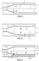
- Figure 1 shows a portion of a medium- or high-voltage electricity conduction line 1 comprising an electrically conductive bar 3 and a casing 2 of electrically conductive material surrounding the bar 3.
- the bar 3 has a top portion 33 and a bottom portion 35 that are situated above and below its longitudinal axis 4 when it is in service in the line 1.
- the bar 3 deforms in bending under the effect of its own weight, as shown in Figure 2 .
- the distance d between the bar 3 and the casing 2 is then reduced in the central region of the bar, such that the bottom portion 35 of the bar 3 comes too close to the casing 2. There is then an increased risk of a short circuit between the bar 3 and the casing 2.
- the invention seeks to remedy that drawback.
- the invention provides an electrically conductive bar extending around a longitudinal axis for inserting in a casing surrounding the bar, the bar having a top portion and a bottom portion situated above and below the longitudinal axis, the bar being characterized in that it is provided in the bottom portion with at least one tie oriented longitudinally and arranged to reduce the bending of the bar under the effect of its own weight; and/or in that it is provided in the top portion with at least one strut for reducing the bending of the bar under the effect of its own weight.
- the deformation of the bar by the tie and/or by the strut reduces the bending of the bar under the effect of its own weight in order to hold it far enough away from its casing. The risk of a short circuit between the bar and the casing is thus reduced.
- the force exerted by the tie and/or by the strut on the bar is easier to adjust than adjusting an arching force on the bar in order to deform it plastically prior to inserting it in the casing so as to reduce its bending under the effect of its own weight.
- the invention also provides a hollow bar, the tie and/or the strut being situated inside the bar.
- the invention also provides a bar wherein a guide configured to hold the tie and/or the strut along the longitudinal axis against the bar.
- the invention also provides a bar wherein the guide comprises guide blocks secured to the casing and spaced apart from one another along the longitudinal axis.
- the invention also provides a bar wherein the guide extends continuously with the bar along the longitudinal axis.
- the invention also provides a bar wherein the tie and/or the strut comprises a rod extending along the longitudinal axis.
- the invention also provides a bar wherein the tie comprises a cable.
- the invention also provides a bar wherein the tie includes at least one wheel around which the cable is wound, the cable being fastened to the bar at each of its opposite ends.
- the wheel serves to vary the length of the cable as a function of the temperature of the bar.
- the wheel is particularly useful when the cable is made of a material having a coefficient of thermal expansion that is less than that of the material of the bar.
- the invention also provides a portion of an electricity conduction line comprising a bar as defined above, together with a casing extending along the longitudinal axis and surrounding the bar.
- the invention also provides a method of manufacturing a portion of an electricity conduction line as defined above, wherein the tie and/or the strut is/are prestressed prior to being inserted in the casing in order to reduce the bending of the bar under the effect of its own weight when it is in the casing.
- Figure 3 shows a portion of an electricity conduction line 1 comprising an electrically conductive bar 3 for conveying medium- or high-voltage electricity within a gas-insulated substation (not shown).
- the conductive line 1 comprises a casing 2 surrounding the conductive bar 3.
- the casing 2 contains a dielectric gas, such as SF 6 .
- the casing 2 is in the shape of a cylindrical tube around a longitudinal axis 4.
- the conductive bar 3 is also substantially a body of revolution about the longitudinal axis 4.
- the bar 3 has a top portion 33 and a bottom portion 35 that are situated above and below the longitudinal axis 4, when the bar 3 is in its service position in the electricity conduction line 1.
- the bar 3 has a body 30 extended at its first end by a first endpiece and extended at its opposite second end opposite from the first end by a second endpiece, the first endpiece being given reference 31 in Figure 3 .
- the body 30 is a hollow cylinder arranged coaxially in the casing 2 about the longitudinal axis 4.
- the first endpiece 31 has a funnel-shaped portion 36 and a first connection portion 38 that are both bodies of revolution about the longitudinal axis 4.
- the funnel-shaped portion 36 is situated between the body 30 and the connection portion 38.
- connection portion 38 serves to connect the bar 3 electrically to another bar or to other electrical equipment of the gas-insulated substation.
- the first endpiece 31 In its bottom portion 35 only, the first endpiece 31 also has a plane portion 34 and a rim 32.
- the plane portion 34 is situated between the rim 32 and the funnel-shaped portion 36.
- the rim 32 is oriented normally to the longitudinal axis 4.
- the second endpiece is of the same type and of the same structure as the first endpiece 31.
- the tie 5 is situated inside the body 30 and it runs along the inside face of the body 30 along the longitudinal axis 4.
- first end 50 that passes through the first endpiece 31 via the rim 32.
- This first end 50 has a thread. It is clamped against the rim 32 by a nut 51.
- the nut 51 forms an element for retaining the tie relative to the bar 3.
- the tie 5 has a second end, opposite from the first end 50 along the axis 4, that has the same structure as the first end 50 and that is fastened to the second endpiece in analogous manner. The tie 5 is thus held at each of its ends relative to the bar 3.
- the tie 5 is put under tension at its ends in order to exert a compression force on the bottom portion 35 of the bar so as to reduce its bending under its own weight. In reaction, the bar 3 exerts a traction force on the tie 5.
- the tie 5 is a rod 52. It is held against the inside face of the body 30 by a series of blocks 61 spaced about the longitudinal axis 4 and acting as a guide 6 for guiding the rod 52 relative to the bar 3.
- the tie 5 deforms the bar 3 so as to compress its bottom portion 35, thereby tending to shorten the length L 2 of the bottom portion 35 compared with the length L 1 if the top portion 33.
- the central portion of the bar then tends to rise under the effect of the tension in the tie 5, opposing the bending of the bar 3 due to its own weight.
- the tie 5 is prestressed by the rim 32 against which the nut 51 is tightened, which tightening may be performed before the bar 3 is inserted in the casing 2.
- the line 1 has substantially the same structure as the line of the first embodiment.
- the body 30 nevertheless includes a profile 62 forming a tunnel relative to the remainder of the body 30 for housing the tie 5, as a replacement for the blocks 61.
- the profile 62 is fabricated integrally with the body 30, in particular by extrusion.
- the profile 62 defines a housing 63 extending along the longitudinal axis 4, and in which the tie 5 is guided along the body 30.
- the first endpiece 31 has neither the rim for co-operating with the nut 51 nor a plane portion.
- the other endpiece is of structure analogous to the structure of the first endpiece 31.
- the nut 51 holds the tie 5 at its first end 50 by bearing against a first end of the profile 62.
- the tie 5 is held at its second end in the same manner as at its first end 50.
- the line 1 has substantially the same structure as that of the line of the first embodiment, however the tie 5 comprises a cable 54.
- This cable 54 extends from the first end of the body 30 to which it is fastened, to the second end of the body (not shown), to which it is also fastened.
- the cable 52 is held at both ends of the body 30 along the longitudinal axis 4 and it is put under tension in order to reduce the bending of the bar 3.
- the two free ends of the cable 54 may be provided with threaded tips that are clamped to the body 30 by means of respective nuts 51.
- the cable 52 is wound around a first wheel 64 and a second wheel 65.
- the cable 52 has a bottom strand that extends from the first end of the cable 52 to the bottom portion of the first wheel 64 and on the bottom portion of the second wheel 65, prior to being wound around the second wheel 65 so as to form a top strand that extends towards the first wheel 64, around which it is also wound.
- the cable 52 then goes to the second end of the body.
- the cable 52 is made of a material presenting a coefficient of thermal expansion that is less than that of the material constituting the bar 3.
- the wheel 64 is fastened to the body 30 by a support 55. It acts as a pulley relative to the cable 54. Likewise, the second wheel 65 is fastened by a support 55 to the body.
- the wheels 64 and 65 serve to vary the length of the cable 52 as a function of temperature. They avoid excessive arching of the bar 3 as a result of differential expansion of the bar 3 and of the cable 52.
- the first endpiece 31 has a connection portion 38 and a funnel-shaped portion 36, a plane portion 34 and a rim 32.
- the electricity conduction line 1 has a strut 7 instead of a tie 5.
- the strut 7 is situated in the top portion 33 of the bar 3, inside the body 30 along which it runs.
- the strut 7 is held against the body 30 by a series of blocks 81 that are spaced apart from one another along the longitudinal axis 4 and that act as a guide 8 for guiding the strut 7 relative to the bar 3.
- the strut 7 exerts a lengthening force on the bar along the longitudinal axis 4 in order to reduce the bending of the bar 3 under the effect of its own weight when it is in its in-service position in the line 1. In reaction, the bar 3 exerts a force that tends to compress the strut 7.
- a bar 3 may be fitted both with a tie 5 in its bottom portion 33 and also with a strut 7 in its top portion 35 in order to reduce the bending of the bar 3 under its own weight.
- the material of the tie 5 and/or of the strut 7 is selected so as to limit differential thermal expansion in the line 1.
Landscapes
- Clamps And Clips (AREA)
Abstract
The invention relates to an electrically conductive bar (3) extending around a longitudinal axis (4) for inserting in a casing (2). The bottom portion (35) of the bar is fitted with a tie (5) configured to reduce the bending of the bar (3) under the effect of its own weight. In a variant, or in addition, the top portion (33) of the bar is fitted with a strut in order to reduce the bending of the bar (3) under the effect of its own weight.
Description
- The invention relates to a medium- or high-voltage line for conducting electricity in a gas-insulated substation.
- Such a substation comprises electrical equipment of the disconnector, circuit breaker, or transformer type.
- Such electrical equipment is surrounded by a leaktight casing containing a dielectric gas such as SF6 in order to be electrically insulated from the environment outside the casing.
-
Figure 1 shows a portion of a medium- or high-voltageelectricity conduction line 1 comprising an electricallyconductive bar 3 and acasing 2 of electrically conductive material surrounding thebar 3. - The
bar 3 has atop portion 33 and abottom portion 35 that are situated above and below itslongitudinal axis 4 when it is in service in theline 1. - In practice, the
bar 3 deforms in bending under the effect of its own weight, as shown inFigure 2 . The distance d between thebar 3 and thecasing 2 is then reduced in the central region of the bar, such that thebottom portion 35 of thebar 3 comes too close to thecasing 2. There is then an increased risk of a short circuit between thebar 3 and thecasing 2. - The invention seeks to remedy that drawback.
- In this respect, the invention provides an electrically conductive bar extending around a longitudinal axis for inserting in a casing surrounding the bar, the bar having a top portion and a bottom portion situated above and below the longitudinal axis,
the bar being characterized in that it is provided in the bottom portion with at least one tie oriented longitudinally and arranged to reduce the bending of the bar under the effect of its own weight; and/or
in that it is provided in the top portion with at least one strut for reducing the bending of the bar under the effect of its own weight. - The deformation of the bar by the tie and/or by the strut reduces the bending of the bar under the effect of its own weight in order to hold it far enough away from its casing. The risk of a short circuit between the bar and the casing is thus reduced.
- Advantageously, the force exerted by the tie and/or by the strut on the bar is easier to adjust than adjusting an arching force on the bar in order to deform it plastically prior to inserting it in the casing so as to reduce its bending under the effect of its own weight.
- The invention also provides a hollow bar, the tie and/or the strut being situated inside the bar.
- The invention also provides a bar wherein a guide configured to hold the tie and/or the strut along the longitudinal axis against the bar.
- The invention also provides a bar wherein the guide comprises guide blocks secured to the casing and spaced apart from one another along the longitudinal axis.
- The invention also provides a bar wherein the guide extends continuously with the bar along the longitudinal axis.
- The invention also provides a bar wherein the tie and/or the strut comprises a rod extending along the longitudinal axis.
- The invention also provides a bar wherein the tie comprises a cable.
- The invention also provides a bar wherein the tie includes at least one wheel around which the cable is wound, the cable being fastened to the bar at each of its opposite ends. The wheel serves to vary the length of the cable as a function of the temperature of the bar.
- The wheel is particularly useful when the cable is made of a material having a coefficient of thermal expansion that is less than that of the material of the bar.
- The invention also provides a portion of an electricity conduction line comprising a bar as defined above, together with a casing extending along the longitudinal axis and surrounding the bar.
- The invention also provides a method of manufacturing a portion of an electricity conduction line as defined above, wherein the tie and/or the strut is/are prestressed prior to being inserted in the casing in order to reduce the bending of the bar under the effect of its own weight when it is in the casing.
-
-
Figure 1 , described above, is a fragmentary diagrammatic longitudinal section view of a rectilinear bar of known structure; -
Figure 2 , described above, is a fragmentary diagrammatic longitudinal section view of a bar of known structure, sagging under the effect of its own weight; -
Figure 3 is a fragmentary diagrammatic longitudinal section view of a bar in a first embodiment of the invention; -
Figure 4 is a fragmentary diagrammatic longitudinal section view of the bar showing the deformation exerted by a tie on the bottom portion of the bar in order to reduce the bending due to its own weight; -
Figure 5 is a fragmentary diagrammatic longitudinal section view of a bar in a second embodiment of the invention; -
Figure 6 is a fragmentary diagrammatic longitudinal section view of a bar in a third embodiment of the invention; and -
Figure 7 is a fragmentary diagrammatic longitudinal section view of a bar in a fourth embodiment of the invention. -
Figure 3 shows a portion of anelectricity conduction line 1 comprising an electricallyconductive bar 3 for conveying medium- or high-voltage electricity within a gas-insulated substation (not shown). - The
conductive line 1 comprises acasing 2 surrounding theconductive bar 3. Thecasing 2 contains a dielectric gas, such as SF6. - The
casing 2 is in the shape of a cylindrical tube around alongitudinal axis 4. Theconductive bar 3 is also substantially a body of revolution about thelongitudinal axis 4. - The
bar 3 has atop portion 33 and abottom portion 35 that are situated above and below thelongitudinal axis 4, when thebar 3 is in its service position in theelectricity conduction line 1. - The
bar 3 has abody 30 extended at its first end by a first endpiece and extended at its opposite second end opposite from the first end by a second endpiece, the first endpiece being givenreference 31 inFigure 3 . - The
body 30 is a hollow cylinder arranged coaxially in thecasing 2 about thelongitudinal axis 4. - The
first endpiece 31 has a funnel-shaped portion 36 and afirst connection portion 38 that are both bodies of revolution about thelongitudinal axis 4. The funnel-shaped portion 36 is situated between thebody 30 and theconnection portion 38. - The
connection portion 38 serves to connect thebar 3 electrically to another bar or to other electrical equipment of the gas-insulated substation. - In its
bottom portion 35 only, thefirst endpiece 31 also has aplane portion 34 and arim 32. Theplane portion 34 is situated between therim 32 and the funnel-shaped portion 36. Therim 32 is oriented normally to thelongitudinal axis 4. - The second endpiece is of the same type and of the same structure as the
first endpiece 31. - In order to reduce the bending of the
bar 3 under the effect of its own weight, itsbottom portion 35 is fitted with atie 5. - The
tie 5 is situated inside thebody 30 and it runs along the inside face of thebody 30 along thelongitudinal axis 4. - It has a
first end 50 that passes through thefirst endpiece 31 via therim 32. Thisfirst end 50 has a thread. It is clamped against therim 32 by anut 51. Thenut 51 forms an element for retaining the tie relative to thebar 3. - The
tie 5 has a second end, opposite from thefirst end 50 along theaxis 4, that has the same structure as thefirst end 50 and that is fastened to the second endpiece in analogous manner. Thetie 5 is thus held at each of its ends relative to thebar 3. - The
tie 5 is put under tension at its ends in order to exert a compression force on thebottom portion 35 of the bar so as to reduce its bending under its own weight. In reaction, thebar 3 exerts a traction force on thetie 5. - The
tie 5 is arod 52. It is held against the inside face of thebody 30 by a series of blocks 61 spaced about thelongitudinal axis 4 and acting as aguide 6 for guiding therod 52 relative to thebar 3. - In
Figure 4 , thetie 5 deforms thebar 3 so as to compress itsbottom portion 35, thereby tending to shorten the length L2 of thebottom portion 35 compared with the length L1 if thetop portion 33. The central portion of the bar then tends to rise under the effect of the tension in thetie 5, opposing the bending of thebar 3 due to its own weight. - The
tie 5 is prestressed by therim 32 against which thenut 51 is tightened, which tightening may be performed before thebar 3 is inserted in thecasing 2. - In the second embodiment that is shown in
Figure 5 , theline 1 has substantially the same structure as the line of the first embodiment. Thebody 30 nevertheless includes aprofile 62 forming a tunnel relative to the remainder of thebody 30 for housing thetie 5, as a replacement for the blocks 61. - The
profile 62 is fabricated integrally with thebody 30, in particular by extrusion. - The
profile 62 defines ahousing 63 extending along thelongitudinal axis 4, and in which thetie 5 is guided along thebody 30. - The
first endpiece 31 has neither the rim for co-operating with thenut 51 nor a plane portion. The other endpiece is of structure analogous to the structure of thefirst endpiece 31. - The
nut 51 holds thetie 5 at itsfirst end 50 by bearing against a first end of theprofile 62. Thetie 5 is held at its second end in the same manner as at itsfirst end 50. - In the third embodiment shown in
Figure 6 , theline 1 has substantially the same structure as that of the line of the first embodiment, however thetie 5 comprises acable 54. - This
cable 54 extends from the first end of thebody 30 to which it is fastened, to the second end of the body (not shown), to which it is also fastened. Thecable 52 is held at both ends of thebody 30 along thelongitudinal axis 4 and it is put under tension in order to reduce the bending of thebar 3. By way of example, the two free ends of thecable 54 may be provided with threaded tips that are clamped to thebody 30 by means of respective nuts 51. - Between its two ends, the
cable 52 is wound around afirst wheel 64 and asecond wheel 65. Thecable 52 has a bottom strand that extends from the first end of thecable 52 to the bottom portion of thefirst wheel 64 and on the bottom portion of thesecond wheel 65, prior to being wound around thesecond wheel 65 so as to form a top strand that extends towards thefirst wheel 64, around which it is also wound. Thecable 52 then goes to the second end of the body. - The
cable 52 is made of a material presenting a coefficient of thermal expansion that is less than that of the material constituting thebar 3. - The
wheel 64 is fastened to thebody 30 by a support 55. It acts as a pulley relative to thecable 54. Likewise, thesecond wheel 65 is fastened by a support 55 to the body. - The
wheels cable 52 as a function of temperature. They avoid excessive arching of thebar 3 as a result of differential expansion of thebar 3 and of thecable 52. - In this third embodiment, the
first endpiece 31 has aconnection portion 38 and a funnel-shapedportion 36, aplane portion 34 and arim 32. - In the fourth embodiment shown in
Figure 7 , theelectricity conduction line 1 has astrut 7 instead of atie 5. - The
strut 7 is situated in thetop portion 33 of thebar 3, inside thebody 30 along which it runs. Thestrut 7 is held against thebody 30 by a series of blocks 81 that are spaced apart from one another along thelongitudinal axis 4 and that act as a guide 8 for guiding thestrut 7 relative to thebar 3. - The
strut 7 exerts a lengthening force on the bar along thelongitudinal axis 4 in order to reduce the bending of thebar 3 under the effect of its own weight when it is in its in-service position in theline 1. In reaction, thebar 3 exerts a force that tends to compress thestrut 7. - A
bar 3 may be fitted both with atie 5 in itsbottom portion 33 and also with astrut 7 in itstop portion 35 in order to reduce the bending of thebar 3 under its own weight. - It is possible to take account of various factors influencing the bending of the
bar 3 in order to adjust the force exerted by thetie 5 and/or thestrut 7 on thebar 3, such as outside temperature, temperature of theelectricity conduction line 1 in operation, and/or possible electrodynamic forces between thebar 3 and thecasing 2 while theline 1 is in operation. - Advantageously, the material of the
tie 5 and/or of thestrut 7 is selected so as to limit differential thermal expansion in theline 1.
Claims (10)
- An electrically conductive bar (3) extending around a longitudinal axis (4) for inserting in a casing (2) surrounding the bar (3), the bar (3) having a top portion (33) and a bottom portion (35) situated above and below the longitudinal axis (4),
the bar (3) being characterized in that it is provided in the bottom portion (35) with at least one tie (5) oriented longitudinally and arranged to reduce the bending of the bar (3) under the effect of its own weight; and/or
in that it is provided in the top portion (33) with at least one strut (7) for reducing the bending of the conductive bar (3) under the effect of its own weight. - A bar (3) according to the preceding claim, wherein the bar (3) is hollow, the tie (5) and/or the strut (7) being situated inside the bar (3).
- A bar (3) according to any preceding claim, including a guide (6, 8) configured to hold the tie (5) and/or the strut (7) along the longitudinal axis (4) against the bar (3).
- A bar (3) according to the preceding claim, wherein the guide (6, 8) comprises guide blocks (61, 81) secured to the casing (2) and spaced apart from one another along the longitudinal axis (4).
- A bar (3) according to claim 2 or claim 3, wherein the guide (6, 8) extends continuously with the bar (3) along the longitudinal axis (4).
- A bar (3) according to any preceding claim, wherein the tie (5) and/or the strut (7) comprises a rod (52) extending along the longitudinal axis (4).
- A bar (3) according to any preceding claim, wherein the tie (5) comprises a cable (54).
- A bar (3) according to the preceding claim, wherein the tie (5) includes at least one wheel (64) around which the cable (52) is wound, the cable (52) being fastened to the bar at each of its opposite ends.
- A portion of an electricity conduction line (1) comprising:a bar (3) according to any preceding claim fitted with a tie and/or a strut; anda casing (2) extending along the longitudinal axis (4) and surrounding the bar (3).
- A method of manufacturing a portion of an electricity conduction line (1) according to claim 9, wherein the tie (5) and/or the strut (7) are prestressed prior to being inserted in the casing (2) in order to reduce the bending of the bar (3) under the effect of its own weight when the bar (3) is in the casing (2).
Priority Applications (1)
| Application Number | Priority Date | Filing Date | Title |
|---|---|---|---|
| EP16206314.3A EP3340408A1 (en) | 2016-12-22 | 2016-12-22 | An electrically conductive bar fitted with a tie and/or a strut |
Applications Claiming Priority (1)
| Application Number | Priority Date | Filing Date | Title |
|---|---|---|---|
| EP16206314.3A EP3340408A1 (en) | 2016-12-22 | 2016-12-22 | An electrically conductive bar fitted with a tie and/or a strut |
Publications (1)
| Publication Number | Publication Date |
|---|---|
| EP3340408A1 true EP3340408A1 (en) | 2018-06-27 |
Family
ID=57708399
Family Applications (1)
| Application Number | Title | Priority Date | Filing Date |
|---|---|---|---|
| EP16206314.3A Withdrawn EP3340408A1 (en) | 2016-12-22 | 2016-12-22 | An electrically conductive bar fitted with a tie and/or a strut |
Country Status (1)
| Country | Link |
|---|---|
| EP (1) | EP3340408A1 (en) |
Citations (5)
| Publication number | Priority date | Publication date | Assignee | Title |
|---|---|---|---|---|
| DE746701C (en) * | 1940-04-19 | 1944-08-21 | Siemens Ag | Zinc busbar for high-voltage electrical switchgear |
| CH388402A (en) * | 1961-09-12 | 1965-02-28 | Alusuisse | Busbar |
| EP0739071A1 (en) * | 1995-04-21 | 1996-10-23 | Siemens Aktiengesellschaft | High voltage, gas insulated power line |
| JP2000331545A (en) * | 1999-05-24 | 2000-11-30 | Sumitomo Electric Ind Ltd | Compressed gas insulated transmission line in pipe line |
| CN102035161A (en) * | 2010-11-05 | 2011-04-27 | 中国电力工程顾问集团东北电力设计院 | Method for reducing flexibility of support type aluminum tube bus and preventing flexibility from increasing |
-
2016
- 2016-12-22 EP EP16206314.3A patent/EP3340408A1/en not_active Withdrawn
Patent Citations (5)
| Publication number | Priority date | Publication date | Assignee | Title |
|---|---|---|---|---|
| DE746701C (en) * | 1940-04-19 | 1944-08-21 | Siemens Ag | Zinc busbar for high-voltage electrical switchgear |
| CH388402A (en) * | 1961-09-12 | 1965-02-28 | Alusuisse | Busbar |
| EP0739071A1 (en) * | 1995-04-21 | 1996-10-23 | Siemens Aktiengesellschaft | High voltage, gas insulated power line |
| JP2000331545A (en) * | 1999-05-24 | 2000-11-30 | Sumitomo Electric Ind Ltd | Compressed gas insulated transmission line in pipe line |
| CN102035161A (en) * | 2010-11-05 | 2011-04-27 | 中国电力工程顾问集团东北电力设计院 | Method for reducing flexibility of support type aluminum tube bus and preventing flexibility from increasing |
Similar Documents
| Publication | Publication Date | Title |
|---|---|---|
| US4670625A (en) | Electrical insulating bushing with a weather-resistant sheath | |
| WO2015130194A1 (en) | Sealed cable inlet through an external and an internal wall of a containment shell of a nuclear power station | |
| KR101340445B1 (en) | Gas-insulated switchgear assembly | |
| WO2012081264A1 (en) | Gas insulated switching apparatus | |
| US8748757B2 (en) | Temperature compensated bushing design | |
| EP1209701B1 (en) | Organic composite insulator and method of producing the same | |
| EP1569311B1 (en) | Compact current transformer housing for gas insulated switches | |
| US8618414B2 (en) | Holding device for an overhead line and overhead line configuration | |
| CN106463216A (en) | High-voltage feedthrough | |
| EP3340408A1 (en) | An electrically conductive bar fitted with a tie and/or a strut | |
| CN105873789A (en) | Device for monitoring wear on contact lines | |
| CN110603697A (en) | Gas insulated wire, gas insulated switchgear and method therefor | |
| CA2186336A1 (en) | Gas-insulated cable | |
| EP2803073B1 (en) | Plug and socket pure gas insulated wall bushing for hvdc and uhv | |
| KR20180022144A (en) | Connection equipment of high voltage power line | |
| DE102016204668A1 (en) | Phase conductor arrangement | |
| US10163550B2 (en) | Superconducting cable and superconducting cable manufacturing method | |
| MX2014006892A (en) | Surge arrester. | |
| Zierhut et al. | Influence of expansion on electric field distribution of stress cones for high voltage cable accessories | |
| EP3189570B1 (en) | An insulated high voltage cable termination device, a housing and a method for straightening a length of cable in the housing | |
| US1730124A (en) | Insulator | |
| EP2458701A1 (en) | High voltage bushing | |
| KR20130008541A (en) | Gas-insulated, metal-clad, single-phase or polyphase switchgear unit | |
| US4457063A (en) | Method of making a high tensile connection for overhead power lines | |
| RU2319242C1 (en) | Polymeric support insulator characterized in enhanced reliability |
Legal Events
| Date | Code | Title | Description |
|---|---|---|---|
| PUAI | Public reference made under article 153(3) epc to a published international application that has entered the european phase |
Free format text: ORIGINAL CODE: 0009012 |
|
| AK | Designated contracting states |
Kind code of ref document: A1 Designated state(s): AL AT BE BG CH CY CZ DE DK EE ES FI FR GB GR HR HU IE IS IT LI LT LU LV MC MK MT NL NO PL PT RO RS SE SI SK SM TR |
|
| AX | Request for extension of the european patent |
Extension state: BA ME |
|
| STAA | Information on the status of an ep patent application or granted ep patent |
Free format text: STATUS: THE APPLICATION IS DEEMED TO BE WITHDRAWN |
|
| 18D | Application deemed to be withdrawn |
Effective date: 20190103 |