EP3340277A1 - Systems and methods for coupling a laser beam to a mass spectrometer - Google Patents
Systems and methods for coupling a laser beam to a mass spectrometer Download PDFInfo
- Publication number
- EP3340277A1 EP3340277A1 EP17208213.3A EP17208213A EP3340277A1 EP 3340277 A1 EP3340277 A1 EP 3340277A1 EP 17208213 A EP17208213 A EP 17208213A EP 3340277 A1 EP3340277 A1 EP 3340277A1
- Authority
- EP
- European Patent Office
- Prior art keywords
- frequency
- ion
- ions
- laser
- trapping volume
- Prior art date
- Legal status (The legal status is an assumption and is not a legal conclusion. Google has not performed a legal analysis and makes no representation as to the accuracy of the status listed.)
- Granted
Links
Images



Classifications
-
- H—ELECTRICITY
- H01—ELECTRIC ELEMENTS
- H01J—ELECTRIC DISCHARGE TUBES OR DISCHARGE LAMPS
- H01J49/00—Particle spectrometers or separator tubes
- H01J49/004—Combinations of spectrometers, tandem spectrometers, e.g. MS/MS, MSn
- H01J49/0045—Combinations of spectrometers, tandem spectrometers, e.g. MS/MS, MSn characterised by the fragmentation or other specific reaction
- H01J49/0059—Combinations of spectrometers, tandem spectrometers, e.g. MS/MS, MSn characterised by the fragmentation or other specific reaction by a photon beam, photo-dissociation
-
- H—ELECTRICITY
- H01—ELECTRIC ELEMENTS
- H01J—ELECTRIC DISCHARGE TUBES OR DISCHARGE LAMPS
- H01J49/00—Particle spectrometers or separator tubes
- H01J49/26—Mass spectrometers or separator tubes
- H01J49/34—Dynamic spectrometers
- H01J49/42—Stability-of-path spectrometers, e.g. monopole, quadrupole, multipole, farvitrons
- H01J49/426—Methods for controlling ions
- H01J49/427—Ejection and selection methods
-
- H—ELECTRICITY
- H01—ELECTRIC ELEMENTS
- H01J—ELECTRIC DISCHARGE TUBES OR DISCHARGE LAMPS
- H01J49/00—Particle spectrometers or separator tubes
- H01J49/26—Mass spectrometers or separator tubes
-
- H—ELECTRICITY
- H01—ELECTRIC ELEMENTS
- H01J—ELECTRIC DISCHARGE TUBES OR DISCHARGE LAMPS
- H01J49/00—Particle spectrometers or separator tubes
- H01J49/02—Details
- H01J49/06—Electron- or ion-optical arrangements
- H01J49/061—Ion deflecting means, e.g. ion gates
Definitions
- the present disclosure generally relates to the field of mass spectrometry including coupling a laser beam to a mass spectrometer.
- Mass spectrometry is an analytical chemistry technique that can identify the amount and type of chemicals present in a sample by measuring the mass-to-charge ratio and abundance of gas-phase ions.
- Laser light can be used to induce fragmentation of the gas-phase ions to provide additional information about the ions, such as structural information.
- a mass spectrometry system can include a laser source, a trapping volume, first and second beam deflectors, and a deflector controller.
- the first and second beam deflectors can be arranged on a path from the laser source to the trapping volume.
- the first beam deflector can be configured to oscillate in a first direction at a first frequency and the second beam deflector can be configured to oscillate in a second direction orthogonal to the first direction at a second frequency.
- the deflector controller can be configured to scan a scanned area within the trapping volume with the laser by controlling the oscillation of the first and second beam deflectors, causing ions trapped within the trapping volume to become excited.
- the excited ions can fragment into fragment ions.
- the scanned area can have a first dimension defined by the oscillation in first direction and a second dimension defined by the oscillation in the second direction.
- the first and second beam deflectors can be mirror galvanometers.
- the first and second beam deflectors can be acousto-optic modulators.
- the second frequency can be a multiple of the first frequency.
- the multiple can be an integer multiple.
- the second frequency can be not less than the first frequency times the ratio of the first dimension to a beam width.
- the laser source can be a pulsed laser source with a pulse frequency higher than the second frequency.
- the pulse frequency can be not less than the second frequency times the ratio of the second dimension to a beam width.
- the mass spectrometry system can further include an ion source for producing the ions and ion optics for moving the ions from the ion source to the trapping volume.
- the mass spectrometry system can further include a mass analyzer configured to determine the mass to charge ratio of the ions in the trapping volume.
- a method of analyzing ions can include trapping ions within a trapping volume, sweeping an area of the trapping volume with a laser by oscillating first and second beam deflectors to excite the trapped ions, fragmenting the excited ions within the trapping volume to produce ion fragments, and determining a mass-to-charge ratio for the ion fragments.
- the first beam deflector can be configured to oscillate in a first direction at a first frequency and the second beam deflector can be configured to oscillate in a second direction orthogonal to the first direction at a second frequency;
- the first and second beam deflectors can be mirror galvanometers.
- the first and second beam deflectors can be acousto-optic modulators.
- the second frequency can be a multiple of the first frequency.
- the multiple can be an integer multiple.
- the second frequency can be not less than the first frequency times the ratio of the first dimension to a beam width.
- the laser can be a pulsed laser with a pulse frequency higher than the second frequency.
- the pulse frequency can be not less than the second frequency times the ratio of the second dimension to a beam width.
- the method can further include producing ions from a sample in an ion source, and guiding the ions from the ion source to the trapping volume using ion optics.
- a “system” sets forth a set of components, real or abstract, comprising a whole where each component interacts with or is related to at least one other component within the whole.
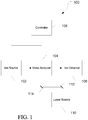
- mass spectrometry platform 100 can include components as displayed in the block diagram of Figure 1 . In various embodiments, elements of Figure 1 can be incorporated into mass spectrometry platform 100. According to various embodiments, mass spectrometer 100 can include an ion source 102, a mass analyzer 104, an ion detector 106, a controller 108, and a laser source 110.
- the ion source 102 generates a plurality of ions from a sample.
- the ion source can include, but is not limited to, a matrix assisted laser desorption/ionization (MALDI) source, electrospray ionization (ESI) source, atmospheric pressure chemical ionization (APCI) source, atmospheric pressure photoionization source (APPI), inductively coupled plasma (ICP) source, electron ionization source, chemical ionization source, photoionization source, glow discharge ionization source, thermospray ionization source, and the like.
- MALDI matrix assisted laser desorption/ionization
- ESI electrospray ionization
- APCI atmospheric pressure chemical ionization
- APPI atmospheric pressure photoionization source
- ICP inductively coupled plasma
- the mass analyzer 104 can separate ions based on a mass to charge ratio of the ions.
- the mass analyzer 104 can include a quadrupole mass filter analyzer, a quadrupole ion trap analyzer, a time-of-flight (TOF) analyzer, an electrostatic trap (e.g., ORBITRAP) mass analyzer, Fourier transform ion cyclotron resonance (FT-ICR) mass analyzer, and the like.
- the mass analyzer 104 can also be configured to fragment the ions using collision induced dissociation (CID) electron transfer dissociation (ETD), electron capture dissociation (ECD), photo induced dissociation (PID), ultraviolet photo dissociation (UVPD), surface induced dissociation (SID), and the like, and further separate the fragmented ions based on the mass-to-charge ratio.
- CID collision induced dissociation
- ETD electron transfer dissociation
- ECD electron capture dissociation
- PID photo induced dissociation
- UVPD ultraviolet photo dissociation
- SID surface induced dissociation
- the ion detector 106 can detect ions.
- the ion detector 106 can include an electron multiplier, a Faraday cup, an image charge detection scheme, and the like. Ions leaving the mass analyzer can be detected by the ion detector.
- the ion detector can be quantitative, such that an accurate count of the ions can be determined.
- the controller 108 can communicate with the ion source 102, the mass analyzer 104, and the ion detector 106.
- the controller 108 can configure the ion source or enable/disable the ion source.
- the controller 108 can configure the mass analyzer 104 to select a particular mass range to detect.
- the controller 108 can adjust the sensitivity of the ion detector 106, such as by adjusting the gain.
- the controller 108 can adjust the polarity of the ion detector 106 based on the polarity of the ions being detected.
- the ion detector 106 can be configured to detect positive ions or be configured to detected negative ions.
- the laser source 110 can generate a continuous or pulsed laser beam that can be directed to interact with ions with in the mass analyzer 104, such as ions trapped in an ion trap for photo induced dissociation. Alignment of the laser beam with the ion trapping space within the ion trap can be accomplished using various beam deflectors 112 and 114.
- Figure 2 is a diagram 200 illustrating alignment of a laser beam 202 to an ion cloud 204 in an ion trapping volume 206.
- Laser beam 202 can be directed to the ion trapping volume 206 using beam deflectors 208 and 210. Movement of one or more of beam deflectors 208 and 210 can alter the path of laser beam 202 from a misaligned path 212 to an aligned path 214. Misalignment of laser beam 202 can result in laser beam 202 missing a significant portion of ion cloud 204.
- a significant portion of the ions of the ion cloud 204 can interact with laser beam 202, which can result in excitation and possible fragmentation of the ions.
- beam deflectors 208 and 210 can be electronically controlled to manipulate the beam path, allowing electronic feedback that can be used to automate or even eliminate the alignment process.
- beam deflectors 208 and 210 can be mirror galvanometers, acousto-optic modulators (shown in FIG 3 .), or combination thereof.
- Mirror galvanometers can deflect the laser beam in response to an electric current.
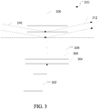
- FIG. 3 is a drawing illustrating the operation of an acousto-optic modulator.
- Acousto-optic modulators can use the acousto-optic effect to diffract the laser beam using sound waves (usually at radio-frequency).
- An RF modulator 302 drives a piezoelectric transducer 304 is attached to a material 306, such as glass.
- An RF signal can drive the transducer 304 to vibrate, creating sound waves in the material 306.
- Moving planes of expansion and compression 308 can change the index of refraction.
- Incoming photons 310 from the laser beam are refracted by the planes of expansion and compression 308 resulting in a deflected beam 312. Changing the frequency of the sound waves and thus the spacing between the planes of expansion and compression 308, changes the angle of deflection.
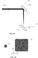
- Figure 4A illustrates an exemplary system 400 for scanning a laser beam 402 through an ion trapping volume 404.
- Beam deflectors 406 and 408 can be configured to oscillate in different directions relative to the beam axis Z.
- beam deflector 406 can be configured to sweep the laser beam 402 back and forth along the X direction as depicted in Fig 4B
- beam deflector 408 can be configured to sweep the laser beam 402 along the Y direction.
- an area larger than the beam width can be targeted, as illustrated in Figure 4B .
- Beam image 420 can represent the cross section of the laser beam 402, such as with stationary mirrors or at point 410 of Figure 4A
- beam image 422 can represent the cross section of laser beam 402 at point 412 of Figure 4A .
- Beam image 422 is significantly larger than beam image 420 due to scanning of the beam in the X and Y dimensions.
- the oscillation frequency of beam deflector 406 and the oscillation frequency of beam deflector 408 need to be different.
- the beam image would correspond to a diagonal line.
- the oscillation frequency of beam deflector 408 can be larger than the oscillation frequency of beam deflector 406, such as a multiple of the oscillation frequency of beam deflector 406.
- the oscillation frequency of beam deflector 408 can be an integer multiple of the oscillation frequency of beam deflector 406.
- the oscillation frequency of beam deflector 408 is eight times greater than the oscillation frequency of beam deflector 406, the beam will cross the Y dimension eight times for each pass along the X dimension. This can enable a sweep area that is up to about eight times larger than the beam width along the X dimension.
- the oscillation frequency of beam deflector 408 can be not less than the oscillation frequency of beam deflector 406 times the ratio of the X dimension to the beam width, or more generally, the higher oscillation frequency can be not less than the lower oscillation frequency times the ratio of the first dimension to the beam width .
- the laser beam 402 can be a pulsed laser with a pulse frequency that is higher than the higher of the oscillation frequencies of beam deflector 406 and 408.
- the oscillation frequency of beam deflector 408 eight times greater than the oscillation frequency of beam deflector 406, if the pulse frequency of the laser is 8 times higher than the oscillation frequency of beam deflector 408, then there will be 8 pulses per pass of the Y dimension. This can enable a sweep area that is up to about eight times larger than the beam width along the Y dimension.
- the pulse frequency of laser beam 402 can be not less than the oscillation frequency of beam deflector 408 times the ratio of the Y dimension to the beam width, or more generally,the pulse frequency can be not less than the higher oscillation frequency times the ratio of the second dimension to the beam width.
- the beam deflector 406 can have a larger oscillation frequency than beam deflector 408 to achieve similar results, and the pulse frequency can be higher than the oscillation frequency of beam deflector 406.
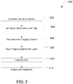
- FIG. 5 is a flow diagram illustrating an exemplary method 500 of scanning a laser through an ion trapping volume to excite ions within the ion trapping volume which can lead to fragmentation of the ions.
- ions can be produced at an ion source, such as ion source 102 of Figure 1 .
- the ions can be produced by ionizing a sample, such that compounds in the sample can produce ions representative of the sample compounds.
- ions can be guided from the ion source to an ion trap using ion optics, and at 506, the ions can be trapped by the ion trap in an ion trapping volume.
- an area of the trapping volume can be swept with a laser.
- First and second beam deflectors can cause oscillation of the laser with the first beam deflector causing oscillation in a first direction orthogonal to the beam axis and the second beam deflector causing oscillation in a second direction orthogonal to the beam axis and different from the first direction, such as orthogonal to the first direction.
- the oscillation in the first direction can be at a first frequency and the oscillation in the second direction can be at a second frequency different than the first frequency.
- the second frequency can be a multiple, such as an integer multiple, of the first frequency. Additionally, the second frequency can be not less than the first frequency times the ratio of the first dimension to a beam width.
- the laser can be a pulsed laser with a pulse frequency higher than the second frequency, such as not less than the second frequency times the ratio of the second dimension to a beam width.
- the laser can interact with the ions in the trapping volume causing at least a portion of them to fragment thereby producing fragment ions within the trapping volume.
- the mass-to-charge ratios of the fragment ions can be determined. In various embodiments, the mass-to-charge ratio of the fragment ions can be used to identify and/or quantify the compounds in the sample.
- the laser may be stepped point-by-point through the swept area while the mass spectrometer monitors spectra for laser-induced signal. When a maximum in this signal is found, the beam deflector parameters can be recorded so that the beam deflectors can be returned to the state which resulted in the maximum.
- Figure 6 illustrates an exemplary mass spectrometry system 600 with multiple trapping volumes 602, 604, and 606.
- trapping volume 602 can trap ion cloud 608
- trapping volume 604 can trap ion cloud 610
- trapping volume 606 can trap ion cloud 612.
- An ion cloud may only be present in one of trapping volumes 602, 604, 606, rather than having ion clouds simultaneously in multiple trapping volumes.
- Beam deflectors 614 and 616 can be controlled to direct the laser 618 to a particular one of trapping volumes 602, 604, and 606.
- laser 618 can be directed along path 620 to focus on ion cloud 608 in ion trap 602, while in another configuration, laser 618 can be directed along path 622 to focus on ion cloud 610 in ion trap 604.
- the laser can be realigned to a different trapping volume during or between experiments without having to manually adjust a series of fixed beam deflectors.
- laser 618 can be independently aligned to each of the ion trapping volumes during an alignment process and the beam deflector parameters can be recorded for each ion trapping volume. Selecting an ion trapping volume can be accomplished by returning the deflectors to the stored configuration for the specified trapping volume.
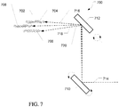
- FIG. 7 illustrates an exemplary mass spectrometry system 700 with ion trap 702.
- ion trap 702 can trap ion cloud 704, 706, and 708.
- Beam deflectors 710 and 712 can be controlled to direct the laser 714 to a particular one of ion clouds 704, 706, and 708.
- laser 714 can be directed along path 716 to focus on ion cloud 704, while in another configuration, laser 714 can be directed along path 718 to focus on ion cloud 706 in ion trap 704.
- laser 714 can be directed along path 720 to focus on ion cloud 708.
- FIG. 8 is a flow diagram illustrating a method 800 of selectively targeting ion clouds.
- alignments can be obtained for each ion cloud.
- the ion clouds may be in different nominally aligned trapping volumes or in different regions of a trapping volume or ion trap.
- the laser can be scanned through the trapping volume while an ion cloud is present and a laser-induced signal can be monitored to identify the beam deflector parameters that maximize the laser-induced signal.
- the process can be repeated for each ion cloud of interest.
- the beam deflector parameters can be stored for each ion cloud location and retrieved as needed.
- a calibrant ion or alignment standard can be present in the trapping volume during the alignment to generally align the laser to a trapping volume, or an ion of interest can be used to more specifically align the laser to the location of those ions within the trap.
- an ion cloud location can be selected for targeting, and at 806, the beam deflector configuration can be changed to match the beam deflector parameters identified to align the laser with the selected ion cloud location.
- the laser can irradiate the ion cloud causing the ions to fragment, and at 810, the ion fragments can be analyzed.
- the specification may have presented a method and/or process as a particular sequence of steps.
- the method or process should not be limited to the particular sequence of steps described.
- other sequences of steps may be possible. Therefore, the particular order of the steps set forth in the specification should not be construed as limitations on the claims.
- the claims directed to the method and/or process should not be limited to the performance of their steps in the order written, and one skilled in the art can readily appreciate that the sequences may be varied and still remain within the spirit and scope of the various embodiments.
Landscapes
- Chemical & Material Sciences (AREA)
- Analytical Chemistry (AREA)
- Chemical Kinetics & Catalysis (AREA)
- Other Investigation Or Analysis Of Materials By Electrical Means (AREA)
- Electron Tubes For Measurement (AREA)
Abstract
Description
- The present disclosure generally relates to the field of mass spectrometry including coupling a laser beam to a mass spectrometer.
- Mass spectrometry is an analytical chemistry technique that can identify the amount and type of chemicals present in a sample by measuring the mass-to-charge ratio and abundance of gas-phase ions. Laser light can be used to induce fragmentation of the gas-phase ions to provide additional information about the ions, such as structural information.
- When laser light is used for mass spectrometry experiments, alignment of the laser beam with both the ionizing chamber and critically with the ion cloud can be a significant and recurring problem. Static optical mounting hardware is often used, and the beam is aligned at instrument installation. Inevitably, thermal cycling, mechanical vibrations, or other disturbances lead to beam misalignment, which must then be corrected in the field, resulting in costs and lost time. Additionally, experience shows that adequate alignment is difficult even for personnel trained in both optical hardware and mass spectrometry, and sometimes even requires the "magic" of a seasoned expert.
- As such, there is a need for new systems and methods for coupling a laser beam to a mass spectrometer.
- In a first aspect, a mass spectrometry system can include a laser source, a trapping volume, first and second beam deflectors, and a deflector controller. The first and second beam deflectors can be arranged on a path from the laser source to the trapping volume. The first beam deflector can be configured to oscillate in a first direction at a first frequency and the second beam deflector can be configured to oscillate in a second direction orthogonal to the first direction at a second frequency. The deflector controller can be configured to scan a scanned area within the trapping volume with the laser by controlling the oscillation of the first and second beam deflectors, causing ions trapped within the trapping volume to become excited. The excited ions can fragment into fragment ions. The scanned area can have a first dimension defined by the oscillation in first direction and a second dimension defined by the oscillation in the second direction.
- In various embodiments of the first aspect, the first and second beam deflectors can be mirror galvanometers.
- In various embodiments of the first aspect, the first and second beam deflectors can be acousto-optic modulators.
- In various embodiments of the first aspect, the second frequency can be a multiple of the first frequency. In particular embodiments, the multiple can be an integer multiple. In particular embodiments, the second frequency can be not less than the first frequency times the ratio of the first dimension to a beam width.
- In various embodiments of the first aspect, the laser source can be a pulsed laser source with a pulse frequency higher than the second frequency. In particular embodiments, the pulse frequency can be not less than the second frequency times the ratio of the second dimension to a beam width.
- In various embodiments of the first aspect, the mass spectrometry system can further include an ion source for producing the ions and ion optics for moving the ions from the ion source to the trapping volume.
- In various embodiments of the first aspect, the mass spectrometry system can further include a mass analyzer configured to determine the mass to charge ratio of the ions in the trapping volume.
- In a second aspect, a method of analyzing ions can include trapping ions within a trapping volume, sweeping an area of the trapping volume with a laser by oscillating first and second beam deflectors to excite the trapped ions, fragmenting the excited ions within the trapping volume to produce ion fragments, and determining a mass-to-charge ratio for the ion fragments. The first beam deflector can be configured to oscillate in a first direction at a first frequency and the second beam deflector can be configured to oscillate in a second direction orthogonal to the first direction at a second frequency;
- In various embodiments of the second aspect, the first and second beam deflectors can be mirror galvanometers.
- In various embodiments of the second aspect, the first and second beam deflectors can be acousto-optic modulators.
- In various embodiments of the second aspect, the second frequency can be a multiple of the first frequency. In particular embodiments, the multiple can be an integer multiple. In particular embodiments, the second frequency can be not less than the first frequency times the ratio of the first dimension to a beam width.
- In various embodiments of the second aspect, the laser can be a pulsed laser with a pulse frequency higher than the second frequency. In particular embodiments, the pulse frequency can be not less than the second frequency times the ratio of the second dimension to a beam width.
- In various embodiments of the second aspect, the method can further include producing ions from a sample in an ion source, and guiding the ions from the ion source to the trapping volume using ion optics.
- For a more complete understanding of the principles disclosed herein, and the advantages thereof, reference is now made to the following descriptions taken in conjunction with the accompanying drawings and exhibits, in which:
-
Figure 1 is a block diagram of an exemplary mass spectrometry system, in accordance with various embodiments. -
Figure 2 is a diagram illustrating alignment of a laser to an ion cloud in an ion trapping volume within an exemplary mass spectrometer, in accordance with various embodiments. -
Figure 3 is a drawing illustrating an alternate laser deflector for use in an exemplary mass spectrometer, in accordance with various embodiments. -
Figure 4A and 4B illustrate scanning a laser though an ion trapping volume within an exemplary mass spectrometer, in accordance with various embodiments. -
Figures 5 is a flow diagram illustrating an exemplary method of scanning a laser through an ion trapping volume, in accordance with various embodiments. -
Figure 6 is a drawing illustrating altering the laser alignment to target other ion clouds trapped within various trapping volumes of an exemplary mass spectrometer, in accordance with various embodiments. -
Figure 7 is a drawing illustrating altering the laser alignment to target other ion clouds trapped within a single trapping volume of an exemplary mass spectrometer, in accordance with various embodiments. -
Figures 8 is a flow diagram illustrating an exemplary method of selectively targeting one of a plurality of ion clouds within an exemplary mass spectrometer, in accordance with various embodiments. - It is to be understood that the figures are not necessarily drawn to scale, nor are the objects in the figures necessarily drawn to scale in relationship to one another. The figures are depictions that are intended to bring clarity and understanding to various embodiments of apparatuses, systems, and methods disclosed herein. Wherever possible, the same reference numbers will be used throughout the drawings to refer to the same or like parts. Moreover, it should be appreciated that the drawings are not intended to limit the scope of the present teachings in any way.
- Embodiments of systems and methods for ion analysis are described herein and in the accompanying exhibits.
- The section headings used herein are for organizational purposes only and are not to be construed as limiting the described subject matter in any way.
- In this detailed description of the various embodiments, for purposes of explanation, numerous specific details are set forth to provide a thorough understanding of the embodiments disclosed. One skilled in the art will appreciate, however, that these various embodiments may be practiced with or without these specific details. In other instances, structures and devices are shown in block diagram form. Furthermore, one skilled in the art can readily appreciate that the specific sequences in which methods are presented and performed are illustrative and it is contemplated that the sequences can be varied and still remain within the spirit and scope of the various embodiments disclosed herein.
- All literature and similar materials cited in this application, including but not limited to, patents, patent applications, articles, books, treatises, and internet web pages are expressly incorporated by reference in their entirety for any purpose. Unless described otherwise, all technical and scientific terms used herein have a meaning as is commonly understood by one of ordinary skill in the art to which the various embodiments described herein belongs.
- It will be appreciated that there is an implied "about" prior to the temperatures, concentrations, times, pressures, flow rates, cross-sectional areas, etc. discussed in the present teachings, such that slight and insubstantial deviations are within the scope of the present teachings. In this application, the use of the singular includes the plural unless specifically stated otherwise. Also, the use of "comprise", "comprises", "comprising", "contain", "contains", "containing", "include", "includes", and "including" are not intended to be limiting. It is to be understood that both the foregoing general description and the following detailed description are exemplary and explanatory only and are not restrictive of the present teachings.
- As used herein, "a" or "an" also may refer to "at least one" or "one or more." Also, the use of "or" is inclusive, such that the phrase "A or B" is true when "A" is true, "B" is true, or both "A" and "B" are true. Further, unless otherwise required by context, singular terms shall include pluralities and plural terms shall include the singular.
- A "system" sets forth a set of components, real or abstract, comprising a whole where each component interacts with or is related to at least one other component within the whole.
- Various embodiments of
mass spectrometry platform 100 can include components as displayed in the block diagram ofFigure 1 . In various embodiments, elements ofFigure 1 can be incorporated intomass spectrometry platform 100. According to various embodiments,mass spectrometer 100 can include anion source 102, amass analyzer 104, anion detector 106, acontroller 108, and alaser source 110. - In various embodiments, the
ion source 102 generates a plurality of ions from a sample. The ion source can include, but is not limited to, a matrix assisted laser desorption/ionization (MALDI) source, electrospray ionization (ESI) source, atmospheric pressure chemical ionization (APCI) source, atmospheric pressure photoionization source (APPI), inductively coupled plasma (ICP) source, electron ionization source, chemical ionization source, photoionization source, glow discharge ionization source, thermospray ionization source, and the like. - In various embodiments, the
mass analyzer 104 can separate ions based on a mass to charge ratio of the ions. For example, themass analyzer 104 can include a quadrupole mass filter analyzer, a quadrupole ion trap analyzer, a time-of-flight (TOF) analyzer, an electrostatic trap (e.g., ORBITRAP) mass analyzer, Fourier transform ion cyclotron resonance (FT-ICR) mass analyzer, and the like. In various embodiments, themass analyzer 104 can also be configured to fragment the ions using collision induced dissociation (CID) electron transfer dissociation (ETD), electron capture dissociation (ECD), photo induced dissociation (PID), ultraviolet photo dissociation (UVPD), surface induced dissociation (SID), and the like, and further separate the fragmented ions based on the mass-to-charge ratio. - In various embodiments, the
ion detector 106 can detect ions. For example, theion detector 106 can include an electron multiplier, a Faraday cup, an image charge detection scheme, and the like. Ions leaving the mass analyzer can be detected by the ion detector. In various embodiments, the ion detector can be quantitative, such that an accurate count of the ions can be determined. - In various embodiments, the
controller 108 can communicate with theion source 102, themass analyzer 104, and theion detector 106. For example, thecontroller 108 can configure the ion source or enable/disable the ion source. Additionally, thecontroller 108 can configure themass analyzer 104 to select a particular mass range to detect. Further, thecontroller 108 can adjust the sensitivity of theion detector 106, such as by adjusting the gain. Additionally, thecontroller 108 can adjust the polarity of theion detector 106 based on the polarity of the ions being detected. For example, theion detector 106 can be configured to detect positive ions or be configured to detected negative ions. - In various embodiments, the
laser source 110 can generate a continuous or pulsed laser beam that can be directed to interact with ions with in themass analyzer 104, such as ions trapped in an ion trap for photo induced dissociation. Alignment of the laser beam with the ion trapping space within the ion trap can be accomplished usingvarious beam deflectors -
Figure 2 is a diagram 200 illustrating alignment of alaser beam 202 to anion cloud 204 in anion trapping volume 206.Laser beam 202 can be directed to theion trapping volume 206 usingbeam deflectors beam deflectors laser beam 202 from amisaligned path 212 to an alignedpath 214. Misalignment oflaser beam 202 can result inlaser beam 202 missing a significant portion ofion cloud 204. Alternatively, with the alignedpath 214, a significant portion of the ions of theion cloud 204 can interact withlaser beam 202, which can result in excitation and possible fragmentation of the ions. - In various embodiments,
beam deflectors beam deflectors FIG 3 .), or combination thereof. Mirror galvanometers can deflect the laser beam in response to an electric current. -
Figure 3 is a drawing illustrating the operation of an acousto-optic modulator. Acousto-optic modulators can use the acousto-optic effect to diffract the laser beam using sound waves (usually at radio-frequency). AnRF modulator 302 drives apiezoelectric transducer 304 is attached to amaterial 306, such as glass. An RF signal can drive thetransducer 304 to vibrate, creating sound waves in thematerial 306. Moving planes of expansion andcompression 308 can change the index of refraction.Incoming photons 310 from the laser beam are refracted by the planes of expansion andcompression 308 resulting in a deflectedbeam 312. Changing the frequency of the sound waves and thus the spacing between the planes of expansion andcompression 308, changes the angle of deflection. -
Figure 4A illustrates anexemplary system 400 for scanning alaser beam 402 through anion trapping volume 404. Beam deflectors 406 and 408 can be configured to oscillate in different directions relative to the beam axis Z. For example,beam deflector 406 can be configured to sweep thelaser beam 402 back and forth along the X direction as depicted inFig 4B , andbeam deflector 408 can be configured to sweep thelaser beam 402 along the Y direction. By appropriately setting the oscillation frequency forbeam deflectors Figure 4B .Beam image 420 can represent the cross section of thelaser beam 402, such as with stationary mirrors or atpoint 410 ofFigure 4A , andbeam image 422 can represent the cross section oflaser beam 402 atpoint 412 ofFigure 4A .Beam image 422 is significantly larger thanbeam image 420 due to scanning of the beam in the X and Y dimensions. - In various embodiments, to effectively scan the target area, the oscillation frequency of
beam deflector 406 and the oscillation frequency ofbeam deflector 408 need to be different. When the oscillation frequencies are the same, the beam image would correspond to a diagonal line. In various embodiments, the oscillation frequency ofbeam deflector 408 can be larger than the oscillation frequency ofbeam deflector 406, such as a multiple of the oscillation frequency ofbeam deflector 406. In particular embodiments, the oscillation frequency ofbeam deflector 408 can be an integer multiple of the oscillation frequency ofbeam deflector 406. By way of example, if the oscillation frequency ofbeam deflector 408 is eight times greater than the oscillation frequency ofbeam deflector 406, the beam will cross the Y dimension eight times for each pass along the X dimension. This can enable a sweep area that is up to about eight times larger than the beam width along the X dimension. In particular embodiments, the oscillation frequency ofbeam deflector 408 can be not less than the oscillation frequency ofbeam deflector 406 times the ratio of the X dimension to the beam width, or more generally, the higher oscillation frequency can be not less than the lower oscillation frequency times the ratio of the first dimension to the beam width . - In various embodiments, the
laser beam 402 can be a pulsed laser with a pulse frequency that is higher than the higher of the oscillation frequencies ofbeam deflector beam deflector 408 eight times greater than the oscillation frequency ofbeam deflector 406, if the pulse frequency of the laser is 8 times higher than the oscillation frequency ofbeam deflector 408, then there will be 8 pulses per pass of the Y dimension. This can enable a sweep area that is up to about eight times larger than the beam width along the Y dimension. The pulse frequency oflaser beam 402 can be not less than the oscillation frequency ofbeam deflector 408 times the ratio of the Y dimension to the beam width, or more generally,the pulse frequency can be not less than the higher oscillation frequency times the ratio of the second dimension to the beam width. - In alternate embodiments, the
beam deflector 406 can have a larger oscillation frequency thanbeam deflector 408 to achieve similar results, and the pulse frequency can be higher than the oscillation frequency ofbeam deflector 406. -
Figures 5 is a flow diagram illustrating anexemplary method 500 of scanning a laser through an ion trapping volume to excite ions within the ion trapping volume which can lead to fragmentation of the ions. At 502, ions can be produced at an ion source, such asion source 102 ofFigure 1 . In various embodiments, the ions can be produced by ionizing a sample, such that compounds in the sample can produce ions representative of the sample compounds. At 504, ions can be guided from the ion source to an ion trap using ion optics, and at 506, the ions can be trapped by the ion trap in an ion trapping volume. - At 508, an area of the trapping volume can be swept with a laser. First and second beam deflectors can cause oscillation of the laser with the first beam deflector causing oscillation in a first direction orthogonal to the beam axis and the second beam deflector causing oscillation in a second direction orthogonal to the beam axis and different from the first direction, such as orthogonal to the first direction. The oscillation in the first direction can be at a first frequency and the oscillation in the second direction can be at a second frequency different than the first frequency.
- In various embodiments, the second frequency can be a multiple, such as an integer multiple, of the first frequency. Additionally, the second frequency can be not less than the first frequency times the ratio of the first dimension to a beam width.
- In various embodiments, the laser can be a pulsed laser with a pulse frequency higher than the second frequency, such as not less than the second frequency times the ratio of the second dimension to a beam width.
- At 510, the laser can interact with the ions in the trapping volume causing at least a portion of them to fragment thereby producing fragment ions within the trapping volume. At 512, the mass-to-charge ratios of the fragment ions can be determined. In various embodiments, the mass-to-charge ratio of the fragment ions can be used to identify and/or quantify the compounds in the sample.
- In other embodiments, it may be desirable to align the laser to achieve maximum laser-induced signal rather than scanning the ion volume. The laser can be stepped point-by-point through the swept area while the mass spectrometer monitors spectra for laser-induced signal. When a maximum in this signal is found, the beam deflector parameters can be recorded so that the beam deflectors can be returned to the state which resulted in the maximum.
-
Figure 6 illustrates an exemplarymass spectrometry system 600 with multiple trappingvolumes volume 602 can trapion cloud 608, trappingvolume 604 can trapion cloud 610, and trappingvolume 606 can trapion cloud 612. An ion cloud may only be present in one of trappingvolumes laser 618 to a particular one of trappingvolumes beam deflectors laser 618 can be directed alongpath 620 to focus onion cloud 608 inion trap 602, while in another configuration,laser 618 can be directed alongpath 622 to focus onion cloud 610 inion trap 604. Using electronically controlled beam deflectors, the laser can be realigned to a different trapping volume during or between experiments without having to manually adjust a series of fixed beam deflectors. - In various embodiments,
laser 618 can be independently aligned to each of the ion trapping volumes during an alignment process and the beam deflector parameters can be recorded for each ion trapping volume. Selecting an ion trapping volume can be accomplished by returning the deflectors to the stored configuration for the specified trapping volume. -
Figure 7 illustrates an exemplarymass spectrometry system 700 withion trap 702. At various times,ion trap 702 can trapion cloud laser 714 to a particular one ofion clouds beam deflectors laser 714 can be directed alongpath 716 to focus onion cloud 704, while in another configuration,laser 714 can be directed alongpath 718 to focus onion cloud 706 inion trap 704. Similarly, ion a third configuration,laser 714 can be directed alongpath 720 to focus onion cloud 708. -
Figures 8 is a flow diagram illustrating amethod 800 of selectively targeting ion clouds. At 802, alignments can be obtained for each ion cloud. The ion clouds may be in different nominally aligned trapping volumes or in different regions of a trapping volume or ion trap. For example, the laser can be scanned through the trapping volume while an ion cloud is present and a laser-induced signal can be monitored to identify the beam deflector parameters that maximize the laser-induced signal. The process can be repeated for each ion cloud of interest. The beam deflector parameters can be stored for each ion cloud location and retrieved as needed. In various embodiments, a calibrant ion or alignment standard can be present in the trapping volume during the alignment to generally align the laser to a trapping volume, or an ion of interest can be used to more specifically align the laser to the location of those ions within the trap. - At 804, an ion cloud location can be selected for targeting, and at 806, the beam deflector configuration can be changed to match the beam deflector parameters identified to align the laser with the selected ion cloud location.
- At 808, the laser can irradiate the ion cloud causing the ions to fragment, and at 810, the ion fragments can be analyzed.
- While the present teachings are described in conjunction with various embodiments, it is not intended that the present teachings be limited to such embodiments. On the contrary, the present teachings encompass various alternatives, modifications, and equivalents, as will be appreciated by those of skill in the art.
- Further, in describing various embodiments, the specification may have presented a method and/or process as a particular sequence of steps. However, to the extent that the method or process does not rely on the particular order of steps set forth herein, the method or process should not be limited to the particular sequence of steps described. As one of ordinary skill in the art would appreciate, other sequences of steps may be possible. Therefore, the particular order of the steps set forth in the specification should not be construed as limitations on the claims. In addition, the claims directed to the method and/or process should not be limited to the performance of their steps in the order written, and one skilled in the art can readily appreciate that the sequences may be varied and still remain within the spirit and scope of the various embodiments.
Claims (15)
- A mass spectrometry system comprising:a laser source;a trapping volume;first and second beam deflectors arranged on a path from the laser source to the trapping volume, the first beam deflector configured to oscillate in a first direction at a first frequency and the second beam deflector configured to oscillate in a second direction orthogonal to the first direction at a second frequency;a deflector controller configured to:scan a scanned area within the trapping volume with the laser by controlling the oscillation of the first and second beam deflectors to cause ions trapped within the trapping volume to become excited, the scanned area having a first dimension defined by the oscillation in first direction and a second dimension defined by the oscillation in the second direction.
- The mass spectrometry system of claim 1 wherein the first and second beam deflectors are mirror galvanometers.
- The mass spectrometry system of claim 1 wherein the first and second beam deflectors are acousto-optic modulators.
- The mass spectrometry system of claim 1 wherein the second frequency is a multiple of the first frequency, such as the second frequency is an integer multiple of the first frequency.
- The mass spectrometry system of claim 1 wherein the second frequency is not less than the first frequency times the ratio of the first dimension to a beam width.
- The mass spectrometry system of claim 1 wherein the laser source is a pulsed laser source with a pulse frequency higher than the second frequency, such as the pulse frequency is not less than the second frequency times the ratio of the second dimension to a beam width.
- The mass spectrometry system of claim 1 further comprising an ion source for producing the ions, and ion optics for moving the ions from the ion source to the trapping volume.
- The mass spectrometry system of claim 1 further comprising a mass analyzer configured to determine the mass to charge ratio of the ions.
- A method of analyzing ion fragments, comprising:trapping ions within a trapping volume;sweeping an area of the trapping volume with a laser by oscillating first and second beam deflectors to excite the ions, the first beam deflector configured to oscillate in a first direction at a first frequency and the second beam deflector configured to oscillate in a second direction orthogonal to the first direction at a second frequency;fragmenting the excited ions within the trapping volume to produce ion fragments;determining a mass-to-charge ratio for the ion fragments.
- The method of claim 9 wherein the first and second beam deflectors are mirror galvanometers.
- The method of claim 9 wherein the first and second beam deflectors are acousto-optic modulators.
- The method of claim 9 wherein the second frequency is a multiple of the first frequency, such as the second frequency is an integer multiple of the first frequency
- The method of claim 9 wherein the second frequency is not less than the first frequency times the ratio of the first dimension to a beam width.
- The method of claim 9 wherein the laser is a pulsed laser with a pulse frequency higher than the second frequency, such as the pulse frequency is not less than the second frequency times the ratio of the second dimension to a beam width.
- The method of claim 9 further comprising producing ions from a sample in an ion source, and guiding the ions from the ion source to the trapping volume using ion optics.
Applications Claiming Priority (1)
| Application Number | Priority Date | Filing Date | Title |
|---|---|---|---|
| US15/389,377 US9892903B1 (en) | 2016-12-22 | 2016-12-22 | Systems and methods for coupling a laser beam to a mass spectrometer |
Publications (2)
| Publication Number | Publication Date |
|---|---|
| EP3340277A1 true EP3340277A1 (en) | 2018-06-27 |
| EP3340277B1 EP3340277B1 (en) | 2019-09-04 |
Family
ID=60673863
Family Applications (1)
| Application Number | Title | Priority Date | Filing Date |
|---|---|---|---|
| EP17208213.3A Active EP3340277B1 (en) | 2016-12-22 | 2017-12-18 | Systems and methods for coupling a laser beam to a mass spectrometer |
Country Status (3)
| Country | Link |
|---|---|
| US (1) | US9892903B1 (en) |
| EP (1) | EP3340277B1 (en) |
| CN (1) | CN108231530B (en) |
Cited By (1)
| Publication number | Priority date | Publication date | Assignee | Title |
|---|---|---|---|---|
| CN112843497A (en) * | 2021-01-05 | 2021-05-28 | 中国科学院上海高等研究院 | Proton beam scanning device and scanning method based on radio frequency deflection cavity technology |
Families Citing this family (1)
| Publication number | Priority date | Publication date | Assignee | Title |
|---|---|---|---|---|
| US11906449B2 (en) * | 2021-01-28 | 2024-02-20 | Shimadzu Corporation | Mass spectrometer |
Citations (4)
| Publication number | Priority date | Publication date | Assignee | Title |
|---|---|---|---|---|
| US20050157763A1 (en) * | 2004-01-20 | 2005-07-21 | Symbol Technologies, Inc. | Electronic alignment of acousto-optic modulator for modulating a laser |
| US20090242753A1 (en) * | 2004-12-16 | 2009-10-01 | Universite Claude Bernard Lyon 1 | Device and mass analysis of molecules using uv or visible laser beam photodissociation |
| US20100207023A1 (en) * | 2009-02-13 | 2010-08-19 | Dh Technologies Development Pte. Ltd. | Apparatus and method of photo fragmentation |
| US20130056628A1 (en) * | 2011-09-06 | 2013-03-07 | Armin Holle | Laser spot control in maldi mass spectrometers |
Family Cites Families (2)
| Publication number | Priority date | Publication date | Assignee | Title |
|---|---|---|---|---|
| CN100541270C (en) * | 2004-01-20 | 2009-09-16 | 讯宝科技公司 | Electrical tuning of an acousto-optic modulator for modulating laser light |
| CN103018318B (en) * | 2012-12-21 | 2015-03-18 | 中国科学院地质与地球物理研究所 | Measuring method for distribution coefficient of zircon microelement and zircon magma microelement |
-
2016
- 2016-12-22 US US15/389,377 patent/US9892903B1/en not_active Expired - Fee Related
-
2017
- 2017-12-18 EP EP17208213.3A patent/EP3340277B1/en active Active
- 2017-12-21 CN CN201711393598.5A patent/CN108231530B/en active Active
Patent Citations (4)
| Publication number | Priority date | Publication date | Assignee | Title |
|---|---|---|---|---|
| US20050157763A1 (en) * | 2004-01-20 | 2005-07-21 | Symbol Technologies, Inc. | Electronic alignment of acousto-optic modulator for modulating a laser |
| US20090242753A1 (en) * | 2004-12-16 | 2009-10-01 | Universite Claude Bernard Lyon 1 | Device and mass analysis of molecules using uv or visible laser beam photodissociation |
| US20100207023A1 (en) * | 2009-02-13 | 2010-08-19 | Dh Technologies Development Pte. Ltd. | Apparatus and method of photo fragmentation |
| US20130056628A1 (en) * | 2011-09-06 | 2013-03-07 | Armin Holle | Laser spot control in maldi mass spectrometers |
Cited By (1)
| Publication number | Priority date | Publication date | Assignee | Title |
|---|---|---|---|---|
| CN112843497A (en) * | 2021-01-05 | 2021-05-28 | 中国科学院上海高等研究院 | Proton beam scanning device and scanning method based on radio frequency deflection cavity technology |
Also Published As
| Publication number | Publication date |
|---|---|
| US9892903B1 (en) | 2018-02-13 |
| CN108231530A (en) | 2018-06-29 |
| CN108231530B (en) | 2019-08-02 |
| EP3340277B1 (en) | 2019-09-04 |
Similar Documents
| Publication | Publication Date | Title |
|---|---|---|
| US10593533B2 (en) | Imaging mass spectrometer | |
| CA2373351C (en) | Ion mobility and mass spectrometer | |
| JP6091504B2 (en) | MALDI imaging and ion source | |
| EP1926123B1 (en) | Mass spectrometer and method of mass spectrometry | |
| JP5027507B2 (en) | Method and apparatus for providing a two-dimensional substantially quadrupole electric field having selected hexapole components | |
| EP3510627B1 (en) | Quadrupole devices | |
| EP2360711A2 (en) | Ion source and methods for maldi mass spectrometry | |
| CN108292586A (en) | It is imaged mass spectrograph | |
| WO2018138485A1 (en) | Ion detector assembly | |
| CN107690690B (en) | Mass analysis method using ion filtration | |
| CN112740357B (en) | Precursor accumulation in single charge state in mass spectrometry | |
| EP1305819A4 (en) | INSTRUMENT FOR SEPARATING IONS | |
| JP7268178B2 (en) | quadrupole device | |
| EP3510628B1 (en) | Quadrupole devices | |
| US6884996B2 (en) | Space charge adjustment of activation frequency | |
| EP3340277B1 (en) | Systems and methods for coupling a laser beam to a mass spectrometer | |
| US20050242280A1 (en) | Ion cyclotron resonance mass spectrometer | |
| CN112602166B (en) | A top-down proteomics approach using EXD and PTR | |
| JP6022383B2 (en) | Mass spectrometry system and method | |
| WO2022195536A1 (en) | System and method for variable fft analysis windows in mass spectrometry | |
| IL146238A (en) | Ion mobility and mass spectrometer |
Legal Events
| Date | Code | Title | Description |
|---|---|---|---|
| PUAI | Public reference made under article 153(3) epc to a published international application that has entered the european phase |
Free format text: ORIGINAL CODE: 0009012 |
|
| STAA | Information on the status of an ep patent application or granted ep patent |
Free format text: STATUS: THE APPLICATION HAS BEEN PUBLISHED |
|
| AK | Designated contracting states |
Kind code of ref document: A1 Designated state(s): AL AT BE BG CH CY CZ DE DK EE ES FI FR GB GR HR HU IE IS IT LI LT LU LV MC MK MT NL NO PL PT RO RS SE SI SK SM TR |
|
| AX | Request for extension of the european patent |
Extension state: BA ME |
|
| STAA | Information on the status of an ep patent application or granted ep patent |
Free format text: STATUS: REQUEST FOR EXAMINATION WAS MADE |
|
| 17P | Request for examination filed |
Effective date: 20190102 |
|
| RBV | Designated contracting states (corrected) |
Designated state(s): AL AT BE BG CH CY CZ DE DK EE ES FI FR GB GR HR HU IE IS IT LI LT LU LV MC MK MT NL NO PL PT RO RS SE SI SK SM TR |
|
| GRAP | Despatch of communication of intention to grant a patent |
Free format text: ORIGINAL CODE: EPIDOSNIGR1 |
|
| STAA | Information on the status of an ep patent application or granted ep patent |
Free format text: STATUS: GRANT OF PATENT IS INTENDED |
|
| INTG | Intention to grant announced |
Effective date: 20190329 |
|
| GRAS | Grant fee paid |
Free format text: ORIGINAL CODE: EPIDOSNIGR3 |
|
| GRAA | (expected) grant |
Free format text: ORIGINAL CODE: 0009210 |
|
| STAA | Information on the status of an ep patent application or granted ep patent |
Free format text: STATUS: THE PATENT HAS BEEN GRANTED |
|
| AK | Designated contracting states |
Kind code of ref document: B1 Designated state(s): AL AT BE BG CH CY CZ DE DK EE ES FI FR GB GR HR HU IE IS IT LI LT LU LV MC MK MT NL NO PL PT RO RS SE SI SK SM TR |
|
| REG | Reference to a national code |
Ref country code: GB Ref legal event code: FG4D |
|
| REG | Reference to a national code |
Ref country code: CH Ref legal event code: EP |
|
| REG | Reference to a national code |
Ref country code: AT Ref legal event code: REF Ref document number: 1176559 Country of ref document: AT Kind code of ref document: T Effective date: 20190915 |
|
| REG | Reference to a national code |
Ref country code: DE Ref legal event code: R096 Ref document number: 602017006763 Country of ref document: DE Ref country code: IE Ref legal event code: FG4D |
|
| REG | Reference to a national code |
Ref country code: NL Ref legal event code: MP Effective date: 20190904 |
|
| REG | Reference to a national code |
Ref country code: LT Ref legal event code: MG4D |
|
| PG25 | Lapsed in a contracting state [announced via postgrant information from national office to epo] |
Ref country code: NO Free format text: LAPSE BECAUSE OF FAILURE TO SUBMIT A TRANSLATION OF THE DESCRIPTION OR TO PAY THE FEE WITHIN THE PRESCRIBED TIME-LIMIT Effective date: 20191204 Ref country code: LT Free format text: LAPSE BECAUSE OF FAILURE TO SUBMIT A TRANSLATION OF THE DESCRIPTION OR TO PAY THE FEE WITHIN THE PRESCRIBED TIME-LIMIT Effective date: 20190904 Ref country code: BG Free format text: LAPSE BECAUSE OF FAILURE TO SUBMIT A TRANSLATION OF THE DESCRIPTION OR TO PAY THE FEE WITHIN THE PRESCRIBED TIME-LIMIT Effective date: 20191204 Ref country code: FI Free format text: LAPSE BECAUSE OF FAILURE TO SUBMIT A TRANSLATION OF THE DESCRIPTION OR TO PAY THE FEE WITHIN THE PRESCRIBED TIME-LIMIT Effective date: 20190904 Ref country code: HR Free format text: LAPSE BECAUSE OF FAILURE TO SUBMIT A TRANSLATION OF THE DESCRIPTION OR TO PAY THE FEE WITHIN THE PRESCRIBED TIME-LIMIT Effective date: 20190904 Ref country code: SE Free format text: LAPSE BECAUSE OF FAILURE TO SUBMIT A TRANSLATION OF THE DESCRIPTION OR TO PAY THE FEE WITHIN THE PRESCRIBED TIME-LIMIT Effective date: 20190904 |
|
| PG25 | Lapsed in a contracting state [announced via postgrant information from national office to epo] |
Ref country code: AL Free format text: LAPSE BECAUSE OF FAILURE TO SUBMIT A TRANSLATION OF THE DESCRIPTION OR TO PAY THE FEE WITHIN THE PRESCRIBED TIME-LIMIT Effective date: 20190904 Ref country code: ES Free format text: LAPSE BECAUSE OF FAILURE TO SUBMIT A TRANSLATION OF THE DESCRIPTION OR TO PAY THE FEE WITHIN THE PRESCRIBED TIME-LIMIT Effective date: 20190904 Ref country code: RS Free format text: LAPSE BECAUSE OF FAILURE TO SUBMIT A TRANSLATION OF THE DESCRIPTION OR TO PAY THE FEE WITHIN THE PRESCRIBED TIME-LIMIT Effective date: 20190904 Ref country code: GR Free format text: LAPSE BECAUSE OF FAILURE TO SUBMIT A TRANSLATION OF THE DESCRIPTION OR TO PAY THE FEE WITHIN THE PRESCRIBED TIME-LIMIT Effective date: 20191205 Ref country code: LV Free format text: LAPSE BECAUSE OF FAILURE TO SUBMIT A TRANSLATION OF THE DESCRIPTION OR TO PAY THE FEE WITHIN THE PRESCRIBED TIME-LIMIT Effective date: 20190904 |
|
| REG | Reference to a national code |
Ref country code: AT Ref legal event code: MK05 Ref document number: 1176559 Country of ref document: AT Kind code of ref document: T Effective date: 20190904 |
|
| PG25 | Lapsed in a contracting state [announced via postgrant information from national office to epo] |
Ref country code: IT Free format text: LAPSE BECAUSE OF FAILURE TO SUBMIT A TRANSLATION OF THE DESCRIPTION OR TO PAY THE FEE WITHIN THE PRESCRIBED TIME-LIMIT Effective date: 20190904 Ref country code: PL Free format text: LAPSE BECAUSE OF FAILURE TO SUBMIT A TRANSLATION OF THE DESCRIPTION OR TO PAY THE FEE WITHIN THE PRESCRIBED TIME-LIMIT Effective date: 20190904 Ref country code: EE Free format text: LAPSE BECAUSE OF FAILURE TO SUBMIT A TRANSLATION OF THE DESCRIPTION OR TO PAY THE FEE WITHIN THE PRESCRIBED TIME-LIMIT Effective date: 20190904 Ref country code: AT Free format text: LAPSE BECAUSE OF FAILURE TO SUBMIT A TRANSLATION OF THE DESCRIPTION OR TO PAY THE FEE WITHIN THE PRESCRIBED TIME-LIMIT Effective date: 20190904 Ref country code: RO Free format text: LAPSE BECAUSE OF FAILURE TO SUBMIT A TRANSLATION OF THE DESCRIPTION OR TO PAY THE FEE WITHIN THE PRESCRIBED TIME-LIMIT Effective date: 20190904 Ref country code: NL Free format text: LAPSE BECAUSE OF FAILURE TO SUBMIT A TRANSLATION OF THE DESCRIPTION OR TO PAY THE FEE WITHIN THE PRESCRIBED TIME-LIMIT Effective date: 20190904 Ref country code: PT Free format text: LAPSE BECAUSE OF FAILURE TO SUBMIT A TRANSLATION OF THE DESCRIPTION OR TO PAY THE FEE WITHIN THE PRESCRIBED TIME-LIMIT Effective date: 20200106 |
|
| PG25 | Lapsed in a contracting state [announced via postgrant information from national office to epo] |
Ref country code: CZ Free format text: LAPSE BECAUSE OF FAILURE TO SUBMIT A TRANSLATION OF THE DESCRIPTION OR TO PAY THE FEE WITHIN THE PRESCRIBED TIME-LIMIT Effective date: 20190904 Ref country code: SK Free format text: LAPSE BECAUSE OF FAILURE TO SUBMIT A TRANSLATION OF THE DESCRIPTION OR TO PAY THE FEE WITHIN THE PRESCRIBED TIME-LIMIT Effective date: 20190904 Ref country code: IS Free format text: LAPSE BECAUSE OF FAILURE TO SUBMIT A TRANSLATION OF THE DESCRIPTION OR TO PAY THE FEE WITHIN THE PRESCRIBED TIME-LIMIT Effective date: 20200224 Ref country code: SM Free format text: LAPSE BECAUSE OF FAILURE TO SUBMIT A TRANSLATION OF THE DESCRIPTION OR TO PAY THE FEE WITHIN THE PRESCRIBED TIME-LIMIT Effective date: 20190904 |
|
| REG | Reference to a national code |
Ref country code: DE Ref legal event code: R097 Ref document number: 602017006763 Country of ref document: DE |
|
| PLBE | No opposition filed within time limit |
Free format text: ORIGINAL CODE: 0009261 |
|
| STAA | Information on the status of an ep patent application or granted ep patent |
Free format text: STATUS: NO OPPOSITION FILED WITHIN TIME LIMIT |
|
| PG2D | Information on lapse in contracting state deleted |
Ref country code: IS |
|
| PG25 | Lapsed in a contracting state [announced via postgrant information from national office to epo] |
Ref country code: DK Free format text: LAPSE BECAUSE OF FAILURE TO SUBMIT A TRANSLATION OF THE DESCRIPTION OR TO PAY THE FEE WITHIN THE PRESCRIBED TIME-LIMIT Effective date: 20190904 Ref country code: IS Free format text: LAPSE BECAUSE OF FAILURE TO SUBMIT A TRANSLATION OF THE DESCRIPTION OR TO PAY THE FEE WITHIN THE PRESCRIBED TIME-LIMIT Effective date: 20200105 |
|
| 26N | No opposition filed |
Effective date: 20200605 |
|
| REG | Reference to a national code |
Ref country code: BE Ref legal event code: MM Effective date: 20191231 |
|
| PG25 | Lapsed in a contracting state [announced via postgrant information from national office to epo] |
Ref country code: SI Free format text: LAPSE BECAUSE OF FAILURE TO SUBMIT A TRANSLATION OF THE DESCRIPTION OR TO PAY THE FEE WITHIN THE PRESCRIBED TIME-LIMIT Effective date: 20190904 Ref country code: MC Free format text: LAPSE BECAUSE OF FAILURE TO SUBMIT A TRANSLATION OF THE DESCRIPTION OR TO PAY THE FEE WITHIN THE PRESCRIBED TIME-LIMIT Effective date: 20190904 |
|
| PG25 | Lapsed in a contracting state [announced via postgrant information from national office to epo] |
Ref country code: FR Free format text: LAPSE BECAUSE OF NON-PAYMENT OF DUE FEES Effective date: 20191231 Ref country code: IE Free format text: LAPSE BECAUSE OF NON-PAYMENT OF DUE FEES Effective date: 20191218 Ref country code: LU Free format text: LAPSE BECAUSE OF NON-PAYMENT OF DUE FEES Effective date: 20191218 |
|
| PG25 | Lapsed in a contracting state [announced via postgrant information from national office to epo] |
Ref country code: BE Free format text: LAPSE BECAUSE OF NON-PAYMENT OF DUE FEES Effective date: 20191231 |
|
| PG25 | Lapsed in a contracting state [announced via postgrant information from national office to epo] |
Ref country code: CY Free format text: LAPSE BECAUSE OF FAILURE TO SUBMIT A TRANSLATION OF THE DESCRIPTION OR TO PAY THE FEE WITHIN THE PRESCRIBED TIME-LIMIT Effective date: 20190904 |
|
| PG25 | Lapsed in a contracting state [announced via postgrant information from national office to epo] |
Ref country code: MT Free format text: LAPSE BECAUSE OF FAILURE TO SUBMIT A TRANSLATION OF THE DESCRIPTION OR TO PAY THE FEE WITHIN THE PRESCRIBED TIME-LIMIT Effective date: 20190904 Ref country code: HU Free format text: LAPSE BECAUSE OF FAILURE TO SUBMIT A TRANSLATION OF THE DESCRIPTION OR TO PAY THE FEE WITHIN THE PRESCRIBED TIME-LIMIT; INVALID AB INITIO Effective date: 20171218 |
|
| REG | Reference to a national code |
Ref country code: CH Ref legal event code: PL |
|
| PG25 | Lapsed in a contracting state [announced via postgrant information from national office to epo] |
Ref country code: LI Free format text: LAPSE BECAUSE OF NON-PAYMENT OF DUE FEES Effective date: 20201231 Ref country code: CH Free format text: LAPSE BECAUSE OF NON-PAYMENT OF DUE FEES Effective date: 20201231 |
|
| PG25 | Lapsed in a contracting state [announced via postgrant information from national office to epo] |
Ref country code: TR Free format text: LAPSE BECAUSE OF FAILURE TO SUBMIT A TRANSLATION OF THE DESCRIPTION OR TO PAY THE FEE WITHIN THE PRESCRIBED TIME-LIMIT Effective date: 20190904 |
|
| PG25 | Lapsed in a contracting state [announced via postgrant information from national office to epo] |
Ref country code: MK Free format text: LAPSE BECAUSE OF FAILURE TO SUBMIT A TRANSLATION OF THE DESCRIPTION OR TO PAY THE FEE WITHIN THE PRESCRIBED TIME-LIMIT Effective date: 20190904 |
|
| PGFP | Annual fee paid to national office [announced via postgrant information from national office to epo] |
Ref country code: DE Payment date: 20251113 Year of fee payment: 9 |
|
| PGFP | Annual fee paid to national office [announced via postgrant information from national office to epo] |
Ref country code: GB Payment date: 20251208 Year of fee payment: 9 |