EP3340237A1 - Procede d'obtention d'une couche acoustique poreuse et couche acoustique poreuse ainsi obtenue - Google Patents
Procede d'obtention d'une couche acoustique poreuse et couche acoustique poreuse ainsi obtenue Download PDFInfo
- Publication number
- EP3340237A1 EP3340237A1 EP17206081.6A EP17206081A EP3340237A1 EP 3340237 A1 EP3340237 A1 EP 3340237A1 EP 17206081 A EP17206081 A EP 17206081A EP 3340237 A1 EP3340237 A1 EP 3340237A1
- Authority
- EP
- European Patent Office
- Prior art keywords
- acoustic layer
- fiber
- porous acoustic
- porous
- locks
- Prior art date
- Legal status (The legal status is an assumption and is not a legal conclusion. Google has not performed a legal analysis and makes no representation as to the accuracy of the status listed.)
- Granted
Links
Images

Classifications
-
- B—PERFORMING OPERATIONS; TRANSPORTING
- B29—WORKING OF PLASTICS; WORKING OF SUBSTANCES IN A PLASTIC STATE IN GENERAL
- B29C—SHAPING OR JOINING OF PLASTICS; SHAPING OF MATERIAL IN A PLASTIC STATE, NOT OTHERWISE PROVIDED FOR; AFTER-TREATMENT OF THE SHAPED PRODUCTS, e.g. REPAIRING
- B29C70/00—Shaping composites, i.e. plastics material comprising reinforcements, fillers or preformed parts, e.g. inserts
- B29C70/04—Shaping composites, i.e. plastics material comprising reinforcements, fillers or preformed parts, e.g. inserts comprising reinforcements only, e.g. self-reinforcing plastics
- B29C70/06—Fibrous reinforcements only
- B29C70/10—Fibrous reinforcements only characterised by the structure of fibrous reinforcements, e.g. hollow fibres
- B29C70/16—Fibrous reinforcements only characterised by the structure of fibrous reinforcements, e.g. hollow fibres using fibres of substantial or continuous length
- B29C70/22—Fibrous reinforcements only characterised by the structure of fibrous reinforcements, e.g. hollow fibres using fibres of substantial or continuous length oriented in at least two directions forming a two-dimensional [2D] structure
-
- G—PHYSICS
- G10—MUSICAL INSTRUMENTS; ACOUSTICS
- G10K—SOUND-PRODUCING DEVICES; METHODS OR DEVICES FOR PROTECTING AGAINST, OR FOR DAMPING, NOISE OR OTHER ACOUSTIC WAVES IN GENERAL; ACOUSTICS NOT OTHERWISE PROVIDED FOR
- G10K11/00—Methods or devices for transmitting, conducting or directing sound in general; Methods or devices for protecting against, or for damping, noise or other acoustic waves in general
- G10K11/16—Methods or devices for protecting against, or for damping, noise or other acoustic waves in general
- G10K11/162—Selection of materials
- G10K11/168—Plural layers of different materials, e.g. sandwiches
-
- B—PERFORMING OPERATIONS; TRANSPORTING
- B29—WORKING OF PLASTICS; WORKING OF SUBSTANCES IN A PLASTIC STATE IN GENERAL
- B29C—SHAPING OR JOINING OF PLASTICS; SHAPING OF MATERIAL IN A PLASTIC STATE, NOT OTHERWISE PROVIDED FOR; AFTER-TREATMENT OF THE SHAPED PRODUCTS, e.g. REPAIRING
- B29C70/00—Shaping composites, i.e. plastics material comprising reinforcements, fillers or preformed parts, e.g. inserts
- B29C70/04—Shaping composites, i.e. plastics material comprising reinforcements, fillers or preformed parts, e.g. inserts comprising reinforcements only, e.g. self-reinforcing plastics
- B29C70/28—Shaping operations therefor
- B29C70/40—Shaping or impregnating by compression not applied
- B29C70/50—Shaping or impregnating by compression not applied for producing articles of indefinite length, e.g. prepregs, sheet moulding compounds [SMC] or cross moulding compounds [XMC]
-
- B—PERFORMING OPERATIONS; TRANSPORTING
- B32—LAYERED PRODUCTS
- B32B—LAYERED PRODUCTS, i.e. PRODUCTS BUILT-UP OF STRATA OF FLAT OR NON-FLAT, e.g. CELLULAR OR HONEYCOMB, FORM
- B32B15/00—Layered products comprising a layer of metal
- B32B15/02—Layer formed of wires, e.g. mesh
-
- B—PERFORMING OPERATIONS; TRANSPORTING
- B32—LAYERED PRODUCTS
- B32B—LAYERED PRODUCTS, i.e. PRODUCTS BUILT-UP OF STRATA OF FLAT OR NON-FLAT, e.g. CELLULAR OR HONEYCOMB, FORM
- B32B15/00—Layered products comprising a layer of metal
- B32B15/14—Layered products comprising a layer of metal next to a fibrous or filamentary layer
-
- B—PERFORMING OPERATIONS; TRANSPORTING
- B32—LAYERED PRODUCTS
- B32B—LAYERED PRODUCTS, i.e. PRODUCTS BUILT-UP OF STRATA OF FLAT OR NON-FLAT, e.g. CELLULAR OR HONEYCOMB, FORM
- B32B5/00—Layered products characterised by the non- homogeneity or physical structure, i.e. comprising a fibrous, filamentary, particulate or foam layer; Layered products characterised by having a layer differing constitutionally or physically in different parts
- B32B5/02—Layered products characterised by the non- homogeneity or physical structure, i.e. comprising a fibrous, filamentary, particulate or foam layer; Layered products characterised by having a layer differing constitutionally or physically in different parts characterised by structural features of a fibrous or filamentary layer
- B32B5/024—Woven fabric
-
- B—PERFORMING OPERATIONS; TRANSPORTING
- B32—LAYERED PRODUCTS
- B32B—LAYERED PRODUCTS, i.e. PRODUCTS BUILT-UP OF STRATA OF FLAT OR NON-FLAT, e.g. CELLULAR OR HONEYCOMB, FORM
- B32B7/00—Layered products characterised by the relation between layers; Layered products characterised by the relative orientation of features between layers, or by the relative values of a measurable parameter between layers, i.e. products comprising layers having different physical, chemical or physicochemical properties; Layered products characterised by the interconnection of layers
- B32B7/04—Interconnection of layers
-
- B—PERFORMING OPERATIONS; TRANSPORTING
- B64—AIRCRAFT; AVIATION; COSMONAUTICS
- B64C—AEROPLANES; HELICOPTERS
- B64C7/00—Structures or fairings not otherwise provided for
- B64C7/02—Nacelles
-
- F—MECHANICAL ENGINEERING; LIGHTING; HEATING; WEAPONS; BLASTING
- F02—COMBUSTION ENGINES; HOT-GAS OR COMBUSTION-PRODUCT ENGINE PLANTS
- F02C—GAS-TURBINE PLANTS; AIR INTAKES FOR JET-PROPULSION PLANTS; CONTROLLING FUEL SUPPLY IN AIR-BREATHING JET-PROPULSION PLANTS
- F02C7/00—Features, components parts, details or accessories, not provided for in, or of interest apart form groups F02C1/00 - F02C6/00; Air intakes for jet-propulsion plants
- F02C7/04—Air intakes for gas-turbine plants or jet-propulsion plants
- F02C7/045—Air intakes for gas-turbine plants or jet-propulsion plants having provisions for noise suppression
-
- F—MECHANICAL ENGINEERING; LIGHTING; HEATING; WEAPONS; BLASTING
- F02—COMBUSTION ENGINES; HOT-GAS OR COMBUSTION-PRODUCT ENGINE PLANTS
- F02K—JET-PROPULSION PLANTS
- F02K1/00—Plants characterised by the form or arrangement of the jet pipe or nozzle; Jet pipes or nozzles peculiar thereto
- F02K1/78—Other construction of jet pipes
- F02K1/82—Jet pipe walls, e.g. liners
- F02K1/827—Sound absorbing structures or liners
-
- B—PERFORMING OPERATIONS; TRANSPORTING
- B29—WORKING OF PLASTICS; WORKING OF SUBSTANCES IN A PLASTIC STATE IN GENERAL
- B29K—INDEXING SCHEME ASSOCIATED WITH SUBCLASSES B29B, B29C OR B29D, RELATING TO MOULDING MATERIALS OR TO MATERIALS FOR MOULDS, REINFORCEMENTS, FILLERS OR PREFORMED PARTS, e.g. INSERTS
- B29K2105/00—Condition, form or state of moulded material or of the material to be shaped
- B29K2105/06—Condition, form or state of moulded material or of the material to be shaped containing reinforcements, fillers or inserts
- B29K2105/20—Inserts
-
- B—PERFORMING OPERATIONS; TRANSPORTING
- B32—LAYERED PRODUCTS
- B32B—LAYERED PRODUCTS, i.e. PRODUCTS BUILT-UP OF STRATA OF FLAT OR NON-FLAT, e.g. CELLULAR OR HONEYCOMB, FORM
- B32B2305/00—Condition, form or state of the layers or laminate
- B32B2305/02—Cellular or porous
- B32B2305/026—Porous
-
- B—PERFORMING OPERATIONS; TRANSPORTING
- B32—LAYERED PRODUCTS
- B32B—LAYERED PRODUCTS, i.e. PRODUCTS BUILT-UP OF STRATA OF FLAT OR NON-FLAT, e.g. CELLULAR OR HONEYCOMB, FORM
- B32B2307/00—Properties of the layers or laminate
- B32B2307/10—Properties of the layers or laminate having particular acoustical properties
-
- Y—GENERAL TAGGING OF NEW TECHNOLOGICAL DEVELOPMENTS; GENERAL TAGGING OF CROSS-SECTIONAL TECHNOLOGIES SPANNING OVER SEVERAL SECTIONS OF THE IPC; TECHNICAL SUBJECTS COVERED BY FORMER USPC CROSS-REFERENCE ART COLLECTIONS [XRACs] AND DIGESTS
- Y02—TECHNOLOGIES OR APPLICATIONS FOR MITIGATION OR ADAPTATION AGAINST CLIMATE CHANGE
- Y02T—CLIMATE CHANGE MITIGATION TECHNOLOGIES RELATED TO TRANSPORTATION
- Y02T50/00—Aeronautics or air transport
- Y02T50/60—Efficient propulsion technologies, e.g. for aircraft
Definitions
- the present application relates to a process for obtaining a porous acoustic layer and to a porous acoustic layer thus obtained.
- an aircraft includes many acoustic panels to treat different sources of noise.
- an acoustic panel 10 comprises a porous acoustic layer 12 on a first face, a reflective layer 14 on a second face and a cellular structure 16 interposed between the porous acoustic layer 12 and the reflective layer 14.
- the acoustic panel comprises two superimposed cellular structures and interposed between the porous layer 12 and the reflective layer 14, separated by a porous acoustic layer called septum.
- the porous acoustic layer is obtained from a plate of composite material which is perforated using a laser machining technique for example.
- the openings have a constant diameter which takes a value of between 0.6 and 2 mm.
- the porous acoustic layer has a non-linear behavior, highly dependent on the noise level.
- such openings induce a parasitic drag that alters the aerodynamic performance of the acoustic panel.
- the porous acoustic layer is a fold woven from regularly spaced metal son called "wiremesh" in English. This woven fold makes it possible to obtain openings with sections of diameter less than 0.1 mm. However, this woven fold is too flexible to be able to be applied to the honeycomb structure.
- the open area ratio of the woven ply is homogeneous and constant over the entire surface of the woven ply.
- the porous acoustic layer 12 comprises a plate 18 which has a plurality of openings 20 and a woven fold 22 interposed between the perforated plate 18 and the honeycomb structure 16.
- the perforated plate 18 provides a structural function by stiffening the woven fold 22.
- the openings 20 made in the plate 18 have oblong shapes and are arranged in several rows and columns. According to this third embodiment, the openings have a constant diameter and the interstice sections between the threads of the woven fold 22 are constant and homogeneous.
- the geometry of the porous acoustic layer is constant.
- the local conditions position, noise level, flow velocity, pipe geometry, etc.
- the acoustic performance of the panel is not optimized over the entire sign.
- the present invention aims to remedy all or part of the disadvantages of the prior art.
- the subject of the invention is a process for obtaining a porous acoustic layer, characterized in that it comprises a step of depositing a plurality of fiber locks distributed in at least two series oriented in two directions. secants for delimiting between the fiber strands of the openings, the fiber strands comprising a width, an orientation and / or a spacing determined according to a desired open area ratio for each zone of the porous acoustic layer.
- the width, the orientation and / or the spacing of the fiber locks are determined according to the desired mechanical reinforcement for the porous acoustic layer.
- the fiber locks of a first series are oriented in a first direction
- the fiber locks of a second series are oriented in a second direction perpendicular to the first direction
- the locks of fibers of a third series are oriented in a third oblique direction, secant to the first and second directions and parallel to a direction of the efforts taken by the porous acoustic layer.
- the locks have a spacing of less than 0.1 mm. With such spacing, the openings between the fiber locks induce a low parasitic drag.
- the method of obtaining comprises a step of depositing a woven fold comprising a pitch less than 0.1 mm.
- the method comprises a first step of depositing the woven fold and a second step of depositing the locks of fibers on the woven fold, the locks of fibers and the woven fold being made of materials configured to allow the locks of fibers of adhere directly to the woven fold.
- the process for obtaining a porous acoustic layer comprises a step of consolidating the fiber locks carried out simultaneously at the step of depositing the locks of fibers.
- the invention also relates to a porous acoustic layer obtained, characterized in that it comprises a plurality of fiber strands distributed in at least two series oriented in two intersecting directions to delimit between the fiber strands of the openings, the strands of fibers comprising a width, an orientation and / or a spacing determined according to a desired open area ratio for each zone of the porous acoustic layer.
- the width, the orientation and / or the spacing of the fiber locks are determined according to the desired mechanical reinforcement for the porous acoustic layer.
- the locks have a spacing of less than 0.1 mm.
- the porous acoustic layer comprises a woven fold comprising a pitch less than 0.1 mm.
- the invention also relates to an acoustic panel comprising at least one porous acoustic layer according to the invention.
- an acoustic panel 24 comprises a porous acoustic layer 26 on a first face, in contact with a flow of air materialized by the arrow 28, a reflective layer 30 on a second face and at least one honeycomb structure 32 interposed between the acoustic layer porous 26 and the reflective layer 30.
- the acoustic panel 24 comprises a single cellular structure 32.
- the acoustic panel 24 comprises two cellular structures 32 superimposed and separated by a porous acoustic layer.
- the acoustic panel 24 is used to form an air inlet of a nacelle of an aircraft.
- the porous acoustic layer 26 comprises at least one woven ply 34 and a plurality of strands of fibers 36, 38, 40 positioned on a first face 42 of the woven ply 34 and oriented in at least two intersecting directions.
- the woven ply 34 is made of thermoplastic resin, for example polyetheretherketone designated by the acronym PEEK.
- the woven ply 34 comprises warp and weft threads oriented in two perpendicular directions and spaced regularly, with a pitch less than or equal to 0.3 mm.
- the pitch between the threads of the woven fold 34 is less than 0.1 mm.
- the invention is not limited to this embodiment for the woven fold 34.
- a lock of fibers comprises one or more fibers contiguous to each other.
- the length of a fiber lock 36, 38, 40 corresponds to the largest dimension of the fiber lock.
- the width of the fiber wick 36, 38, 40 corresponds to the size of the fiber wick parallel to the woven ply 34 and perpendicular to the length.
- the thickness of the fiber wick 36, 38, 40 corresponds to the size of the fiber wick perpendicular to the woven ply 34 and the length.
- a fiber tow 36, 38, 40 comprises a plurality of fibers
- the latter are arranged to form a band with a width substantially greater than the thickness.
- a wick of fibers 36, 38, 40 has a width of between 1 mm and several millimeters.
- the fibers of the locks are made of carbon and pre-impregnated with a thermoplastic resin, such as, for example, polyetheretherketone designated by the acronym PEEK or polyetherimide designated by the acronym PEI.
- the fiber locks 36, 38, 40 are pre-impregnated with a resin whose transformation temperature is less than or equal to that of the resin of the woven fold 34.
- the use of a polyetherimide resin for the fiber locks 36, 38, 40 makes it possible to limit the risks of degradation of the woven fold 34 made of polyetheretherketone, the melting temperature of the resin in polyetheretherketone of the order of 342 ° C being greater than the transformation temperature range of the resin polyetherimide between 217 ° C and 320 ° C.
- the materials of the woven ply 34 and the fiber strands 36, 38, 40 are chosen so that the strands of fibers 36, 38, 40 adhere directly to the woven ply 34. , the fiber locks 36, 38, 40 do not move after being deposited on the woven fold 34.
- the fiber locks 36 of a first series are oriented in a first direction, for example parallel to the axis of the nacelle
- the fiber locks 38 of a second series are oriented in a second direction perpendicular to the first direction, for example in planes perpendicular to the axis of the nacelle
- the strands of fibers 40 of a third series are oriented in a third oblique direction intersecting in the first and second directions.
- the strands of fibers are distributed in a step (spacing between two consecutive strands of fibers) which varies from 0 mm to several millimeters.
- the pitch can be constant or variable.
- the pitch between two fiber locks 36.1 and 36.2 is zero and the pitch between two fiber locks 36.2 and 36.3 is of the order of a few tenths of a millimeter.
- the pitch between two strands of fibers 38.1 and 38.2 is zero
- the pitch between two strands of fibers 38.3 and 38.4 is of the order of a few tenths of a millimeter
- the pitch between two wicks fiber 38.5 and 38.6 is of the order of a millimeter.
- the strands of fibers of the same series may not have the same dimensions.
- the fiber lock 36.1 has a width substantially less than that of the fiber lock 36.2.
- the porous acoustic layer 26 comprises at least two sets of fiber locks 36, 38 oriented in two intersecting directions to delimit between the fiber locks of the openings 44 with dimensions which may vary from tenth of millimeters to several millimeters, the spacing, width and / or orientation of the fiber locks 36, 38, 40 being determined according to the desired acoustic performance.
- the woven fold 34 is optional. It is set up according to the maximum allowable parasitic drag for use. In the case of an aircraft, it is conceivable not to provide woven fold 34 if the porous acoustic layer 26 comprises openings 44 whose diameter is less than 0.1 mm.
- the dimensions and orientations of the perforations as well as the open surface area are defined according to the local conditions (position, noise level, flow velocity, geometry of the duct, etc.) and the acoustic performances. sought to optimize acoustic processing along the acoustic panel.
- the porous acoustic layer 26 comprises a first zone Z1 with an open area ratio of the order of 60%, a second zone Z2 with an open area ratio of the order of 30% and other zones Z3 to Z5 with an open surface area of the order of 70%.
- the porous acoustic layer 26 "comprises a first zone Z1 with an open area ratio of the order of 60%, zones Z2 and Z3 with an open area ratio of 0% and zones Z4 and Z5 with a open area of the order of 30%.
- the width, the orientation and / or the spacing of the fiber locks 36, 38, 40 are determined as a function of the desired mechanical reinforcement, for example to reinforce certain areas of the porous acoustic layer 26 and / or to encourage the recovery of efforts in one direction.
- the fiber locks 40.1 and 40.2 of the third series are oriented parallel to the main direction of the forces taken up by the porous acoustic layer.
- the fiber locks 40.1 and 40.2 are oriented in a direction at 45 ° to promote the recovery of efforts oriented at 45 ° relative to the axis of the nacelle.
- the fiber locks 40.1, 40.2 have lengths smaller than the dimensions of the porous acoustic layer 26 and do not extend from one edge to the other of the porous acoustic layer 26, in order to obtain a zone of reinforcement Zr.
- a process for obtaining a porous acoustic layer comprises a first deposition step E1, on a deposition surface 46S of a tooling 46 shaped according to the shape of the desired acoustic panel, of fiber locks 36, 38, 40 according to at least two secant directions.
- the method comprises a consolidation step E2 of the fiber locks 36, 38, 40 to obtain a rigid porous acoustic layer 26.
- the consolidation step E2 is performed simultaneously with the deposition step E1.
- the method comprises a step Ep of depositing a woven fold 34.
- the woven fold 34 is deposited on the 46S deposition surface prior to the removal step E1 of the fiber locks 36, 38, 40.
- the depositing step Ep is carried out after the step of depositing E1 fiber locks 36, 38, 40 .
- the method comprises a consolidation step E'2 of the fiber locks 36, 38, 40 and a consolidation step E'2p of woven ply 34 to obtain a rigid porous acoustic layer 26.
- the consolidation step E'2 of the fiber locks 36, 38, 40 and the consolidation step E'2p of the woven fold 34 are carried out simultaneously.
- the woven fold 34 is consolidated prior to the step E1 of removing the fiber locks 36, 38, 40 and the step E'2 is carried out simultaneously with the step E1 of removing the locks of fibers 36 , 38, 40 by an in situ consolidation device.
- the woven fold 34 on the one hand and the fiber locks 36, 38, 40 on the other hand are deposited and consolidated separately.
- the woven fold 34 and the fiber locks 36, 38, 40 are assembled by any suitable means.
- the step E1 removal of the fiber locks 36, 38, 40 is performed using a placement machine to deposit, on the first face of the woven fold 34 or on the 46S deposition surface, each strand of fibers 36, 38, 40 according to a predefined arrangement.
- a placement machine to deposit, on the first face of the woven fold 34 or on the 46S deposition surface, each strand of fibers 36, 38, 40 according to a predefined arrangement.
- the fiber locks are stored on at least one reel.
- the placement machine may comprise a plurality of coils with different fiber wick widths.
- a first coil comprises a fiber wick with a width of the order of 1 mm and a second coil comprises a fiber wick with a width of the order of 6.35 mm.
- porous acoustic layer 26 When the porous acoustic layer 26 is produced, it is assembled to the other elements of the acoustic panel 24.
- the junction between the cellular structure 32 and the porous acoustic layer 26 is obtained by polymerization.
- the open area ratio can be adjusted according to the fiber width 36, 38, 40, the orientation of the fiber locks 36, 38, 40 and / or the spacing between the fiber locks 36, 38, 40.
- the open area ratio can also be adjusted according to the interstice dimensions of the woven ply 34.
Landscapes
- Engineering & Computer Science (AREA)
- Chemical & Material Sciences (AREA)
- Combustion & Propulsion (AREA)
- Mechanical Engineering (AREA)
- Textile Engineering (AREA)
- General Engineering & Computer Science (AREA)
- Multimedia (AREA)
- Physics & Mathematics (AREA)
- Acoustics & Sound (AREA)
- Composite Materials (AREA)
- Aviation & Aerospace Engineering (AREA)
- Soundproofing, Sound Blocking, And Sound Damping (AREA)
- Moulding By Coating Moulds (AREA)
- Laminated Bodies (AREA)
Abstract
Description
- La présente demande se rapporte à un procédé d'obtention d'une couche acoustique poreuse ainsi qu'à une couche acoustique poreuse ainsi obtenue.
- Un aéronef comprend de nombreux panneaux acoustiques pour traiter les différentes sources de bruit. Selon un mode de réalisation illustré par la
figure 1 , un panneau acoustique 10 comprend une couche acoustique poreuse 12 sur une première face, une couche réflectrice 14 sur une seconde face et une structure alvéolaire 16 intercalée entre la couche acoustique poreuse 12 et la couche réflectrice 14. En variante, le panneau acoustique comprend deux structures alvéolaires superposées et intercalées entre la couche poreuse 12 et la couche réflectrice 14, séparées par une couche acoustique poreuse appelée septum. - Selon un premier mode de réalisation, la couche acoustique poreuse est obtenue à partir d'une plaque en matériau composite qui est perforée en utilisant une technique d'usinage laser par exemple. Selon ce premier mode de réalisation, les ouvertures ont un diamètre constant qui prend une valeur comprise entre 0,6 et 2 mm.
- Avec de telles valeurs de diamètres d'ouvertures, la couche acoustique poreuse a un comportement non-linéaire, fortement dépendant du niveau du bruit. De plus, de telles ouvertures induisent une traînée parasite qui altère les performances aérodynamiques du panneau acoustique.
- La traînée parasite peut être améliorée en réalisant des ouvertures avec un diamètre inférieur à 0,1 mm. Cependant, il n'est pas possible de réaliser par usinage des ouvertures avec un diamètre inférieur à 0,3 mm dans une plaque de plusieurs millimètres d'épaisseur. Selon un deuxième mode de réalisation, la couche acoustique poreuse est un pli tissé à partir de fils métalliques régulièrement espacés appelés « wiremesh » en anglais. Ce pli tissé permet d'obtenir des ouvertures avec des sections d'un diamètre inférieur à 0,1 mm. Cependant, ce pli tissé est trop souple pour pourvoir être appliqué sur la structure alvéolaire. De plus, le taux de surface ouverte du pli tissé est homogène et constant sur toute la surface du pli tissé.
- Selon un troisième mode de réalisation décrit dans le document
FR2823590 figure 1 , la couche acoustique poreuse 12 comprend une plaque 18 qui présente une pluralité d'ouvertures 20 et un pli tissé 22 intercalé entre la plaque perforée 18 et la structure alvéolaire 16. La plaque perforée 18 assure une fonction structurale en rigidifiant le pli tissé 22. - Les ouvertures 20 réalisées dans la plaque 18 ont des formes oblongues et sont arrangées selon plusieurs lignes et plusieurs colonnes. Selon ce troisième mode de réalisation, les ouvertures ont un diamètre constant et les sections des interstices entre les fils du pli tissé 22 sont constantes et homogènes.
- Dans l'ensemble des modes de réalisation présentés, la géométrie de la couche acoustique poreuse est constante. Or les conditions locales (position, niveau de bruit, vitesse écoulement, géométrie du conduit...) varient le long du panneau acoustique et avec de telles couches acoustiques poreuses, la performance acoustique du panneau n'est pas optimisée sur l'ensemble du panneau.
- La présente invention vise à remédier à tout ou partie des inconvénients de l'art antérieur.
- A cet effet, l'invention a pour objet un procédé d'obtention d'une couche acoustique poreuse caractérisé en ce qu'il comprend une étape de dépose d'une pluralité de mèches de fibres réparties selon au moins deux séries orientées selon deux directions sécantes pour délimiter entre les mèches de fibres des ouvertures, les mèches de fibres comprenant une largeur, une orientation et/ou un espacement déterminés en fonction d'un taux de surface ouverte souhaité pour chaque zone de la couche acoustique poreuse.
- Ainsi, il est possible de moduler le taux de surface ouverte zone par zone sur toute la surface de la couche acoustique poreuse et d'ajuster les dimensions des ouvertures en fonction du traitement acoustique souhaité pour chaque zone.
- Selon une autre caractéristique, la largeur, l'orientation et/ou l'espacement des mèches de fibres sont déterminés en fonction du renforcement mécanique souhaité pour la couche acoustique poreuse.
- Selon une configuration, les mèches de fibres d'une première série sont orientées selon une première direction, les mèches de fibres d'une deuxième série sont orientées selon une deuxième direction perpendiculaire à la première direction et les mèches de fibres d'une troisième série sont orientées selon une troisième direction oblique, sécante aux première et deuxième directions et parallèle à une direction des efforts repris par la couche acoustique poreuse.
- Selon un premier mode de réalisation, les mèches ont un espacement inférieur à 0,1 mm. Avec un tel espacement, les ouvertures entre les mèches de fibres induisent une faible traînée parasite.
- Selon un deuxième mode de réalisation, le procédé d'obtention comprend une étape de dépose d'un pli tissé comportant un pas inférieur à 0,1 mm. Préférentiellement, le procédé comprend une première étape de dépose du pli tissé et une deuxième étape de dépose des mèches de fibres sur le pli tissé, les mèches de fibres et le pli tissé étant réalisés en des matériaux configurés pour permettre aux mèches de fibres d'adhérer directement sur le pli tissé.
- Selon une autre caractéristique, le procédé d'obtention d'une couche acoustique poreuse comprend une étape de consolidation des mèches de fibres réalisée simultanément à l'étape de dépose des mèches de fibres.
- L'invention a également pour objet une couche acoustique poreuse obtenue, caractérisée en ce qu'elle comprend une pluralité de mèches de fibres réparties selon au moins deux séries orientées selon deux directions sécantes pour délimiter entre les mèches de fibres des ouvertures, les mèches de fibres comprenant une largeur, une orientation et/ou un espacement déterminés en fonction d'un taux de surface ouverte souhaité pour chaque zone de la couche acoustique poreuse.
- Selon une autre caractéristique, la largeur, l'orientation et/ou l'espacement des mèches de fibres sont déterminés en fonction du renforcement mécanique souhaité pour la couche acoustique poreuse.
- Selon un premier mode de réalisation, les mèches ont un espacement inférieur à 0,1 mm. Selon un deuxième mode de réalisation, la couche acoustique poreuse comprend un pli tissé comportant un pas inférieur à 0,1 mm.
- L'invention a également pour objet un panneau acoustique comprenant au moins une couche acoustique poreuse selon l'invention.
- D'autres caractéristiques et avantages ressortiront de la description de l'invention qui va suivre, description donnée à titre d'exemple uniquement, en regard des dessins annexés sur lesquels :
- La
figure 1 est une vue en perspective d'une partie d'un panneau acoustique qui illustre un mode de réalisation de l'art antérieur, - La
figure 2 est une vue en perspective d'une partie d'un panneau acoustique qui illustre un mode de réalisation de l'invention, - La
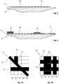
figure 3 est une vue de dessus d'un pli tissé, - La
figure 4 est une vue de dessus d'un pli tissé sur lequel sont rapportées des mèches de fibres qui illustre un mode de réalisation de l'invention, - Les
figures 5 et 6 sont des schémas qui illustrent les étapes de pose d'un pli tissé et d'une pluralité de mèches de fibres d'un procédé d'obtention d'une couche acoustique poreuse selon l'invention, - Les
figures 7A et 7B sont des vues de dessus qui illustrent différents agencements de mèches de fibres d'une couche acoustique poreuse. - Comme illustré sur la
figure 2 , un panneau acoustique 24 comprend une couche acoustique poreuse 26 sur une première face, en contact avec un flux d'air matérialisé par la flèche 28, une couche réflectrice 30 sur une seconde face et au moins une structure alvéolaire 32 intercalée entre la couche acoustique poreuse 26 et la couche réflectrice 30. - Selon un mode de réalisation, le panneau acoustique 24 comprend une seule structure alvéolaire 32. En variante, le panneau acoustique 24 comprend deux structures alvéolaires 32 superposées et séparées par une couche acoustique poreuse.
- A titre d'exemple, le panneau acoustique 24 est utilisé pour former une entrée d'air d'une nacelle d'un aéronef.
- Selon un mode de réalisation, la couche acoustique poreuse 26 comprend au moins un pli tissé 34 et une pluralité de mèches de fibres 36, 38, 40 positionnées sur une première face 42 du pli tissé 34 et orientées selon au moins deux directions sécantes.
- Selon un mode de réalisation, le pli tissé 34 est en résine thermoplastique, comme par exemple en polyétherétherkétone désigné par le sigle PEEK.
- Le pli tissé 34 comprend des fils de chaîne et de trame orientés selon deux directions perpendiculaires et espacés régulièrement, avec un pas inférieur ou égal à 0,3 mm. Préférentiellement, le pas entre les fils du pli tissé 34 est inférieur à 0,1 mm.
- Bien entendu, l'invention n'est pas limitée à ce mode de réalisation pour le pli tissé 34.
- Pour la présente demande, une mèche de fibres comprend une ou plusieurs fibres accolées les unes aux autres. La longueur d'une mèche de fibres 36, 38, 40 correspond à la plus grande dimension de la mèche de fibres. Lorsqu'une mèche de fibres 36, 38, 40 est plaquée contre le pli tissé 34, la largeur de la mèche de fibres 36, 38, 40 correspond à la dimension de la mèche de fibres parallèle au pli tissé 34 et perpendiculaire à la longueur. L'épaisseur de la mèche de fibres 36, 38, 40 correspond à la dimension de la mèche de fibres perpendiculaire au pli tissé 34 et à la longueur.
- Lorsqu'une mèche de fibres 36, 38, 40 comprend plusieurs fibres, ces dernières sont agencées de manière à former une bande avec une largeur nettement supérieure à l'épaisseur.
- Une mèche de fibres 36, 38, 40 a une largeur comprise entre 1 mm et plusieurs millimètres. Selon un mode de réalisation, les fibres des mèches sont en carbone et pré-imprégnées d'une résine thermoplastique, comme par exemple en polyétherétherkétone désigné par le sigle PEEK ou en polyétherimide désigné par le sigle PEI.
- Selon un mode de réalisation, les mèches de fibres 36, 38, 40 sont pré-imprégnées d'une résine dont la température de transformation est inférieure ou égale à celle de la résine du pli tissé 34.
- Ainsi, à titre d'exemple, l'usage d'une résine en polyétherimide pour les mèches de fibres 36, 38, 40 permet de limiter les risques de dégradation du pli tissé 34 réalisé en polyétherétherkétone, la température de fusion de la résine en polyétherétherkétone de l'ordre de 342°C étant supérieure à la plage de températures de transformation de la résine en polyétherimide comprise entre 217°C et 320°C.
- Selon une autre caractéristique de l'invention, les matériaux du pli tissé 34 et des mèches de fibres 36, 38, 40 sont choisis de manière à ce que les mèches de fibres 36, 38, 40 adhèrent directement sur le pli tissé 34. Ainsi, les mèches de fibres 36, 38, 40 ne bougent plus après avoir été déposées sur le pli tissée 34.
- Selon un agencement, les mèches de fibres 36 d'une première série sont orientées selon une première direction, par exemple parallèlement à l'axe de la nacelle, les mèches de fibres 38 d'une deuxième série sont orientées selon une deuxième direction perpendiculaire à la première direction, par exemple dans des plans perpendiculaires à l'axe de la nacelle, et les mèches de fibres 40 d'une troisième série sont orientées selon une troisième direction oblique, sécante aux première et deuxième directions.
- Pour chaque série, les mèches de fibres sont réparties selon un pas (espacement entre deux mèches de fibres consécutives) qui varie de 0 mm à plusieurs millimètres. Ainsi pour chaque série, le pas peut être constant ou variable.
- Ainsi, à titre d'exemple, pour la première série, le pas entre deux mèches de fibres 36.1 et 36.2 est nul et le pas entre deux mèches de fibres 36.2 et 36.3 est de l'ordre de quelques dixièmes de millimètres.
- A titre d'exemple, pour la deuxième série, le pas entre deux mèches de fibres 38.1 et 38.2 est nul, le pas entre deux mèches de fibres 38.3 et 38.4 est de l'ordre de quelques dixièmes de millimètres et le pas entre deux mèches de fibres 38.5 et 38.6 est de l'ordre du millimètre. Les mèches de fibres d'une même série peuvent ne pas avoir les mêmes dimensions. Ainsi, la mèche de fibres 36.1 a une largeur nettement inférieure à celle de la mèche de fibres 36.2. Quel que soit l'agencement, la couche acoustique poreuse 26 comprend au moins deux séries de mèches de fibres 36, 38 orientées selon deux directions sécantes pour délimiter entre les mèches de fibres des ouvertures 44 avec des dimensions qui peuvent varier de l'ordre du dixième de millimètres à plusieurs millimètres, l'espacement, la largeur et/ou l'orientation des mèches de fibres 36, 38, 40 étant déterminés en fonction des performances acoustiques recherchées.
- Le pli tissé 34 est optionnel. Il est mis en place selon la traînée parasite maximale admissible pour l'utilisation. Dans le cas d'un aéronef, il est envisageable de ne pas prévoir de pli tissé 34 si la couche acoustique poreuse 26 comprend des ouvertures 44 dont le diamètre est inférieur à 0,1 mm.
- Ainsi, il est possible de moduler le taux de surface ouverte zone par zone, sur toute la surface de la couche acoustique poreuse, et d'ajuster les dimensions des ouvertures 44 en fonction du traitement acoustique souhaité pour chaque zone. En conséquence, selon l'invention, les dimensions et orientations des perforations ainsi que le taux de surface ouverte sont définis selon les conditions locales (position, niveau de bruit, vitesse d'écoulement, géométrie du conduit...) et les performances acoustiques recherchées afin d'optimiser le traitement acoustique le long du panneau acoustique.
- A titre d'exemple, comme illustré sur la
figure 7A , la couche acoustique poreuse 26' comprend une première zone Z1 avec un taux de surface ouverte de l'ordre de 60%, une deuxième zone Z2 avec un taux de surface ouverte de l'ordre de 30% et d'autres zones Z3 à Z5 avec un taux de surface ouverte de l'ordre de 70%. - Comme illustré sur la
figure 7B , la couche acoustique poreuse 26" comprend une première zone Z1 avec un taux de surface ouverte de l'ordre de 60%, des zones Z2 et Z3 avec un taux de surface ouverte de 0% et des zones Z4 et Z5 avec un taux de surface ouverte de l'ordre de 30%. - Selon une autre caractéristique, la largeur, l'orientation et/ou l'espacement des mèches de fibres 36, 38, 40 sont déterminés en fonction du renforcement mécanique souhaité, par exemple pour renforcer certaines zones de la couche acoustique poreuse 26 et/ou pour favoriser la reprise des efforts selon une direction.
- Selon un mode de réalisation, les mèches de fibres 40.1 et 40.2 de la troisième série sont orientées parallèlement à la direction principale des efforts repris par la couche acoustique poreuse. A titre d'exemple, les mèches de fibres 40.1 et 40.2 sont orientées selon une direction à 45° pour favoriser la reprise des efforts orientés à 45° par rapport à l'axe de la nacelle.
- Selon un autre mode de réalisation, les mèches de fibres 40.1, 40.2 ont des longueurs inférieures aux dimensions de la couche acoustique poreuse 26 et ne s'étendent pas d'un bord à l'autre de la couche acoustique poreuse 26, afin d'obtenir une zone de renforcement Zr.
- Selon un premier mode opératoire illustré par les
figures 5 et 6 , un procédé d'obtention d'une couche acoustique poreuse comprend une première étape de dépose E1, sur une surface de dépose 46S d'un outillage 46 conformée selon la forme du panneau acoustique souhaitée, de mèches de fibres 36, 38, 40 selon au moins deux directions sécantes. - Après l'étape de dépose E1 des mèches de fibres 36, 38, 40, le procédé comprend une étape de consolidation E2 des mèches de fibres 36, 38, 40 pour obtenir une couche acoustique poreuse 26 rigide. Préférentiellement, l'étape de consolidation E2 est réalisée simultanément à l'étape de dépose E1.
- Selon un deuxième mode opératoire, le procédé comprend une étape de dépose Ep d'un pli tissé 34. Préférentiellement, le pli tissé 34 est déposé sur la surface de dépose 46S préalablement à l'étape de dépose E1 des mèches de fibres 36, 38, 40. En variante de ce deuxième mode opératoire, l'étape de dépose Ep est réalisée après l'étape de dépose E1 des mèches de fibres 36, 38, 40.
- Après les étapes de dépose E1 des mèches de fibres 36, 38, 40 et Ep du pli tissé 34, le procédé comprend une étape de consolidation E'2 des mèches de fibres 36, 38, 40 et une étape de consolidation E'2p du pli tissé 34 afin d'obtenir une couche acoustique poreuse 26 rigide.
- Selon une première variante, l'étape de consolidation E'2 des mèches de fibres 36, 38, 40 et l'étape E'2p de consolidation du pli tissé 34 sont réalisées simultanément.
- Selon une deuxième variante, le pli tissé 34 est consolidé préalablement à l'étape de dépose E1 des mèches de fibres 36, 38, 40 et l'étape E'2 est réalisée simultanément à l'étape de dépose E1 des mèches de fibres 36, 38, 40 par un dispositif de consolidation in-situ.
- Selon un troisième mode opératoire, le pli tissé 34 d'une part et les mèches de fibres 36, 38, 40 d'autre part sont déposés et consolidés séparément. En suivant, le pli tissé 34 et les mèches de fibres 36, 38, 40 sont assemblés par tout moyen approprié.
- L'étape de dépose E1 des mèches de fibres 36, 38, 40 est réalisée à l'aide d'une machine de placement pour déposer, sur la première face du pli tissé 34 ou sur la surface de dépose 46S, chaque mèche de fibres 36, 38, 40 selon un agencement prédéfini. Ainsi, les dimensions et orientations des mèches de fibre ainsi que l'espacement entre deux mèches de fibres posées consécutivement et le taux de surface ouverte de la couche acoustique poreuse 26 sont adaptés sur toute la surface de la couche en fonction de la performance acoustique souhaitée.
- Les mèches de fibres sont stockées sur au moins une bobine. La machine de placement peut comprendre plusieurs bobines avec des largeurs de mèches de fibres différentes.
- A titre d'exemple, une première bobine comprend une mèche de fibres avec une largeur de l'ordre de 1 mm et une deuxième bobine comprend une mèche de fibres avec une largeur de l'ordre de 6,35 mm.
- Lorsque la couche acoustique poreuse 26 est réalisée, elle est assemblée aux autres éléments du panneau acoustique 24.
- Selon les configurations, il est possible de positionner le pli tissé 34 entre les mèches de fibres 36, 38, 40 et la structure alvéolaire 32 ou de positionner les mèches de fibres 36, 38, 40 entre le pli tissé 34 et la structure alvéolaire 32.
- Selon un mode opératoire, après la réalisation de la couche acoustique poreuse 26, la jonction entre la structure alvéolaire 32 et la couche acoustique poreuse 26 est obtenue par polymérisation.
- Selon l'invention, il est possible d'adapter le taux de surface ouverte des différentes zones d'une couche acoustique poreuse en fonction des performances acoustiques recherchées pour chacune de ces zones
- Le taux de surface ouverte peut être ajusté en fonction de la largeur de fibres 36, 38, 40, de l'orientation des mèches de fibres 36, 38, 40 et/ou de l'espacement entre les mèches de fibres 36, 38, 40. Le taux de surface ouverte peut également être ajusté en fonction des dimensions des interstices du pli tissé 34.
- Selon un autre avantage, il est possible d'ajuster zone par zone le renforcement mécanique de la couche acoustique poreuse 26.
- Selon un autre avantage, il est possible de laisser un espacement inférieur à 0,3 mm entre les mèches de fibres pour obtenir ainsi des ouvertures 44 avec une section inférieure à 0,1 mm2. Cette dimension pour les ouvertures permet de générer une faible traînée parasite, de supprimer le pli tissé 34 et de pouvoir positionner le panneau acoustique dans des zones où une traînée parasite trop importante n'est pas tolérée.
Claims (12)
- Procédé d'obtention d'une couche acoustique poreuse caractérisé en ce qu'il comprend une étape de dépose (E1) d'une pluralité de mèches de fibres (36, 38, 40) réparties selon au moins deux séries orientées selon deux directions sécantes pour délimiter entre les mèches de fibres (36, 38, 40) des ouvertures (44) avec des dimensions qui varient, les mèches de fibres (36, 38, 40) comprenant une largeur, une orientation et/ou un espacement déterminés en fonction d'un taux de surface ouverte souhaité pour chaque zone de la couche acoustique poreuse afin de moduler le taux de surface ouverte zone par zone.
- Procédé d'obtention d'une couche acoustique poreuse selon la revendication 1, caractérisé en ce que la largeur, l'orientation et/ou l'espacement des mèches de fibres (36, 38, 40) sont déterminés en fonction du renforcement mécanique souhaité pour la couche acoustique poreuse.
- Procédé d'obtention d'une couche acoustique poreuse selon la revendication précédente, caractérisé en ce que les mèches de fibres (36) d'une première série sont orientées selon une première direction, les mèches de fibres (38) d'une deuxième série sont orientées selon une deuxième direction perpendiculaire à la première direction et les mèches de fibres (40) d'une troisième série sont orientées selon une troisième direction oblique, sécante aux première et deuxième directions et parallèle à une direction des efforts repris par la couche acoustique poreuse.
- Procédé d'obtention d'une couche acoustique poreuse selon l'une des revendications 1 à 3, caractérisé en ce que les mèches ont un espacement inférieur à 0,1 mm.
- Procédé d'obtention d'une couche acoustique poreuse selon l'une des revendications 1 à 3, caractérisé en ce qu'il comprend une étape de dépose (Ep) d'un pli tissé (34) comportant un pas inférieur à 0,1 mm.
- Procédé d'obtention d'une couche acoustique poreuse selon la revendication précédente, caractérisé en ce qu'il comprend une première étape de dépose du pli tissé (34) et une deuxième étape de dépose des mèches de fibres (36, 38, 40) sur le pli tissé (34), les mèches de fibres (36, 38, 40) et le pli tissé (34) étant réalisés en des matériaux configurés pour permettre aux mèches de fibres (36, 38, 40) d'adhérer directement sur le pli tissé (34).
- Procédé d'obtention d'une couche acoustique poreuse selon l'une des revendications précédentes, caractérisé en ce qu'il comprend une étape de consolidation (E2) des mèches de fibres (36, 38, 40) réalisée simultanément à l'étape de dépose (E1) des mèches de fibres (36, 38, 40).
- Couche acoustique poreuse obtenue à partir du procédé d'obtention selon l'une des revendications précédentes, caractérisée en ce qu'elle comprend une pluralité de mèches de fibres (36, 38, 40) réparties selon au moins deux séries orientées selon deux directions sécantes pour délimiter entre les mèches de fibres (36, 38, 40) des ouvertures (44) avec des dimensions qui varient, les mèches de fibres (36, 38, 40) comprenant une largeur, une orientation et/ou un espacement déterminés en fonction d'un taux de surface ouverte souhaité pour chaque zone de la couche acoustique poreuse (36, 38, 40) afin de moduler le taux de surface ouverte zone par zone.
- Couche acoustique poreuse selon la revendication précédente, caractérisée en ce que la largeur, l'orientation et/ou l'espacement des mèches de fibres (36, 38, 40) sont déterminés en fonction du renforcement mécanique souhaité pour la couche acoustique poreuse.
- Couche acoustique poreuse selon l'une des revendications 8 à 9, caractérisée en ce que les mèches ont un espacement inférieur à 0,1 mm.
- Couche acoustique poreuse selon l'une des revendications 8 à 9, caractérisée en ce qu'elle comprend un pli tissé (34) comportant un pas inférieur à 0,1 mm.
- Panneau acoustique comprenant au moins une couche acoustique poreuse selon l'une des revendications 8 à 11.
Applications Claiming Priority (1)
| Application Number | Priority Date | Filing Date | Title |
|---|---|---|---|
| FR1663297A FR3061347A1 (fr) | 2016-12-23 | 2016-12-23 | Procede d'obtention d'une couche acoustique poreuse et couche acoustique poreuse ainsi obtenue |
Publications (2)
| Publication Number | Publication Date |
|---|---|
| EP3340237A1 true EP3340237A1 (fr) | 2018-06-27 |
| EP3340237B1 EP3340237B1 (fr) | 2022-07-13 |
Family
ID=58162887
Family Applications (1)
| Application Number | Title | Priority Date | Filing Date |
|---|---|---|---|
| EP17206081.6A Not-in-force EP3340237B1 (fr) | 2016-12-23 | 2017-12-08 | Procede d'obtention d'une couche acoustique poreuse et panneau acoustique comprenant la couche acoustique poreuse ainsi obtenue |
Country Status (4)
| Country | Link |
|---|---|
| US (1) | US20180182369A1 (fr) |
| EP (1) | EP3340237B1 (fr) |
| CN (1) | CN108237703B (fr) |
| FR (1) | FR3061347A1 (fr) |
Cited By (1)
| Publication number | Priority date | Publication date | Assignee | Title |
|---|---|---|---|---|
| CN115366445A (zh) * | 2022-10-25 | 2022-11-22 | 吉林国兴复合材料有限公司 | 一种35-50k碳纤维板材的生产工艺及碳纤维板材 |
Families Citing this family (4)
| Publication number | Priority date | Publication date | Assignee | Title |
|---|---|---|---|---|
| KR102200473B1 (ko) * | 2018-12-12 | 2021-01-08 | 한국과학기술연구원 | 흡음구조체 및 그 제조 방법 |
| FR3091670A1 (fr) * | 2019-01-15 | 2020-07-17 | Airbus Operations (S.A.S.) | Procédé de fabrication d’une structure acoustiquement résistive, structure acoustiquement résistive ainsi obtenue, panneau d’absorption acoustique comportant ladite structure acoustiquement résistive |
| FR3094828A1 (fr) * | 2019-04-08 | 2020-10-09 | Airbus Operations (S.A.S.) | Procédé de fabrication d’une couche poreuse d’une structure d’absorption acoustique, couche poreuse d’une structure d’absorption acoustique ainsi obtenue et structure d’absorption acoustique comprenant ladite couche poreuse |
| EP4169706A1 (fr) * | 2021-10-25 | 2023-04-26 | Airbus Operations SAS | Élément de peau résistive pour panneau acoustique destiné à un aéronef |
Citations (7)
| Publication number | Priority date | Publication date | Assignee | Title |
|---|---|---|---|---|
| FR2527367A1 (fr) * | 1982-05-19 | 1983-11-25 | Short Brothers Ltd | Dispositif pour l'attenuation de l'energie sonore et procede de fabrication de ce dispositif |
| US4504346A (en) * | 1982-11-30 | 1985-03-12 | Rolls-Royce Limited | Method of manufacturing a damped resonator acoustical panel |
| FR2823590A1 (fr) | 2001-04-17 | 2002-10-18 | Eads Airbus Sa | Panneau d'attenuation acoustique comportant une couche resistive a composante structurale renforcee |
| US20020157764A1 (en) * | 1999-12-24 | 2002-10-31 | Robert Andre | Method for making a sound reducing panel with resistive layer having structural property and resulting panel |
| US20120228051A1 (en) * | 2009-11-23 | 2012-09-13 | Aircelle | Acoustic skin for an aircraft nacelle acoustic panel |
| US8820477B1 (en) * | 2013-07-29 | 2014-09-02 | The Boeing Company | Acoustic panel |
| US20150030806A1 (en) * | 2013-07-26 | 2015-01-29 | Airbus Helicopters Deutschland GmbH | Sandwich type load bearing panel |
Family Cites Families (5)
| Publication number | Priority date | Publication date | Assignee | Title |
|---|---|---|---|---|
| US4671841A (en) * | 1986-01-06 | 1987-06-09 | Rohr Industries, Inc. | Method of making an acoustic panel with a triaxial open-weave face sheet |
| WO2016025564A2 (fr) * | 2014-08-13 | 2016-02-18 | Integrated Composite Products, Inc. | Article de renforcement |
| ES2710337T3 (es) * | 2016-05-04 | 2019-04-24 | Sontech Int Ab | Dispositivo de amortiguación de sonido para un conducto o cámara |
| KR101942258B1 (ko) * | 2016-09-29 | 2019-01-25 | (주)엘지하우시스 | 열가소성 복합재, 열가소성 복합재의 제조방법 및 패널 |
| EP3552814B1 (fr) * | 2018-04-09 | 2021-03-03 | SHPP Global Technologies B.V. | Composites renforcés par des fibres comprenant et/ou formés en partie à partir de couches fibreuses non tissées |
-
2016
- 2016-12-23 FR FR1663297A patent/FR3061347A1/fr not_active Ceased
-
2017
- 2017-12-08 EP EP17206081.6A patent/EP3340237B1/fr not_active Not-in-force
- 2017-12-20 US US15/848,818 patent/US20180182369A1/en not_active Abandoned
- 2017-12-22 CN CN201711399530.8A patent/CN108237703B/zh not_active Expired - Fee Related
Patent Citations (7)
| Publication number | Priority date | Publication date | Assignee | Title |
|---|---|---|---|---|
| FR2527367A1 (fr) * | 1982-05-19 | 1983-11-25 | Short Brothers Ltd | Dispositif pour l'attenuation de l'energie sonore et procede de fabrication de ce dispositif |
| US4504346A (en) * | 1982-11-30 | 1985-03-12 | Rolls-Royce Limited | Method of manufacturing a damped resonator acoustical panel |
| US20020157764A1 (en) * | 1999-12-24 | 2002-10-31 | Robert Andre | Method for making a sound reducing panel with resistive layer having structural property and resulting panel |
| FR2823590A1 (fr) | 2001-04-17 | 2002-10-18 | Eads Airbus Sa | Panneau d'attenuation acoustique comportant une couche resistive a composante structurale renforcee |
| US20120228051A1 (en) * | 2009-11-23 | 2012-09-13 | Aircelle | Acoustic skin for an aircraft nacelle acoustic panel |
| US20150030806A1 (en) * | 2013-07-26 | 2015-01-29 | Airbus Helicopters Deutschland GmbH | Sandwich type load bearing panel |
| US8820477B1 (en) * | 2013-07-29 | 2014-09-02 | The Boeing Company | Acoustic panel |
Cited By (1)
| Publication number | Priority date | Publication date | Assignee | Title |
|---|---|---|---|---|
| CN115366445A (zh) * | 2022-10-25 | 2022-11-22 | 吉林国兴复合材料有限公司 | 一种35-50k碳纤维板材的生产工艺及碳纤维板材 |
Also Published As
| Publication number | Publication date |
|---|---|
| US20180182369A1 (en) | 2018-06-28 |
| CN108237703B (zh) | 2022-01-25 |
| FR3061347A1 (fr) | 2018-06-29 |
| EP3340237B1 (fr) | 2022-07-13 |
| CN108237703A (zh) | 2018-07-03 |
Similar Documents
| Publication | Publication Date | Title |
|---|---|---|
| EP3340237B1 (fr) | Procede d'obtention d'une couche acoustique poreuse et panneau acoustique comprenant la couche acoustique poreuse ainsi obtenue | |
| EP2504832B1 (fr) | Panneau acoustique pour nacelle d'aeronef et procédé de fabrication correspondant | |
| CA2441477C (fr) | Panneau d'attenuation acoustique comportant une couche resistive a composante structurale renforcee | |
| EP1533787B1 (fr) | Panneau insonorisant à billes et procédé de réalisation | |
| CA2329832C (fr) | Procede de realisation d'une couche acoustiquement resistive, couche resistive obtenue et paroi utilisant une telle couche | |
| CA2365100C (fr) | Procede de fabrication d'un panneau d'attenuation acoustique a couche resistive a propriete structurale et panneau ainsi obtenu | |
| FR2922152A1 (fr) | Structure a ame alveolaire pour panneau acoustique | |
| FR2767411A1 (fr) | Couche acoustiquement resistive, procede de fabrication de cette couche et panneau acoustiquement absorbant muni d'au moins une telle couche | |
| FR3001409A1 (fr) | Procede de fabrication d'une structure alveolaire de forme courbee en materiau composite | |
| EP3017937B1 (fr) | Procede de fabrication d'un panneau en materiau composite integrant une protection contre la foudre et panneau en materiau composite fabrique selon ledit procede | |
| EP3664996B1 (fr) | Procédé de fabrication d'une structure fibreuse tubulaire à lobes | |
| EP4411726A1 (fr) | Structure alvéolaire d'un panneau d atténuation acoustique comprenant au moins une cloison configurée pour vibrer à une fréquence souhaitée, procédé de fabrication de ladite structure alvéolaire | |
| EP3723081B1 (fr) | Procédé de fabrication d'une couche poreuse d'une structure d'absorption acoustique, couche poreuse d'une structure d'absorption acoustique ainsi obtenue et structure d'absorption acoustique comprenant ladite couche poreuse | |
| EP4169706A1 (fr) | Élément de peau résistive pour panneau acoustique destiné à un aéronef | |
| EP1747552A1 (fr) | Peau perforee pour element acoustique, element acoustique et procede de fabrication | |
| FR3150138A1 (fr) | Nappe fibreuse multiaxiale comportant des elements metalliques pour la realisation d’une piece en materiau composite | |
| FR3157890A1 (fr) | Panneau acoustique pour un carter d’une turbomachine d’aeronef | |
| WO2026083020A1 (fr) | Procede de fabrication d'une structure alveolaire pour une piece en particulier d'une turbomachine d'aeronef | |
| EP4411725A1 (fr) | Structure alvéolaire d'un panneau d atténuation acoustique comprenant au moins un élément rapporté et configuré pour vibrer à une fréquence souhaitée, procédé de fabrication de ladite structure alvéolaire | |
| FR3155456A1 (fr) | Procede de fabrication d’une piece de turbomachine comprenant une structure alveolaire | |
| FR3165624A1 (fr) | Panneau acoustique comprenant des éléments acoustiques à section constante | |
| FR3119565A1 (fr) | Bande multicouche multi largeurs pour bobinage avec changement progressif de l’angle de dépose | |
| FR2960178A1 (fr) | Procede de depose de fibres pour l'obtention d'une structure raidie et structure ainsi obtenue |
Legal Events
| Date | Code | Title | Description |
|---|---|---|---|
| STAA | Information on the status of an ep patent application or granted ep patent |
Free format text: STATUS: EXAMINATION IS IN PROGRESS |
|
| PUAI | Public reference made under article 153(3) epc to a published international application that has entered the european phase |
Free format text: ORIGINAL CODE: 0009012 |
|
| 17P | Request for examination filed |
Effective date: 20171208 |
|
| AK | Designated contracting states |
Kind code of ref document: A1 Designated state(s): AL AT BE BG CH CY CZ DE DK EE ES FI FR GB GR HR HU IE IS IT LI LT LU LV MC MK MT NL NO PL PT RO RS SE SI SK SM TR |
|
| AX | Request for extension of the european patent |
Extension state: BA ME |
|
| RBV | Designated contracting states (corrected) |
Designated state(s): AL AT BE BG CH CY CZ DE DK EE ES FI FR GB GR HR HU IE IS IT LI LT LU LV MC MK MT NL NO PL PT RO RS SE SI SK SM TR |
|
| GRAP | Despatch of communication of intention to grant a patent |
Free format text: ORIGINAL CODE: EPIDOSNIGR1 |
|
| STAA | Information on the status of an ep patent application or granted ep patent |
Free format text: STATUS: GRANT OF PATENT IS INTENDED |
|
| INTG | Intention to grant announced |
Effective date: 20220425 |
|
| GRAS | Grant fee paid |
Free format text: ORIGINAL CODE: EPIDOSNIGR3 |
|
| GRAA | (expected) grant |
Free format text: ORIGINAL CODE: 0009210 |
|
| STAA | Information on the status of an ep patent application or granted ep patent |
Free format text: STATUS: THE PATENT HAS BEEN GRANTED |
|
| AK | Designated contracting states |
Kind code of ref document: B1 Designated state(s): AL AT BE BG CH CY CZ DE DK EE ES FI FR GB GR HR HU IE IS IT LI LT LU LV MC MK MT NL NO PL PT RO RS SE SI SK SM TR |
|
| REG | Reference to a national code |
Ref country code: CH Ref legal event code: EP |
|
| REG | Reference to a national code |
Ref country code: DE Ref legal event code: R096 Ref document number: 602017059409 Country of ref document: DE |
|
| REG | Reference to a national code |
Ref country code: AT Ref legal event code: REF Ref document number: 1504682 Country of ref document: AT Kind code of ref document: T Effective date: 20220815 |
|
| REG | Reference to a national code |
Ref country code: IE Ref legal event code: FG4D Free format text: LANGUAGE OF EP DOCUMENT: FRENCH |
|
| REG | Reference to a national code |
Ref country code: LT Ref legal event code: MG9D |
|
| REG | Reference to a national code |
Ref country code: NL Ref legal event code: MP Effective date: 20220713 |
|
| PG25 | Lapsed in a contracting state [announced via postgrant information from national office to epo] |
Ref country code: SE Free format text: LAPSE BECAUSE OF FAILURE TO SUBMIT A TRANSLATION OF THE DESCRIPTION OR TO PAY THE FEE WITHIN THE PRESCRIBED TIME-LIMIT Effective date: 20220713 Ref country code: RS Free format text: LAPSE BECAUSE OF FAILURE TO SUBMIT A TRANSLATION OF THE DESCRIPTION OR TO PAY THE FEE WITHIN THE PRESCRIBED TIME-LIMIT Effective date: 20220713 Ref country code: PT Free format text: LAPSE BECAUSE OF FAILURE TO SUBMIT A TRANSLATION OF THE DESCRIPTION OR TO PAY THE FEE WITHIN THE PRESCRIBED TIME-LIMIT Effective date: 20221114 Ref country code: NO Free format text: LAPSE BECAUSE OF FAILURE TO SUBMIT A TRANSLATION OF THE DESCRIPTION OR TO PAY THE FEE WITHIN THE PRESCRIBED TIME-LIMIT Effective date: 20221013 Ref country code: NL Free format text: LAPSE BECAUSE OF FAILURE TO SUBMIT A TRANSLATION OF THE DESCRIPTION OR TO PAY THE FEE WITHIN THE PRESCRIBED TIME-LIMIT Effective date: 20220713 Ref country code: LV Free format text: LAPSE BECAUSE OF FAILURE TO SUBMIT A TRANSLATION OF THE DESCRIPTION OR TO PAY THE FEE WITHIN THE PRESCRIBED TIME-LIMIT Effective date: 20220713 Ref country code: LT Free format text: LAPSE BECAUSE OF FAILURE TO SUBMIT A TRANSLATION OF THE DESCRIPTION OR TO PAY THE FEE WITHIN THE PRESCRIBED TIME-LIMIT Effective date: 20220713 Ref country code: FI Free format text: LAPSE BECAUSE OF FAILURE TO SUBMIT A TRANSLATION OF THE DESCRIPTION OR TO PAY THE FEE WITHIN THE PRESCRIBED TIME-LIMIT Effective date: 20220713 Ref country code: ES Free format text: LAPSE BECAUSE OF FAILURE TO SUBMIT A TRANSLATION OF THE DESCRIPTION OR TO PAY THE FEE WITHIN THE PRESCRIBED TIME-LIMIT Effective date: 20220713 |
|
| REG | Reference to a national code |
Ref country code: AT Ref legal event code: MK05 Ref document number: 1504682 Country of ref document: AT Kind code of ref document: T Effective date: 20220713 |
|
| PG25 | Lapsed in a contracting state [announced via postgrant information from national office to epo] |
Ref country code: PL Free format text: LAPSE BECAUSE OF FAILURE TO SUBMIT A TRANSLATION OF THE DESCRIPTION OR TO PAY THE FEE WITHIN THE PRESCRIBED TIME-LIMIT Effective date: 20220713 Ref country code: IS Free format text: LAPSE BECAUSE OF FAILURE TO SUBMIT A TRANSLATION OF THE DESCRIPTION OR TO PAY THE FEE WITHIN THE PRESCRIBED TIME-LIMIT Effective date: 20221113 Ref country code: HR Free format text: LAPSE BECAUSE OF FAILURE TO SUBMIT A TRANSLATION OF THE DESCRIPTION OR TO PAY THE FEE WITHIN THE PRESCRIBED TIME-LIMIT Effective date: 20220713 Ref country code: GR Free format text: LAPSE BECAUSE OF FAILURE TO SUBMIT A TRANSLATION OF THE DESCRIPTION OR TO PAY THE FEE WITHIN THE PRESCRIBED TIME-LIMIT Effective date: 20221014 |
|
| REG | Reference to a national code |
Ref country code: DE Ref legal event code: R097 Ref document number: 602017059409 Country of ref document: DE |
|
| PG25 | Lapsed in a contracting state [announced via postgrant information from national office to epo] |
Ref country code: SM Free format text: LAPSE BECAUSE OF FAILURE TO SUBMIT A TRANSLATION OF THE DESCRIPTION OR TO PAY THE FEE WITHIN THE PRESCRIBED TIME-LIMIT Effective date: 20220713 Ref country code: RO Free format text: LAPSE BECAUSE OF FAILURE TO SUBMIT A TRANSLATION OF THE DESCRIPTION OR TO PAY THE FEE WITHIN THE PRESCRIBED TIME-LIMIT Effective date: 20220713 Ref country code: DK Free format text: LAPSE BECAUSE OF FAILURE TO SUBMIT A TRANSLATION OF THE DESCRIPTION OR TO PAY THE FEE WITHIN THE PRESCRIBED TIME-LIMIT Effective date: 20220713 Ref country code: CZ Free format text: LAPSE BECAUSE OF FAILURE TO SUBMIT A TRANSLATION OF THE DESCRIPTION OR TO PAY THE FEE WITHIN THE PRESCRIBED TIME-LIMIT Effective date: 20220713 Ref country code: AT Free format text: LAPSE BECAUSE OF FAILURE TO SUBMIT A TRANSLATION OF THE DESCRIPTION OR TO PAY THE FEE WITHIN THE PRESCRIBED TIME-LIMIT Effective date: 20220713 |
|
| PLBE | No opposition filed within time limit |
Free format text: ORIGINAL CODE: 0009261 |
|
| STAA | Information on the status of an ep patent application or granted ep patent |
Free format text: STATUS: NO OPPOSITION FILED WITHIN TIME LIMIT |
|
| PG25 | Lapsed in a contracting state [announced via postgrant information from national office to epo] |
Ref country code: SK Free format text: LAPSE BECAUSE OF FAILURE TO SUBMIT A TRANSLATION OF THE DESCRIPTION OR TO PAY THE FEE WITHIN THE PRESCRIBED TIME-LIMIT Effective date: 20220713 Ref country code: EE Free format text: LAPSE BECAUSE OF FAILURE TO SUBMIT A TRANSLATION OF THE DESCRIPTION OR TO PAY THE FEE WITHIN THE PRESCRIBED TIME-LIMIT Effective date: 20220713 |
|
| 26N | No opposition filed |
Effective date: 20230414 |
|
| PG25 | Lapsed in a contracting state [announced via postgrant information from national office to epo] |
Ref country code: AL Free format text: LAPSE BECAUSE OF FAILURE TO SUBMIT A TRANSLATION OF THE DESCRIPTION OR TO PAY THE FEE WITHIN THE PRESCRIBED TIME-LIMIT Effective date: 20220713 |
|
| REG | Reference to a national code |
Ref country code: CH Ref legal event code: PL |
|
| REG | Reference to a national code |
Ref country code: BE Ref legal event code: MM Effective date: 20221231 |
|
| PG25 | Lapsed in a contracting state [announced via postgrant information from national office to epo] |
Ref country code: SI Free format text: LAPSE BECAUSE OF FAILURE TO SUBMIT A TRANSLATION OF THE DESCRIPTION OR TO PAY THE FEE WITHIN THE PRESCRIBED TIME-LIMIT Effective date: 20220713 Ref country code: LU Free format text: LAPSE BECAUSE OF NON-PAYMENT OF DUE FEES Effective date: 20221208 |
|
| PG25 | Lapsed in a contracting state [announced via postgrant information from national office to epo] |
Ref country code: LI Free format text: LAPSE BECAUSE OF NON-PAYMENT OF DUE FEES Effective date: 20221231 Ref country code: IE Free format text: LAPSE BECAUSE OF NON-PAYMENT OF DUE FEES Effective date: 20221208 Ref country code: CH Free format text: LAPSE BECAUSE OF NON-PAYMENT OF DUE FEES Effective date: 20221231 |
|
| PG25 | Lapsed in a contracting state [announced via postgrant information from national office to epo] |
Ref country code: BE Free format text: LAPSE BECAUSE OF NON-PAYMENT OF DUE FEES Effective date: 20221231 |
|
| PGFP | Annual fee paid to national office [announced via postgrant information from national office to epo] |
Ref country code: GB Payment date: 20231220 Year of fee payment: 7 |
|
| PG25 | Lapsed in a contracting state [announced via postgrant information from national office to epo] |
Ref country code: IT Free format text: LAPSE BECAUSE OF FAILURE TO SUBMIT A TRANSLATION OF THE DESCRIPTION OR TO PAY THE FEE WITHIN THE PRESCRIBED TIME-LIMIT Effective date: 20220713 |
|
| PGFP | Annual fee paid to national office [announced via postgrant information from national office to epo] |
Ref country code: FR Payment date: 20231222 Year of fee payment: 7 Ref country code: DE Payment date: 20231214 Year of fee payment: 7 |
|
| PG25 | Lapsed in a contracting state [announced via postgrant information from national office to epo] |
Ref country code: HU Free format text: LAPSE BECAUSE OF FAILURE TO SUBMIT A TRANSLATION OF THE DESCRIPTION OR TO PAY THE FEE WITHIN THE PRESCRIBED TIME-LIMIT; INVALID AB INITIO Effective date: 20171208 |
|
| PG25 | Lapsed in a contracting state [announced via postgrant information from national office to epo] |
Ref country code: CY Free format text: LAPSE BECAUSE OF FAILURE TO SUBMIT A TRANSLATION OF THE DESCRIPTION OR TO PAY THE FEE WITHIN THE PRESCRIBED TIME-LIMIT Effective date: 20220713 |
|
| PG25 | Lapsed in a contracting state [announced via postgrant information from national office to epo] |
Ref country code: MK Free format text: LAPSE BECAUSE OF FAILURE TO SUBMIT A TRANSLATION OF THE DESCRIPTION OR TO PAY THE FEE WITHIN THE PRESCRIBED TIME-LIMIT Effective date: 20220713 |
|
| PG25 | Lapsed in a contracting state [announced via postgrant information from national office to epo] |
Ref country code: MC Free format text: LAPSE BECAUSE OF FAILURE TO SUBMIT A TRANSLATION OF THE DESCRIPTION OR TO PAY THE FEE WITHIN THE PRESCRIBED TIME-LIMIT Effective date: 20220713 |
|
| PG25 | Lapsed in a contracting state [announced via postgrant information from national office to epo] |
Ref country code: TR Free format text: LAPSE BECAUSE OF FAILURE TO SUBMIT A TRANSLATION OF THE DESCRIPTION OR TO PAY THE FEE WITHIN THE PRESCRIBED TIME-LIMIT Effective date: 20220713 Ref country code: MC Free format text: LAPSE BECAUSE OF FAILURE TO SUBMIT A TRANSLATION OF THE DESCRIPTION OR TO PAY THE FEE WITHIN THE PRESCRIBED TIME-LIMIT Effective date: 20220713 |
|
| PG25 | Lapsed in a contracting state [announced via postgrant information from national office to epo] |
Ref country code: BG Free format text: LAPSE BECAUSE OF FAILURE TO SUBMIT A TRANSLATION OF THE DESCRIPTION OR TO PAY THE FEE WITHIN THE PRESCRIBED TIME-LIMIT Effective date: 20220713 |
|
| PG25 | Lapsed in a contracting state [announced via postgrant information from national office to epo] |
Ref country code: MT Free format text: LAPSE BECAUSE OF FAILURE TO SUBMIT A TRANSLATION OF THE DESCRIPTION OR TO PAY THE FEE WITHIN THE PRESCRIBED TIME-LIMIT Effective date: 20220713 |
|
| REG | Reference to a national code |
Ref country code: DE Ref legal event code: R119 Ref document number: 602017059409 Country of ref document: DE |
|
| GBPC | Gb: european patent ceased through non-payment of renewal fee |
Effective date: 20241208 |
|
| PG25 | Lapsed in a contracting state [announced via postgrant information from national office to epo] |
Ref country code: DE Free format text: LAPSE BECAUSE OF NON-PAYMENT OF DUE FEES Effective date: 20250701 |
|
| PG25 | Lapsed in a contracting state [announced via postgrant information from national office to epo] |
Ref country code: GB Free format text: LAPSE BECAUSE OF NON-PAYMENT OF DUE FEES Effective date: 20241208 |
|
| PG25 | Lapsed in a contracting state [announced via postgrant information from national office to epo] |
Ref country code: FR Free format text: LAPSE BECAUSE OF NON-PAYMENT OF DUE FEES Effective date: 20241231 |