EP3340186A1 - 3d adaptive form shaping and projecting device, system and method - Google Patents
3d adaptive form shaping and projecting device, system and method Download PDFInfo
- Publication number
- EP3340186A1 EP3340186A1 EP16206692.2A EP16206692A EP3340186A1 EP 3340186 A1 EP3340186 A1 EP 3340186A1 EP 16206692 A EP16206692 A EP 16206692A EP 3340186 A1 EP3340186 A1 EP 3340186A1
- Authority
- EP
- European Patent Office
- Prior art keywords
- form changing
- changing elements
- data
- unit
- elements
- Prior art date
- Legal status (The legal status is an assumption and is not a legal conclusion. Google has not performed a legal analysis and makes no representation as to the accuracy of the status listed.)
- Granted
Links
Images


Classifications
-
- H—ELECTRICITY
- H04—ELECTRIC COMMUNICATION TECHNIQUE
- H04N—PICTORIAL COMMUNICATION, e.g. TELEVISION
- H04N13/00—Stereoscopic video systems; Multi-view video systems; Details thereof
- H04N13/30—Image reproducers
- H04N13/388—Volumetric displays, i.e. systems where the image is built up from picture elements distributed through a volume
-
- B—PERFORMING OPERATIONS; TRANSPORTING
- B33—ADDITIVE MANUFACTURING TECHNOLOGY
- B33Y—ADDITIVE MANUFACTURING, i.e. MANUFACTURING OF THREE-DIMENSIONAL [3D] OBJECTS BY ADDITIVE DEPOSITION, ADDITIVE AGGLOMERATION OR ADDITIVE LAYERING, e.g. BY 3D PRINTING, STEREOLITHOGRAPHY OR SELECTIVE LASER SINTERING
- B33Y30/00—Apparatus for additive manufacturing; Details thereof or accessories therefor
Definitions
- the material which is able to flow is preferably a fluid, in particular a liquid material like oil or water or a gaseous material like air. This embodiment is beneficial since fluids can be pumped in a fast and highly controllable manner.
- a control unit is provided according to a further preferred embodiment of the present invention.
- the control unit preferably controls a valve unit and/or the actuator unit.
- the control unit controls material flow into and/or from respectively out of multiple changing elements at the same time.
- the valve unit and/or actuator unit is preferably controlled in dependency of a data set representing the shape of the outer surface of a reference object.
- the data set preferably provides data linked to the deformation or filling state of individual form changing elements. This embodiment is beneficial since a dynamic adaption of the surface can be caused, in particular in real time.
- a human face e.g. has multiple active muscles during talking or laughing, due to the present invention complex surface deformations occurring in such situations can be formed as 3D object or model.
- the projecting devices 5, 6, 7, 8 are operated in such a manner that only one section of the surface of the object is lighted, wherein the section is preferably smaller, in particular at least 5% or 10% or 15% or 20% smaller than the outer surface of the object 11 set up by form changing elements 3, 31, 32.
Landscapes
- Engineering & Computer Science (AREA)
- Multimedia (AREA)
- Signal Processing (AREA)
- Chemical & Material Sciences (AREA)
- Manufacturing & Machinery (AREA)
- Materials Engineering (AREA)
Abstract
Description
- The present inventions refers to a device for 3D form generating according to
claim 1, a system for 3D representation of an object having dynamic changes of the shape of its outer surface according toclaim 12, a method for generating a dynamic 3D object according toclaim 14 and a computer program product for executing said method. - The field of the invention is related to the "real 3D viewing experience" that can be used in projection systems, cybernetic applications, 3D chat environments, biomedical imaging, novel hologram display systems, 3D TVs, Sphere TVs, Cubic TVs, or other related TV systems.
- Publications in the field are e.g.
US2010316270A1 ,FR2838846A1 - It is not possible to turn around the object on these screens, the object are not touchable. Moreover, current projection systems either utilize 2D flat surfaces for showing arbitrary scenes or use fixed 3D models to ornament it with specific texture or patterns. They do not have any aim to create a real 3D display or object imitating the original counterpart.
- Thus, the before mentioned prior art has the disadvantages that an exact/real 3D object formation cannot be established. The prior art depends on static 2D surfaces or 3D holographic volumes based on the light source originating from the screen and imitating reality. They do not provide the simultaneous 3D object forming synchronized with shapes of the remote objects, e.g., in a 3D chat application where the conservation is realized with 3D copies of the people as if they are real. Some of the previous art uses fixed 3D models to ornament it with specific texture or patterns, but, they have not any aim to create a real 3D display with dynamic form shaping or real objects imitating the original counterpart.
- Thus, the object of the present invention is to provide a device, system and/or method which enables a better 3D viewing experience.
- The before mentioned object is solved by a device for 3D form generating according to
claim 1. Said device preferably comprises at least multiple at least sectionally hollow form changing elements. The form changing elements are preferably arranged in a stack like manner. The device further comprises a main hub for providing a material that is able to flow to the changing elements. Preferably at least the majority of the form changing elements are surrounding, in particularly fully or sectional, the main hub. Preferably each changing element is connected to the main hub. It is further or additionally conceivable that multiple form changing elements are grouped together and connected to the main hub. The device further comprises an actuator unit for causing material transfer of the material that is able to flow from or through the hub to the hollow section of the changing elements for adapting the outer surface of the device set up by the form changing elements. The device has a main central axis respectively main hub behaving as a skeleton of the object preferably carrying the material, in particular air, to fill the slices respectively form changing elements. The main hub or central axis needs not to be a simple structure but it can have branches to realize complicated 3D object appearances not only the ones which can be represented as layers of form changing element with mainly 2D cylindrical shapes. - This solution is beneficial since the device according to the present invention is supposed to give the real 3D viewing experience to the audience in a way that there is not any stereoscopic 3D environment realized with 2D screens and eyeglasses or any 3D holographic environment where a uniform medium is fed with light sources to create a illuminating 3D experience. In this solution, the object has a real surface and volume and it reflects light as in daily life experiences. In other words, it is similar to a robotic structure which can take the shape of any respectively many object/s while its skin is colored with lights projected from the projective devices. The object can be touched. May further be possible to turn it around and/or even carry it.
- Further preferred embodiments are subject-matter of the pending claims and of the following parts of the description.
- The form changing elements are made of an elastic material, in particular polymer material, according to a further preferred embodiment of the present invention. The form changing elements are additionally or alternatively individually connected or connectable to the main hub. Furthermore, the form changing elements are stacked or stackable in such a manner that most of the form changing elements are contacting two further form changing elements, wherein one further form changing element is arranged in axial direction of the stack contacting an upper section of a form changing element and wherein a second further form changing element is arranged in axial direction of the stack contacting a lower section of the same form changing element (which contacts the first form changing element). Each of these embodiments is beneficial since the concept of flexible elements mainly extending in two dimensions is very useful to form detailed surface properties.
- At least 10 or at least 20 or at least 50 or at least 100 form changing elements are provided according to a further preferred embodiment of the present invention. The form changing elements are stacked by means or a positioning element, in particular a frame or sleeve. It is additionally or alternatively conceivable that individual form changing elements are glued together. Highly preferably each form changing element is connected to the main hub. Each form changing element extends in axial direction (stacking direction) less than 10mm or 5mm, in particular less than 3mm or less than 1,5mm or less than 1 mm or less than 0,5mm or less than 0,1 mm or less than 0,05mm. This embodiment is beneficial since due to the number and size of form changing elements a high number or different field of usage can be addressed.
- E.g. the invention can be used in technical environments like cybernetic applications to realize adaptive skins for robots. In 3D chat applications to set up a conversation with a real 3D model. Consumer and entertainment technologies where toys or some personal objects can be formed imitating real counterparts, e.g., human or animal bodies. Biomedical technology where 3D anatomical forms can be utilized by doctors to better diagnosis and treatment results.
- The material which is able to flow is preferably a fluid, in particular a liquid material like oil or water or a gaseous material like air. This embodiment is beneficial since fluids can be pumped in a fast and highly controllable manner.
- Each form changing element comprises or forms a membrane to prevent escape of the material able to flow according to a further preferred embodiment of the present invention. Additionally or alternatively the form changing elements are expanding or shrinking in radial direction (orthogonal to stacking direction). Preferably each slice is protected with such a membrane to prevent the escape of the medium. Moreover, the hole or each hole of each slice respectively form changing element is connected to an actuator unit, in particular a pump unit, which is electronically controlled. Thus, preferably the majority of all form changing element or each form changing element can be controlled electronically in real time to form real time shaping, in particular of the outer surface of all form changing elements.
- A control unit is provided according to a further preferred embodiment of the present invention. The control unit preferably controls a valve unit and/or the actuator unit. The control unit controls material flow into and/or from respectively out of multiple changing elements at the same time. The valve unit and/or actuator unit is preferably controlled in dependency of a data set representing the shape of the outer surface of a reference object. The data set preferably provides data linked to the deformation or filling state of individual form changing elements. This embodiment is beneficial since a dynamic adaption of the surface can be caused, in particular in real time. A human face e.g. has multiple active muscles during talking or laughing, due to the present invention complex surface deformations occurring in such situations can be formed as 3D object or model.
- According to a further preferred embodiment of the present invention a projecting unit is provided, wherein the projecting unit comprises multiple projecting devices for projecting light onto the outer surface of the object generated by the stack of form changing elements, wherein the projections can be applied to the surface of the object generated by the stack of form changing elements in dependency of coordinates of the said surface. The projecting devices are arranged in a preferably defined manner around the object generated by the stack of form changing elements.
- A data source is provided according to a further preferred embodiment of the present invention, wherein the data source preferably provides source data, wherein the source data highly preferably comprises the data set representing the shape of the outer surface and/or modifications thereof and/or photo or video data to be projected on the object generated by the stack of form changing elements. The data source is a communication unit for transferring data via a communication path, in particular the internet, preferably in real time or a data medium, like a hard drive or CD or a data stick. The control unit preferably controls the projecting devices and/or the actuator unit and/or valve unit in synchronous manner, wherein changes of the shape of the outer surface of the object generated by the stack of form changing elements result in changes of the projection or vice versa.
- Thus, the device respectively system mainly changes the shapes of elastic slices in a very fast pace while forming a 3D appearance similar to 3D printing mechanism forming a 3D object with 2D dynamic slices of varying radius. Furthermore, the resulting slices are colored with light projected from projective devices placed around the object. The slices are at rest initially and if 3D object model data is provided the motor pumps or contracts air, water or oil inside the slices in coordination with the projected colors on the surface of the object.
- The present invention therefore comprises two major functions. The first major function is a design and utilizing of adaptive form shaping surfaces. The second major function is the usage of multiple projection devices in synchronization with form shaping elements, in particular form changing elements or slices.
- The shape of the object changes respectively at least some form changing elements are actuated in a time interval of less than 5 seconds, in particular of less than 2 seconds, in particular of less than 1 second, in particular of less than 0,5 seconds. The projection unit projecting light on the surface of the object is synchronized with the form changing of the object respectively the actuation of the form changing elements.
- The before mentioned object is also solved by a system for 3D representation of an object having dynamic changes of the shape of its outer surface. The system preferably comprises at least a device for 3D form generating, in particular according to any of
claims 1 to 11, and a projection unit. The device hereby provides an object having an outer surface, wherein the shape of the surface of said object is adapted in dependency of data representing form changes of a reference object. The projection unit preferably comprises multiple projection devices for projection light onto the outer surface of the object, wherein the light is projected onto the surface of the object in dependency of said data representing form changes of the reference object. The data representing form changes of the reference object is preferably received over a communication path, in particular the internet or a telephone line or TV signal line. Photo or video data representing the colors and/or shades of said object is also transmitted via that communication path furthermore, related audio data and/or auxiliary data like text data can be transmitted via that communication path. The projecting unit preferably projects said photo or video data onto the object. - Thus, a real 3D technology is provided contrary to today's virtual 3D technology. The developed solution in this invention is preferably based on two building blocks; the first is the design and utilize adaptive form shaping surface and the second one is using the multiple projection devices in synchronization with form shaping slices. By this way, 3D printing the object is formed slice by slice, the sliced structure is preferably made of an elastic material such as polymer and each slice radius can be adjustable and are connected to the central backbone respectively main hub. As the other building block, the color and the light intensities corresponding to the surfaces of the slices are projected on the 3D surface by using multiple projection devices distributed around the object. Thanks to the good reflector like slices surfaces, high brightness is provided. The change of the object is synchronized with the projected 3D image; by the projection devices and backbone of the pressure control are connected with a network.
- The mentioned object is further solved by a method for generating a dynamic 3D object according to
claim 14. This method preferably comprises the steps: Providing a device for 3D form generating, in particular according to any ofclaims 1 to 11, wherein the device provides an object having an outer surface; Providing an illumination unit, in particular a projection unit. The projection unit preferably comprises multiple projection devices for projection light onto the outer surface of the object. Adapting the shape of the surface of said object in dependency of data representing form changes of a reference object; and Adapting the illumination of, in particular the light projected onto, the surface of the object in dependency of said data representing form changes of the reference object. - The present invention further refers to a computer program product for executing a method according to
claim 14. - Further benefits, goals and features of the present invention will be described by the following specification of the attached figures, in which components of the invention are exemplarily illustrated. Components of the device, systems and methods according to the inventions, which match at least essentially with respect to their function can be marked with the same reference sign, wherein such components do not have to be marked or described in all figures.
- In the following the invention is just exemplarily described with respect to the attached figures.
-
-
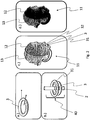
Fig. 1 shows a chart illustrating function interconnections of the present invention; -
Fig. 2 shows how the form changing elements are arranged and an exemplarily shaped head / face of a person; -
Fig. 3 shows an object formed by form changing elements and a projecting unit projecting light onto the object. - The system has preferably the following components, wherein each component has different tasks.
Reference number 1 indicates an actuating unit. Thisactuating unit 1 respectively motor driver preferably controls, in particularly electronically, the filling of theform change elements 3 respectively slices of theobject 11, in particular by pumping respectively actuation apump unit 10. Theobject 11 is preferably formed by preferably 2D layers ofform change elements 3 filled with air, water, oil or any other material. The term 2D layer hereby defines a form change element that extend into width and depth at least 5 times as long or at least 10 times as long or at least 20 times as long or at least 50 times as long as into height. - The
actuator unit 1 is preferably connected or connectable with apump unit 10. Thepump unit 10 preferably pumps or shrinks air, water or oil as fast as at least 5, 10, 20, 50 or 100 operations/second in order to realize a realistic form where e.g. the eyes will sense as a continuous and static instantaneous object shape. Pumping and shrinking processes can preferably be carried out simultaneously. - The
pump unit 10 is preferably connected respectively connectable with amain hub 2 or central axis. Themain hub 2 preferably carriers a material or material composition that is able to flow, like air, water or oil, in particularly to theform changing elements main hub 2 can be considered as the skeleton of the3D object 11. It is even possible that it can be mobile. It can have a very complicated structure including several branches depending on the object types to be formed. It is hereby conceivable that many different object types like human body parts or body parts of animals or products or parts of products are shaped with a device according to the present invention. - The
main hub 2 is preferably directly or indirectly connected, in particularly fluidly connected, with one, some, a group of or multiple groups of or allform changing elements main hub 2 into theform changing elements form changing elements main hub 2, respectively through themain hub 2 to thepump unit 10. - The
form changing elements -
Reference number object 11 to be formed onto the surfaces of theobject 11 respectively onto theouter surface 14 of theform changing elements form changing elements form changing elements projection devices object 11. Therefore, realistic 3D appearance of theobject 11 is realized by combining its shape with projected 3D image. Thesurfaces 14 of theform changing elements projection devices fig. 3 ) so that the change of theobject 11 is synchronized with the projected 3D image. - The first building block is described in
Figs. 2(a), (b) and(c) . Eachform shaping element Fig. 2(a) . Theslices - The change of radius is achieved by changing the pressure inside the hollow, in particular circular, volume. The pressure can be adapted by controlling the amount of the medium such as air, oil or water. The amount of these materials can be changed fast enough so that the human visual system senses a continuous change in the scene. The heights of the layers define the resolution of the
form shaping device 100. The smaller height and larger number of slices respectively form changingelements objects 11 with more detail and more resolution. All theseform changing elements main hub 2 where the medium respectively material, e.g., air, oil or water. Themain hub 2 preferably comprises at least one output and/or input hole providing flow of the medium inside theform changing elements Fig. 2(b) indicates with reference number 40 that the height of the stack results from the comulated height of the individualform changing elements form changing element - In
Fig. 2(c) , the sliced structure of the elastic material (such as polymer) basedobject 11 formation is shown. Similar to the 3D printing theobject 11 is formed slice by slice respectively form changingelement form changing element - Furthermore, each
form changing element main hub 2 is preferably provided for eachform changing element form changing element pump unit 10 which is preferably electronically controlled. Eachform changing element object 11. - In the second building block, the color and the light intensities corresponding to the surfaces of the slices are previously projected 12 on the 3D surface by using
multiple projection devices object 11. Therefore, realistic 3D appearance of theobject 11 is realized by combining its shape with projected 3D image. Thesurfaces 14 of theform changing elements projection devices object 11 is synchronized with the projected 3D image. It is conceivable that the projectingdevices object 11 set up byform changing elements -
Fig. 2d shows a photo of an example of anobject 11 generated by theinventive device 100. - The skeleton of each object can be designed by another algorithm by using the 3D modelling data of the object. The skeleton can be formed of multiple parts resembling a tree structure which can be adaptively formed with a special mechanical design. Therefore, as the diameter of the leaves of the tree gets smaller the diameter of the slices will be smaller to form smaller details in the 3D model.
- The slices are connected to the pumping axis as a cylindrical 3D structure with hole at the center where the diameter of the center is equal to the diameter of the pumping axis. The inner surface of the cylindrical slice with the hole includes two different regions. The upper and bottom parts of the inner surfaces are tightly connected to the axis in order to make the position of the slice stable. The middle part of the slice is empty and allows the fluidic connection with the pumping axis. Each slice can be controlled independently by a control unit placed before the empty fluidic hole inside the axis. The valves are the control units adapting the mechanical flow of the fluid for each individual slices.
-
Fig. 3 shows a 3D adaptive projection system, which can be used in factories, hospitals, schools, museums, AVMs, airports, etc. Furthermore, it can also be used in consumer electronics sector, health sector, military sector, etc. - This system is preferably connected to a
communication unit 15 for data exchange with a further computing device, in particular for data exchange with afurther device 100 according to the present invention. In case two or more than twodevices 100 according to the present invention are functionally coupled by means of acommunication unit 15, in particular an internet or Ian connection, the resulting arrangement can be considered as communication system. It is preferably conceivable that at least one camera unit, in particular a time of flight or real sense camera, is provided or present at everydevice 100 for capturing the shape changing of a surface of a real object, like a real human being. Said captured data is than preferably computed and transmitted via thecommunication unit 15 to one or multiplefurther devices 100, wherein that data preferably causes an actuation of the actuation unit and/or the projection unit of the one or multiplefurther devices 100. - Thus, the present invention refers to a
device 100 for 3D form generating, in particularly a 3D Adaptive Form Shaping and Projective System is proposed. The inventive device comprises at least multiple at least sectionally hollowform changing elements form changing elements main hub 2 for providing a material that is able to flow to the changingelements form changing elements main hub 2, wherein eachform changing element main hub 2, anactuator unit 1 for causing material transfer of the material that is able to flow from themain hub 2 or through themain hub 2 to the hollow section of theform changing elements outer surface 14 of anobject 11 set up by theform changing elements -
- 1
- Actuator unit / motor driver
- 2
- main hub / central axis
- 3
- form changing element / slice units
- 4
- 3D model of object
- 5
-
projection device 1 - 6
-
projection device 2 - 7
-
projection device 3 - 8
- projection device 4
- 9
- feedback
- 10
- pump unit
- 11
- 3D object
- 12
- projection
- 13
- surface of the object without projection
- 14
- outer surface of object
- 15
- communication unit / communication network
- 31
- first further form changing element
- 32
- second further form changing element
- 40
- height
- 100
- Device for 3D form generating
Claims (15)
- Device (100) for 3D form generating,
at least comprising
multiple hollow form changing elements (3, 31),wherein the form changing elements (3, 31, 32) are arranged in a stack like manner,a main hub (2) for providing a material that is able to flow to the changing elements (3,31,32),wherein at least the majority of the form changing elements (3, 31, 32) surrounds the main hub (2),wherein each form changing element (3, 31, 32) is connected to the main hub (2),an actuator unit (1) for causing material transfer of the material that is able to flow from the main hub (2) or through the main hub (2) to the hollow section of the form changing elements (3, 31, 32) for adapting the outer surface (14) of an object (11) set up by the form changing elements (3, 31, 32). - Device according to claim 1,
characterized in that
the form changing elements (3, 31, 32) are made of an elastic material, in particular polymer material,
the form changing elements (3, 31, 32) are individually connected or connectable to the main hub (2) and
the form changing elements (3, 31, 32) are stacked in such a manner that most of the form changing elements (3, 31, 32) are contacting two further form changing elements, wherein one further form changing element (31) is arranged in axial direction of the stack contacting an upper section of the form changing element (3) and wherein a second further form changing element (32) is arranged in axial direction of the stack contacting a lower section of the form changing element (3). - Device according to claim 1 or claim 2,
characterized in that
at least 10 or at least 20 or at least 50 or at least 100 form changing elements (3, 31, 32) are provided and stacked,
wherein each form changing element (3, 31, 32) extends in axial direction less than 5mm, in particular less than 3mm or less than 1,5mm or less than 1 mm or less than 0,5mm or less than 0,1 mm or less than 0,05mm. - Device according to any of the previous claims,
characterized in that
the material able to flow is a fluid, in particular a liquid material like oil or water or a gaseous material like air. - Device according to any of the previous claims,
characterized in that
each form changing element (3, 31, 32) comprises or forms a membrane to prevent escape of the material able to flow and/or
the form changing elements (3, 31, 32) are expanding or shrinking in radial direction. - Device according to any of the previous claims,
characterized in that
a control unit is provided,
wherein the control unit controls a valve unit and/or the actuator unit (1),
wherein the control unit controls material flow into and/or from multiple changing elements (3, 31, 32) at the same time,
wherein the valve unit and/or actuator unit is controlled in dependency of a data set representing the shape of the outer surface of a reference object,
wherein the data set provides data linked to the deformation or filling state of individual form changing elements (3, 31, 32). - Device according to any of the previous claims,
characterized in that
a projecting unit is provided,
wherein the projecting unit comprises multiple projecting devices (5, 6, 7, 8) for projecting light onto the outer surface (14) of the object (11) generated by the stack of form changing elements (3, 31, 32),
wherein the projections can be applied to the surface (14) of the object (11) generated by the stack of form changing elements (3, 31, 32) in dependency of coordinates of the said surface. - Device according to any of the previous claims,
characterized in that
the projecting devices (5, 6, 7, 8) are arranged in a defined manner around the object (11) generated by the stack of form changing elements (3, 31, 32). - Device according to any of the previous claims,
characterized in that
a data source is provided,
wherein the data source provides source data,
wherein the source data comprises:- the data set representing the shape of the outer surface and/or modifications thereof and- photo or video data to be projected on the object generated by the stack of form changing elements (3, 31, 32). - Device according to claim 9,
characterized in that
the data source is a communication unit (15) for transferring data via a communication path, in particular the internet, preferably in real time
or
a data medium. - Device according to any of the previous claims,
characterized in that
the control unit controls the projecting devices (5, 6, 7, 8) and the actuator unit (1) and/or valve unit in synchronous manner, wherein changes of the shape of the outer surface (14) of the object (11) generated by the stack of form changing elements (3, 31, 32) result in changes of the projection or vice versa. - System for 3D representation of an object (11) having dynamic changes of the shape of its outer surface,
at least comprising
a device for 3D form generating (100), in particular according to any of claims 1 to 11,wherein the device (100) provides an object (11) having an outer surface (14),wherein the shape of the surface (14) of said object (11) is adapted in dependency of data representing form changes of a reference object,an illumination unit, in particular projection unit,wherein the surface (14) of the object (14) is illuminated by the illumination unit in dependency of said data representing form changes of the reference object. - System according to claim 12,
characterized in that
the data representing form changes of the reference object is received over a communication path, in particular the internet or a telephone line or TV signal line,
wherein photo or video data representing the colors and/or shades of said object is also transferred via that communication path (15),wherein the illumination unit illuminates the object surface in dependency of said photo or video data. - Method for generating a dynamic 3D object,
Providing a device for 3D form generating (100), in particular according to any of claims 1 to 11,
wherein the device (100) provides an object (11) having an outer surface (14);
Providing an illumination unit, in particular a projection unit, for illuminating the surface if the object (11);
Adapting the shape of the surface (14) of said object (11) in dependency of data representing form changes of a reference object; and
Adapting the light illuminating the surface (14) of the object (11) in dependency of said data representing form changes of the reference object. - Computer program product for executing a method according to claim 14.
Priority Applications (2)
| Application Number | Priority Date | Filing Date | Title |
|---|---|---|---|
| EP16206692.2A EP3340186B1 (en) | 2016-12-23 | 2016-12-23 | 3d adaptive form shaping and projecting device, system and method |
| TR2017/02778A TR201702778A2 (en) | 2016-12-23 | 2017-02-23 | 3D Adaptive form shaping and projecting device, system and method |
Applications Claiming Priority (1)
| Application Number | Priority Date | Filing Date | Title |
|---|---|---|---|
| EP16206692.2A EP3340186B1 (en) | 2016-12-23 | 2016-12-23 | 3d adaptive form shaping and projecting device, system and method |
Publications (2)
| Publication Number | Publication Date |
|---|---|
| EP3340186A1 true EP3340186A1 (en) | 2018-06-27 |
| EP3340186B1 EP3340186B1 (en) | 2023-02-15 |
Family
ID=57799492
Family Applications (1)
| Application Number | Title | Priority Date | Filing Date |
|---|---|---|---|
| EP16206692.2A Active EP3340186B1 (en) | 2016-12-23 | 2016-12-23 | 3d adaptive form shaping and projecting device, system and method |
Country Status (2)
| Country | Link |
|---|---|
| EP (1) | EP3340186B1 (en) |
| TR (1) | TR201702778A2 (en) |
Citations (5)
| Publication number | Priority date | Publication date | Assignee | Title |
|---|---|---|---|---|
| US4661039A (en) * | 1983-10-20 | 1987-04-28 | Donaldson Company | Flexible-frame robot |
| US6168634B1 (en) * | 1999-03-25 | 2001-01-02 | Geoffrey W. Schmitz | Hydraulically energized magnetorheological replicant muscle tissue and a system and a method for using and controlling same |
| FR2838846A1 (en) | 2002-04-22 | 2003-10-24 | Delphine Software Internat | Real time 3D image generation system uses detailed projected two dimensional image on solid model with moving parts having erased relief |
| US20080188709A1 (en) * | 2007-02-05 | 2008-08-07 | Noam Gil | Vibrator device with inflatable, alterable accessories |
| US20100316270A1 (en) | 2007-12-20 | 2010-12-16 | Koninklijke Philips Electronics N.V. | 3d reconstruction of a body and of a body contour |
-
2016
- 2016-12-23 EP EP16206692.2A patent/EP3340186B1/en active Active
-
2017
- 2017-02-23 TR TR2017/02778A patent/TR201702778A2/en unknown
Patent Citations (5)
| Publication number | Priority date | Publication date | Assignee | Title |
|---|---|---|---|---|
| US4661039A (en) * | 1983-10-20 | 1987-04-28 | Donaldson Company | Flexible-frame robot |
| US6168634B1 (en) * | 1999-03-25 | 2001-01-02 | Geoffrey W. Schmitz | Hydraulically energized magnetorheological replicant muscle tissue and a system and a method for using and controlling same |
| FR2838846A1 (en) | 2002-04-22 | 2003-10-24 | Delphine Software Internat | Real time 3D image generation system uses detailed projected two dimensional image on solid model with moving parts having erased relief |
| US20080188709A1 (en) * | 2007-02-05 | 2008-08-07 | Noam Gil | Vibrator device with inflatable, alterable accessories |
| US20100316270A1 (en) | 2007-12-20 | 2010-12-16 | Koninklijke Philips Electronics N.V. | 3d reconstruction of a body and of a body contour |
Non-Patent Citations (2)
| Title |
|---|
| CHANDRAJIT L. BAJAJ; EDWARD J. COYLE; KWUN-NAN LIN, ARBITRARY TOPOLOGY SHAPE RECONSTRUCTION FROM PLANAR CROSS SECTIONS, pages 35 |
| DAE HO LEE; JOONG YULL PARK; EUN-JOONG LEE; YOON YOUNG CHOI; GU HAN KWON; BEOP-MIN KIM; SANG-HOON LEE: "Fabrication of three-dimensional microarray structures by controlling the thickness and elasticity of poly (dimethylsiloxane) membrane", BIOMED MICRODEVICES, vol. 12, 2010, pages 49 - 54, XP019766999 |
Also Published As
| Publication number | Publication date |
|---|---|
| TR201702778A2 (en) | 2018-07-23 |
| EP3340186B1 (en) | 2023-02-15 |
Similar Documents
| Publication | Publication Date | Title |
|---|---|---|
| Greengard | Virtual reality | |
| Niiyama et al. | Sticky actuator: Free-form planar actuators for animated objects | |
| Follmer et al. | Jamming user interfaces: programmable particle stiffness and sensing for malleable and shape-changing devices | |
| Lindlbauer et al. | Combining shape-changing interfaces and spatial augmented reality enables extended object appearance | |
| US11425351B2 (en) | Method and system for creating an out-of-body experience | |
| Marcus | The history of the future: sci-fi movies and HCI | |
| EP2994638A1 (en) | Reprogrammable shape change sheet, uses of the sheet and method of producing a shaped surface | |
| Lee et al. | Snakeskin-inspired 3D printable soft robot composed of multi-modular vacuum-powered actuators | |
| Ou et al. | TEI 2016 studio: Inflated curiosity | |
| Jørgensen | Constructing soft robot aesthetics: art, sensation, and Materiality in practice | |
| EP3340186B1 (en) | 3d adaptive form shaping and projecting device, system and method | |
| Stevens | Designing immersive 3D experiences: a designer's guide to creating realistic 3D experiences for extended reality | |
| Ascott | The cybernetic stance: My process and purpose | |
| CN101732867A (en) | Simulated eye | |
| Karpenko | AUGMENTED REALITY AND VIRTUAL REALITY IN LIGHT INSTALLATIONS AND NIGHT URBAN ENVIRONMENT. | |
| Kim et al. | EMPop: Pin Based Electromagnetic Actuation for Projection Mapping | |
| Andrade | Holographic reality: enhancing the artificial reality experience through interactive 3D holography | |
| Grasnick | Virtual Spaces: The Creation of Illusory Worlds | |
| Follmer | Dynamic physical affordances for shape-changing and deformable user interfaces | |
| CN122043768A (en) | Stereoscopic display device and method for switching modes | |
| Moioli | Fields of Immersion: Real Sculptures as Spaces | |
| Esfandiar | The room: design of a space as a social being-a speculative approach | |
| Li | Journey | |
| Sheehan | ‘A series of surfaces’: The New Sculpture and Cinema | |
| Park | Photosculpture and the politics of nostalgia: Counter-hegemonic aesthetics in contemporary artistic practice |
Legal Events
| Date | Code | Title | Description |
|---|---|---|---|
| PUAI | Public reference made under article 153(3) epc to a published international application that has entered the european phase |
Free format text: ORIGINAL CODE: 0009012 |
|
| STAA | Information on the status of an ep patent application or granted ep patent |
Free format text: STATUS: THE APPLICATION HAS BEEN PUBLISHED |
|
| AK | Designated contracting states |
Kind code of ref document: A1 Designated state(s): AL AT BE BG CH CY CZ DE DK EE ES FI FR GB GR HR HU IE IS IT LI LT LU LV MC MK MT NL NO PL PT RO RS SE SI SK SM TR |
|
| AX | Request for extension of the european patent |
Extension state: BA ME |
|
| STAA | Information on the status of an ep patent application or granted ep patent |
Free format text: STATUS: REQUEST FOR EXAMINATION WAS MADE |
|
| 17P | Request for examination filed |
Effective date: 20190102 |
|
| RBV | Designated contracting states (corrected) |
Designated state(s): AL AT BE BG CH CY CZ DE DK EE ES FI FR GB GR HR HU IE IS IT LI LT LU LV MC MK MT NL NO PL PT RO RS SE SI SK SM TR |
|
| STAA | Information on the status of an ep patent application or granted ep patent |
Free format text: STATUS: EXAMINATION IS IN PROGRESS |
|
| 17Q | First examination report despatched |
Effective date: 20200330 |
|
| GRAP | Despatch of communication of intention to grant a patent |
Free format text: ORIGINAL CODE: EPIDOSNIGR1 |
|
| STAA | Information on the status of an ep patent application or granted ep patent |
Free format text: STATUS: GRANT OF PATENT IS INTENDED |
|
| INTG | Intention to grant announced |
Effective date: 20220914 |
|
| GRAS | Grant fee paid |
Free format text: ORIGINAL CODE: EPIDOSNIGR3 |
|
| GRAA | (expected) grant |
Free format text: ORIGINAL CODE: 0009210 |
|
| STAA | Information on the status of an ep patent application or granted ep patent |
Free format text: STATUS: THE PATENT HAS BEEN GRANTED |
|
| AK | Designated contracting states |
Kind code of ref document: B1 Designated state(s): AL AT BE BG CH CY CZ DE DK EE ES FI FR GB GR HR HU IE IS IT LI LT LU LV MC MK MT NL NO PL PT RO RS SE SI SK SM TR |
|
| REG | Reference to a national code |
Ref country code: CH Ref legal event code: EP Ref country code: GB Ref legal event code: FG4D |
|
| REG | Reference to a national code |
Ref country code: DE Ref legal event code: R096 Ref document number: 602016077814 Country of ref document: DE |
|
| REG | Reference to a national code |
Ref country code: AT Ref legal event code: REF Ref document number: 1548622 Country of ref document: AT Kind code of ref document: T Effective date: 20230315 Ref country code: IE Ref legal event code: FG4D |
|
| REG | Reference to a national code |
Ref country code: LT Ref legal event code: MG9D |
|
| REG | Reference to a national code |
Ref country code: NL Ref legal event code: MP Effective date: 20230215 |
|
| REG | Reference to a national code |
Ref country code: AT Ref legal event code: MK05 Ref document number: 1548622 Country of ref document: AT Kind code of ref document: T Effective date: 20230215 |
|
| PG25 | Lapsed in a contracting state [announced via postgrant information from national office to epo] |
Ref country code: RS Free format text: LAPSE BECAUSE OF FAILURE TO SUBMIT A TRANSLATION OF THE DESCRIPTION OR TO PAY THE FEE WITHIN THE PRESCRIBED TIME-LIMIT Effective date: 20230215 Ref country code: PT Free format text: LAPSE BECAUSE OF FAILURE TO SUBMIT A TRANSLATION OF THE DESCRIPTION OR TO PAY THE FEE WITHIN THE PRESCRIBED TIME-LIMIT Effective date: 20230615 Ref country code: NO Free format text: LAPSE BECAUSE OF FAILURE TO SUBMIT A TRANSLATION OF THE DESCRIPTION OR TO PAY THE FEE WITHIN THE PRESCRIBED TIME-LIMIT Effective date: 20230515 Ref country code: NL Free format text: LAPSE BECAUSE OF FAILURE TO SUBMIT A TRANSLATION OF THE DESCRIPTION OR TO PAY THE FEE WITHIN THE PRESCRIBED TIME-LIMIT Effective date: 20230215 Ref country code: LV Free format text: LAPSE BECAUSE OF FAILURE TO SUBMIT A TRANSLATION OF THE DESCRIPTION OR TO PAY THE FEE WITHIN THE PRESCRIBED TIME-LIMIT Effective date: 20230215 Ref country code: LT Free format text: LAPSE BECAUSE OF FAILURE TO SUBMIT A TRANSLATION OF THE DESCRIPTION OR TO PAY THE FEE WITHIN THE PRESCRIBED TIME-LIMIT Effective date: 20230215 Ref country code: HR Free format text: LAPSE BECAUSE OF FAILURE TO SUBMIT A TRANSLATION OF THE DESCRIPTION OR TO PAY THE FEE WITHIN THE PRESCRIBED TIME-LIMIT Effective date: 20230215 Ref country code: ES Free format text: LAPSE BECAUSE OF FAILURE TO SUBMIT A TRANSLATION OF THE DESCRIPTION OR TO PAY THE FEE WITHIN THE PRESCRIBED TIME-LIMIT Effective date: 20230215 Ref country code: AT Free format text: LAPSE BECAUSE OF FAILURE TO SUBMIT A TRANSLATION OF THE DESCRIPTION OR TO PAY THE FEE WITHIN THE PRESCRIBED TIME-LIMIT Effective date: 20230215 |
|
| PG25 | Lapsed in a contracting state [announced via postgrant information from national office to epo] |
Ref country code: SE Free format text: LAPSE BECAUSE OF FAILURE TO SUBMIT A TRANSLATION OF THE DESCRIPTION OR TO PAY THE FEE WITHIN THE PRESCRIBED TIME-LIMIT Effective date: 20230215 Ref country code: PL Free format text: LAPSE BECAUSE OF FAILURE TO SUBMIT A TRANSLATION OF THE DESCRIPTION OR TO PAY THE FEE WITHIN THE PRESCRIBED TIME-LIMIT Effective date: 20230215 Ref country code: IS Free format text: LAPSE BECAUSE OF FAILURE TO SUBMIT A TRANSLATION OF THE DESCRIPTION OR TO PAY THE FEE WITHIN THE PRESCRIBED TIME-LIMIT Effective date: 20230615 Ref country code: GR Free format text: LAPSE BECAUSE OF FAILURE TO SUBMIT A TRANSLATION OF THE DESCRIPTION OR TO PAY THE FEE WITHIN THE PRESCRIBED TIME-LIMIT Effective date: 20230516 Ref country code: FI Free format text: LAPSE BECAUSE OF FAILURE TO SUBMIT A TRANSLATION OF THE DESCRIPTION OR TO PAY THE FEE WITHIN THE PRESCRIBED TIME-LIMIT Effective date: 20230215 |
|
| PG25 | Lapsed in a contracting state [announced via postgrant information from national office to epo] |
Ref country code: SM Free format text: LAPSE BECAUSE OF FAILURE TO SUBMIT A TRANSLATION OF THE DESCRIPTION OR TO PAY THE FEE WITHIN THE PRESCRIBED TIME-LIMIT Effective date: 20230215 Ref country code: RO Free format text: LAPSE BECAUSE OF FAILURE TO SUBMIT A TRANSLATION OF THE DESCRIPTION OR TO PAY THE FEE WITHIN THE PRESCRIBED TIME-LIMIT Effective date: 20230215 Ref country code: EE Free format text: LAPSE BECAUSE OF FAILURE TO SUBMIT A TRANSLATION OF THE DESCRIPTION OR TO PAY THE FEE WITHIN THE PRESCRIBED TIME-LIMIT Effective date: 20230215 Ref country code: DK Free format text: LAPSE BECAUSE OF FAILURE TO SUBMIT A TRANSLATION OF THE DESCRIPTION OR TO PAY THE FEE WITHIN THE PRESCRIBED TIME-LIMIT Effective date: 20230215 Ref country code: CZ Free format text: LAPSE BECAUSE OF FAILURE TO SUBMIT A TRANSLATION OF THE DESCRIPTION OR TO PAY THE FEE WITHIN THE PRESCRIBED TIME-LIMIT Effective date: 20230215 |
|
| REG | Reference to a national code |
Ref country code: DE Ref legal event code: R097 Ref document number: 602016077814 Country of ref document: DE |
|
| PG25 | Lapsed in a contracting state [announced via postgrant information from national office to epo] |
Ref country code: SK Free format text: LAPSE BECAUSE OF FAILURE TO SUBMIT A TRANSLATION OF THE DESCRIPTION OR TO PAY THE FEE WITHIN THE PRESCRIBED TIME-LIMIT Effective date: 20230215 |
|
| PLBE | No opposition filed within time limit |
Free format text: ORIGINAL CODE: 0009261 |
|
| STAA | Information on the status of an ep patent application or granted ep patent |
Free format text: STATUS: NO OPPOSITION FILED WITHIN TIME LIMIT |
|
| 26N | No opposition filed |
Effective date: 20231116 |
|
| PG25 | Lapsed in a contracting state [announced via postgrant information from national office to epo] |
Ref country code: SI Free format text: LAPSE BECAUSE OF FAILURE TO SUBMIT A TRANSLATION OF THE DESCRIPTION OR TO PAY THE FEE WITHIN THE PRESCRIBED TIME-LIMIT Effective date: 20230215 |
|
| PG25 | Lapsed in a contracting state [announced via postgrant information from national office to epo] |
Ref country code: IT Free format text: LAPSE BECAUSE OF FAILURE TO SUBMIT A TRANSLATION OF THE DESCRIPTION OR TO PAY THE FEE WITHIN THE PRESCRIBED TIME-LIMIT Effective date: 20230215 |
|
| REG | Reference to a national code |
Ref country code: CH Ref legal event code: PL |
|
| PG25 | Lapsed in a contracting state [announced via postgrant information from national office to epo] |
Ref country code: LU Free format text: LAPSE BECAUSE OF NON-PAYMENT OF DUE FEES Effective date: 20231223 |
|
| PG25 | Lapsed in a contracting state [announced via postgrant information from national office to epo] |
Ref country code: MC Free format text: LAPSE BECAUSE OF FAILURE TO SUBMIT A TRANSLATION OF THE DESCRIPTION OR TO PAY THE FEE WITHIN THE PRESCRIBED TIME-LIMIT Effective date: 20230215 |
|
| REG | Reference to a national code |
Ref country code: BE Ref legal event code: MM Effective date: 20231231 |
|
| PG25 | Lapsed in a contracting state [announced via postgrant information from national office to epo] |
Ref country code: MC Free format text: LAPSE BECAUSE OF FAILURE TO SUBMIT A TRANSLATION OF THE DESCRIPTION OR TO PAY THE FEE WITHIN THE PRESCRIBED TIME-LIMIT Effective date: 20230215 Ref country code: LU Free format text: LAPSE BECAUSE OF NON-PAYMENT OF DUE FEES Effective date: 20231223 |
|
| PG25 | Lapsed in a contracting state [announced via postgrant information from national office to epo] |
Ref country code: IE Free format text: LAPSE BECAUSE OF NON-PAYMENT OF DUE FEES Effective date: 20231223 |
|
| PG25 | Lapsed in a contracting state [announced via postgrant information from national office to epo] |
Ref country code: BE Free format text: LAPSE BECAUSE OF NON-PAYMENT OF DUE FEES Effective date: 20231231 |
|
| PG25 | Lapsed in a contracting state [announced via postgrant information from national office to epo] |
Ref country code: FR Free format text: LAPSE BECAUSE OF NON-PAYMENT OF DUE FEES Effective date: 20231231 |
|
| PG25 | Lapsed in a contracting state [announced via postgrant information from national office to epo] |
Ref country code: CH Free format text: LAPSE BECAUSE OF NON-PAYMENT OF DUE FEES Effective date: 20231231 |
|
| PG25 | Lapsed in a contracting state [announced via postgrant information from national office to epo] |
Ref country code: IE Free format text: LAPSE BECAUSE OF NON-PAYMENT OF DUE FEES Effective date: 20231223 Ref country code: FR Free format text: LAPSE BECAUSE OF NON-PAYMENT OF DUE FEES Effective date: 20231231 Ref country code: CH Free format text: LAPSE BECAUSE OF NON-PAYMENT OF DUE FEES Effective date: 20231231 Ref country code: BE Free format text: LAPSE BECAUSE OF NON-PAYMENT OF DUE FEES Effective date: 20231231 |
|
| PG25 | Lapsed in a contracting state [announced via postgrant information from national office to epo] |
Ref country code: BG Free format text: LAPSE BECAUSE OF FAILURE TO SUBMIT A TRANSLATION OF THE DESCRIPTION OR TO PAY THE FEE WITHIN THE PRESCRIBED TIME-LIMIT Effective date: 20230215 |
|
| PG25 | Lapsed in a contracting state [announced via postgrant information from national office to epo] |
Ref country code: BG Free format text: LAPSE BECAUSE OF FAILURE TO SUBMIT A TRANSLATION OF THE DESCRIPTION OR TO PAY THE FEE WITHIN THE PRESCRIBED TIME-LIMIT Effective date: 20230215 |
|
| PG25 | Lapsed in a contracting state [announced via postgrant information from national office to epo] |
Ref country code: CY Free format text: LAPSE BECAUSE OF FAILURE TO SUBMIT A TRANSLATION OF THE DESCRIPTION OR TO PAY THE FEE WITHIN THE PRESCRIBED TIME-LIMIT; INVALID AB INITIO Effective date: 20161223 |
|
| PG25 | Lapsed in a contracting state [announced via postgrant information from national office to epo] |
Ref country code: HU Free format text: LAPSE BECAUSE OF FAILURE TO SUBMIT A TRANSLATION OF THE DESCRIPTION OR TO PAY THE FEE WITHIN THE PRESCRIBED TIME-LIMIT; INVALID AB INITIO Effective date: 20161223 |
|
| PGFP | Annual fee paid to national office [announced via postgrant information from national office to epo] |
Ref country code: TR Payment date: 20251219 Year of fee payment: 10 |
|
| PGFP | Annual fee paid to national office [announced via postgrant information from national office to epo] |
Ref country code: GB Payment date: 20260128 Year of fee payment: 10 |
|
| PGFP | Annual fee paid to national office [announced via postgrant information from national office to epo] |
Ref country code: DE Payment date: 20260223 Year of fee payment: 10 |