EP3340165A1 - Method of color gamut mapping input colors of an input ldr content into output colors forming an output hdr content - Google Patents

Method of color gamut mapping input colors of an input ldr content into output colors forming an output hdr content Download PDF

Info

Publication number
EP3340165A1
EP3340165A1 EP16306735.8A EP16306735A EP3340165A1 EP 3340165 A1 EP3340165 A1 EP 3340165A1 EP 16306735 A EP16306735 A EP 16306735A EP 3340165 A1 EP3340165 A1 EP 3340165A1
Authority
EP
European Patent Office
Prior art keywords
color
lightness
mapping
color gamut
output
Prior art date
Legal status (The legal status is an assumption and is not a legal conclusion. Google has not performed a legal analysis and makes no representation as to the accuracy of the status listed.)
Withdrawn
Application number
EP16306735.8A
Other languages
German (de)
French (fr)
Inventor
Mozhdeh Seifi
Erik Reinhard
Current Assignee (The listed assignees may be inaccurate. Google has not performed a legal analysis and makes no representation or warranty as to the accuracy of the list.)
Thomson Licensing SAS
Original Assignee
Thomson Licensing SAS
Priority date (The priority date is an assumption and is not a legal conclusion. Google has not performed a legal analysis and makes no representation as to the accuracy of the date listed.)
Filing date
Publication date
Application filed by Thomson Licensing SAS filed Critical Thomson Licensing SAS
Priority to EP16306735.8A priority Critical patent/EP3340165A1/en
Priority to PCT/EP2017/082559 priority patent/WO2018114509A1/en
Publication of EP3340165A1 publication Critical patent/EP3340165A1/en
Withdrawn legal-status Critical Current

Links

Images

Classifications

    • GPHYSICS
    • G06COMPUTING OR CALCULATING; COUNTING
    • G06TIMAGE DATA PROCESSING OR GENERATION, IN GENERAL
    • G06T5/00Image enhancement or restoration
    • G06T5/90Dynamic range modification of images or parts thereof
    • G06T5/92Dynamic range modification of images or parts thereof based on global image properties
    • HELECTRICITY
    • H04ELECTRIC COMMUNICATION TECHNIQUE
    • H04NPICTORIAL COMMUNICATION, e.g. TELEVISION
    • H04N9/00Details of colour television systems
    • H04N9/64Circuits for processing colour signals
    • H04N9/68Circuits for processing colour signals for controlling the amplitude of colour signals, e.g. automatic chroma control circuits
    • GPHYSICS
    • G09EDUCATION; CRYPTOGRAPHY; DISPLAY; ADVERTISING; SEALS
    • G09GARRANGEMENTS OR CIRCUITS FOR CONTROL OF INDICATING DEVICES USING STATIC MEANS TO PRESENT VARIABLE INFORMATION
    • G09G5/00Control arrangements or circuits for visual indicators common to cathode-ray tube indicators and other visual indicators
    • G09G5/10Intensity circuits
    • HELECTRICITY
    • H04ELECTRIC COMMUNICATION TECHNIQUE
    • H04NPICTORIAL COMMUNICATION, e.g. TELEVISION
    • H04N1/00Scanning, transmission or reproduction of documents or the like, e.g. facsimile transmission; Details thereof
    • H04N1/46Colour picture communication systems
    • H04N1/56Processing of colour picture signals
    • H04N1/60Colour correction or control
    • H04N1/6058Reduction of colour to a range of reproducible colours, e.g. to ink- reproducible colour gamut
    • GPHYSICS
    • G06COMPUTING OR CALCULATING; COUNTING
    • G06TIMAGE DATA PROCESSING OR GENERATION, IN GENERAL
    • G06T2207/00Indexing scheme for image analysis or image enhancement
    • G06T2207/20Special algorithmic details
    • G06T2207/20172Image enhancement details
    • G06T2207/20208High dynamic range [HDR] image processing
    • GPHYSICS
    • G09EDUCATION; CRYPTOGRAPHY; DISPLAY; ADVERTISING; SEALS
    • G09GARRANGEMENTS OR CIRCUITS FOR CONTROL OF INDICATING DEVICES USING STATIC MEANS TO PRESENT VARIABLE INFORMATION
    • G09G2320/00Control of display operating conditions
    • G09G2320/02Improving the quality of display appearance
    • G09G2320/0271Adjustment of the gradation levels within the range of the gradation scale, e.g. by redistribution or clipping
    • GPHYSICS
    • G09EDUCATION; CRYPTOGRAPHY; DISPLAY; ADVERTISING; SEALS
    • G09GARRANGEMENTS OR CIRCUITS FOR CONTROL OF INDICATING DEVICES USING STATIC MEANS TO PRESENT VARIABLE INFORMATION
    • G09G2320/00Control of display operating conditions
    • G09G2320/06Adjustment of display parameters
    • G09G2320/0666Adjustment of display parameters for control of colour parameters, e.g. colour temperature

Definitions

  • the invention relates to the field of inverse-tone mapping a LDR color content into a HDR color content.
  • HDR high dynamic range imaging
  • HDR technologies focus on capturing, processing and displaying content of a higher dynamic range.
  • a number of HDR display devices have appeared and cameras capable of capturing an increased dynamic range are being developed, there is still a very limited amount of HDR content available.
  • iTMO reverse or inverse tone mapping operators
  • LDR low dynamic range
  • ITMOs take a conventional image as input (from here on referred to as LDR for low dynamic range), and expand the luminance range of the image, generally in a non-linear manner.
  • LDR low dynamic range
  • Such a luminance processing may or may not be spatially varying, where spatially varying processing may reduce the amplification of artifacts at the cost of longer processing times.
  • Changes in luminance levels may create images that may appear too color saturated, or not saturated enough. This is notably due to a quirk of the human visual system, which appears to interpret brighter scenes as being more saturated, even if the saturation encoded in the pixels is not affected. This is known as the Hunt effect.
  • Image and video content can generally be represented in different color spaces.
  • an RGB color space can be understood as a three-dimensional volume in a coordinate system defined by a red, a green and a blue primaries.
  • the minimum and maximum values of the red, green and blue components representing colors in this RGB color space define the extent of a volume.
  • the boundary of this volume is often referred to as a color gamut.
  • RGB color spaces have usually a gamut boundary that is characterized by a cubic shape.
  • Values of the red, green and blue components that represent colors may be converted into other color spaces, and such a conversion may distort the shape of the gamut boundary. For instance, converting an RGB color space into the perceptually more uniform CIE L*a*b* color space results in an irregular gamut boundary. Conversions between different RGB color spaces, although each cubic in shape, correspond generally to rotation and/or scaling with respect to each other, dependent on the choice of primaries defining these color spaces. This is for instance the case for the two RGB color spaces defined by the ITU-R Rec. BT.709 and ITU-R Rec. BT.2020 standards. This means that representation of a color content specified in one RGB color space can typically be converted in another RGB color space through a linear matrix transform.
  • the application of a tone mapping algorithm may map colors of a content outside of a gamut in which colors of the image should be included, in order, for instance, to be displayed.
  • the application of an inverse tone mapping algorithm may produce colors that are outside such a color gamut.
  • out-of-gamut colors are generally repositioned within the color gamut by means of a gamut mapping algorithm added to the tone or inverse tone mapping algorithm.
  • mapping operations are generally carried out in an appropriately chosen color space.
  • a perceptual color space is generally used for such mapping operations, as in such a color space, Euclidean distance can be assumed to be a reasonable metric of perceptual distance.
  • Such color spaces will be referred to in the following as "cylindrical color spaces", because hue is calculated as an angle, taking a range of values between 0 and 360 degrees.
  • the well-known CIELab and IPT perceptual color spaces can be converted into cylindrical color spaces.
  • the lightness L remains unchanged relative to CIELab.
  • the resulting color space is referred to as LCh.
  • the lightness I remains unchanged relative to the IPT space.
  • the resulting color space is then referred to as ICH.
  • nonlinear definitions of the saturation with respect to chroma and lightness will be used instead.
  • CIELab and IPT can be defined as transformations from the XYZ color space, it is assumed known how conversions from any RGB color space to CIELab and IPT may be performed.
  • Any given display device can be characterized in terms of its color gamut and dynamic range.
  • the color content that may be received by such a device may have a different color gamut and a different dynamic range. If the display device has a wider gamut than this color content, it may be advantageous to expand color values representing colors of the content to better match its color gamut, thereby enhancing and representing colors of the content such that full advantage of the color gamut capabilities of the display device is obtained. Similarly, if the peak luminance of the display device exceeds that of the content, then the dynamic luminance range of the content may be expanded to match that of the display. All such adjustments should be carried out such that no colors of the content are mapped outside the display's color gamut.
  • a color space (as discussed in the previous paragraph) is no more than a coordinate system, whereas a color gamut describes a boundary within such a coordinate system.
  • a current trend is toward the diversification of display capabilities.
  • Professional content may be graded to a certain specification of color gamut and dynamic range. Some display devices will have a higher specification while others may be lower. At the same time, display devices may receive color content not specifically graded to match its capabilities. In such cases, a color management system is required that can make the adjustments.
  • Partial solutions to a complete color management system exist, and may be combined to form a system that includes tone mapping, inverse tone mapping, chroma management as well as gamut boundary management.
  • tone mapping inverse tone mapping
  • chroma management as well as gamut boundary management.
  • the complexity of the combined solutions may be unnecessarily high, and may be visually sub-optimal.
  • existing ITMO solutions focus on (perceptually) reproducing the appearance of the original scene and rely on strict assumptions about the content.
  • they focus on the expansion of the luminance channel of an LDR content, taking into account the maximum luminance that is reproducible by the display device, i.e. its peak luminance.
  • some state-of-art iTMO algorithms perform chroma correction on the chromatic channels of this content in the corresponding color space (e.g., YCbCr for television content).
  • This chroma correction is generally designed to keep the visual aspects of the LDR content (e.g., saturation), without any control with regard to the actual chromatic boundaries of the color gamut of the display device, i.e. of the target color gamut. It means that iTMO algorithms may adapt a color content with respect to the luminance boundaries of a target color gamut, without any regard to the chromatic ones. This in return results in out-of-gamut chromatic content that is either clipped by the display device when the content is displayed, or should be mapped into the target gamut in a complementary mapping step. Note that such a target gamut can be that of a hypothetical display device, for instance the output container color space defined by the standard BT.2020.
  • An aim of the invention is to process simultaneously the luminance channel and the chromatic channels of a color content, instead of processing these channels separately as in the prior art.
  • An aim of the invention is also to perform this process along a mapping curve which is different from a straight line, to mean a non-linear relationship between luminance or lightness and chroma.
  • Such a simultaneous process will advantageously enable any iTMO algorithm to increase the dynamic range of a color content while keeping better the visual appearance of the color content.
  • this process is also proposed to implement this process using not only an inverse tone-mapping algorithm along this mapping curve, and by also a tone-mapping algorithm along the same mapping curve, this tone-mapping algorithm being designed to bring any out-of-gamut inverse-tone mapped colors back to the output color gamut without changing significantly in-gamut inverse-tone mapped colors, notably those which are located far away from the boundary of his output gamut.
  • the input and output color gamut can be linked to an image device or can be linked to a color space container as that defined in a standard. Those gamuts or color space containers can be described in a manner known per se by a descriptor.
  • said saturation compensation exponent q equal or superior to 1.5, or is equal or inferior to 0.5.
  • said expanding further comprises applying a tone mapping algorithm to luminance or lightness of said expanded color along said mapping curve, resulting in an output color forming said output content, wherein said tone mapping algorithm is designed to bring the expanded color inside the output color gamut if said expanded color is located out of said output color gamut.
  • said tone mapping algorithm is further designed to keep as unchanged as possible said expanded color if said expanded color is located inside the output color gamut.
  • said tone mapping algorithm is further designed to obtain a first linear compression of luminance or lightness for dark and mid-tone lightness levels that are inferior to a compression threshold I thresh and a second non-linear compression of luminance for high lightness levels that are superior to said compression threshold I thresh , wherein said second linear compression is higher than first linear compression.
  • a subject of the invention is also an image processing device comprising at least one processor configured to implement the above mapping method.
  • a subject of the invention is also an electronic device incorporating this image processing device, such as a TV set; a mobile device; a communication device; a game device; a tablet (or tablet computer) or a smartphone; a laptop; a camera; an encoding chip; a server.
  • a TV set such as a TV set; a mobile device; a communication device; a game device; a tablet (or tablet computer) or a smartphone; a laptop; a camera; an encoding chip; a server.
  • a subject of the invention is also a non-transitory storage medium carrying instructions of program code for executing steps of the mapping method above, when said program is executed on a computing device.
  • processor should not be construed to refer exclusively to hardware capable of executing software, and may implicitly include, without limitation, digital signal processor (“DSP”) hardware, read-only memory (“ROM”) for storing software, random access memory (“RAM”), and non-volatile storage.
  • DSP digital signal processor
  • ROM read-only memory
  • RAM random access memory
  • color gamut mapping For the sake of simplicity, in this main non-limiting embodiment of color gamut mapping, no change of hue is applied. More specifically, the color mapping of each input color is performed in the constant-hue slice of this input color. In a variant, a step of mapping the hue of input colors can be implemented.
  • the inverse tone mapping should not be applied to luminance or lightness values only.
  • it is proposed not only to map the luminance or lightness, but also the chroma C of input colors according to a non-linear relationship between luminance or lightness and chroma which defines a mapping curve different from a straight line in the mapping color space.
  • the saturation compensation function p () is defined such that its second derivative with respect to I is negative.
  • equation No. 1 would mean keeping the saturation constant.
  • a I t 0.29 10 1.64 ⁇ 0.29 n 0.73 I , where t is a temporary constant quantity defined in the CIECAM2.
  • a I 93 ⁇ I IL max ⁇ 1 + ⁇ a m 2 + ⁇ I IL max ⁇ 1 + ⁇ b m 2 10 ⁇ 3 + max 0 , I IL max ⁇ 1 + ⁇ d m 0.73 , with a m , b m , d m and ⁇ being constants, and L max denoting the maximum output luminance of the display device linked to the output color gamut.
  • g C I 0.
  • g(,) is a non-linear function for at least one of the two variables C and I .
  • mapping curve Each input color has its own mapping curve
  • This tone-mapper operator () is preferably designed not only to bring out-of-gamut colors inside the output color gamut, but also to keep as unchanged as possible expanded colors that located already inside the output gamut boundaries.
  • this highest portion of the dynamic range corresponds to a part of the mapping curve with a lightness above a threshold output lightness I thresh , where I thresh is inferior but preferably close to I gamut out .
  • a threshold color ( C thresh , I thresh ) ind can be defined on the mapping curve as the boundary between this highest portion and the lowest portion of the dynamic range.
  • this tone-mapper operator can be defined in order to allow a slight linear compression of luminance for dark and mid-tone lightness levels inferior to I thresh but a higher and non-linear compression of luminance for high lightness levels superior to I thresh .
  • the main general embodiment of the method of color gamut mapping comprises :
  • the input LDR color content is converted into the device independent XYZ color space, from there to the LMS color space (equation No.8 below), from there to the IPT color space (equation No.6 below), and, from there, to the cylindrical IPT (i.e.
  • Equation No. 1 I stands for lightness, C for chroma and h for hue.
  • mapping cylindrical color space ICh the description of the input color gamut is converted into the mapping cylindrical color space ICh, and the description of the output color gamut is converted into the mapping cylindrical color space ICh.
  • mapping color space is three dimensional, and therefore so are the gamut boundaries.
  • these gamut boundaries can be represented in this constant-hue slice as a 2D lightness-chroma gamut curve.
  • This step (ii) is illustrated on figure 1 .
  • luminance-chroma expansion can be now performed, in which the converted lightness I in and the converted chroma C in of a color of the converted input color content are mapped respectively into an output lightness I t ind and an output chroma C t ind of an output color content such as the resulting mapped color is inside the output color gamut.
  • iTMO algorithms are typically designed to expand the luminance channel J of a color content as part of an inverse tone mapping process. Such an iTMO algorithm may be applied to the input converted content in order to expand the achromatic channel of the content. Denoting this achromatic channel by J, such an iTMO algorithm is designed to expand the range 0 J max in of the input color content to a range 0 J max out of the output color content.
  • the saturation compensation exponent q is inferior to 1.
  • the second derivative with respect to I of the saturation compensation function p () is negative.
  • q 0.5.
  • a third condition for the mapping of colors of the converted input content is that the resulting mapped colors should be located inside the converted output color gamut, as described according to item 3 above, this description being converted in sub-step a) above in the mapping color space.
  • the expanded or mapped colors ( C out , I out ) resulting from steps (ii)-a) and (ii)-b) above that have a lightness superior to the maximum lightness output I gamut out are then located out the output color gamut.
  • the tone-mapper operator () is designed to bring out-of-gamut colors inside the output color gamut, the resulting colors C t ind I t ind are all located inside the output color gamut.
  • the tone-mapper operator () is designed to keep as unchanged as possible colors that were already located inside the output gamut boundaries, the effect of expansion of luminance or lightness provided by the inverse tone mapping algorithm is kept.
  • step (iii) converting the expanded content of step (ii) into the output color space
  • the gamut mapped results of the previous step (ii) are finally converted from the mapping color space to the output color space. Assuming that the transformations between the device independent XYZ color space and the output device color space are known through the third input of the framework (item 3 above), the results are transformed back to the device independent XYZ color space.
  • the above method of color gamut mapping can be implemented in any image processing device using at least one processor configured to implement this method.
  • an image processing device can be incorporated in an electronic device, such as a TV set; a mobile device ; a communication device ; a game device ; a tablet (or tablet computer) or a smartphone ; a laptop ; a camera ; an encoding chip ; a server.
  • this method may be implemented in various forms of hardware, software, firmware, special purpose processors, or combinations thereof. This method may be notably implemented as a combination of hardware and software.
  • the software may be implemented as an application program tangibly embodied on a program storage unit.
  • the application program may be uploaded to, and executed by, an image processing unit comprising any suitable architecture.
  • this unit is implemented on a computer platform having hardware such as one or more central processing units (“CPU"), a random access memory (“RAM”), and input/output (“I/O”) interfaces.
  • CPU central processing units
  • RAM random access memory
  • I/O input/output
  • the computer platform may also include an operating system and microinstruction code.
  • various processes and functions described herein may be either part of the microinstruction code or part of the application program, or any combination thereof, which may be executed by a CPU.
  • various other peripheral units may be connected to the computer platform such as an additional data storage unit and an image device, such as an image display device or an image capture device.

Landscapes

  • Engineering & Computer Science (AREA)
  • Multimedia (AREA)
  • Signal Processing (AREA)
  • Physics & Mathematics (AREA)
  • General Physics & Mathematics (AREA)
  • Theoretical Computer Science (AREA)
  • Computer Hardware Design (AREA)
  • Image Processing (AREA)
  • Color Image Communication Systems (AREA)

Abstract

This method comprises expanding lightness or luminance and chroma of each input color along a mapping curve g (C, I) = 0 which is different from a straight line, where said expanding comprises applying an inverse tone mapping algorithm to lightness or luminance and optionally applying a tone mapping algorithm along the same mapping curve to bring expanded out-of-gamut colors inside an output color gamut.

Description

    Technical Field
  • The invention relates to the field of inverse-tone mapping a LDR color content into a HDR color content.
  • Background Art
  • Technologies allowing for extensions in luminance range are known as high dynamic range imaging, often shortened to HDR. HDR technologies focus on capturing, processing and displaying content of a higher dynamic range. Although a number of HDR display devices have appeared and cameras capable of capturing an increased dynamic range are being developed, there is still a very limited amount of HDR content available.
  • HDR expansion:
  • To prepare color content for HDR displays, it is known to use reverse or inverse tone mapping operators (iTMO). Such algorithms process the low dynamic range luminance information of colors in the image with the aim of recovering or recreating an appearance of the original scene, i.e. with high dynamic range. Typically, ITMOs take a conventional image as input (from here on referred to as LDR for low dynamic range), and expand the luminance range of the image, generally in a non-linear manner. Such a luminance processing may or may not be spatially varying, where spatially varying processing may reduce the amplification of artifacts at the cost of longer processing times.
  • Chroma adjustments:
  • Changes in luminance levels, such as for instance created by tone reproduction algorithms and inverse tone reproduction algorithms, may create images that may appear too color saturated, or not saturated enough. This is notably due to a quirk of the human visual system, which appears to interpret brighter scenes as being more saturated, even if the saturation encoded in the pixels is not affected. This is known as the Hunt effect.
  • This means that in applications where a change in luminance is implemented, without changes in other correlates of visual appearance, it is necessary to perform an additional adjustment to either saturation, or, equivalently, chroma.
  • Representation of colors in color spaces:
  • Image and video content can generally be represented in different color spaces. For instance, an RGB color space can be understood as a three-dimensional volume in a coordinate system defined by a red, a green and a blue primaries. The minimum and maximum values of the red, green and blue components representing colors in this RGB color space define the extent of a volume. The boundary of this volume is often referred to as a color gamut. RGB color spaces have usually a gamut boundary that is characterized by a cubic shape.
  • Values of the red, green and blue components that represent colors may be converted into other color spaces, and such a conversion may distort the shape of the gamut boundary. For instance, converting an RGB color space into the perceptually more uniform CIE L*a*b* color space results in an irregular gamut boundary. Conversions between different RGB color spaces, although each cubic in shape, correspond generally to rotation and/or scaling with respect to each other, dependent on the choice of primaries defining these color spaces. This is for instance the case for the two RGB color spaces defined by the ITU-R Rec. BT.709 and ITU-R Rec. BT.2020 standards. This means that representation of a color content specified in one RGB color space can typically be converted in another RGB color space through a linear matrix transform.
  • Preferred color spaces for color gamut mapping:
  • The application of a tone mapping algorithm may map colors of a content outside of a gamut in which colors of the image should be included, in order, for instance, to be displayed. Likewise, the application of an inverse tone mapping algorithm may produce colors that are outside such a color gamut. In conventional applications of color processing, out-of-gamut colors are generally repositioned within the color gamut by means of a gamut mapping algorithm added to the tone or inverse tone mapping algorithm.
  • To maintain control over the visual quality of the output of these mapping algorithms, including tone or inverse-tone algorithms, all mapping operations are generally carried out in an appropriately chosen color space. A perceptual color space is generally used for such mapping operations, as in such a color space, Euclidean distance can be assumed to be a reasonable metric of perceptual distance. Further, to ease such mapping operations, it may be beneficial to separate lightness from two chromatic channels in the representation of colors, and to choose a chroma channel and a hue channel for the two chromatic channels. Such color spaces will be referred to in the following as "cylindrical color spaces", because hue is calculated as an angle, taking a range of values between 0 and 360 degrees.
  • The well-known CIELab and IPT perceptual color spaces can be converted into cylindrical color spaces. As an example, from the a and b channels of CIELab, correlates of chroma C and hue h can be derived by setting C = a 2 + b 2
    Figure imgb0001
    and h = tan 1 b a .
    Figure imgb0002
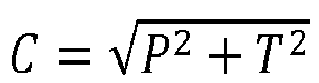
    The lightness L remains unchanged relative to CIELab. The resulting color space is referred to as LCh. For the P and T channels of the IPT color space, identical calculations may be performed, i.e. C = P 2 + T 2
    Figure imgb0003
    and h = tan 1 T P .
    Figure imgb0004
    The lightness I remains unchanged relative to the IPT space. The resulting color space is then referred to as ICH.
  • A commonly used correlate of visual experience is that of saturation. In either cylindrical color space, saturation is often defined as chroma divided by lightness : in LCh, saturation s would therefore be s = C L ,
    Figure imgb0005
    as in IPT, saturation s would therefore be : s(C,I) = C/I. In embodiments described below, nonlinear definitions of the saturation with respect to chroma and lightness will be used instead.
  • As both CIELab and IPT can be defined as transformations from the XYZ color space, it is assumed known how conversions from any RGB color space to CIELab and IPT may be performed.
  • Mapping colors in a color gamut:
  • Any given display device can be characterized in terms of its color gamut and dynamic range. The color content that may be received by such a device may have a different color gamut and a different dynamic range. If the display device has a wider gamut than this color content, it may be advantageous to expand color values representing colors of the content to better match its color gamut, thereby enhancing and representing colors of the content such that full advantage of the color gamut capabilities of the display device is obtained. Similarly, if the peak luminance of the display device exceeds that of the content, then the dynamic luminance range of the content may be expanded to match that of the display. All such adjustments should be carried out such that no colors of the content are mapped outside the display's color gamut.
  • Note that a color space (as discussed in the previous paragraph) is no more than a coordinate system, whereas a color gamut describes a boundary within such a coordinate system.
  • A current trend is toward the diversification of display capabilities. Professional content may be graded to a certain specification of color gamut and dynamic range. Some display devices will have a higher specification while others may be lower. At the same time, display devices may receive color content not specifically graded to match its capabilities. In such cases, a color management system is required that can make the adjustments.
  • Partial solutions to a complete color management system exist, and may be combined to form a system that includes tone mapping, inverse tone mapping, chroma management as well as gamut boundary management. However, by stringing together such partial solutions, the complexity of the combined solutions may be unnecessarily high, and may be visually sub-optimal.
  • In particular, existing ITMO solutions focus on (perceptually) reproducing the appearance of the original scene and rely on strict assumptions about the content. In particular, they focus on the expansion of the luminance channel of an LDR content, taking into account the maximum luminance that is reproducible by the display device, i.e. its peak luminance. In complement to an expansion on the luminance channel of a LDR content, some state-of-art iTMO algorithms perform chroma correction on the chromatic channels of this content in the corresponding color space (e.g., YCbCr for television content). This chroma correction is generally designed to keep the visual aspects of the LDR content (e.g., saturation), without any control with regard to the actual chromatic boundaries of the color gamut of the display device, i.e. of the target color gamut. It means that iTMO algorithms may adapt a color content with respect to the luminance boundaries of a target color gamut, without any regard to the chromatic ones. This in return results in out-of-gamut chromatic content that is either clipped by the display device when the content is displayed, or should be mapped into the target gamut in a complementary mapping step. Note that such a target gamut can be that of a hypothetical display device, for instance the output container color space defined by the standard BT.2020.
  • Summary of invention
  • An aim of the invention is to process simultaneously the luminance channel and the chromatic channels of a color content, instead of processing these channels separately as in the prior art. An aim of the invention is also to perform this process along a mapping curve which is different from a straight line, to mean a non-linear relationship between luminance or lightness and chroma. Such a simultaneous process will advantageously enable any iTMO algorithm to increase the dynamic range of a color content while keeping better the visual appearance of the color content.
  • Advantageously, it is also proposed to implement this process using not only an inverse tone-mapping algorithm along this mapping curve, and by also a tone-mapping algorithm along the same mapping curve, this tone-mapping algorithm being designed to bring any out-of-gamut inverse-tone mapped colors back to the output color gamut without changing significantly in-gamut inverse-tone mapped colors, notably those which are located far away from the boundary of his output gamut.
  • Advantageously, it is also proposed to limit the complexity of the combined solutions of the prior art.
  • For these purposes, the subject of the invention is a method of color gamut mapping input colors of an input LDR content into output colors forming an output HDR content, from an input color gamut towards an output color gamut in a mapping color space that can be partitioned into 2D constant-hue slices having axes for lightness or luminance and chroma, said color gamut mapping method comprising, for each input color: - expanding lightness or luminance and chroma of said input color in the constant-hue slice of said input color and along a mapping curve g (C,I) = 0 defining a relationship between lightness I or luminance and chroma C, where said expanding comprises applying an inverse tone mapping algorithm to lightness or luminance and results in an expanded color, wherein said mapping curve is different from a straight line in said constant-hue slice.
  • The input and output color gamut can be linked to an image device or can be linked to a color space container as that defined in a standard. Those gamuts or color space containers can be described in a manner known per se by a descriptor.
  • Preferably, said relationship between lightness I and chroma C is defined by the following equation: C = kp I ,
    Figure imgb0006
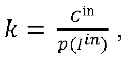
    where p(I) is a monotonically non-linearly increasing saturation compensation function defined such that that p(0) = 0, and where k is a scalar defined such that k = C in p I in ,
    Figure imgb0007
    where I in and C in are respectively the lightness and the chroma of said input color.
  • In a first variant, said saturation compensation function is defined by p (I) = Iq , where q is a saturation compensation exponent which is different from zero and different from 1. Preferably, said saturation compensation exponent q equal or superior to 1.5, or is equal or inferior to 0.5.
  • In a second variant, said relationship between lightness I and chroma C is defined by the following equation : C = a I p I + k ,
    Figure imgb0008
    where p(I) is a monotonically non-linearly increasing saturation compensation function defined such that that p(0) = 0, where a(I) is defined as a correlate of chroma in a color appearance model (CAM), and where k is a scalar defined such that k' = C in - a(Iin )p(Iin ), where I in and C in are respectively the lightness and the chroma of said input color.
  • Preferably, said expanding further comprises applying a tone mapping algorithm to luminance or lightness of said expanded color along said mapping curve, resulting in an output color forming said output content, wherein said tone mapping algorithm is designed to bring the expanded color inside the output color gamut if said expanded color is located out of said output color gamut. Preferably, said tone mapping algorithm is further designed to keep as unchanged as possible said expanded color if said expanded color is located inside the output color gamut. Preferably, said tone mapping algorithm is further designed to obtain a first linear compression of luminance or lightness for dark and mid-tone lightness levels that are inferior to a compression threshold I thresh and a second non-linear compression of luminance for high lightness levels that are superior to said compression threshold I thresh, wherein said second linear compression is higher than first linear compression. Preferably, said compression threshold I thresh is inferior but close to the luminance or lightness I gamut out
    Figure imgb0009
    of a color defined as the intersection of said mapping curve g(C,I) = 0 with said output color gamut.
  • A subject of the invention is also an image processing device comprising at least one processor configured to implement the above mapping method.
  • A subject of the invention is also an electronic device incorporating this image processing device, such as a TV set; a mobile device; a communication device; a game device; a tablet (or tablet computer) or a smartphone; a laptop; a camera; an encoding chip; a server.
  • A subject of the invention is also a non-transitory storage medium carrying instructions of program code for executing steps of the mapping method above, when said program is executed on a computing device.
  • Brief description of drawings
  • The invention will be more clearly understood on reading the description which follows, given by way of non-limiting example and with reference to the appended figure 1 describing a step (ii) of a main embodiment of the method of color gamut mapping according to the invention.
  • Description of embodiments
  • The functions of the various elements shown in the figure may be provided through the use of dedicated hardware as well as hardware capable of executing software in association with appropriate software. These functions may be substantially represented in computer readable media and so executed by a computer or processor, whether or not such computer or processor is explicitly shown. Explicit use of the term "processor" should not be construed to refer exclusively to hardware capable of executing software, and may implicitly include, without limitation, digital signal processor ("DSP") hardware, read-only memory ("ROM") for storing software, random access memory ("RAM"), and non-volatile storage.
  • A main general embodiment of the method of color gamut mapping will now be described in the following non-limiting context:
    1. 1. An input LDR color content with input colors, as for instance an image or a video sequence comprising a plurality of images.
    2. 2. A description of an input color gamut in which input colors of the input color content are included. Such an input color gamut can be linked to an image capture device (e.g., RGB of this capture device). Such an input color gamut can be an input color space container as that defined in the standard ITU-R Rec. BT 709, herein abbreviated as BT709.
    3. 3. A description of an output color gamut in which the output color content should be included. Such an output color gamut can be linked to an image display device (e.g., R'G'B' of this display device). Such an output color gamut can be an output space container as that defined in the standard ITU-R Rec. BT 2020, herein abbreviated as BT2020.
    4. 4. A description of a desired inverse tone-mapping operator (iTMO) f() and of a mapping color space in which this iTMO is defined. Any known iTMO adapted for luminance expansion can be used. Any tone mapping curve that is monotonically increasing may be inverted to serve as an inverse tone mapping curve forming an iTMO. Preferably, this mapping color space is a perceptual color space such as Lab or IPT.
    5. 5. A description of a desired tone-mapping operator (TMO)
      Figure imgb0010
      () applicable in the same mapping color space, defined to control the effect of the iTMO f() with respect to the boundaries of the output color gamut. More details are given below for this definition.
    6. 6. A relationship between luminance or lightness and chroma, expressing a desired perceptual aspect of the output color content. More details are given below. More details are given below for this relationship.
  • For the sake of simplicity, in this main non-limiting embodiment of color gamut mapping, no change of hue is applied. More specifically, the color mapping of each input color is performed in the constant-hue slice of this input color. In a variant, a step of mapping the hue of input colors can be implemented.
  • About item 6 above, changes in luminance levels as that created by inverse tone mapping process may create images that may appear too color saturated, or not color saturated enough. This is notably due to a quirk of the human visual system, which appears to interpret brighter scenes as being more saturated, even if the saturation encoded in the pixels is not affected. This is known as the Hunt effect. This means that, in processes of inverse tone mapping (as for any process involving a change in luminance), it is necessary to perform an additional adjustment to either saturation, or, equivalently, chroma, if no change of visual appearance of the content is desired.
  • To ensure that saturation of an inverse tone mapped content is perceived correctly, the inverse tone mapping should not be applied to luminance or lightness values only. In other words, along this mapping process, it is proposed not only to map the luminance or lightness, but also the chroma C of input colors according to a non-linear relationship between luminance or lightness and chroma which defines a mapping curve different from a straight line in the mapping color space.
  • In a first variant, this relationship is expressed according to: C = kp I ,
    Figure imgb0011
    where p(I) is a monotonically non-linearly increasing saturation compensation function defined such that that p(0) = 0, where k is a scalar which can be defined based on the input color to map, according to Equation No. 1a : k = C in p I in .
    Figure imgb0012
  • Preferably, the saturation compensation function p() is defined according to Equation No. 2: p I = I q ,
    Figure imgb0013
    where q is a saturation compensation exponent different from 1. For instance, q = 1.5, 2 or 0.5.
  • In a variant, the saturation compensation function p() is defined such that its second derivative with respect to I is negative.
  • Note that in case the saturation compensation function would have been linear (i.e. if q=1) and in case the saturation would have be defined as chroma divided by lightness, equation No. 1 would mean keeping the saturation constant.
  • In a second variant, this relationship between luminance or lightness and chroma is expressed according to: C = a I p I + k
    Figure imgb0014
    where p(I) is already defined above,
    where a(I) is defined as a correlate of chroma that can be found in any color appearance model (CAM).
    where k' is a scalar which can be defined based on the input color to map, according to Equation No. 3b : k' = C in - a(Iin )p(Iin ),
  • For instance, when using the CIECAM2, such a correlate of chroma a(I) can be defined according to: a I = t 0.29 10 1.64 0.29 n 0.73 I ,
    Figure imgb0015
    where t is a temporary constant quantity defined in the CIECAM2.
  • For instance, when using a Color Appearance Model defined by Reinhard, such a correlate of chroma a(I) can be defined according to: a I = 93 I IL max 1 + τ a m 2 + I IL max 1 + τ b m 2 10 3 + max 0 , I IL max 1 + τ d m 0.73 ,
    Figure imgb0016
    with am, bm, dm and τ being constants, and Lmax denoting the maximum output luminance of the display device linked to the output color gamut.
  • More generally, such a relationship between luminance or lightness and chroma can be expressed by: g C I = 0.
    Figure imgb0017
    Where g(,) is a non-linear function for at least one of the two variables C and I.
  • Again, in each constant-hue slice, such a non-linear function forms a curve that is different from a straight line. This curve will be named below "mapping curve". Each input color has its own mapping curve
  • About item 5 above concerning the definition of the tone-mapper operator
    Figure imgb0018
    (), let us states that:
    • the intersection of the mapping curve g(C,I) = 0 described above with the input color gamut defines a maximum lightness input I gamut in
      Figure imgb0019
      and
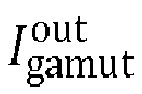
    • the intersection of this mapping curve g(C,I) = 0 with the output color gamut defines a maximum lightness output I gamut out .
      Figure imgb0020
  • When the application of the inverse tone mapped operator of item 3 above results in lightness values that are superior to I gamut out ,
    Figure imgb0021
    corresponding then to out-of-gamut expanded colors, it is desired to bring these out-of-gamut colors inside the output color gamut. The tone-mapper operator
    Figure imgb0022
    () of item 5 is designed to get this result when applied along the mapping curve g(C,I) = 0 to these out-of-gamut colors. This tone-mapper operator
    Figure imgb0023
    () is preferably designed not only to bring out-of-gamut colors inside the output color gamut, but also to keep as unchanged as possible expanded colors that located already inside the output gamut boundaries.
  • It means notably that it is preferred to design the tone-mapper operator such as to compress a small highest portion of the dynamic range, keeping most of it unchanged or only slightly changed. Preferably, this highest portion of the dynamic range corresponds to a part of the mapping curve with a lightness above a threshold output lightness I thresh, where I thresh is inferior but preferably close to I gamut out .
    Figure imgb0024
    A threshold color (C thresh,I thresh)ind can be defined on the mapping curve as the boundary between this highest portion and the lowest portion of the dynamic range.
  • More precisely, this tone-mapper operator can be defined in order to allow a slight linear compression of luminance for dark and mid-tone lightness levels inferior to I thresh but a higher and non-linear compression of luminance for high lightness levels superior to I thresh.
  • Having defined items 1 to 6 above, the main general embodiment of the method of color gamut mapping comprises :
    • (i) converting the input color content into the mapping color space,
    • (ii) performing luminance-chroma expansion of the converted input color content in the constant-hue slice of each input color along non-straight mapping curves g(C,I) = 0 (therefore meeting conditions of item 6 above) and inside the output color gamut (see item 3 above), by applying the iTMO of item 4 above and the TMO of item 5 above to its luminance channel,
    • (iii) converting the expanded content of step (ii) into the output color space.
  • The main general embodiment of this method is detailed below along these steps (i) to (iii).
  • (i) Conversion into a mapping color space:
  • Using any well-known conversion method, the input LDR color content is converted into the device independent XYZ color space, from there to the LMS color space (equation No.8 below), from there to the IPT color space (equation No.6 below), and, from there, to the cylindrical IPT (i.e. ICH) color space (equation No.5 below), as follows: { I = I C = P 2 + T 2 2 h = tan 1 T P
    Figure imgb0025
    I P T = W 1 L M S , with W 1 = 0.4000 0.4000 0.2000 4.4550 4.8510 0.3960 0.8056 0.3572 1.1628
    Figure imgb0026
    C = { C 0.43 if C 0 C 0.43 otherwise
    Figure imgb0027
    L M S = W 2 X Y Z , with W 2 = 0.4002 0.7075 0.0807 0.2280 1.1500 0.0612 0.0000 0.0000 0.9184
    Figure imgb0028
    where in Equation No. 7, C ∈ {L, M, S} and C' ∈ {L',M',S'} are calculated correspondingly. In Equation No. 1 , I stands for lightness, C for chroma and h for hue.
  • Similarly, the description of the input color gamut is converted into the mapping cylindrical color space ICh, and the description of the output color gamut is converted into the mapping cylindrical color space ICh.
  • Note that the mapping color space is three dimensional, and therefore so are the gamut boundaries. As the color mapping of each input color is performed in the constant-hue slice of this input color, these gamut boundaries can be represented in this constant-hue slice as a 2D lightness-chroma gamut curve.
  • (ii) Performing luminance-chroma expansion:
  • This step (ii) is illustrated on figure 1.
  • As the input color content and the gamut boundaries are now converted into the mapping color space, luminance-chroma expansion can be now performed, in which the converted lightness Iin and the converted chroma Cin of a color of the converted input color content are mapped respectively into an output lightness I t ind
    Figure imgb0029
    and an output chroma C t ind
    Figure imgb0030
    of an output color content such as the resulting mapped color is inside the output color gamut.
  • a) Mapping along the achromatic channel:
  • Conventional iTMO algorithms are typically designed to expand the luminance channel J of a color content as part of an inverse tone mapping process. Such an iTMO algorithm may be applied to the input converted content in order to expand the achromatic channel of the content. Denoting this achromatic channel by J, such an iTMO algorithm is designed to expand the range 0 J max in
    Figure imgb0031
    of the input color content to a range 0 J max out
    Figure imgb0032
    of the output color content. Here, the iTMO algorithm is denoted by a function J out = f (J in) that is a one dimensional function acting solely on the achromatic channel.
  • As, in the ICH mapping color space, the achromatic channel is not luminance but lightness (where lightness can be understood as a non-linear transform of luminance), the input J of the iTMO algorithm is temporarily converted forth and back using Equation No. 9 and Equation No. 10 to the lightness channel I using a conversion function denoted by £ : J = £ I = I 2.4 ,
    Figure imgb0033
    and: £ 1 J = J 1 / 2.4
    Figure imgb0034
  • The iTMO algorithm f(J) could therefore be applied on the lightness axis I of the mapping color space as follows: I out = £ 1 f £ I in
    Figure imgb0035
  • Applying the iTMO algorithm f() corresponds to a mapping of only lightness I. However, such a mapping would likely not produce chroma values that match visual expectation. In other words, the saturation of the lightness-mapped content will appear visually too low, notably due to the Hunt effect (quoted above).
  • b) Simultaneously mapping chroma along non-straight mapping curves g( C, I)= 0 :
  • While applying the iTMO algorithm f(), the non-linear relationship between lightness and chroma according to item 6 above is kept, resulting in an expansion of chroma Cin into a Cout .
  • When using the non-linear relationship between luminance or lightness and chroma as defined in its first variant above in equation No. 1, the chroma Cin is mapped into a chroma Cout according to : C out = C in p I out p I in
    Figure imgb0036
  • Using equation No. 2 defining p(I) and Equation No. 11 above, we have: C out = C in I in q £ 1 f £ I in q
    Figure imgb0037
    where q is the saturation compensation exponent defined above.
  • Note that if q=1, we would have had : C out = C in I out I in
    Figure imgb0038
  • Note that, if a linear relationship between lightness and chroma (i.e. q=1) would be used instead of a non-linear one C out = C in I out I in ,
    Figure imgb0039
    and/or if saturation would be defined as the ratio of chroma and lightness, the visual quality of the mapped colors would have been better than those that can be obtained by mapping luminance or lightness only. But, such a definition of saturation is approximate in itself. A non-linear relationship between chroma and lightness actually produce a visually better result. That is why it is preferred to have the saturation compensation exponent q different from 1. Preferred values are for instance, q = 1.5, 2 or 0.5.
  • When using the non-linear relationship between luminance or lightness and chroma as defined in its second variant above in equation No. 3, it is proposed to map the chroma Cin into a chroma Cout according to: C out = C in + a I out p I out a I in p I in
    Figure imgb0040
  • Using equation No. 2 defining p(I) and Equation No. 11 above, we have then C out = C in + a £ 1 f £ I in £ 1 f £ I in q a I in I in q
    Figure imgb0041
  • Preferably, the saturation compensation exponent q is inferior to 1. In this situation, the second derivative with respect to I of the saturation compensation function p() is negative. For instance, q = 0.5.
  • c) Mapping with respect of the gamut boundaries:
  • A third condition for the mapping of colors of the converted input content is that the resulting mapped colors should be located inside the converted output color gamut, as described according to item 3 above, this description being converted in sub-step a) above in the mapping color space. As a matter of fact, the expanded or mapped colors (C out,I out) resulting from steps (ii)-a) and (ii)-b) above that have a lightness superior to the maximum lightness output I gamut out
    Figure imgb0042
    are then located out the output color gamut.
  • To obtain the third condition above, it is proposed to apply along the same mapping curve g(C,I) = 0 the tone-mapping operator of item 4 to the expanded colors resulting from steps (ii)-b) above.
  • Applying this tone-mapper operator to the lightness channel of the lightness-mapped colors obtained from steps (ii)-a) and (ii)-b) will then give C t ind
    Figure imgb0043
    Figure imgb0044
  • The corresponding chroma C t ind
    Figure imgb0045
    is obtained by applying the equation of the mapping curve: g C t ind I t ind = 0
    Figure imgb0046
    C t ind I t ind
    Figure imgb0047
    cuppled with the corresponding hue is the final mapped output color. As the tone-mapper operator
    Figure imgb0048
    () is designed to bring out-of-gamut colors inside the output color gamut, the resulting colors C t ind I t ind
    Figure imgb0049
    are all located inside the output color gamut. As the tone-mapper operator
    Figure imgb0050
    () is designed to keep as unchanged as possible colors that were already located inside the output gamut boundaries, the effect of expansion of luminance or lightness provided by the inverse tone mapping algorithm is kept.
  • (iii) converting the expanded content of step (ii) into the output color space
  • The gamut mapped results of the previous step (ii) are finally converted from the mapping color space to the output color space. Assuming that the transformations between the device independent XYZ color space and the output device color space are known through the third input of the framework (item 3 above), the results are transformed back to the device independent XYZ color space. For the example of ICH being the mapping color space, this conversion uses for instance the following equations 5a to 8a, similar respectively to equations 5 to 8 above: X Y Z = W 3 L M S , W 3 = 1.8502 1.1383 0.2384 0.3668 0.6439 0.0107 0.0000 0.0000 1.0889
    Figure imgb0051
    C = { C 0.43 if C 0 C 0.43 else
    Figure imgb0052
    L M S = W 4 I P T , W 4 = 1.0000 0.0976 0.2052 1.0000 1.1139 0.1332 1.0000 0.0326 0.6769
    Figure imgb0053
    { I = I P = C cos h T = C sin h
    Figure imgb0054
    where in Equation No. 7b, C ∈ {L, M, S} and C' ∈ {L',M',S'}.
  • At the end of this color gamut mapping process, an HDR output color content is obtained.
  • The above method of color gamut mapping can be implemented in any image processing device using at least one processor configured to implement this method. Such an image processing device can be incorporated in an electronic device, such as a TV set; a mobile device ; a communication device ; a game device ; a tablet (or tablet computer) or a smartphone ; a laptop ; a camera ; an encoding chip ; a server.
  • It is to be understood that this method may be implemented in various forms of hardware, software, firmware, special purpose processors, or combinations thereof. This method may be notably implemented as a combination of hardware and software. Moreover, the software may be implemented as an application program tangibly embodied on a program storage unit. The application program may be uploaded to, and executed by, an image processing unit comprising any suitable architecture. Preferably, this unit is implemented on a computer platform having hardware such as one or more central processing units ("CPU"), a random access memory ("RAM"), and input/output ("I/O") interfaces. The computer platform may also include an operating system and microinstruction code. The various processes and functions described herein may be either part of the microinstruction code or part of the application program, or any combination thereof, which may be executed by a CPU. In addition, various other peripheral units may be connected to the computer platform such as an additional data storage unit and an image device, such as an image display device or an image capture device.
  • All embodiments and examples of the present invention are intended to encompass both structural and functional equivalents thereof. Additionally, it is intended that such equivalents include both currently known equivalents as well as equivalents developed in the future, i.e., any elements developed that perform the same function, regardless of structure.

Claims (13)

  1. Method of color gamut mapping input colors of an input LDR content into output colors forming an output HDR content, from an input color gamut towards an output color gamut in a mapping color space that can be partitioned into 2D constant-hue slices having axes for lightness or luminance and chroma, said color gamut mapping method comprising, for each input color:
    - expanding lightness or luminance and chroma of said input color in the constant-hue slice of said input color and along a mapping curve g(C,I) = 0 defining a relationship between lightness I or luminance and chroma C, where said expanding comprises applying an inverse tone mapping algorithm to lightness or luminance and results in an expanded color,
    wherein said mapping curve is different from a straight line in said constant-hue slice.
  2. Method of color gamut mapping according to claim 1 wherein said relationship between lightness I and chroma C is defined by the following equation: C = kp I ,
    Figure imgb0055
    where p(I) is a monotonically non-linearly increasing saturation compensation function defined such that that p(0) = 0, and where k is a scalar defined such that k = C in p I in ,
    Figure imgb0056
    where I in and C in are respectively the lightness and the chroma of said input color.
  3. Method of color gamut mapping according to claim 2 wherein said saturation compensation function is defined by p(I) = Iq , where q is a saturation compensation exponent which is different from zero and different from 1.
  4. Method of color gamut mapping according to claim 3 wherein said saturation compensation exponent q equal or superior to 1.5.
  5. Method of color gamut mapping according to claim 3 wherein said saturation compensation exponent q is equal or inferior to 0.5.
  6. Method of color gamut mapping according to claim 2 wherein said relationship between lightness I and chroma C is defined by the following equation: C = a I p I + k ,
    Figure imgb0057
    where p(I) is a monotonically non-linearly increasing saturation compensation function defined such that that p(0) = 0, where a(I) is defined as a correlate of chroma in a color appearance model (CAM), and where k is a scalar defined such that k' = C in - a(Iin)p(I in ), where I in and C in are respectively the lightness and the chroma of said input color.
  7. Method of color gamut mapping according to any one of claims 1 to 6 wherein said expanding further comprises applying a tone mapping algorithm to luminance or lightness of said expanded color along said mapping curve, resulting in an output color forming said output content, wherein said tone mapping algorithm is designed to bring the expanded color inside the output color gamut if said expanded color is located out of said output color gamut.
  8. Method of color gamut mapping according to claim 7, wherein said tone mapping algorithm is further designed to keep as unchanged as possible said expanded color if said expanded color is located inside the output color gamut.
  9. Method of color gamut mapping according to claim 7 or 8 wherein said tone mapping algorithm is further designed to obtain a first linear compression of luminance or lightness for dark and mid-tone lightness levels that are inferior to a compression threshold I thresh and a second non-linear compression of luminance for high lightness levels that are superior to said compression threshold I thresh, wherein said second linear compression is higher than first linear compression.
  10. Method of color gamut mapping according to claim 9 wherein said compression threshold I thresh is inferior but close to the luminance or lightness I gamut out
    Figure imgb0058
    of a color defined as the intersection of said mapping curve g(C,I) = 0 with said output color gamut.
  11. Image processing device comprising at least one processor configured to implement the method according to any one of claims 1 to 10.
  12. Electronic device incorporating the image processing device of claim 11.
  13. Non-transitory storage medium carrying instructions of program code for executing steps of the method according to one of claims 1 to 10 when said program is executed on a computing device.
EP16306735.8A 2016-12-20 2016-12-20 Method of color gamut mapping input colors of an input ldr content into output colors forming an output hdr content Withdrawn EP3340165A1 (en)

Priority Applications (2)

Application Number Priority Date Filing Date Title
EP16306735.8A EP3340165A1 (en) 2016-12-20 2016-12-20 Method of color gamut mapping input colors of an input ldr content into output colors forming an output hdr content
PCT/EP2017/082559 WO2018114509A1 (en) 2016-12-20 2017-12-13 Method of color gamut mapping input colors of an input ldr content into output colors forming an output hdr content

Applications Claiming Priority (1)

Application Number Priority Date Filing Date Title
EP16306735.8A EP3340165A1 (en) 2016-12-20 2016-12-20 Method of color gamut mapping input colors of an input ldr content into output colors forming an output hdr content

Publications (1)

Publication Number Publication Date
EP3340165A1 true EP3340165A1 (en) 2018-06-27

Family

ID=57755123

Family Applications (1)

Application Number Title Priority Date Filing Date
EP16306735.8A Withdrawn EP3340165A1 (en) 2016-12-20 2016-12-20 Method of color gamut mapping input colors of an input ldr content into output colors forming an output hdr content

Country Status (2)

Country Link
EP (1) EP3340165A1 (en)
WO (1) WO2018114509A1 (en)

Cited By (3)

* Cited by examiner, † Cited by third party
Publication number Priority date Publication date Assignee Title
CN110971841A (en) * 2019-12-09 2020-04-07 Oppo广东移动通信有限公司 Image processing method, device, storage medium and electronic device
KR20200065458A (en) * 2018-11-30 2020-06-09 고려대학교 산학협력단 Device and method for inverse tone mapping using a single low dynamic range image, recording medium for performing the method
US11910025B1 (en) 2015-08-04 2024-02-20 Dolby Laboratories Licensing Corporation Signal reshaping for high dynamic range signals

Citations (5)

* Cited by examiner, † Cited by third party
Publication number Priority date Publication date Assignee Title
EP0961488A2 (en) * 1998-05-28 1999-12-01 Sony Corporation Gamut mapping method and apparatus
US20080043260A1 (en) * 2006-08-21 2008-02-21 Texas Instruments Incorporated Color mapping techniques for color imaging devices
US20090154798A1 (en) * 2007-12-13 2009-06-18 Sony Corporation Information processing device and method, program, and information processing system
US20100020242A1 (en) * 2006-11-30 2010-01-28 Nxp, B.V. Device and method for processign color image data
US20160328830A1 (en) * 2013-12-27 2016-11-10 Thomson Licensing Method for inverse tone mapping of an image

Family Cites Families (2)

* Cited by examiner, † Cited by third party
Publication number Priority date Publication date Assignee Title
JP2010511314A (en) * 2006-11-23 2010-04-08 コーニンクレッカ フィリップス エレクトロニクス エヌ ヴィ Color gamut fit
WO2016192937A1 (en) 2015-05-29 2016-12-08 Thomson Licensing Methods, apparatus, and systems for hdr tone mapping operator

Patent Citations (5)

* Cited by examiner, † Cited by third party
Publication number Priority date Publication date Assignee Title
EP0961488A2 (en) * 1998-05-28 1999-12-01 Sony Corporation Gamut mapping method and apparatus
US20080043260A1 (en) * 2006-08-21 2008-02-21 Texas Instruments Incorporated Color mapping techniques for color imaging devices
US20100020242A1 (en) * 2006-11-30 2010-01-28 Nxp, B.V. Device and method for processign color image data
US20090154798A1 (en) * 2007-12-13 2009-06-18 Sony Corporation Information processing device and method, program, and information processing system
US20160328830A1 (en) * 2013-12-27 2016-11-10 Thomson Licensing Method for inverse tone mapping of an image

Non-Patent Citations (1)

* Cited by examiner, † Cited by third party
Title
MANTIUK R ET AL: "Color correction for tone mapping", COMPUTER GRAPHICS FORUM, WILEY-BLACKWELL PUBLISHING LTD, GB, vol. 28, no. 2, 1 April 2009 (2009-04-01), pages 193 - 202, XP002596979, ISSN: 0167-7055, DOI: 10.1111/J.1467-8659.2009.01358.X *

Cited By (13)

* Cited by examiner, † Cited by third party
Publication number Priority date Publication date Assignee Title
US12028555B2 (en) 2015-08-04 2024-07-02 Dolby Laboratories Licensing Corporation Signal reshaping for high dynamic range signals
US11910025B1 (en) 2015-08-04 2024-02-20 Dolby Laboratories Licensing Corporation Signal reshaping for high dynamic range signals
US11924477B2 (en) 2015-08-04 2024-03-05 Dolby Laboratories Licensing Corporation Signal reshaping for high dynamic range signals
US11979615B1 (en) * 2015-08-04 2024-05-07 Dolby Laboratories Licensing Corporation Signal reshaping for high dynamic range signals
US12041275B1 (en) 2015-08-04 2024-07-16 Dolby Laboratories Licensing Corporation Signal reshaping for high dynamic range signals
US12120357B2 (en) 2015-08-04 2024-10-15 Dolby Laboratories Licensing Corporation Signal reshaping for high dynamic range signals
US12120358B2 (en) 2015-08-04 2024-10-15 Dolby Laboratories Licensing Corporation Signal reshaping for high dynamic range signals
US12167048B2 (en) 2015-08-04 2024-12-10 Dolby Laboratories Licensing Corporation Signal reshaping for high dynamic range signals
US12200271B1 (en) 2015-08-04 2025-01-14 Dolby Laboratories Licensing Corporation Signal reshaping for high dynamic range signals
US12621501B2 (en) 2015-08-04 2026-05-05 Dolby Laboratories Licensing Corporation Signal reshaping for high dynamic range signals
KR20200065458A (en) * 2018-11-30 2020-06-09 고려대학교 산학협력단 Device and method for inverse tone mapping using a single low dynamic range image, recording medium for performing the method
CN110971841B (en) * 2019-12-09 2022-07-15 Oppo广东移动通信有限公司 Image processing method, device, storage medium and electronic device
CN110971841A (en) * 2019-12-09 2020-04-07 Oppo广东移动通信有限公司 Image processing method, device, storage medium and electronic device

Also Published As

Publication number Publication date
WO2018114509A1 (en) 2018-06-28

Similar Documents

Publication Publication Date Title
US10535125B2 (en) Dynamic global tone mapping with integrated 3D color look-up table
US9300938B2 (en) Systems, apparatus and methods for mapping between video ranges of image data and display
EP3205082B1 (en) Saturation processing specification for dynamic range mappings
US10937135B2 (en) Saturation processing specification for dynamic range mappings
EP2887636B1 (en) Method of mapping source colors from a source color gamut into a target color gamut
EP2120448A1 (en) Method of processing of a compressed image into a gamut mapped image using spatial frequency analysis
US10169886B2 (en) Method of mapping source colors of an image into a target color gamut of a target color device in two mapping steps
JP2018510574A (en) Display management for high dynamic range video
US9961236B2 (en) 3D color mapping and tuning in an image processing pipeline
EP3087725B1 (en) Method of mapping source colors of images of a video content into the target color gamut of a target color device
CN115023729B (en) Methods and corresponding devices for image conversion
US11290696B2 (en) Hue changing color gamut mapping
US8064693B2 (en) Methods of and apparatus for adjusting colour saturation in an input image
CN116167950A (en) Image processing method, device, electronic equipment and storage medium
US11006152B2 (en) Method and apparatus for encoding/decoding a high dynamic range picture into a coded bitstream
WO2018114509A1 (en) Method of color gamut mapping input colors of an input ldr content into output colors forming an output hdr content
EP3255874A1 (en) Method of mapping source colors of an image using a lut having input colors outside a source color gamut
CN114556910B (en) Video signal processing method and device
WO2023241339A1 (en) Color cast correction method and apparatus, device, storage medium and program product
US11769464B2 (en) Image processing
EP3242481A1 (en) Method and apparatus for encoding/decoding a high dynamic range picture into a coded bitstream
EP3110125A1 (en) Color gamut mapping using compensated gamut boundary description
JP2025541221A (en) Image processing device and image processing method
CN121391691A (en) Tone mapping processing method, equipment and storage medium for image
CN121746269A (en) Image tone mapping processing method, device, electronic equipment and storage medium

Legal Events

Date Code Title Description
PUAI Public reference made under article 153(3) epc to a published international application that has entered the european phase

Free format text: ORIGINAL CODE: 0009012

AK Designated contracting states

Kind code of ref document: A1

Designated state(s): AL AT BE BG CH CY CZ DE DK EE ES FI FR GB GR HR HU IE IS IT LI LT LU LV MC MK MT NL NO PL PT RO RS SE SI SK SM TR

AX Request for extension of the european patent

Extension state: BA ME

STAA Information on the status of an ep patent application or granted ep patent

Free format text: STATUS: THE APPLICATION IS DEEMED TO BE WITHDRAWN

18D Application deemed to be withdrawn

Effective date: 20190103