EP3339879A1 - Positioning system and method thereof - Google Patents
Positioning system and method thereof Download PDFInfo
- Publication number
- EP3339879A1 EP3339879A1 EP17210648.6A EP17210648A EP3339879A1 EP 3339879 A1 EP3339879 A1 EP 3339879A1 EP 17210648 A EP17210648 A EP 17210648A EP 3339879 A1 EP3339879 A1 EP 3339879A1
- Authority
- EP
- European Patent Office
- Prior art keywords
- electronic apparatus
- ultrasound
- ultrasonic signal
- radiation
- sensor
- Prior art date
- Legal status (The legal status is an assumption and is not a legal conclusion. Google has not performed a legal analysis and makes no representation as to the accuracy of the status listed.)
- Granted
Links
Images





Classifications
-
- G—PHYSICS
- G01—MEASURING; TESTING
- G01S—RADIO DIRECTION-FINDING; RADIO NAVIGATION; DETERMINING DISTANCE OR VELOCITY BY USE OF RADIO WAVES; LOCATING OR PRESENCE-DETECTING BY USE OF THE REFLECTION OR RERADIATION OF RADIO WAVES; ANALOGOUS ARRANGEMENTS USING OTHER WAVES
- G01S5/00—Position-fixing by co-ordinating two or more direction or position line determinations; Position-fixing by co-ordinating two or more distance determinations
- G01S5/18—Position-fixing by co-ordinating two or more direction or position line determinations; Position-fixing by co-ordinating two or more distance determinations using ultrasonic, sonic or infrasonic waves
- G01S5/30—Determining absolute distances from a plurality of spaced points of known location
-
- G—PHYSICS
- G01—MEASURING; TESTING
- G01S—RADIO DIRECTION-FINDING; RADIO NAVIGATION; DETERMINING DISTANCE OR VELOCITY BY USE OF RADIO WAVES; LOCATING OR PRESENCE-DETECTING BY USE OF THE REFLECTION OR RERADIATION OF RADIO WAVES; ANALOGOUS ARRANGEMENTS USING OTHER WAVES
- G01S5/00—Position-fixing by co-ordinating two or more direction or position line determinations; Position-fixing by co-ordinating two or more distance determinations
- G01S5/18—Position-fixing by co-ordinating two or more direction or position line determinations; Position-fixing by co-ordinating two or more distance determinations using ultrasonic, sonic or infrasonic waves
- G01S5/20—Position of source determined by a plurality of spaced direction-finders
-
- G—PHYSICS
- G01—MEASURING; TESTING
- G01S—RADIO DIRECTION-FINDING; RADIO NAVIGATION; DETERMINING DISTANCE OR VELOCITY BY USE OF RADIO WAVES; LOCATING OR PRESENCE-DETECTING BY USE OF THE REFLECTION OR RERADIATION OF RADIO WAVES; ANALOGOUS ARRANGEMENTS USING OTHER WAVES
- G01S5/00—Position-fixing by co-ordinating two or more direction or position line determinations; Position-fixing by co-ordinating two or more distance determinations
- G01S5/18—Position-fixing by co-ordinating two or more direction or position line determinations; Position-fixing by co-ordinating two or more distance determinations using ultrasonic, sonic or infrasonic waves
- G01S5/26—Position of receiver fixed by co-ordinating a plurality of position lines defined by path-difference measurements
-
- G—PHYSICS
- G01—MEASURING; TESTING
- G01S—RADIO DIRECTION-FINDING; RADIO NAVIGATION; DETERMINING DISTANCE OR VELOCITY BY USE OF RADIO WAVES; LOCATING OR PRESENCE-DETECTING BY USE OF THE REFLECTION OR RERADIATION OF RADIO WAVES; ANALOGOUS ARRANGEMENTS USING OTHER WAVES
- G01S11/00—Systems for determining distance or velocity not using reflection or reradiation
- G01S11/14—Systems for determining distance or velocity not using reflection or reradiation using ultrasonic, sonic or infrasonic waves
-
- G—PHYSICS
- G01—MEASURING; TESTING
- G01S—RADIO DIRECTION-FINDING; RADIO NAVIGATION; DETERMINING DISTANCE OR VELOCITY BY USE OF RADIO WAVES; LOCATING OR PRESENCE-DETECTING BY USE OF THE REFLECTION OR RERADIATION OF RADIO WAVES; ANALOGOUS ARRANGEMENTS USING OTHER WAVES
- G01S11/00—Systems for determining distance or velocity not using reflection or reradiation
- G01S11/16—Systems for determining distance or velocity not using reflection or reradiation using difference in transit time between electrical and acoustic signals
-
- G—PHYSICS
- G01—MEASURING; TESTING
- G01S—RADIO DIRECTION-FINDING; RADIO NAVIGATION; DETERMINING DISTANCE OR VELOCITY BY USE OF RADIO WAVES; LOCATING OR PRESENCE-DETECTING BY USE OF THE REFLECTION OR RERADIATION OF RADIO WAVES; ANALOGOUS ARRANGEMENTS USING OTHER WAVES
- G01S5/00—Position-fixing by co-ordinating two or more direction or position line determinations; Position-fixing by co-ordinating two or more distance determinations
- G01S5/18—Position-fixing by co-ordinating two or more direction or position line determinations; Position-fixing by co-ordinating two or more distance determinations using ultrasonic, sonic or infrasonic waves
- G01S5/28—Position-fixing by co-ordinating two or more direction or position line determinations; Position-fixing by co-ordinating two or more distance determinations using ultrasonic, sonic or infrasonic waves by co-ordinating position lines of different shape, e.g. hyperbolic, circular, elliptical or radial
-
- G—PHYSICS
- G02—OPTICS
- G02B—OPTICAL ELEMENTS, SYSTEMS OR APPARATUS
- G02B27/00—Optical systems or apparatus not provided for by any of the groups G02B1/00 - G02B26/00, G02B30/00
- G02B27/01—Head-up displays
- G02B27/017—Head mounted
-
- G—PHYSICS
- G06—COMPUTING OR CALCULATING; COUNTING
- G06T—IMAGE DATA PROCESSING OR GENERATION, IN GENERAL
- G06T19/00—Manipulating three-dimensional [3D] models or images for computer graphics
- G06T19/003—Navigation within 3D models or images
Definitions
- the present application relates to a positioning system. More particularly, the present application relates to a positioning system for locating the relative positions of controllers.
- a virtual reality system has a head-mounted display (HMD), a positional tracking device and controllers.
- the positional tracking device is configured for tracking the position and orientation of the HMD and controllers.
- the positional tracking device has some limitations (e.g., because the controllers are blocked by the user's body or objects in the environment, the positional tracking device could't track the user's controllers).
- the positioning system includes a first electronic apparatus and a second electronic apparatus.
- the first electronic apparatus includes a light emitting unit, a plurality of ultrasound sensors and a processor.
- the light emitting unit is configured for emitting a radiation.
- the processor is coupled to the light emitting unit and the ultrasound sensors.
- the second electronic apparatus includes a first optical sensor and a first ultrasound emitter.
- the first optical sensor is configured for sensing the radiation sent from the first electronic apparatus.
- the first ultrasound emitter is configured for sending a first ultrasonic signal when the radiation is sensed by the first optical sensor.
- the ultrasound sensors are configured to sense the first ultrasonic signal
- the processor is configured to calculate a plurality of first time periods started from the radiation is emitted until the first ultrasonic signal is sensed by the ultrasound sensors, to calculate a plurality of first relative distances between the ultrasound sensors and the first ultrasound emitter, and to locate a relative position of the second electronic apparatus relative to the first electronic apparatus according to the first relative distances.
- the positioning system includes a first electronic apparatus and a second electronic apparatus.
- the first electronic apparatus includes an ultrasound emitter, an optical sensor and a processor.
- the ultrasound emitter is configured for sending an ultrasonic signal.
- the processor is coupled to the ultrasound emitter and the optical sensor.
- the second electronic apparatus includes a plurality of ultrasound sensors and a first light emitting unit.
- the ultrasound sensors are configured for sensing the ultrasonic signal sent from the first electronic apparatus.
- the first light emitting unit is configured for emitting a plurality of radiations.
- the optical sensor is configured to sense the radiations
- the processor is configured to calculate a plurality of first time periods started from the ultrasonic signal is sent until the radiations are sensed by the optical sensor, to determine a plurality of first relative distances between the ultrasound sensors of the second electronic apparatus and the ultrasound emitter, and to locate a relative position of the second electronic apparatus relative to the first electronic apparatus according to the first relative distances.
- the positioning method includes operations of: emitting a radiation from a first electronic apparatus to a second electronic apparatus and starting to accumulate a time count; sensing the radiation on the second electronic apparatus and sending a first ultrasonic signal from the second electronic apparatus to the first electronic apparatus; sensing the first ultrasonic signal by a plurality of ultrasound sensors on the first electronic apparatus and calculating a plurality of first time periods started from the radiation is emitted until the first ultrasonic signal is sensed by the ultrasound sensors; calculating a plurality of first relative distances between the ultrasound sensors and a first ultrasound emitter on the second electronic apparatus; and locating a relative position of the second electronic apparatus relative to the first electronic apparatus according to the first relative distances.
- the first electronic apparatus in the positioning system is capable of calculating the time periods started from the radiation is emitted until the ultrasonic signal is sensed by the ultrasound sensors, and acquiring the relative distances between the ultrasound sensors and the ultrasound emitter according to the time periods.
- the relative distance can be obtained according to the time count accumulated on the first electronic apparatus.
- the second electronic apparatus is not required to include a timer circuit with high preciseness.
- FIG. 1 is a functional block diagram illustrating a positioning system 100 according to an embodiment of the disclosure.
- the positioning system 100 includes a first electronic apparatus 110, a second electronic apparatus 130 and a third electronic apparatus 150.
- the first electronic apparatus 110 can be implemented by a head-mounted device (HMD).
- the second electronic apparatus 130 and the third electronic apparatus 150 can be implemented by controller devices communicated with the head-mounted device.
- HMD head-mounted device
- the first electronic apparatus 110 includes a light emitting unit 111, a processor 112 and a plurality of ultrasound sensors 113a, 113b and 113c.
- the processor 112 includes a timer 112a.
- the processor 112 is coupled to the light emitting unit 111 and the ultrasound sensors 113a, 113b and 113c.
- the second electronic apparatus 130 includes an optical sensor 131 and an ultrasound emitter 132.
- the optical sensor 131 is coupled to the ultrasound emitter 132.
- the third electronic apparatus 150 includes an optical sensor 151 and an ultrasound emitter 152.
- the optical sensor 151 is coupled to the ultrasound emitter 152.
- the processor 112 can be implemented by a graphics processor, a central processing unit, a control circuit and/or a graphics processing unit.
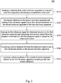
- FIG. 2 is a flow diagram illustrating a positioning method 200 according to an embodiment of this disclosure.
- the positioning method 200 can be utilized to calculate a relative position of the second electronic apparatus 130 relative to the first electronic apparatus 110 and another relative position of the third electronic apparatus 150 relative to the first electronic apparatus 110.
- the positioning method 200 firstly executes step S210 to emit a radiation from a first electronic apparatus 110 to a second electronic apparatus 130 and starting to accumulate a time count.
- a light emitting unit 111 of the first electronic apparatus 110 is configured for emitting a radiation and a processor 112 is configured for starting to accumulate a time count.
- the positioning method 200 executes step S220 to sense the radiation on the second electronic apparatus 130 and send a first ultrasonic signal fromthe ultrasound emitter 132 on the second electronic apparatus 130 to the first electronic apparatus 110.
- an optical sensor 131 of the second electronic apparatus 130 is configured for sensing the radiation sent from the first electronic apparatus 110 and an ultrasound emitter 132 of the second electronic apparatus 130 is configured for sending a first ultrasonic signal to the first electronic apparatus 110.
- the positioning method 200 executes step S230 to sense the first ultrasonic signal by ultrasound sensors 113a, 113b and 113c on the first electronic apparatus 110 and calculate time periods started from the radiation is emitted until the first ultrasonic signal is sensed by the ultrasound sensors113a, 113b and 113c.
- the ultrasound sensors 113a, 113b and 113c disposed at different positions on the first electronic apparatus 110. Therefore, the first ultrasonic signal is sensed by the ultrasound sensor 113a, the ultrasound sensor 113b and the ultrasound sensor 113c with time differences.
- FIG. 3 is a schematic diagram illustrating a relative position of the second electronic apparatus 130 according to an embodiment of the disclosure.
- a point P1 is represented by the ultrasound sensor 113a
- a point P2 is represented by the ultrasound sensor 113b
- a point P3 is represented by the ultrasound sensor 113c
- a point S is represented by the ultrasound emitter 132.
- the coordinate of the point P1 is (x1, y1, z1)
- the coordinate of the point P2 is (x2, y2, z2)
- the coordinate of the point P3 is (x3, y3, z3)
- the coordinate of the point S is (x, y, z).
- the time periods is corresponded to the point P1, P2 and P3.
- the distance d1 between the point P1 and the point S is utilized the time period and the sound velocity to obtain.
- the sound velocity can be assumed to be 340m/s. Therefore, the distance d2 and the distance d3 also could be calculated by the time periods and sound velocity.
- the positioning method 200 executes step S250 to locate a relative position of the second electronic apparatus 130 relative to the first electronic apparatus 110 according to the first relative distances.
- the ultrasound sensor 113a, 113b and 113c is disposed on the first electronic apparatus 110, the coordinate of the point P1, P2 and P3 is obtained.
- FIG. 4 is a schematic diagram illustrating a calculation of the time periods according to an embodiment of the disclosure.
- the light emitting unit 111 emits a radiation and the radiation is sensed by the optical sensor 131.
- the speed of radiation is approximately 3.00 ⁇ 10 8 m/s, therefore the transmission time T1 of the radiation approaches zero.
- the optical sensor 131 senses the radiation
- the optical sensor 131 triggers the ultrasound emitter 132 to send the first ultrasonic signal. It is assumed that a response time T2 (induced by a communication between the optical sensor 131 and the ultrasound emitter 132) since the radiation is sensed until the first ultrasonic signal is sent.
- the transmission time T3a, T3b and T3c of the first ultrasonic signal started from the ultrasound emitter 132 sent the first ultrasonic signal until the first ultrasonic signal is sensed by the ultrasound sensors 113a, 113b and 113c.
- the timer 112a will generate three accumulated time periods including a time period (T1+T2+T3a), another time period (T1+T2+T3b) and still another time period (T1+T2+T3c). Because the transmission time T1 approaches zero and the response time T2 is about a fixed time (about 20 ⁇ s), variations of the accumulated time periods will be dominated by the transmission times T3a, T3b and T3c, which are relatively longer than the transmission time T1 of the radiation.
- the first electronic apparatus 110 in the positioning system 100 is capable of calculating three time periods started from the radiation is emitted until the ultrasonic signal is sensed by the three ultrasound sensors 113a, 113b and 113c, and acquiring the relative distances between the ultrasound sensors 113a, 113b and 113c and the ultrasound emitter 132 according to the time periods.
- the relative distance can be obtained according to the time periods accumulated on the first electronic apparatus 110.
- the second electronic apparatus 130 is not required to include a timer circuit with high preciseness. Therefore, time synchronization between the first electronic apparatus 110 and the second electronic apparatus 130 is not necessary during the positioning procedure.
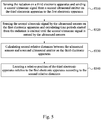
- FIG. 5 is a flow diagram illustrating an operating flow between first electronic apparatus 110 and third electronic apparatus 150 according to an embodiment of this disclosure.
- the positioning method 200 executes step S310 to sense the radiation on a third electronic apparatus 150 and send a second ultrasonic signal from the ultrasound emitter 152 on the third electronic apparatus 150 to the first electronic apparatus 110.
- the radiation is sensed by the second electronic apparatus 130 and the third electronic apparatus 150 separately, to execute steps S220-S250 and steps S310-S340.
- the first electronic apparatus 110 further includes a PWM circuit is coupled with the processor 112 and the light emitting unit 111.
- the PWM circuit is configured for adjusting a duty ratio of the radiation generated by the light emitting unit 111.
- the PWM circuit is set by a first duty ratio
- the radiation with the first duty ratio is utilized to trigger the ultrasound emitter 132 of the second electronic apparatus 130
- the PWM circuit is set by a second duty ratio
- the radiation with the second duty ratio is utilized to trigger the ultrasound emitter 152 of the third electronic apparatus 150.
- the first electronic apparatus 110 could control the second electronic apparatus 130 or the third electronic apparatus 150 to send the ultrasonic signal.
- the PWM circuit is configured to modulate the radiation in different duty ratios for triggering the second electronic apparatus 130 and the third electronic apparatus 150 individually.
- a manner to trigger different controllers is not limited to utilize the PWM circuit in aforesaid embodiment.
- the light emitting unit 111 could emit the different radiations in colors, frequencies, duty ratios or brightness to trigger the different controllers.
- FIG. 6 is a functional block diagram illustrating a positioning system 500 according to an embodiment of the disclosure.
- the positioning system 500 includes a first electronic apparatus 510, a second electronic apparatus 530 and a third electronic apparatus 550.
- the first electronic apparatus 510 can be implemented by a head-mounted device (HMD).
- the second electronic apparatus 530 and the third electronic apparatus 550 can be implemented by controller devices communicated with the head-mounted device.
- the first electronic apparatus 510 includes an ultrasound emitter 511, a processor 512 and an optical sensor 513.
- the processor 512 includes a timer 512a.
- the processor 512 is coupled to the ultrasound emitter 511 and the optical sensor 513.
- the second electronic apparatus 530 includes a light emitting unit 531 and a plurality of ultrasound sensors 532a, 532b and 532c.
- the light emitting unit 531 is coupled to the ultrasound sensors 532a, 532b and 532c.
- the third electronic apparatus 550 includes a light emitting unit 551 and a plurality of ultrasound sensors 552a, 552b and 552c.
- the light emitting unit 551 is coupled to the ultrasound sensors 552a, 552b and 552c.
- the processor 512 can be implemented by a processor, a central processing unit, a control circuit and/or a graphic processing unit.
- the ultrasound emitter 511 is configured for sending an ultrasonic signal to the second electronic apparatus 530 and the processor 512 stared to accumulate a time count.
- the ultrasound sensors 532a, 532b and 532c are configured for sensing the ultrasonic signal sent from the first electronic apparatus 510.
- the light emitting unit 531 is configured for emitting a plurality of radiations.
- the optical sensor 513 is configured to sense the radiations.
- the ultrasound sensors 532a, 532b and 532c disposed at different positions on the second electronic apparatus 530.
- the ultrasonic signal is sensed by the ultrasound sensors 532a, 532b and 532c with time differences. Therefore, the light emitting unit 531 is triggered to send one of the radiations when the ultrasound sensor 532a senses the ultrasonic signal, the light emitting unit 531 is triggered to send another one of the radiations when the ultrasound sensor 532b senses the ultrasonic signal, and the light emitting unit 531 is triggered to send another one of the radiations when the ultrasound sensor 532c senses the ultrasonic signal.
- the light emitting unit 531 is triggered three times respectively by the ultrasound sensor 532a, 532b and 532c.
- the timer 512a calculates three time periods started from the ultrasonic signal is sent from the first electronic apparatus 510 until the radiations are sensed on the first electronic apparatus 510.
- FIG. 7 is a schematic diagram illustrating a relative position of the second electronic apparatus 530 according to an embodiment of the disclosure.
- point P1 is represented by the ultrasound sensor 532a
- a point P2 is represented by the ultrasound sensor 532b
- a point P3 is represented by the ultrasound sensor 532c
- a point S is represented by the ultrasound emitter 511.
- the coordinate of the point P1 is (x1, y1, z1)
- the coordinate of the point P2 is (x2, y2, z2)
- the coordinate of the point P3 is (x3, y3, z3)
- the coordinate of the point S is (x, y, z).
- the time periods correspond to the point P1, P2 and P3.
- the ultrasound sensor 532a senses the ultrasonic signal from the ultrasound emitter 511
- the light emitting unit 531 is triggered to send one of the radiations to the optical sensor 513.
- the time period is corresponding to the point P1.
- the distance between the ultrasound emitter 511 and the ultrasound sensor 532a could be calculated by the time period and sound velocity (340m/s).
- the coordinate of the point S is obtained (the coordinate of the head-mounted device).
- the relative coordinate of the point P1, P2 and P3 of each other is obtained, because the ultrasound sensor 532a, 532b and 532c is disposed on the second electronic apparatus 530. Therefore the relative position of the second electronic apparatus 530 (x1, y1, z1) relative to the first electronic apparatus 510 could be calculated by Formula 2.
- the relative distance of ultrasound sensor 532b and 532c relative to ultrasound sensor 532a can be calculated through Formula 3.
- the structure and operating flow of the third electronic apparatus 550 is same as the second electronic apparatus 530 and not to be further discussed here. It is noticed that, the radiations emitted by the light emitting unit 551 are different from the radiations emitted by the light emitting unit 531 in colors, frequencies, duty ratios or brightness. Therefore, the first electronic apparatus 510 is able distinguish the radiations from the light emitting unit 531 and the light emitting unit 551 according to colors, frequencies, duty ratios or brightness of the radiations.
- the PWM circuit is configured to modulate the radiation in different duty ratios for triggering the optical sensor 513 of the first electronic apparatus 510.
- a manner to trigger optical sensor 513 is not limited to utilize the PWM circuit in aforesaid embodiment.
- the light emitting unit 531 and the light emitting unit 551 could emit the different radiations in colors, frequencies, duty ratios or brightness to trigger the different controllers.
- the first electronic apparatus 110 in the positioning system 500 is capable of calculating three time periods started from the ultrasonic signal is sent until the radiations is sensed by the optical sensor 513, and acquiring the relative distances between the ultrasound sensors 532a, 532b and 532c and the ultrasound emitter 511 according to the time periods.
- the relative distance can be obtained according to the time periods accumulated on the first electronic apparatus 510.
- the second electronic apparatus 530 and the third electronic apparatus 550 are not required to include a timer circuit with high preciseness. Therefore, time synchronization between the first electronic apparatus 510, the second electronic apparatus 530 and the third electronic apparatus 550 is not necessary during the positioning procedure.
Landscapes
- Physics & Mathematics (AREA)
- Engineering & Computer Science (AREA)
- General Physics & Mathematics (AREA)
- Radar, Positioning & Navigation (AREA)
- Remote Sensing (AREA)
- Software Systems (AREA)
- Optics & Photonics (AREA)
- Computer Graphics (AREA)
- Computer Hardware Design (AREA)
- General Engineering & Computer Science (AREA)
- Theoretical Computer Science (AREA)
- Measurement Of Velocity Or Position Using Acoustic Or Ultrasonic Waves (AREA)
- Length Measuring Devices Characterised By Use Of Acoustic Means (AREA)
Abstract
Description
- The present application relates to a positioning system. More particularly, the present application relates to a positioning system for locating the relative positions of controllers.
- In the current virtual reality (VR) environment, controller devices are commonly used to interact with VR scenes, such as game themes or VR contents. Usually, a virtual reality system has a head-mounted display (HMD), a positional tracking device and controllers. The positional tracking device is configured for tracking the position and orientation of the HMD and controllers. However, the positional tracking device has some limitations (e.g., because the controllers are blocked by the user's body or objects in the environment, the positional tracking device couldn't track the user's controllers).
- An aspect of the disclosure is to provide a positioning system. The positioning system includes a first electronic apparatus and a second electronic apparatus. The first electronic apparatus includes a light emitting unit, a plurality of ultrasound sensors and a processor. The light emitting unit is configured for emitting a radiation. The processor is coupled to the light emitting unit and the ultrasound sensors. The second electronic apparatus includes a first optical sensor and a first ultrasound emitter. The first optical sensor is configured for sensing the radiation sent from the first electronic apparatus. The first ultrasound emitter is configured for sending a first ultrasonic signal when the radiation is sensed by the first optical sensor. The ultrasound sensors are configured to sense the first ultrasonic signal, the processor is configured to calculate a plurality of first time periods started from the radiation is emitted until the first ultrasonic signal is sensed by the ultrasound sensors, to calculate a plurality of first relative distances between the ultrasound sensors and the first ultrasound emitter, and to locate a relative position of the second electronic apparatus relative to the first electronic apparatus according to the first relative distances.
- Another aspect of the disclosure is to provide a positioning system. The positioning system includes a first electronic apparatus and a second electronic apparatus. The first electronic apparatus includes an ultrasound emitter, an optical sensor and a processor. The ultrasound emitter is configured for sending an ultrasonic signal. The processor is coupled to the ultrasound emitter and the optical sensor. The second electronic apparatus includes a plurality of ultrasound sensors and a first light emitting unit. The ultrasound sensors are configured for sensing the ultrasonic signal sent from the first electronic apparatus. The first light emitting unit is configured for emitting a plurality of radiations. The optical sensor is configured to sense the radiations, the processor is configured to calculate a plurality of first time periods started from the ultrasonic signal is sent until the radiations are sensed by the optical sensor, to determine a plurality of first relative distances between the ultrasound sensors of the second electronic apparatus and the ultrasound emitter, and to locate a relative position of the second electronic apparatus relative to the first electronic apparatus according to the first relative distances.
- Another aspect of the disclosure is to provide a positioning method suitable for a positioning system including a first electronic apparatus and a second electronic apparatus. The positioning method includes operations of: emitting a radiation from a first electronic apparatus to a second electronic apparatus and starting to accumulate a time count; sensing the radiation on the second electronic apparatus and sending a first ultrasonic signal from the second electronic apparatus to the first electronic apparatus; sensing the first ultrasonic signal by a plurality of ultrasound sensors on the first electronic apparatus and calculating a plurality of first time periods started from the radiation is emitted until the first ultrasonic signal is sensed by the ultrasound sensors; calculating a plurality of first relative distances between the ultrasound sensors and a first ultrasound emitter on the second electronic apparatus; and locating a relative position of the second electronic apparatus relative to the first electronic apparatus according to the first relative distances.
- Based on aforesaid embodiments, the first electronic apparatus in the positioning system is capable of calculating the time periods started from the radiation is emitted until the ultrasonic signal is sensed by the ultrasound sensors, and acquiring the relative distances between the ultrasound sensors and the ultrasound emitter according to the time periods. In some embodiments, it is not necessary to synchronize clock signals between the first electronic apparatus and the second electronic apparatus. The relative distance can be obtained according to the time count accumulated on the first electronic apparatus. The second electronic apparatus is not required to include a timer circuit with high preciseness.
- Aspects of the present disclosure are best understood from the following detailed description when read with the accompanying figures. It is noted that, in accordance with the standard practice in the industry, various features are not drawn to scale. In fact, the dimensions of the various features may be arbitrarily increased or reduced for clarity of discussion.
-
FIG. 1 is a functional block diagram illustrating a positioning system according to an embodiment of the disclosure. -
FIG. 2 is a flow diagram illustrating a positioning method according to an embodiment of this disclosure. -
FIG. 3 is a schematic diagram illustrating a relative position of the second electronic apparatus according to an embodiment of the disclosure. -
FIG. 4 is a schematic diagram illustrating a calculation of the time periods according to an embodiment of the disclosure. -
FIG. 5 is a flow diagram illustrating an operating flow between first electronic apparatus and third electronic apparatus according to an embodiment of this disclosure. -
FIG. 6 is a functional block diagram illustrating a positioning system according to an embodiment of the disclosure. -
FIG. 7 is a schematic diagram illustrating a relative position of the secondelectronic apparatus 130 according to an embodiment of the disclosure. - The following disclosure provides many different embodiments, or examples, for implementing different features of the invention. Specific examples of components and arrangements are described below to simplify the present disclosure. These are, of course, merely examples and are not intended to be limiting. In addition, the present disclosure may repeat reference numerals and/or letters in the various examples. This repetition is for the purpose of simplicity and clarity and does not in itself dictate a relationship between the various embodiments and/or configurations discussed.
- Reference is made to
FIG. 1 , which is a functional block diagram illustrating apositioning system 100 according to an embodiment of the disclosure. As shown inFIG. 1 , thepositioning system 100 includes a firstelectronic apparatus 110, a secondelectronic apparatus 130 and a thirdelectronic apparatus 150. The firstelectronic apparatus 110 can be implemented by a head-mounted device (HMD). The secondelectronic apparatus 130 and the thirdelectronic apparatus 150 can be implemented by controller devices communicated with the head-mounted device. - The first
electronic apparatus 110 includes alight emitting unit 111, aprocessor 112 and a plurality ofultrasound sensors processor 112 includes atimer 112a. Theprocessor 112 is coupled to thelight emitting unit 111 and theultrasound sensors electronic apparatus 130 includes anoptical sensor 131 and anultrasound emitter 132. Theoptical sensor 131 is coupled to theultrasound emitter 132. The thirdelectronic apparatus 150 includes anoptical sensor 151 and anultrasound emitter 152. Theoptical sensor 151 is coupled to theultrasound emitter 152. Theprocessor 112 can be implemented by a graphics processor, a central processing unit, a control circuit and/or a graphics processing unit. - Reference is made to
FIG. 2 , which is a flow diagram illustrating apositioning method 200 according to an embodiment of this disclosure. In the embodiment, thepositioning method 200 can be utilized to calculate a relative position of the secondelectronic apparatus 130 relative to the firstelectronic apparatus 110 and another relative position of the thirdelectronic apparatus 150 relative to the firstelectronic apparatus 110. - Reference is made to
FIG. 1 andFIG. 2 . As the embodiment shown inFIG. 2 , thepositioning method 200 firstly executes step S210 to emit a radiation from a firstelectronic apparatus 110 to a secondelectronic apparatus 130 and starting to accumulate a time count. In the embodiment, alight emitting unit 111 of the firstelectronic apparatus 110 is configured for emitting a radiation and aprocessor 112 is configured for starting to accumulate a time count. - Afterward, the
positioning method 200 executes step S220 to sense the radiation on the secondelectronic apparatus 130 and send a first ultrasonic signal fromtheultrasound emitter 132 on the secondelectronic apparatus 130 to the firstelectronic apparatus 110. In the embodiment, anoptical sensor 131 of the secondelectronic apparatus 130 is configured for sensing the radiation sent from the firstelectronic apparatus 110 and anultrasound emitter 132 of the secondelectronic apparatus 130 is configured for sending a first ultrasonic signal to the firstelectronic apparatus 110. - Afterward, the
positioning method 200 executes step S230 to sense the first ultrasonic signal byultrasound sensors electronic apparatus 110 and calculate time periods started from the radiation is emitted until the first ultrasonic signal is sensed by the ultrasound sensors113a, 113b and 113c. In the embodiment, theultrasound sensors electronic apparatus 110. Therefore, the first ultrasonic signal is sensed by theultrasound sensor 113a, theultrasound sensor 113b and theultrasound sensor 113c with time differences. - Afterward, the
positioning method 200 executes step S240 to calculate relative distances between theultrasound sensors ultrasound emitter 132 on the secondelectronic apparatus 130. Reference is made toFIG. 3. FIG. 3 is a schematic diagram illustrating a relative position of the secondelectronic apparatus 130 according to an embodiment of the disclosure. As the example shown inFIG. 3 , a point P1 is represented by theultrasound sensor 113a, a point P2 is represented by theultrasound sensor 113b, a point P3 is represented by theultrasound sensor 113c and a point S is represented by theultrasound emitter 132. The coordinate of the point P1 is (x1, y1, z1), the coordinate of the point P2 is (x2, y2, z2), the coordinate of the point P3 is (x3, y3, z3) and the coordinate of the point S is (x, y, z). It is noticed that, the time periods is corresponded to the point P1, P2 and P3. Once the time period between the point P1 and the point S in step S230 is determined, the distance d1 between the point P1 and the point S is utilized the time period and the sound velocity to obtain. In this embodiment, the sound velocity can be assumed to be 340m/s. Therefore, the distance d2 and the distance d3 also could be calculated by the time periods and sound velocity. - Afterward, the
positioning method 200 executes step S250 to locate a relative position of the secondelectronic apparatus 130 relative to the firstelectronic apparatus 110 according to the first relative distances. As the example shown inFIG. 3 , because theultrasound sensor electronic apparatus 110, the coordinate of the point P1, P2 and P3 is obtained. The coordinate (x, y, z) of the point S could be calculated by Formula 1. Therefore, the coordinate of theultrasound emitter 132 of the secondelectronic apparatus 130 is obtained.
- Reference is made to
FIG. 4. FIG. 4 is a schematic diagram illustrating a calculation of the time periods according to an embodiment of the disclosure. As the example shown inFIG. 4 , thelight emitting unit 111 emits a radiation and the radiation is sensed by theoptical sensor 131. The speed of radiation is approximately 3.00×10⁸ m/s, therefore the transmission time T1 of the radiation approaches zero. When theoptical sensor 131 senses the radiation, theoptical sensor 131 triggers theultrasound emitter 132 to send the first ultrasonic signal. It is assumed that a response time T2 (induced by a communication between theoptical sensor 131 and the ultrasound emitter 132) since the radiation is sensed until the first ultrasonic signal is sent. The transmission time T3a, T3b and T3c of the first ultrasonic signal started from theultrasound emitter 132 sent the first ultrasonic signal until the first ultrasonic signal is sensed by theultrasound sensors timer 112a will generate three accumulated time periods including a time period (T1+T2+T3a), another time period (T1+T2+T3b) and still another time period (T1+T2+T3c). Because the transmission time T1 approaches zero and the response time T2 is about a fixed time (about 20 µs), variations of the accumulated time periods will be dominated by the transmission times T3a, T3b and T3c, which are relatively longer than the transmission time T1 of the radiation. - Based on aforesaid embodiments, the first
electronic apparatus 110 in thepositioning system 100 is capable of calculating three time periods started from the radiation is emitted until the ultrasonic signal is sensed by the threeultrasound sensors ultrasound sensors ultrasound emitter 132 according to the time periods. In some embodiments, it is not necessary to synchronize clock signals between the firstelectronic apparatus 110 and the secondelectronic apparatus 130. The relative distance can be obtained according to the time periods accumulated on the firstelectronic apparatus 110. The secondelectronic apparatus 130 is not required to include a timer circuit with high preciseness. Therefore, time synchronization between the firstelectronic apparatus 110 and the secondelectronic apparatus 130 is not necessary during the positioning procedure. - Reference is made to
FIG. 1 to FIG. 5 .FIG. 5 is a flow diagram illustrating an operating flow between firstelectronic apparatus 110 and thirdelectronic apparatus 150 according to an embodiment of this disclosure. After the Step S210, thepositioning method 200 executes step S310 to sense the radiation on a thirdelectronic apparatus 150 and send a second ultrasonic signal from theultrasound emitter 152 on the thirdelectronic apparatus 150 to the firstelectronic apparatus 110. In this embodiment, when thelight emitting unit 111 of the firstelectronic apparatus 110 is emitted a radiation, the radiation is sensed by the secondelectronic apparatus 130 and the thirdelectronic apparatus 150 separately, to execute steps S220-S250 and steps S310-S340. - Afterward, the operating flow of step S320-S340 can be understood from aforesaid embodiment demonstrating the example of step S230-S250, and not further discussed here. It is noticed that, the first
electronic apparatus 110 further includes a PWM circuit is coupled with theprocessor 112 and thelight emitting unit 111. The PWM circuit is configured for adjusting a duty ratio of the radiation generated by thelight emitting unit 111. When the PWM circuit is set by a first duty ratio, the radiation with the first duty ratio is utilized to trigger theultrasound emitter 132 of the secondelectronic apparatus 130; and when the PWM circuit is set by a second duty ratio, the radiation with the second duty ratio is utilized to trigger theultrasound emitter 152 of the thirdelectronic apparatus 150. Therefore, the firstelectronic apparatus 110 could control the secondelectronic apparatus 130 or the thirdelectronic apparatus 150 to send the ultrasonic signal. The PWM circuit is configured to modulate the radiation in different duty ratios for triggering the secondelectronic apparatus 130 and the thirdelectronic apparatus 150 individually. A manner to trigger different controllers is not limited to utilize the PWM circuit in aforesaid embodiment. In another embodiment, thelight emitting unit 111 could emit the different radiations in colors, frequencies, duty ratios or brightness to trigger the different controllers. - In another embodiment, reference is made to
FIG. 6. FIG. 6 is a functional block diagram illustrating apositioning system 500 according to an embodiment of the disclosure. Thepositioning system 500 includes a firstelectronic apparatus 510, a secondelectronic apparatus 530 and a thirdelectronic apparatus 550. The firstelectronic apparatus 510 can be implemented by a head-mounted device (HMD). The secondelectronic apparatus 530 and the thirdelectronic apparatus 550 can be implemented by controller devices communicated with the head-mounted device. - The first
electronic apparatus 510 includes anultrasound emitter 511, aprocessor 512 and anoptical sensor 513. Theprocessor 512 includes atimer 512a. Theprocessor 512 is coupled to theultrasound emitter 511 and theoptical sensor 513. The secondelectronic apparatus 530 includes alight emitting unit 531 and a plurality ofultrasound sensors light emitting unit 531 is coupled to theultrasound sensors electronic apparatus 550 includes alight emitting unit 551 and a plurality ofultrasound sensors light emitting unit 551 is coupled to theultrasound sensors processor 512 can be implemented by a processor, a central processing unit, a control circuit and/or a graphic processing unit. - Afterward, the
ultrasound emitter 511 is configured for sending an ultrasonic signal to the secondelectronic apparatus 530 and theprocessor 512 stared to accumulate a time count. Theultrasound sensors electronic apparatus 510. When theultrasound sensors light emitting unit 531 is configured for emitting a plurality of radiations. Theoptical sensor 513 is configured to sense the radiations. - Afterward, the
ultrasound sensors electronic apparatus 530. The ultrasonic signal is sensed by theultrasound sensors light emitting unit 531 is triggered to send one of the radiations when theultrasound sensor 532a senses the ultrasonic signal, thelight emitting unit 531 is triggered to send another one of the radiations when theultrasound sensor 532b senses the ultrasonic signal, and thelight emitting unit 531 is triggered to send another one of the radiations when theultrasound sensor 532c senses the ultrasonic signal. In this embodiment, thelight emitting unit 531 is triggered three times respectively by theultrasound sensor timer 512a calculates three time periods started from the ultrasonic signal is sent from the firstelectronic apparatus 510 until the radiations are sensed on the firstelectronic apparatus 510. - Reference is made to
FIG. 7. FIG. 7 is a schematic diagram illustrating a relative position of the secondelectronic apparatus 530 according to an embodiment of the disclosure. As the example shown inFIG. 7 , point P1 is represented by theultrasound sensor 532a, a point P2 is represented by theultrasound sensor 532b, a point P3 is represented by theultrasound sensor 532c and a point S is represented by theultrasound emitter 511. The coordinate of the point P1 is (x1, y1, z1), the coordinate of the point P2 is (x2, y2, z2), the coordinate of the point P3 is (x3, y3, z3) and the coordinate of the point S is (x, y, z). It is noticed that, the time periods correspond to the point P1, P2 and P3. For example, when theultrasound sensor 532a senses the ultrasonic signal from theultrasound emitter 511, thelight emitting unit 531 is triggered to send one of the radiations to theoptical sensor 513. The time period is corresponding to the point P1. The distance between theultrasound emitter 511 and theultrasound sensor 532a could be calculated by the time period and sound velocity (340m/s). - Afterward, as the example shown in
FIG. 7 , the coordinate of the point S is obtained (the coordinate of the head-mounted device). The relative coordinate of the point P1, P2 and P3 of each other is obtained, because theultrasound sensor electronic apparatus 530. Therefore the relative position of the second electronic apparatus 530 (x1, y1, z1) relative to the firstelectronic apparatus 510 could be calculated by Formula 2. The Formula 2 can be converted into another Formula 3 because the relative position of the point P1, P2 and P3 are already known (i.e., x2=x1+α, y2=y1+α, z2=z1+α, x3=x1+β, y3=y1+β and z3=z1+β, wherein α and β are constants). The relative distance ofultrasound sensor ultrasound sensor 532a can be calculated through Formula 3.

- In this embodiment, the structure and operating flow of the third
electronic apparatus 550 is same as the secondelectronic apparatus 530 and not to be further discussed here. It is noticed that, the radiations emitted by thelight emitting unit 551 are different from the radiations emitted by thelight emitting unit 531 in colors, frequencies, duty ratios or brightness. Therefore, the firstelectronic apparatus 510 is able distinguish the radiations from thelight emitting unit 531 and thelight emitting unit 551 according to colors, frequencies, duty ratios or brightness of the radiations. - The PWM circuit is configured to modulate the radiation in different duty ratios for triggering the
optical sensor 513 of the firstelectronic apparatus 510. A manner to triggeroptical sensor 513 is not limited to utilize the PWM circuit in aforesaid embodiment. In another embodiment, thelight emitting unit 531 and thelight emitting unit 551 could emit the different radiations in colors, frequencies, duty ratios or brightness to trigger the different controllers. - Based on aforesaid embodiments, the first
electronic apparatus 110 in thepositioning system 500 is capable of calculating three time periods started from the ultrasonic signal is sent until the radiations is sensed by theoptical sensor 513, and acquiring the relative distances between theultrasound sensors ultrasound emitter 511 according to the time periods. In some embodiments, it is not necessary to synchronize clock signals between the firstelectronic apparatus 510, the secondelectronic apparatus 530 and the thirdelectronic apparatus 550. The relative distance can be obtained according to the time periods accumulated on the firstelectronic apparatus 510. The secondelectronic apparatus 530 and the thirdelectronic apparatus 550 are not required to include a timer circuit with high preciseness. Therefore, time synchronization between the firstelectronic apparatus 510, the secondelectronic apparatus 530 and the thirdelectronic apparatus 550 is not necessary during the positioning procedure. - The foregoing outlines features of several embodiments so that those skilled in the art may better understand the aspects of the present disclosure. Those skilled in the art should appreciate that they may readily use the present disclosure as a basis for designing or modifying other processes and structures for carrying out the same purposes and/or achieving the same advantages of the embodiments introduced herein. Those skilled in the art should also realize that such equivalent constructions do not depart from the spirit and scope of the present disclosure, and that they may make various changes, substitutions, and alterations herein without departing from the spirit and scope of the present disclosure.
Claims (15)
- A positioning system, comprising:a first electronic apparatus, comprising:a light emitting unit, configured for emitting a radiation;a plurality of ultrasound sensors; anda processor coupled to the light emitting unit and the ultrasound sensors;a second electronic apparatus, comprising:a first optical sensor, configured for sensing the radiation sent from the first electronic apparatus; anda first ultrasound emitter, configured for sending a first ultrasonic signal when the radiation is sensed by the first optical sensor;wherein, the ultrasound sensors are configured to sense the first ultrasonic signal, the processor is configured to calculate a plurality of first time periods started from the radiation is emitted until the first ultrasonic signal is sensed by the ultrasound sensors, to calculate a plurality of first relative distances between the ultrasound sensors and the first ultrasound emitter, and to locate a first relative position of the second electronic apparatus relative to the first electronic apparatus according to the first relative distances.
- The positioning system of claim 1, further comprising:a third electronic apparatus, comprising:a second optical sensor, configured for sensing the radiation emitted from the first electronic apparatus; anda second ultrasound emitter, configured for sending a second ultrasonic signal when the radiation is sensed by the second optical sensor,wherein, the ultrasound sensors are configured to sense the second ultrasonic signal, the processor is configured to calculate a plurality of second time periods started from the radiation is emitted until the second ultrasonic signal is sensed by the ultrasound sensors, to calculate a plurality of second relative distances between the ultrasound sensors and the second ultrasound emitter, and to locate a second relative position of the third electronic apparatus relative to the first electronic apparatus according to the second relative distances.
- The positioning system of claim 2, wherein the first electronic apparatus further comprising:a pulse-width modulation (PWM) circuit, electrically coupled with the processor and the light emitting unit, configured for adjusting a duty ratio of the radiation generated by the light emitting unit.
- The positioning system of claim 3, wherein when the PWM circuit is set by a first duty ratio, the radiation with the first duty ratio is utilized to trigger the first ultrasound emitter of the second electronic apparatus; and when the PWM circuit is set by a second duty ratio, the radiation with the second duty ratio is utilized to trigger the second ultrasound emitter of the third electronic apparatus.
- The positioning system of claim 2, wherein the first electronic apparatus is a head-mounted device, the second electronic apparatus and the third electronic apparatus are controller devices communicating with the head-mounted device.
- The positioning system of claim 2, wherein the ultrasound sensors comprises a first ultrasound sensor, a second ultrasound sensor and a third ultrasound sensor disposed at different positions on the first electronic apparatus.
- The positioning system of claim 6, wherein the first ultrasonic signal is sensed by the first ultrasound sensor, the second ultrasound sensor and the third ultrasound sensor with time differences; the second ultrasonic signal is sensed by the first ultrasound sensor, the second ultrasound sensor and the third ultrasound sensor with time differences.
- A positioning system, comprising:a first electronic apparatus, comprising:an ultrasound emitter, configured for sending an ultrasonic signal;an optical sensor; anda processor coupled to the ultrasound emitter and the optical sensor;a second electronic apparatus, comprising:a plurality of ultrasound sensors, configured for sensing the ultrasonic signal sent from the first electronic apparatus; anda first light emitting unit, configured for emitting a plurality of radiations;wherein, the optical sensor is configured to sense the radiations, the processor is configured to calculate a plurality of first time periods started from the ultrasonic signal is sent until the radiations are sensed by the optical sensor, to determine a plurality of first relative distances between the ultrasound sensors of the second electronic apparatus and the ultrasound emitter, and to locate a first relative position of the second electronic apparatus relative to the first electronic apparatus according to the first relative distances.
- The positioning system of claim 8, further comprising:a third electronic apparatus, comprising:a plurality of ultrasound sensors, configured for sensing the ultrasonic signal sent from the first electronic apparatus; anda second light emitting unit, configured for emitting a plurality of radiations;wherein, the optical sensor is configured to sense the radiations, and the processor is configured to calculate a plurality of second time periods started from the ultrasonic signal is sent until the radiations are sensed by the optical sensor, to determine a plurality of second relative distances between the ultrasound sensors of the third electronic apparatus and the ultrasound emitter, and to locate a second relative position of the third electronic apparatus relative to the first electronic apparatus according to the second relative distances.
- The positioning system of claim 9, wherein the radiations emitted by the second light emitting unit are different from the radiations emitted by the first light emitting unit in colors, frequencies, duty ratios or brightness.
- A positioning method, comprising:emitting a radiation from a first electronic apparatus to a second electronic apparatus and starting to accumulate a time count;sensing the radiation on the second electronic apparatus and sending a first ultrasonic signal from a first ultrasound emitter on the second electronic apparatus to the first electronic apparatus;sensing the first ultrasonic signal by a plurality of ultrasound sensors on the first electronic apparatus and calculating a plurality of first time periods started from the radiation is emitted until the first ultrasonic signal is sensed by the ultrasound sensors;calculating a plurality of first relative distances between the ultrasound sensors and the first ultrasound emitter on the second electronic apparatus; andlocating a first relative position of the second electronic apparatus relative to the first electronic apparatus according to the first relative distances.
- The positioning method of claim 11, further comprising:sensing the radiation on a third electronic apparatus and sending a second ultrasonic signal from a second ultrasound emitter on the third electronic apparatus to the first electronic apparatus;sensing the second ultrasonic signal by the ultrasound sensors on the first electronic apparatus and calculating a plurality of second time periods started from the radiation is emitted until the second ultrasonic signal is sensed by the ultrasound sensors;calculating a plurality of second relative distances between the ultrasound sensors and the second ultrasound emitter on the third electronic apparatus; andlocating a second relative position of the third electronic apparatus relative to the first electronic apparatus according to the second relative distances.
- The positioning method of claim 12, wherein the emitting step comprises:generating the radiation as having a first duty ratio or a second duty ratio;wherein the radiation with the first duty ratio is utilized to trigger the first ultrasound emitter of the second electronic apparatus, the radiation with the second duty ratio is utilized to trigger the second ultrasound emitter of the third electronic apparatus.
- The positioning method of claim 12, wherein the ultrasound sensors comprises a first ultrasound sensor, a second ultrasound sensor and a third sensor disposed at different positions on the first electronic apparatus.
- The positioning method of claim 14, the first ultrasonic signal is sensed by the first ultrasound sensor, the second ultrasound sensor and the third ultrasound sensor with time differences; the second ultrasonic signal is sensed by the first ultrasound sensor, the second ultrasound sensor and the third ultrasound sensor with time differences.
Applications Claiming Priority (1)
| Application Number | Priority Date | Filing Date | Title |
|---|---|---|---|
| US201662439064P | 2016-12-26 | 2016-12-26 |
Publications (2)
| Publication Number | Publication Date |
|---|---|
| EP3339879A1 true EP3339879A1 (en) | 2018-06-27 |
| EP3339879B1 EP3339879B1 (en) | 2020-01-29 |
Family
ID=60997246
Family Applications (1)
| Application Number | Title | Priority Date | Filing Date |
|---|---|---|---|
| EP17210648.6A Active EP3339879B1 (en) | 2016-12-26 | 2017-12-27 | Positioning system and method thereof |
Country Status (4)
| Country | Link |
|---|---|
| US (1) | US10649066B2 (en) |
| EP (1) | EP3339879B1 (en) |
| CN (1) | CN108241141B (en) |
| TW (1) | TWI675217B (en) |
Families Citing this family (2)
| Publication number | Priority date | Publication date | Assignee | Title |
|---|---|---|---|---|
| US10726574B2 (en) * | 2017-04-11 | 2020-07-28 | Dolby Laboratories Licensing Corporation | Passive multi-wearable-devices tracking |
| US11486961B2 (en) * | 2019-06-14 | 2022-11-01 | Chirp Microsystems | Object-localization and tracking using ultrasonic pulses with reflection rejection |
Citations (4)
| Publication number | Priority date | Publication date | Assignee | Title |
|---|---|---|---|---|
| US5504477A (en) * | 1993-11-15 | 1996-04-02 | Wybron, Inc. | Tracking system |
| US20040113805A1 (en) * | 2002-12-06 | 2004-06-17 | Ruag Electronics | Device and method for positioning |
| US20040143176A1 (en) * | 1998-04-17 | 2004-07-22 | Massachusetts Institute Of Technology, A Massachusetts Corporation | Motion tracking system |
| US20080084789A1 (en) * | 2004-05-17 | 2008-04-10 | Epos Technologies Limited | Acoustic Robust Synchronization Signaling for Acoustic Positioning System |
Family Cites Families (10)
| Publication number | Priority date | Publication date | Assignee | Title |
|---|---|---|---|---|
| US8489176B1 (en) * | 2000-08-21 | 2013-07-16 | Spectrum Dynamics Llc | Radioactive emission detector equipped with a position tracking system and utilization thereof with medical systems and in medical procedures |
| KR101090435B1 (en) * | 2005-04-21 | 2011-12-06 | 삼성전자주식회사 | Position Estimation Method and System Using Ultrasound |
| CN100570397C (en) * | 2005-07-26 | 2009-12-16 | 清华大学 | Spatial position detection system and its detection method |
| AR060717A1 (en) | 2006-04-28 | 2008-07-10 | Qualcomm Inc | WIRELESS LOCATION AND METHOD |
| CN101655739B (en) * | 2008-08-22 | 2012-07-04 | 原创奈米科技股份有限公司 | A three-dimensional virtual input and simulation device |
| KR101673885B1 (en) * | 2010-04-26 | 2016-11-08 | 삼성전자주식회사 | System and Method for estimating position and orientation using infrared light |
| CN103543439A (en) * | 2013-10-04 | 2014-01-29 | 吉林大学 | Multi-target three-dimensional ultrasonic tracking positioning system and method |
| US20160062488A1 (en) * | 2014-09-01 | 2016-03-03 | Memsic, Inc. | Three-dimensional air mouse and display used together therewith |
| TWI537777B (en) * | 2015-06-24 | 2016-06-11 | 其達高科技股份有限公司 | Positioning device, positioning system and positioning method |
| CN105785373A (en) * | 2016-04-26 | 2016-07-20 | 上海与德通讯技术有限公司 | Virtual reality position identification system and method |
-
2017
- 2017-12-26 TW TW106145769A patent/TWI675217B/en active
- 2017-12-26 US US15/853,985 patent/US10649066B2/en active Active
- 2017-12-26 CN CN201711431739.8A patent/CN108241141B/en active Active
- 2017-12-27 EP EP17210648.6A patent/EP3339879B1/en active Active
Patent Citations (4)
| Publication number | Priority date | Publication date | Assignee | Title |
|---|---|---|---|---|
| US5504477A (en) * | 1993-11-15 | 1996-04-02 | Wybron, Inc. | Tracking system |
| US20040143176A1 (en) * | 1998-04-17 | 2004-07-22 | Massachusetts Institute Of Technology, A Massachusetts Corporation | Motion tracking system |
| US20040113805A1 (en) * | 2002-12-06 | 2004-06-17 | Ruag Electronics | Device and method for positioning |
| US20080084789A1 (en) * | 2004-05-17 | 2008-04-10 | Epos Technologies Limited | Acoustic Robust Synchronization Signaling for Acoustic Positioning System |
Also Published As
| Publication number | Publication date |
|---|---|
| US10649066B2 (en) | 2020-05-12 |
| US20180180711A1 (en) | 2018-06-28 |
| CN108241141A (en) | 2018-07-03 |
| TWI675217B (en) | 2019-10-21 |
| TW201823765A (en) | 2018-07-01 |
| EP3339879B1 (en) | 2020-01-29 |
| CN108241141B (en) | 2021-03-16 |
Similar Documents
| Publication | Publication Date | Title |
|---|---|---|
| US10996742B2 (en) | Input device for AR/VR applications | |
| EP3488184B1 (en) | Echolocation with haptic transducer devices | |
| US10514545B2 (en) | Selective tracking of a head-mounted display | |
| US9494684B2 (en) | Position measurement device | |
| CN104199036B (en) | distance measuring device and robot system | |
| CN108267715A (en) | Localization method and device, the virtual reality device and system of external equipment | |
| US11694304B2 (en) | Jointly learning visual motion and confidence from local patches in event cameras | |
| JP2017009339A (en) | Sensor, sensing apparatus, and distance measurement method | |
| US20100286949A1 (en) | Position determination system, transmission device and reception device, and position determination method | |
| EP3339879B1 (en) | Positioning system and method thereof | |
| US20090144018A1 (en) | System and method for calculating coordinate values of a measuring machine | |
| US10674934B2 (en) | Apparatus and method for determining positional information for a medical instrument | |
| EP3792735B1 (en) | Stylus speed | |
| JPH0682242A (en) | Three-dimensional position/attitude detection method | |
| KR20120058802A (en) | Apparatus and method for calibrating 3D Position in 3D position/orientation tracking system | |
| CN102520826A (en) | Display and method for judging position of indicator of three-dimensional interactive stereoscopic display | |
| KR101985498B1 (en) | Location detecting device and method thereof | |
| EP3214459B1 (en) | Location determination device and method for operating same | |
| KR101637143B1 (en) | Apparatus for sensing impact point of an object on a screen and simulation system using it | |
| JP2007139638A (en) | Distance measuring system and distance measuring method | |
| EP3650890B1 (en) | Phase emulator for a time-of-flight (tof) device | |
| WO2021061134A1 (en) | Geospatial display configuration | |
| CN114167429B (en) | Detection method, device, equipment and storage medium based on ultrasonic sensor | |
| CN117607887A (en) | Speed detection method and device based on TOF technology and laser radar | |
| US9626007B2 (en) | Image sensing method, and image sensing apparatus, light source determining system utilizing the image sensing method |
Legal Events
| Date | Code | Title | Description |
|---|---|---|---|
| PUAI | Public reference made under article 153(3) epc to a published international application that has entered the european phase |
Free format text: ORIGINAL CODE: 0009012 |
|
| STAA | Information on the status of an ep patent application or granted ep patent |
Free format text: STATUS: REQUEST FOR EXAMINATION WAS MADE |
|
| 17P | Request for examination filed |
Effective date: 20171227 |
|
| AK | Designated contracting states |
Kind code of ref document: A1 Designated state(s): AL AT BE BG CH CY CZ DE DK EE ES FI FR GB GR HR HU IE IS IT LI LT LU LV MC MK MT NL NO PL PT RO RS SE SI SK SM TR |
|
| AX | Request for extension of the european patent |
Extension state: BA ME |
|
| RBV | Designated contracting states (corrected) |
Designated state(s): AL AT BE BG CH CY CZ DE DK EE ES FI FR GB GR HR HU IE IS IT LI LT LU LV MC MK MT NL NO PL PT RO RS SE SI SK SM TR |
|
| STAA | Information on the status of an ep patent application or granted ep patent |
Free format text: STATUS: EXAMINATION IS IN PROGRESS |
|
| 17Q | First examination report despatched |
Effective date: 20190218 |
|
| GRAP | Despatch of communication of intention to grant a patent |
Free format text: ORIGINAL CODE: EPIDOSNIGR1 |
|
| STAA | Information on the status of an ep patent application or granted ep patent |
Free format text: STATUS: GRANT OF PATENT IS INTENDED |
|
| INTG | Intention to grant announced |
Effective date: 20190823 |
|
| GRAS | Grant fee paid |
Free format text: ORIGINAL CODE: EPIDOSNIGR3 |
|
| GRAA | (expected) grant |
Free format text: ORIGINAL CODE: 0009210 |
|
| STAA | Information on the status of an ep patent application or granted ep patent |
Free format text: STATUS: THE PATENT HAS BEEN GRANTED |
|
| AK | Designated contracting states |
Kind code of ref document: B1 Designated state(s): AL AT BE BG CH CY CZ DE DK EE ES FI FR GB GR HR HU IE IS IT LI LT LU LV MC MK MT NL NO PL PT RO RS SE SI SK SM TR |
|
| REG | Reference to a national code |
Ref country code: GB Ref legal event code: FG4D |
|
| REG | Reference to a national code |
Ref country code: CH Ref legal event code: EP |
|
| REG | Reference to a national code |
Ref country code: AT Ref legal event code: REF Ref document number: 1228869 Country of ref document: AT Kind code of ref document: T Effective date: 20200215 |
|
| REG | Reference to a national code |
Ref country code: IE Ref legal event code: FG4D |
|
| REG | Reference to a national code |
Ref country code: DE Ref legal event code: R096 Ref document number: 602017011179 Country of ref document: DE |
|
| REG | Reference to a national code |
Ref country code: NL Ref legal event code: FP |
|
| PG25 | Lapsed in a contracting state [announced via postgrant information from national office to epo] |
Ref country code: RS Free format text: LAPSE BECAUSE OF FAILURE TO SUBMIT A TRANSLATION OF THE DESCRIPTION OR TO PAY THE FEE WITHIN THE PRESCRIBED TIME-LIMIT Effective date: 20200129 Ref country code: FI Free format text: LAPSE BECAUSE OF FAILURE TO SUBMIT A TRANSLATION OF THE DESCRIPTION OR TO PAY THE FEE WITHIN THE PRESCRIBED TIME-LIMIT Effective date: 20200129 Ref country code: NO Free format text: LAPSE BECAUSE OF FAILURE TO SUBMIT A TRANSLATION OF THE DESCRIPTION OR TO PAY THE FEE WITHIN THE PRESCRIBED TIME-LIMIT Effective date: 20200429 Ref country code: PT Free format text: LAPSE BECAUSE OF FAILURE TO SUBMIT A TRANSLATION OF THE DESCRIPTION OR TO PAY THE FEE WITHIN THE PRESCRIBED TIME-LIMIT Effective date: 20200621 |
|
| REG | Reference to a national code |
Ref country code: LT Ref legal event code: MG4D |
|
| PG25 | Lapsed in a contracting state [announced via postgrant information from national office to epo] |
Ref country code: HR Free format text: LAPSE BECAUSE OF FAILURE TO SUBMIT A TRANSLATION OF THE DESCRIPTION OR TO PAY THE FEE WITHIN THE PRESCRIBED TIME-LIMIT Effective date: 20200129 Ref country code: SE Free format text: LAPSE BECAUSE OF FAILURE TO SUBMIT A TRANSLATION OF THE DESCRIPTION OR TO PAY THE FEE WITHIN THE PRESCRIBED TIME-LIMIT Effective date: 20200129 Ref country code: LV Free format text: LAPSE BECAUSE OF FAILURE TO SUBMIT A TRANSLATION OF THE DESCRIPTION OR TO PAY THE FEE WITHIN THE PRESCRIBED TIME-LIMIT Effective date: 20200129 Ref country code: GR Free format text: LAPSE BECAUSE OF FAILURE TO SUBMIT A TRANSLATION OF THE DESCRIPTION OR TO PAY THE FEE WITHIN THE PRESCRIBED TIME-LIMIT Effective date: 20200430 Ref country code: IS Free format text: LAPSE BECAUSE OF FAILURE TO SUBMIT A TRANSLATION OF THE DESCRIPTION OR TO PAY THE FEE WITHIN THE PRESCRIBED TIME-LIMIT Effective date: 20200529 Ref country code: BG Free format text: LAPSE BECAUSE OF FAILURE TO SUBMIT A TRANSLATION OF THE DESCRIPTION OR TO PAY THE FEE WITHIN THE PRESCRIBED TIME-LIMIT Effective date: 20200429 |
|
| PG25 | Lapsed in a contracting state [announced via postgrant information from national office to epo] |
Ref country code: CZ Free format text: LAPSE BECAUSE OF FAILURE TO SUBMIT A TRANSLATION OF THE DESCRIPTION OR TO PAY THE FEE WITHIN THE PRESCRIBED TIME-LIMIT Effective date: 20200129 Ref country code: SM Free format text: LAPSE BECAUSE OF FAILURE TO SUBMIT A TRANSLATION OF THE DESCRIPTION OR TO PAY THE FEE WITHIN THE PRESCRIBED TIME-LIMIT Effective date: 20200129 Ref country code: EE Free format text: LAPSE BECAUSE OF FAILURE TO SUBMIT A TRANSLATION OF THE DESCRIPTION OR TO PAY THE FEE WITHIN THE PRESCRIBED TIME-LIMIT Effective date: 20200129 Ref country code: LT Free format text: LAPSE BECAUSE OF FAILURE TO SUBMIT A TRANSLATION OF THE DESCRIPTION OR TO PAY THE FEE WITHIN THE PRESCRIBED TIME-LIMIT Effective date: 20200129 Ref country code: RO Free format text: LAPSE BECAUSE OF FAILURE TO SUBMIT A TRANSLATION OF THE DESCRIPTION OR TO PAY THE FEE WITHIN THE PRESCRIBED TIME-LIMIT Effective date: 20200129 Ref country code: SK Free format text: LAPSE BECAUSE OF FAILURE TO SUBMIT A TRANSLATION OF THE DESCRIPTION OR TO PAY THE FEE WITHIN THE PRESCRIBED TIME-LIMIT Effective date: 20200129 Ref country code: ES Free format text: LAPSE BECAUSE OF FAILURE TO SUBMIT A TRANSLATION OF THE DESCRIPTION OR TO PAY THE FEE WITHIN THE PRESCRIBED TIME-LIMIT Effective date: 20200129 Ref country code: DK Free format text: LAPSE BECAUSE OF FAILURE TO SUBMIT A TRANSLATION OF THE DESCRIPTION OR TO PAY THE FEE WITHIN THE PRESCRIBED TIME-LIMIT Effective date: 20200129 |
|
| REG | Reference to a national code |
Ref country code: DE Ref legal event code: R097 Ref document number: 602017011179 Country of ref document: DE |
|
| REG | Reference to a national code |
Ref country code: AT Ref legal event code: MK05 Ref document number: 1228869 Country of ref document: AT Kind code of ref document: T Effective date: 20200129 |
|
| PLBE | No opposition filed within time limit |
Free format text: ORIGINAL CODE: 0009261 |
|
| STAA | Information on the status of an ep patent application or granted ep patent |
Free format text: STATUS: NO OPPOSITION FILED WITHIN TIME LIMIT |
|
| 26N | No opposition filed |
Effective date: 20201030 |
|
| PG25 | Lapsed in a contracting state [announced via postgrant information from national office to epo] |
Ref country code: AT Free format text: LAPSE BECAUSE OF FAILURE TO SUBMIT A TRANSLATION OF THE DESCRIPTION OR TO PAY THE FEE WITHIN THE PRESCRIBED TIME-LIMIT Effective date: 20200129 Ref country code: IT Free format text: LAPSE BECAUSE OF FAILURE TO SUBMIT A TRANSLATION OF THE DESCRIPTION OR TO PAY THE FEE WITHIN THE PRESCRIBED TIME-LIMIT Effective date: 20200129 |
|
| PG25 | Lapsed in a contracting state [announced via postgrant information from national office to epo] |
Ref country code: SI Free format text: LAPSE BECAUSE OF FAILURE TO SUBMIT A TRANSLATION OF THE DESCRIPTION OR TO PAY THE FEE WITHIN THE PRESCRIBED TIME-LIMIT Effective date: 20200129 Ref country code: PL Free format text: LAPSE BECAUSE OF FAILURE TO SUBMIT A TRANSLATION OF THE DESCRIPTION OR TO PAY THE FEE WITHIN THE PRESCRIBED TIME-LIMIT Effective date: 20200129 |
|
| REG | Reference to a national code |
Ref country code: CH Ref legal event code: PL |
|
| PG25 | Lapsed in a contracting state [announced via postgrant information from national office to epo] |
Ref country code: MC Free format text: LAPSE BECAUSE OF FAILURE TO SUBMIT A TRANSLATION OF THE DESCRIPTION OR TO PAY THE FEE WITHIN THE PRESCRIBED TIME-LIMIT Effective date: 20200129 |
|
| REG | Reference to a national code |
Ref country code: BE Ref legal event code: MM Effective date: 20201231 |
|
| PG25 | Lapsed in a contracting state [announced via postgrant information from national office to epo] |
Ref country code: IE Free format text: LAPSE BECAUSE OF NON-PAYMENT OF DUE FEES Effective date: 20201227 Ref country code: LU Free format text: LAPSE BECAUSE OF NON-PAYMENT OF DUE FEES Effective date: 20201227 |
|
| PG25 | Lapsed in a contracting state [announced via postgrant information from national office to epo] |
Ref country code: CH Free format text: LAPSE BECAUSE OF NON-PAYMENT OF DUE FEES Effective date: 20201231 Ref country code: LI Free format text: LAPSE BECAUSE OF NON-PAYMENT OF DUE FEES Effective date: 20201231 |
|
| PG25 | Lapsed in a contracting state [announced via postgrant information from national office to epo] |
Ref country code: TR Free format text: LAPSE BECAUSE OF FAILURE TO SUBMIT A TRANSLATION OF THE DESCRIPTION OR TO PAY THE FEE WITHIN THE PRESCRIBED TIME-LIMIT Effective date: 20200129 Ref country code: MT Free format text: LAPSE BECAUSE OF FAILURE TO SUBMIT A TRANSLATION OF THE DESCRIPTION OR TO PAY THE FEE WITHIN THE PRESCRIBED TIME-LIMIT Effective date: 20200129 Ref country code: CY Free format text: LAPSE BECAUSE OF FAILURE TO SUBMIT A TRANSLATION OF THE DESCRIPTION OR TO PAY THE FEE WITHIN THE PRESCRIBED TIME-LIMIT Effective date: 20200129 |
|
| PG25 | Lapsed in a contracting state [announced via postgrant information from national office to epo] |
Ref country code: MK Free format text: LAPSE BECAUSE OF FAILURE TO SUBMIT A TRANSLATION OF THE DESCRIPTION OR TO PAY THE FEE WITHIN THE PRESCRIBED TIME-LIMIT Effective date: 20200129 Ref country code: AL Free format text: LAPSE BECAUSE OF FAILURE TO SUBMIT A TRANSLATION OF THE DESCRIPTION OR TO PAY THE FEE WITHIN THE PRESCRIBED TIME-LIMIT Effective date: 20200129 |
|
| PG25 | Lapsed in a contracting state [announced via postgrant information from national office to epo] |
Ref country code: BE Free format text: LAPSE BECAUSE OF NON-PAYMENT OF DUE FEES Effective date: 20201231 |
|
| REG | Reference to a national code |
Ref country code: DE Ref legal event code: R082 Ref document number: 602017011179 Country of ref document: DE Representative=s name: WAGNER & GEYER PARTNERSCHAFT MBB PATENT- UND R, DE |
|
| P01 | Opt-out of the competence of the unified patent court (upc) registered |
Effective date: 20230602 |
|
| PGFP | Annual fee paid to national office [announced via postgrant information from national office to epo] |
Ref country code: NL Payment date: 20251003 Year of fee payment: 9 |
|
| PGFP | Annual fee paid to national office [announced via postgrant information from national office to epo] |
Ref country code: DE Payment date: 20250930 Year of fee payment: 9 |
|
| PGFP | Annual fee paid to national office [announced via postgrant information from national office to epo] |
Ref country code: GB Payment date: 20251001 Year of fee payment: 9 |
|
| PGFP | Annual fee paid to national office [announced via postgrant information from national office to epo] |
Ref country code: FR Payment date: 20251117 Year of fee payment: 9 |