EP3339731A1 - Gas burner and hob comprising a gas burner - Google Patents
Gas burner and hob comprising a gas burner Download PDFInfo
- Publication number
- EP3339731A1 EP3339731A1 EP16205401.9A EP16205401A EP3339731A1 EP 3339731 A1 EP3339731 A1 EP 3339731A1 EP 16205401 A EP16205401 A EP 16205401A EP 3339731 A1 EP3339731 A1 EP 3339731A1
- Authority
- EP
- European Patent Office
- Prior art keywords
- burner
- gas
- crown
- burner crown
- anyone
- Prior art date
- Legal status (The legal status is an assumption and is not a legal conclusion. Google has not performed a legal analysis and makes no representation as to the accuracy of the status listed.)
- Granted
Links
Images
Classifications
-
- F—MECHANICAL ENGINEERING; LIGHTING; HEATING; WEAPONS; BLASTING
- F23—COMBUSTION APPARATUS; COMBUSTION PROCESSES
- F23D—BURNERS
- F23D14/00—Burners for combustion of a gas, e.g. of a gas stored under pressure as a liquid
- F23D14/02—Premix gas burners, i.e. in which gaseous fuel is mixed with combustion air upstream of the combustion zone
- F23D14/04—Premix gas burners, i.e. in which gaseous fuel is mixed with combustion air upstream of the combustion zone induction type, e.g. Bunsen burner
- F23D14/06—Premix gas burners, i.e. in which gaseous fuel is mixed with combustion air upstream of the combustion zone induction type, e.g. Bunsen burner with radial outlets at the burner head
-
- F—MECHANICAL ENGINEERING; LIGHTING; HEATING; WEAPONS; BLASTING
- F23—COMBUSTION APPARATUS; COMBUSTION PROCESSES
- F23D—BURNERS
- F23D14/00—Burners for combustion of a gas, e.g. of a gas stored under pressure as a liquid
- F23D14/46—Details
- F23D14/62—Mixing devices; Mixing tubes
- F23D14/64—Mixing devices; Mixing tubes with injectors
-
- F—MECHANICAL ENGINEERING; LIGHTING; HEATING; WEAPONS; BLASTING
- F24—HEATING; RANGES; VENTILATING
- F24C—DOMESTIC STOVES OR RANGES ; DETAILS OF DOMESTIC STOVES OR RANGES, OF GENERAL APPLICATION
- F24C3/00—Stoves or ranges for gaseous fuels
- F24C3/08—Arrangement or mounting of burners
- F24C3/082—Arrangement or mounting of burners on stoves
-
- F—MECHANICAL ENGINEERING; LIGHTING; HEATING; WEAPONS; BLASTING
- F23—COMBUSTION APPARATUS; COMBUSTION PROCESSES
- F23D—BURNERS
- F23D2900/00—Special features of, or arrangements for burners using fluid fuels or solid fuels suspended in a carrier gas
- F23D2900/14—Special features of gas burners
- F23D2900/14062—Special features of gas burners for cooking ranges having multiple flame rings
Definitions
- the present invention relates to the field of gas burners. More specifically, the present invention relates to a gas burner with multiple flame rings comprising different sizes for providing different heating power levels within a single gas burner.
- Gas burners are well-known in prior art. Specifically, cooking hob gas burners are known which comprise an injection holder, a burner crown and a burner cap. Said burner crown and burner cap form a combustion gas chamber providing a mixture of gas and primary air to a flame ring comprising a plurality of flame ports.
- Gas hobs which comprise multiple gas burners of different sizes, specifically, different diameters in order to provide burners with different heating power levels.
- gas hobs do not provide the possibility to provide heat at multiple high-power, large-sized burners. So, in case that the gas hob comprises four burners and four pieces of cookware should be heated at high-power burners, gas burners have to be used which do not have the desired power level.
- the invention relates to a gas burner comprising:
- Each gas injector is associated with one of said pipes for providing gas into said pipe, said pipe being adapted to receive primary air in the area of the injection holder and to provide a combustion mixture of gas and primary air to one of said flame rings of the burner crown assembly.
- Said gas burner is advantageous because due to the at least three different-sized flame rings said gas burner can provide a small heating power by only powering the smallest flame ring or a higher heating power by powering two or more of said flame rings.
- the burner crown assembly comprises at least three burner crowns of different sizes wherein a smaller-sized burner crown is at least partially inserted at an upper-side recess of the next-sized burner crown. Said burner crowns may be superimposed or stacked such that an upper burner crown is at least partially received within the recess of a burner crown arranged below. According to an embodiment, said burner crown assembly may be disassembled into multiple burner crowns which have different sizes. Preferably, said burner crowns may be arranged concentrically. The assembled burner crown assembly may comprise a shape according to a truncated cone.
- a lower wall portion of an upper burner crown provides an upper boundary for the chamber provided within a lower burner crown. So, in other words, the recess provided within a certain burner crown is limited at the top side by a bottom portion of the burner crown arranged above in order to form a gas mixture chamber within the respective burner crown.
- the chambers are separated from each other with respect to the provision of a combustion mixture of gas and primary air into the respective chamber. So, the combustion gas mixture provided to a certain chamber is not able to flow into another chamber provided above or below. Thereby, said combustion gas mixture can be provided to each flame ring separately
- each gas injector is coupled with a separate gas inlet.
- the gas inlet may be, for example, provided at the injection holder. Thereby it is possible to control the provision of gas separately to each chamber, respectively to each flame ring.
- the burner crown assembly is arranged above the injection holder. So, gas provided by the gas injectors arranged at the injection holder can flow upwardly into the respective chamber in order to be guided by said chamber towards the flame ports of the flame ring which are circumferentially arranged at the respective burner crown.
- the pipes are arranged at a lateral distance to each other. Thereby it is possible to arrange separate gas injectors below the free end of the pipes in order to provide selectively gas into said pipes.
- the pipes are arranged next to each other in a straight line. Said arrangement is advantageous because the provision of gas to said pipes is simplified.
- the arrangement of the gas injectors may be chosen similarly in order to enable a technically simple provision of gas to said pipes.
- the pipe of the upper burner crown is arranged in the centre of the burner crown assembly. Said configuration is advantageous because the upper burner crown comprises the smallest cross-sectional area and due to the centred arrangement of the pipe, the construction of the burner crown assembly is simplified and a homogenous flame formation at the first flame ring is obtained.
- the longitudinal axes of the pipes are vertically arranged. Thereby, the gas guided within the pipe can flow upwardly through the pipe thereby being mixed with the primary air sucked at the bottom of the pipe.
- the chamber of the upper burner crown is covered by a burner cap.
- Said burner cap may close a recess provided in the upper burner crown in order to form said chamber.
- each pipe comprises at its bottom an open free end.
- Said open free end provides an air inlet at which primary air is sucked in in order to be mixed with the gas provided by the gas injector.
- Said air inlet may be provided below a workplate of the gas burner (also referred to as bottom breather technology).
- the burner crown assembly comprises at least an upper, a middle and a lower burner crown, wherein the middle burner crown comprise at least one passage for the pipe of the upper burner crown and the lower burner crown comprises at least two passages for the pipes of the upper and middle burner crown.
- At least the upper burner crown comprises a passage for a spark plug and/or a thermocouple.
- Said spark plug and/or thermocouple may be arranged within the upper burner crown or in an area between the upper and middle burner crown.
- the invention refers to a gas hob with a gas burner configured according to anyone of the preceding embodiments.
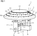
- Fig. 1 illustrates an embodiment of a gas burner 1 in an assembled state
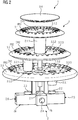
- Fig. 2 illustrates said gas burner 1 according to an exploded view
- the gas burner 1 comprises an injector holder 2.
- Said injector holder 2 may be adapted to be arranged below a work plate of a gas hob. In other words, the injector holder 2 may be integrated in the cooktop.
- the injector holder 2 comprises gas inlets 2.4, 2.5, 2.6 which are fluidly coupled with gas injectors 2.1, 2.2, 2.3.
- the injector holder 2 may comprise multiple end faces.
- the injector holder 2 may comprise a T-like or cross-like shape with a first and a second injector holder portion 2a, 2b and the gas inlets 2.4, 2.5, 2.6 are provided at the free ends of said injector holder portions 2a, 2b.
- the gas injectors 2.1, 2.2, 2.3 may be arranged at an upper side of the injector holder 2 in order to provide an upwardly directed gas flow.
- the gas injectors 2.1, 2.2, 2.3 may be arranged next to each other along a straight line.
- the gas burner 1 comprises a burner crown assembly 3.
- the burner crown assembly 3 may be adapted to be arranged above the injector holder 2.
- the burner crown assembly 3 may comprise multiple parts, namely a first burner crown 3.1, in the following also referred to as upper burner crown 3.1, a second burner crown 3.2, in the following also referred to as middle burner crown 3.2 and a third burner crown 3.3, in the following also referred to as lower burner crown 3.3.
- the burner crowns 3.1, 3.2, 3.3 comprise different sizes, namely the first burner crown 3.1 is the smallest one, the second burner crown 3.2 is greater than the first burner crown 3.1 but smaller than the third burner crown 3.3 and said third burner crown 3.3 is the biggest one.
- Said burner crowns 3.1, 3.2, 3.3 are adapted to be arranged concentrically and superimposed such that said burner crowns 3.1, 3.2, 3.3 can be stacked one above the other.
- the second and the third burner crown 3.2, 3.3 comprises a recess 3.2.3, 3.3.3 for receiving a lower portion of the burner crown 3.1, 3.2 arranged above.
- chambers CH2, CH3 may be obtained in an area between two adjacent burner crowns 3.1, 3.2, 3.3. More in detail, between a lower wall portion of the recess 3.2.3 of the second burner crown 3.2 and a lower wall portion of the first burner crown 3.1, a chamber CH2 may be formed.
- a further chamber CH3 is built between a lower wall portion of the recess 3.3.3 of the third burner crown 3.3 and a lower wall portion of the second burner crown 3.2.
- first burner crown 3.1 may comprise a recess 3.1.2 which is closed at its upper side by a burner cap 3.4, thereby forming a chamber CH1 between the first burner crown 3.1 and the burner cap 3.4.
- Said chambers CH1, CH2, CH3 may be, for example, radial Venturi effect chambers.
- Said chambers CH1, CH2, CH2 may be stacked on top of one another.
- each burner crown 3.1, 3.2, 3.3 comprise a flame ring FR1, FR2, FR3.
- Said flame ring FR1, FR2, FR3 is provided circumferentially at the respective burner crown 3.1, 3.2, 3.3.
- the flame rings FR1, FR2, FR3 may be arranged in a concentric manner with respect to the middle axis of the gas burner 1, respectively its burner crown assembly 3.
- the flame rings FR1, FR2, FR3 may be constituted by multiple openings or grooves provided through the circumferential side wall of the burner crowns 3.1, 3.2, 3.3. Said openings or grooves form flame ports of the burner.
- the burner crown assembly 3 comprises multiple pipes 3.1.1, 3.2.1, 3.3.1 adapted to provide a combustion gas mixture to said chamber CH1, CH2, CH3.
- Each pipe 3.1.1, 3.2.1, 3.3.1 may be associated with a certain chamber CH1, CH2, CH3.
- a first pipe 3.1.1 may be adapted to provide said combustion gas mixture to the first chamber CH1
- a second pipe 3.2.1 may be adapted to provide said combustion gas mixture to the second chamber CH2
- the third pipe 3.3.1 may be adapted to provide said combustion gas mixture to the third chamber CH3.
- Said pipe 3.1.1, 3.2.1, 3.3.1 may be Venturi effect pipes.
- Said pipes 3.1.1, 3.2.1, 3.3.1 may be vertically arranged within the burner crown assembly 3, i.e. the longitudinal axis of the respective pipe 3.1.1, 3.2.1, 3.3.1 is vertically arranged.
- Said pipe 3.1.1, 3.2.1, 3.3.1 may be, for example, an integral part of the respective burner crown 3.1, 3.2, 3.3.
- the pipe 3.1.1, 3.2.1, 3.3.1 may protrude at the lower side of the burner crown 3.1, 3.2, 3.3 and may have a first free end arranged within the respective chamber CH1, CH2, CH3 and a further free end arranged below the respective chamber CH1, CH2, CH3.
- Said further free end may be arranged closely above a gas injector 2.1, 2.2, 2.3.
- each gas injector 2.1, 2.2, 2.3 may be able to provide an upwardly directed steam of gas into said pipe 3.1.1, 3.2.1, 3.3.1 and said pipe 3.1.1, 3.2.1, 3.3.1 guides the gas into the chamber CH1, CH2, CH3 in which its upper free end is located.
- the lower free ends of the pipe 3.1.1, 3.2.1, 3.3.1 may be at least partially open in order to be able to suck primary air. Said primary air is mixed within the respective pipe 3.1.1, 3.2.1, 3.3.1 and the chambers CH1, CH2, CH3 in order to provide a combustion gas mixture at the flame rings FR1, FR2, FR3.
- said pipes 3.1.1, 3.2.1, 3.3.1 are arranged at a distance to each other.
- the pipe 3.1.1 (fluidly connected with the first, upper chamber CH1) may be arranged in the center of the burner crown assembly 3 and the pipes 3.2.1, 3.3.1 may be arranged at different sides of said pipe 3.1.1.
- the gas injectors 2.1, 2.2, 2.3 may be arranged at the injection holder 2 such that - in the assembled state of the gas burner 1 - the lower free ends of the pipes 3.1.1, 3.2.1, 3.3.1 are arranged directly above the respective gas injector 2.1, 2.2, 2.3.
- the second and third burner crown 3.2, 3.3 comprises a passage 3.2.2, 3.3.2 for said pipe(s). More in detail, the third burner crown 3.3 comprises two passages 3.3.2 for pipe 3.1.1 and pipe 3.2.1.
- the second burner crown 3.2 comprises a single passage 3.2.2 for pipe 3.1.1.
- Said passages 3.2.2, 3.3.2 may be arranged coaxially with the gas injectors 2.2, 2.3.
- the burner crows 3.1, 3.2, 3.3 can be arranged one above another and the pipes 3.1.1, 3.2.1 pass through the respective passages 3.2.2, 3.3.2.
- the gas burner 1 provides multiple gas burner stages with different heating power.
- small-sized flame ring FR1 may provide lower heating power than flame ring FR2 and flame ring FR2 may provide lower heating power than flame ring FR3.
- the gas burner may be adapted to be driven according to a three-stage power concept, namely a lower power stage in which only the first flame ring FR1 is active, a medium power stage in which the first and the second flame ring FR1, FR2 is active, and a maximum power level in which all flame rings FR1, FR2, FR3 are active.
- the heating power of the lower power stage may be, for example, in the range of 0.3KW to 1KW
- the medium power stage may be, for example, in the range of 1.6KW to 2.5KW
- the maximum power stage may be, for example, in the range of 1.6KW to 4KW.
- the burner cap 4 may be a single piece element made of drawn sheet metal, e.g. of steel, aluminum, brass, stainless steel, sintered steel or other suitable metal alloys.
- the burner crowns 3.1, 3.2, 3.3 may be preferably made of aluminum.
- the gas burner may comprise even more than three flame rings, respectively, burner crowns, e.g. four or five flame rings/ burner crowns.
Landscapes
- Engineering & Computer Science (AREA)
- Chemical & Material Sciences (AREA)
- Combustion & Propulsion (AREA)
- Mechanical Engineering (AREA)
- General Engineering & Computer Science (AREA)
- Gas Burners (AREA)
Abstract
- an injection holder (2) with at least three gas injectors (2.1, 2.2, 2.3) ;
- a burner crown assembly (3), the burner crown assembly (3) comprising at least three flame rings (FR1, FR2, FR3) with different sizes, the burner crown assembly (3) further comprising at least three chambers (CH1, CH2, CH3) and at least three pipes (3.1.1, 3.2.1, 3.3.1), each pipe (3.1.1, 3.2.1, 3.3.1) being fluidly coupled with a single chamber (CH1, CH2, CH3);
wherein each gas injector (2.1, 2.2, 2.3) is associated with one of said pipes (3.1.1, 3.2.1, 3.3.1) for providing gas into said pipe (3.1.1, 3.2.1, 3.3.1), said pipe (3.1.1, 3.2.1, 3.3.1) being adapted to receive primary air in the area of the injection holder (2) and to provide a combustion mixture of gas and primary air to one of said flame rings (FR1, FR2, FR3) of the burner crown assembly (3).
Description
- Generally, the present invention relates to the field of gas burners. More specifically, the present invention relates to a gas burner with multiple flame rings comprising different sizes for providing different heating power levels within a single gas burner.
- Gas burners are well-known in prior art. Specifically, cooking hob gas burners are known which comprise an injection holder, a burner crown and a burner cap. Said burner crown and burner cap form a combustion gas chamber providing a mixture of gas and primary air to a flame ring comprising a plurality of flame ports.
- Gas hobs are known which comprise multiple gas burners of different sizes, specifically, different diameters in order to provide burners with different heating power levels.
- Disadvantageously, current gas hobs do not provide the possibility to provide heat at multiple high-power, large-sized burners. So, in case that the gas hob comprises four burners and four pieces of cookware should be heated at high-power burners, gas burners have to be used which do not have the desired power level.
- It is an objective of the embodiments of the present invention to provide a gas burner with improved flexibility in view of the heating power range provided by the gas burner. The objective is solved by the features of the independent claims. Preferred embodiments are given in the dependent claims. If not explicitly indicated otherwise, embodiments of the invention and single features of said embodiments can be freely combined with each other.
- According to an aspect, the invention relates to a gas burner comprising:
- an injection holder with at least three gas injectors; and
- a burner crown assembly, the burner crown assembly comprising at least three flame rings with different sizes, the burner crown assembly further comprising at least three chambers and at least three pipes, each pipe being fluidly coupled with a single chamber.
- Each gas injector is associated with one of said pipes for providing gas into said pipe, said pipe being adapted to receive primary air in the area of the injection holder and to provide a combustion mixture of gas and primary air to one of said flame rings of the burner crown assembly.
- Said gas burner is advantageous because due to the at least three different-sized flame rings said gas burner can provide a small heating power by only powering the smallest flame ring or a higher heating power by powering two or more of said flame rings.
- According to embodiments, the burner crown assembly comprises at least three burner crowns of different sizes wherein a smaller-sized burner crown is at least partially inserted at an upper-side recess of the next-sized burner crown. Said burner crowns may be superimposed or stacked such that an upper burner crown is at least partially received within the recess of a burner crown arranged below. According to an embodiment, said burner crown assembly may be disassembled into multiple burner crowns which have different sizes. Preferably, said burner crowns may be arranged concentrically. The assembled burner crown assembly may comprise a shape according to a truncated cone.
- According to embodiments, a lower wall portion of an upper burner crown provides an upper boundary for the chamber provided within a lower burner crown. So, in other words, the recess provided within a certain burner crown is limited at the top side by a bottom portion of the burner crown arranged above in order to form a gas mixture chamber within the respective burner crown.
- According to embodiments, the chambers are separated from each other with respect to the provision of a combustion mixture of gas and primary air into the respective chamber. So, the combustion gas mixture provided to a certain chamber is not able to flow into another chamber provided above or below. Thereby, said combustion gas mixture can be provided to each flame ring separately
- According to embodiments, each gas injector is coupled with a separate gas inlet. The gas inlet may be, for example, provided at the injection holder. Thereby it is possible to control the provision of gas separately to each chamber, respectively to each flame ring.
- According to embodiments, the burner crown assembly is arranged above the injection holder. So, gas provided by the gas injectors arranged at the injection holder can flow upwardly into the respective chamber in order to be guided by said chamber towards the flame ports of the flame ring which are circumferentially arranged at the respective burner crown.
- According to embodiments, the pipes are arranged at a lateral distance to each other. Thereby it is possible to arrange separate gas injectors below the free end of the pipes in order to provide selectively gas into said pipes.
- According to embodiments, the pipes are arranged next to each other in a straight line. Said arrangement is advantageous because the provision of gas to said pipes is simplified. The arrangement of the gas injectors may be chosen similarly in order to enable a technically simple provision of gas to said pipes.
- According to embodiments, the pipe of the upper burner crown is arranged in the centre of the burner crown assembly. Said configuration is advantageous because the upper burner crown comprises the smallest cross-sectional area and due to the centred arrangement of the pipe, the construction of the burner crown assembly is simplified and a homogenous flame formation at the first flame ring is obtained.
- According to embodiments, the longitudinal axes of the pipes are vertically arranged. Thereby, the gas guided within the pipe can flow upwardly through the pipe thereby being mixed with the primary air sucked at the bottom of the pipe.
- According to embodiments, the chamber of the upper burner crown is covered by a burner cap. Said burner cap may close a recess provided in the upper burner crown in order to form said chamber.
- According to embodiments, each pipe comprises at its bottom an open free end. Said open free end provides an air inlet at which primary air is sucked in in order to be mixed with the gas provided by the gas injector. Said air inlet may be provided below a workplate of the gas burner (also referred to as bottom breather technology).
- According to embodiments, the burner crown assembly comprises at least an upper, a middle and a lower burner crown, wherein the middle burner crown comprise at least one passage for the pipe of the upper burner crown and the lower burner crown comprises at least two passages for the pipes of the upper and middle burner crown. Thereby it is possible that the pipes can pass through the respective burner crowns or cambers.
- According to embodiments, at least the upper burner crown comprises a passage for a spark plug and/or a thermocouple. Said spark plug and/or thermocouple may be arranged within the upper burner crown or in an area between the upper and middle burner crown. Thereby the ignition behaviour and operational safety is significantly improved.
- According to a further aspect, the invention refers to a gas hob with a gas burner configured according to anyone of the preceding embodiments.
- The terms "essentially", "substantially" or "approximately" as used in the invention means deviations from the exact value by +/- 10%, preferably by +/- 5% and/or deviations in the form of changes that are insignificant for the function.
- The various aspects of the invention, including its particular features and advantages, will be readily understood from the following detailed description and the accompanying drawings, in which:
- Fig. 1
- shows an example perspective view of a gas burner according to an embodiment; and
- Fig. 2
- shows an example exploded perspective view of the gas burner according to
Fig. 1 . - The present invention will now be described more fully with reference to the accompanying drawings, in which example embodiments are shown. However, this invention should not be construed as limited to the embodiments set forth herein. Throughout the following description similar reference numerals have been used to denote similar elements, parts, items or features, when applicable.
-
Fig. 1 illustrates an embodiment of agas burner 1 in an assembled state andFig. 2 illustrates saidgas burner 1 according to an exploded view. Thegas burner 1 comprises aninjector holder 2. Saidinjector holder 2 may be adapted to be arranged below a work plate of a gas hob. In other words, theinjector holder 2 may be integrated in the cooktop. Theinjector holder 2 comprises gas inlets 2.4, 2.5, 2.6 which are fluidly coupled with gas injectors 2.1, 2.2, 2.3. - According to an embodiment, the
injector holder 2 may comprise multiple end faces. For example, theinjector holder 2 may comprise a T-like or cross-like shape with a first and a secondinjector holder portion injector holder portions injector holder 2 in order to provide an upwardly directed gas flow. For example, the gas injectors 2.1, 2.2, 2.3 may be arranged next to each other along a straight line. - In addition, the
gas burner 1 comprises aburner crown assembly 3. Theburner crown assembly 3 may be adapted to be arranged above theinjector holder 2. Theburner crown assembly 3 may comprise multiple parts, namely a first burner crown 3.1, in the following also referred to as upper burner crown 3.1, a second burner crown 3.2, in the following also referred to as middle burner crown 3.2 and a third burner crown 3.3, in the following also referred to as lower burner crown 3.3. As shown infig. 2 , the burner crowns 3.1, 3.2, 3.3 comprise different sizes, namely the first burner crown 3.1 is the smallest one, the second burner crown 3.2 is greater than the first burner crown 3.1 but smaller than the third burner crown 3.3 and said third burner crown 3.3 is the biggest one. Said burner crowns 3.1, 3.2, 3.3 are adapted to be arranged concentrically and superimposed such that said burner crowns 3.1, 3.2, 3.3 can be stacked one above the other. - More in detail, the second and the third burner crown 3.2, 3.3 comprises a recess 3.2.3, 3.3.3 for receiving a lower portion of the burner crown 3.1, 3.2 arranged above. When arranging the burner crowns 3.1, 3.2, 3.3 above each other, chambers CH2, CH3 may be obtained in an area between two adjacent burner crowns 3.1, 3.2, 3.3. More in detail, between a lower wall portion of the recess 3.2.3 of the second burner crown 3.2 and a lower wall portion of the first burner crown 3.1, a chamber CH2 may be formed. A further chamber CH3 is built between a lower wall portion of the recess 3.3.3 of the third burner crown 3.3 and a lower wall portion of the second burner crown 3.2. In addition, also the first burner crown 3.1 may comprise a recess 3.1.2 which is closed at its upper side by a burner cap 3.4, thereby forming a chamber CH1 between the first burner crown 3.1 and the burner cap 3.4. Said chambers CH1, CH2, CH3 may be, for example, radial Venturi effect chambers. Said chambers CH1, CH2, CH2 may be stacked on top of one another.
- In order to provide a combustion gas mixture, each burner crown 3.1, 3.2, 3.3 comprise a flame ring FR1, FR2, FR3. Said flame ring FR1, FR2, FR3 is provided circumferentially at the respective burner crown 3.1, 3.2, 3.3. As shown in
Fig. 1 , the flame rings FR1, FR2, FR3 may be arranged in a concentric manner with respect to the middle axis of thegas burner 1, respectively itsburner crown assembly 3. The flame rings FR1, FR2, FR3 may be constituted by multiple openings or grooves provided through the circumferential side wall of the burner crowns 3.1, 3.2, 3.3. Said openings or grooves form flame ports of the burner. - In order to be able to selectively provide a combustion gas mixture in a certain chamber CH1, CH2, CH3, the chambers CH1, CH2, CH3 are separated from each other and said combustion gas mixture is provided separately to each chamber CH1, CH2, CH3. More in detail, the
burner crown assembly 3 comprises multiple pipes 3.1.1, 3.2.1, 3.3.1 adapted to provide a combustion gas mixture to said chamber CH1, CH2, CH3. Each pipe 3.1.1, 3.2.1, 3.3.1 may be associated with a certain chamber CH1, CH2, CH3. For example, a first pipe 3.1.1 may be adapted to provide said combustion gas mixture to the first chamber CH1, a second pipe 3.2.1 may be adapted to provide said combustion gas mixture to the second chamber CH2 and the third pipe 3.3.1 may be adapted to provide said combustion gas mixture to the third chamber CH3. Said pipe 3.1.1, 3.2.1, 3.3.1 may be Venturi effect pipes. - Said pipes 3.1.1, 3.2.1, 3.3.1 may be vertically arranged within the
burner crown assembly 3, i.e. the longitudinal axis of the respective pipe 3.1.1, 3.2.1, 3.3.1 is vertically arranged. Said pipe 3.1.1, 3.2.1, 3.3.1 may be, for example, an integral part of the respective burner crown 3.1, 3.2, 3.3. The pipe 3.1.1, 3.2.1, 3.3.1 may protrude at the lower side of the burner crown 3.1, 3.2, 3.3 and may have a first free end arranged within the respective chamber CH1, CH2, CH3 and a further free end arranged below the respective chamber CH1, CH2, CH3. Said further free end may be arranged closely above a gas injector 2.1, 2.2, 2.3. Thereby, the each gas injector 2.1, 2.2, 2.3 may be able to provide an upwardly directed steam of gas into said pipe 3.1.1, 3.2.1, 3.3.1 and said pipe 3.1.1, 3.2.1, 3.3.1 guides the gas into the chamber CH1, CH2, CH3 in which its upper free end is located. - The lower free ends of the pipe 3.1.1, 3.2.1, 3.3.1 may be at least partially open in order to be able to suck primary air. Said primary air is mixed within the respective pipe 3.1.1, 3.2.1, 3.3.1 and the chambers CH1, CH2, CH3 in order to provide a combustion gas mixture at the flame rings FR1, FR2, FR3.
- As shown in
Fig 1 , said pipes 3.1.1, 3.2.1, 3.3.1 are arranged at a distance to each other. The pipe 3.1.1 (fluidly connected with the first, upper chamber CH1) may be arranged in the center of theburner crown assembly 3 and the pipes 3.2.1, 3.3.1 may be arranged at different sides of said pipe 3.1.1. The gas injectors 2.1, 2.2, 2.3 may be arranged at theinjection holder 2 such that - in the assembled state of the gas burner 1 - the lower free ends of the pipes 3.1.1, 3.2.1, 3.3.1 are arranged directly above the respective gas injector 2.1, 2.2, 2.3. - In order to enable the pipes 3.1.1, 3.2.1 to pass through the chambers CH2, CH3, the second and third burner crown 3.2, 3.3 comprises a passage 3.2.2, 3.3.2 for said pipe(s). More in detail, the third burner crown 3.3 comprises two passages 3.3.2 for pipe 3.1.1 and pipe 3.2.1. The second burner crown 3.2 comprises a single passage 3.2.2 for pipe 3.1.1. Said passages 3.2.2, 3.3.2 may be arranged coaxially with the gas injectors 2.2, 2.3. Thus, during assembling of the
gas burner 1, the burner crows 3.1, 3.2, 3.3 can be arranged one above another and the pipes 3.1.1, 3.2.1 pass through the respective passages 3.2.2, 3.3.2. - Due to the different size of the flame rings FR1, FR2, FR3, respectively the burner crowns 3.1, 3.2, 3.3, the
gas burner 1 provides multiple gas burner stages with different heating power. For example, small-sized flame ring FR1 may provide lower heating power than flame ring FR2 and flame ring FR2 may provide lower heating power than flame ring FR3. - The gas burner may be adapted to be driven according to a three-stage power concept, namely a lower power stage in which only the first flame ring FR1 is active, a medium power stage in which the first and the second flame ring FR1, FR2 is active, and a maximum power level in which all flame rings FR1, FR2, FR3 are active. The heating power of the lower power stage may be, for example, in the range of 0.3KW to 1KW, the medium power stage may be, for example, in the range of 1.6KW to 2.5KW and the maximum power stage may be, for example, in the range of 1.6KW to 4KW.
- The
burner cap 4 may be a single piece element made of drawn sheet metal, e.g. of steel, aluminum, brass, stainless steel, sintered steel or other suitable metal alloys. - The burner crowns 3.1, 3.2, 3.3 may be preferably made of aluminum.
- In the disclosure before, an embodiment with three flame rings, respectively, burner crowns have been described. It is worth mentioning that the gas burner may comprise even more than three flame rings, respectively, burner crowns, e.g. four or five flame rings/ burner crowns.
- It should be noted that the description and drawings merely illustrate the principles of the proposed gas burner. Those skilled in the art will be able to implement various arrangements that, although not explicitly described or shown herein, embody the principles of the invention.
-
- 1
- gas burner
- 2
- injection holder
- 2a
- injection holder portion
- 2b
- injection holder portion
- 2.1, 2.2, 2.3
- gas injector
- 2.4, 2.5, 2.6
- gas inlet
- 3
- burner crown assembly
- 3.1
- first burner crown
- 3.1.1
- pipe
- 3.1.2
- recess
- 3.2
- second burner crown
- 3.2.1
- pipe
- 3.2.2
- passage
- 3.2.3
- recess
- 3.3
- third burner crown
- 3.3.1
- pipe
- 3.3.2
- passage
- 3.3.3
- recess
- 3.4
- burner cap
- 4
- spark plug
- 5
- thermocouple
- CH1
- first chamber
- CH2
- second chamber
- CH3
- third chamber
- FR1
- first flame ring
- FR2
- second flame ring
- FR3
- third flame ring
Claims (15)
- Gas burner comprising:- an injection holder (2) with at least three gas injectors (2.1, 2.2, 2.3);- a burner crown assembly (3), the burner crown assembly (3) comprising at least three flame rings (FR1, FR2, FR3) with different sizes, the burner crown assembly (3) further comprising at least three chambers (CH1, CH2, CH3) and at least three pipes (3.1.1, 3.2.1, 3.3.1), each pipe (3.1.1, 3.2.1, 3.3.1) being fluidly coupled with a single chamber (CH1, CH2, CH3);wherein each gas injector (2.1, 2.2, 2.3) is associated with one of said pipes (3.1.1, 3.2.1, 3.3.1) for providing gas into said pipe (3.1.1, 3.2.1, 3.3.1), said pipe (3.1.1, 3.2.1, 3.3.1) being adapted to receive primary air in the area of the injection holder (2) and to provide a combustion mixture of gas and primary air to one of said flame rings (FR1, FR2, FR3) of the burner crown assembly (3).
- Gas burner according to claim 1, wherein the burner crown assembly (3) comprises at least three burner crowns (3.1, 3.2, 3.3) of different sizes wherein a smaller-sized burner crown (3.1, 3.2) is at least partially inserted at an upper-side recess of the next-sized burner crown (3.2, 3.3).
- Gas burner according to claim 2, wherein a lower wall portion of an upper burner crown (3.1, 3.2) provides an upper boundary for the chamber (CH2, CH3) provided within a lower burner crown (3.2, 3.3).
- Gas burner according to anyone of the preceding claims, wherein the chambers (CH1, CH2, CH3) are separated from each other with respect to the provision of a combustion mixture of gas and primary air into the respective chamber (CH1, CH2, CH3).
- Gas burner according to anyone of the preceding claims, wherein each gas injector (2.1, 2.2, 2.3) is coupled with a separate gas inlet (2.4, 2.5, 2.6).
- Gas burner according to anyone of the preceding claims, wherein the burner crown (3) assembly is arranged above the injection holder (2).
- Gas burner according to anyone of the preceding claims, wherein the pipes (3.1.1, 3.2.1, 3.3.1) are arranged at a lateral distance to each other.
- Gas burner according to anyone of the preceding claims, wherein the pipes (3.1.1, 3.2.1, 3.3.1) are arranged next to each other in a straight line.
- Gas burner according to anyone of the preceding claims 2 to 8, wherein the pipe (3.1.1) of the upper burner crown (3.1) is arranged in the centre of the burner crown assembly (3).
- Gas burner according to anyone of the preceding claims, wherein the longitudinal axes of the pipes (3.1.1, 3.2.1, 3.3.1) are vertically arranged.
- Gas burner according to anyone of the preceding claims, wherein the chamber (CH1) of the upper burner crown (3.1) is covered by a burner cap.
- Gas burner according to anyone of the preceding claims, wherein each pipe (3.1.1, 3.2.1, 3.3.1) comprise at its bottom an open free end.
- Gas burner according to anyone of the preceding claims, wherein the burner crown assembly (3) comprises at least an upper, a middle and a lower burner crown (3.1, 3.2, 3.3), wherein the middle burner crown (3.2) comprise at least one passage (3.2.2) for the pipe (3.1.1) of the upper burner crown (3.1) and the lower burner crown (3.3) comprises at least two passages (3.2.2, 3.3.2) for the pipes (3.1.1, 3.2.1) of the upper and middle burner crown (3.1, 3.2).
- Gas burner according to anyone of the preceding claims, wherein at least the upper burner crown (3.1) comprises a passage for a spark plug (4) and/or a thermocouple (5).
- Cooking hob comprising a gas burner (1) configured according to anyone of the preceding claims.
Priority Applications (7)
| Application Number | Priority Date | Filing Date | Title |
|---|---|---|---|
| EP16205401.9A EP3339731B1 (en) | 2016-12-20 | 2016-12-20 | Gas burner and hob comprising a gas burner |
| ES16205401T ES2747707T3 (en) | 2016-12-20 | 2016-12-20 | Gas burner and cooking hob comprising a gas burner |
| CN201780078491.3A CN110088529A (en) | 2016-12-20 | 2017-11-20 | Gas burner and kitchen range including gas burner |
| BR112019012596-5A BR112019012596A2 (en) | 2016-12-20 | 2017-11-20 | gas burner and ceramic hob |
| AU2017383864A AU2017383864A1 (en) | 2016-12-20 | 2017-11-20 | Gas burner and hob comprising a gas burner |
| PCT/EP2017/079803 WO2018114169A1 (en) | 2016-12-20 | 2017-11-20 | Gas burner and hob comprising a gas burner |
| US16/465,886 US20190331337A1 (en) | 2016-12-20 | 2017-11-20 | Gas burner and hob comprising a gas burner |
Applications Claiming Priority (1)
| Application Number | Priority Date | Filing Date | Title |
|---|---|---|---|
| EP16205401.9A EP3339731B1 (en) | 2016-12-20 | 2016-12-20 | Gas burner and hob comprising a gas burner |
Publications (2)
| Publication Number | Publication Date |
|---|---|
| EP3339731A1 true EP3339731A1 (en) | 2018-06-27 |
| EP3339731B1 EP3339731B1 (en) | 2019-07-24 |
Family
ID=57570831
Family Applications (1)
| Application Number | Title | Priority Date | Filing Date |
|---|---|---|---|
| EP16205401.9A Not-in-force EP3339731B1 (en) | 2016-12-20 | 2016-12-20 | Gas burner and hob comprising a gas burner |
Country Status (7)
| Country | Link |
|---|---|
| US (1) | US20190331337A1 (en) |
| EP (1) | EP3339731B1 (en) |
| CN (1) | CN110088529A (en) |
| AU (1) | AU2017383864A1 (en) |
| BR (1) | BR112019012596A2 (en) |
| ES (1) | ES2747707T3 (en) |
| WO (1) | WO2018114169A1 (en) |
Cited By (1)
| Publication number | Priority date | Publication date | Assignee | Title |
|---|---|---|---|---|
| WO2023066939A1 (en) * | 2021-10-22 | 2023-04-27 | Electrolux Appliances Aktiebolag | Method for manufacturing gas stove and gas stove |
Families Citing this family (4)
| Publication number | Priority date | Publication date | Assignee | Title |
|---|---|---|---|---|
| US11234557B2 (en) * | 2018-03-14 | 2022-02-01 | Ashley Bryant | Stovetop cooking and grilling assembly |
| USD926520S1 (en) | 2019-01-09 | 2021-08-03 | Whirlpool Corporation | Cooking burner |
| KR20230111906A (en) * | 2022-01-19 | 2023-07-26 | 삼성전자주식회사 | Burner device |
| US20230228416A1 (en) * | 2022-01-19 | 2023-07-20 | Samsung Electronics Co., Ltd. | Burner device |
Citations (1)
| Publication number | Priority date | Publication date | Assignee | Title |
|---|---|---|---|---|
| WO2006114063A1 (en) * | 2005-05-20 | 2006-11-02 | Zhejiang Shuaikang Electric Stock Co., Ltd. | A gas burner |
Family Cites Families (10)
| Publication number | Priority date | Publication date | Assignee | Title |
|---|---|---|---|---|
| US6132205A (en) * | 2000-01-06 | 2000-10-17 | Harneit; Uwe | Multi-ring sealed gas burner |
| CN1289908A (en) * | 2000-10-17 | 2001-04-04 | 上海煤气表具股份有限公司 | Burner of civil gas stove |
| CN101089468A (en) * | 2007-05-25 | 2007-12-19 | 江苏光芒燃具股份有限公司 | High energy, whole oxygen supply, three-gas compatible burner |
| ES2719203T3 (en) * | 2007-10-23 | 2019-07-09 | Electrolux Home Products Corp Nv | Enhanced gas burner |
| MX345335B (en) * | 2009-12-18 | 2017-01-25 | Mabe S A De C V * | Triple flame section burner. |
| MX337534B (en) * | 2011-10-14 | 2016-03-09 | Mabe Sa De Cv | Delta burner. |
| CN104713087B (en) * | 2015-03-12 | 2017-10-27 | 广东美的厨房电器制造有限公司 | Bottom cup lid and burner and gas appliance |
| ITUB20153850A1 (en) * | 2015-04-24 | 2017-03-24 | Defendi Italy Srl | GAS BURNER WITH MORE FLAME CHAINS FOR COOKTOPS. |
| US9664394B2 (en) * | 2015-06-11 | 2017-05-30 | Haier Us Appliance Solutions, Inc. | Multi-ring gas burner |
| CA2934675A1 (en) * | 2015-07-02 | 2017-01-02 | Mabe, S.A. De C.V. | Multi burner ovni |
-
2016
- 2016-12-20 EP EP16205401.9A patent/EP3339731B1/en not_active Not-in-force
- 2016-12-20 ES ES16205401T patent/ES2747707T3/en active Active
-
2017
- 2017-11-20 BR BR112019012596-5A patent/BR112019012596A2/en not_active Application Discontinuation
- 2017-11-20 WO PCT/EP2017/079803 patent/WO2018114169A1/en not_active Ceased
- 2017-11-20 CN CN201780078491.3A patent/CN110088529A/en active Pending
- 2017-11-20 AU AU2017383864A patent/AU2017383864A1/en not_active Abandoned
- 2017-11-20 US US16/465,886 patent/US20190331337A1/en not_active Abandoned
Patent Citations (1)
| Publication number | Priority date | Publication date | Assignee | Title |
|---|---|---|---|---|
| WO2006114063A1 (en) * | 2005-05-20 | 2006-11-02 | Zhejiang Shuaikang Electric Stock Co., Ltd. | A gas burner |
Cited By (1)
| Publication number | Priority date | Publication date | Assignee | Title |
|---|---|---|---|---|
| WO2023066939A1 (en) * | 2021-10-22 | 2023-04-27 | Electrolux Appliances Aktiebolag | Method for manufacturing gas stove and gas stove |
Also Published As
| Publication number | Publication date |
|---|---|
| ES2747707T3 (en) | 2020-03-11 |
| BR112019012596A2 (en) | 2019-11-19 |
| AU2017383864A1 (en) | 2019-05-23 |
| EP3339731B1 (en) | 2019-07-24 |
| US20190331337A1 (en) | 2019-10-31 |
| WO2018114169A1 (en) | 2018-06-28 |
| CN110088529A (en) | 2019-08-02 |
Similar Documents
| Publication | Publication Date | Title |
|---|---|---|
| EP3339731B1 (en) | Gas burner and hob comprising a gas burner | |
| EP3306192B1 (en) | Cap to change inner flame burner to vertical flame | |
| EP3404325B1 (en) | Burner cap base for burner of a gas cooktop, burner, and gas cooktop | |
| EP3263986A1 (en) | High efficiency high power inner flame burner | |
| CN108870390B (en) | Gas stove and fire cover, burner and burner of burner for gas stove | |
| WO2013113497A2 (en) | A gas burner for a domestic cooktop | |
| US11346550B2 (en) | Burner of gas stove | |
| CA2791972A1 (en) | Delta burner | |
| CN206989200U (en) | Burner, burner and the gas-cooker of burner for gas kitchen range | |
| AU2016214700B2 (en) | A gas burner assembly | |
| CN108087923B (en) | Fire cover and burner | |
| US11268700B2 (en) | Gas burner and hob comprising a gas burner | |
| CN108870395A (en) | Fire cover pedestal, burner, burner and the gas-cooker of burner for gas kitchen range | |
| CN109595556B (en) | Stove burner | |
| EP3591289B1 (en) | A dual circuit burner, a gas burner arrangement and a gas stove | |
| EP4449019B1 (en) | Burner head for cooktop, burner, and cooktop | |
| CN110160045A (en) | A kind of three ring fire kitchen range blast burners | |
| US20160201921A1 (en) | High Power Dual Gas Burner | |
| CN103486586A (en) | Inner flame cover for domestic gas burners and burner with inner flame cover | |
| JP2005188897A (en) | Burner equipment | |
| CN223740790U (en) | Inner fire cover and burner | |
| EP3748230B1 (en) | Gas burner assembly | |
| CN210485700U (en) | Internal combustion type stove burner | |
| CN119665232A (en) | Internal fire cover and burner | |
| CN121761342A (en) | gas stove |
Legal Events
| Date | Code | Title | Description |
|---|---|---|---|
| PUAI | Public reference made under article 153(3) epc to a published international application that has entered the european phase |
Free format text: ORIGINAL CODE: 0009012 |
|
| STAA | Information on the status of an ep patent application or granted ep patent |
Free format text: STATUS: THE APPLICATION HAS BEEN PUBLISHED |
|
| AK | Designated contracting states |
Kind code of ref document: A1 Designated state(s): AL AT BE BG CH CY CZ DE DK EE ES FI FR GB GR HR HU IE IS IT LI LT LU LV MC MK MT NL NO PL PT RO RS SE SI SK SM TR |
|
| AX | Request for extension of the european patent |
Extension state: BA ME |
|
| STAA | Information on the status of an ep patent application or granted ep patent |
Free format text: STATUS: REQUEST FOR EXAMINATION WAS MADE |
|
| 17P | Request for examination filed |
Effective date: 20190102 |
|
| GRAP | Despatch of communication of intention to grant a patent |
Free format text: ORIGINAL CODE: EPIDOSNIGR1 |
|
| RBV | Designated contracting states (corrected) |
Designated state(s): AL AT BE BG CH CY CZ DE DK EE ES FI FR GB GR HR HU IE IS IT LI LT LU LV MC MK MT NL NO PL PT RO RS SE SI SK SM TR |
|
| STAA | Information on the status of an ep patent application or granted ep patent |
Free format text: STATUS: GRANT OF PATENT IS INTENDED |
|
| INTG | Intention to grant announced |
Effective date: 20190221 |
|
| GRAS | Grant fee paid |
Free format text: ORIGINAL CODE: EPIDOSNIGR3 |
|
| GRAA | (expected) grant |
Free format text: ORIGINAL CODE: 0009210 |
|
| STAA | Information on the status of an ep patent application or granted ep patent |
Free format text: STATUS: THE PATENT HAS BEEN GRANTED |
|
| AK | Designated contracting states |
Kind code of ref document: B1 Designated state(s): AL AT BE BG CH CY CZ DE DK EE ES FI FR GB GR HR HU IE IS IT LI LT LU LV MC MK MT NL NO PL PT RO RS SE SI SK SM TR |
|
| REG | Reference to a national code |
Ref country code: GB Ref legal event code: FG4D |
|
| REG | Reference to a national code |
Ref country code: CH Ref legal event code: EP |
|
| REG | Reference to a national code |
Ref country code: DE Ref legal event code: R096 Ref document number: 602016017257 Country of ref document: DE |
|
| REG | Reference to a national code |
Ref country code: AT Ref legal event code: REF Ref document number: 1158639 Country of ref document: AT Kind code of ref document: T Effective date: 20190815 |
|
| REG | Reference to a national code |
Ref country code: IE Ref legal event code: FG4D |
|
| REG | Reference to a national code |
Ref country code: NL Ref legal event code: MP Effective date: 20190724 |
|
| REG | Reference to a national code |
Ref country code: LT Ref legal event code: MG4D |
|
| REG | Reference to a national code |
Ref country code: AT Ref legal event code: MK05 Ref document number: 1158639 Country of ref document: AT Kind code of ref document: T Effective date: 20190724 |
|
| PG25 | Lapsed in a contracting state [announced via postgrant information from national office to epo] |
Ref country code: HR Free format text: LAPSE BECAUSE OF FAILURE TO SUBMIT A TRANSLATION OF THE DESCRIPTION OR TO PAY THE FEE WITHIN THE PRESCRIBED TIME-LIMIT Effective date: 20190724 Ref country code: SE Free format text: LAPSE BECAUSE OF FAILURE TO SUBMIT A TRANSLATION OF THE DESCRIPTION OR TO PAY THE FEE WITHIN THE PRESCRIBED TIME-LIMIT Effective date: 20190724 Ref country code: FI Free format text: LAPSE BECAUSE OF FAILURE TO SUBMIT A TRANSLATION OF THE DESCRIPTION OR TO PAY THE FEE WITHIN THE PRESCRIBED TIME-LIMIT Effective date: 20190724 Ref country code: NO Free format text: LAPSE BECAUSE OF FAILURE TO SUBMIT A TRANSLATION OF THE DESCRIPTION OR TO PAY THE FEE WITHIN THE PRESCRIBED TIME-LIMIT Effective date: 20191024 Ref country code: AT Free format text: LAPSE BECAUSE OF FAILURE TO SUBMIT A TRANSLATION OF THE DESCRIPTION OR TO PAY THE FEE WITHIN THE PRESCRIBED TIME-LIMIT Effective date: 20190724 Ref country code: PT Free format text: LAPSE BECAUSE OF FAILURE TO SUBMIT A TRANSLATION OF THE DESCRIPTION OR TO PAY THE FEE WITHIN THE PRESCRIBED TIME-LIMIT Effective date: 20191125 Ref country code: NL Free format text: LAPSE BECAUSE OF FAILURE TO SUBMIT A TRANSLATION OF THE DESCRIPTION OR TO PAY THE FEE WITHIN THE PRESCRIBED TIME-LIMIT Effective date: 20190724 Ref country code: BG Free format text: LAPSE BECAUSE OF FAILURE TO SUBMIT A TRANSLATION OF THE DESCRIPTION OR TO PAY THE FEE WITHIN THE PRESCRIBED TIME-LIMIT Effective date: 20191024 Ref country code: LT Free format text: LAPSE BECAUSE OF FAILURE TO SUBMIT A TRANSLATION OF THE DESCRIPTION OR TO PAY THE FEE WITHIN THE PRESCRIBED TIME-LIMIT Effective date: 20190724 |
|
| PG25 | Lapsed in a contracting state [announced via postgrant information from national office to epo] |
Ref country code: RS Free format text: LAPSE BECAUSE OF FAILURE TO SUBMIT A TRANSLATION OF THE DESCRIPTION OR TO PAY THE FEE WITHIN THE PRESCRIBED TIME-LIMIT Effective date: 20190724 Ref country code: LV Free format text: LAPSE BECAUSE OF FAILURE TO SUBMIT A TRANSLATION OF THE DESCRIPTION OR TO PAY THE FEE WITHIN THE PRESCRIBED TIME-LIMIT Effective date: 20190724 Ref country code: AL Free format text: LAPSE BECAUSE OF FAILURE TO SUBMIT A TRANSLATION OF THE DESCRIPTION OR TO PAY THE FEE WITHIN THE PRESCRIBED TIME-LIMIT Effective date: 20190724 Ref country code: GR Free format text: LAPSE BECAUSE OF FAILURE TO SUBMIT A TRANSLATION OF THE DESCRIPTION OR TO PAY THE FEE WITHIN THE PRESCRIBED TIME-LIMIT Effective date: 20191025 Ref country code: IS Free format text: LAPSE BECAUSE OF FAILURE TO SUBMIT A TRANSLATION OF THE DESCRIPTION OR TO PAY THE FEE WITHIN THE PRESCRIBED TIME-LIMIT Effective date: 20191124 |
|
| PGFP | Annual fee paid to national office [announced via postgrant information from national office to epo] |
Ref country code: IT Payment date: 20191231 Year of fee payment: 4 |
|
| REG | Reference to a national code |
Ref country code: ES Ref legal event code: FG2A Ref document number: 2747707 Country of ref document: ES Kind code of ref document: T3 Effective date: 20200311 |
|
| PG25 | Lapsed in a contracting state [announced via postgrant information from national office to epo] |
Ref country code: TR Free format text: LAPSE BECAUSE OF FAILURE TO SUBMIT A TRANSLATION OF THE DESCRIPTION OR TO PAY THE FEE WITHIN THE PRESCRIBED TIME-LIMIT Effective date: 20190724 |
|
| PG25 | Lapsed in a contracting state [announced via postgrant information from national office to epo] |
Ref country code: EE Free format text: LAPSE BECAUSE OF FAILURE TO SUBMIT A TRANSLATION OF THE DESCRIPTION OR TO PAY THE FEE WITHIN THE PRESCRIBED TIME-LIMIT Effective date: 20190724 Ref country code: PL Free format text: LAPSE BECAUSE OF FAILURE TO SUBMIT A TRANSLATION OF THE DESCRIPTION OR TO PAY THE FEE WITHIN THE PRESCRIBED TIME-LIMIT Effective date: 20190724 Ref country code: RO Free format text: LAPSE BECAUSE OF FAILURE TO SUBMIT A TRANSLATION OF THE DESCRIPTION OR TO PAY THE FEE WITHIN THE PRESCRIBED TIME-LIMIT Effective date: 20190724 Ref country code: DK Free format text: LAPSE BECAUSE OF FAILURE TO SUBMIT A TRANSLATION OF THE DESCRIPTION OR TO PAY THE FEE WITHIN THE PRESCRIBED TIME-LIMIT Effective date: 20190724 |
|
| PG25 | Lapsed in a contracting state [announced via postgrant information from national office to epo] |
Ref country code: SM Free format text: LAPSE BECAUSE OF FAILURE TO SUBMIT A TRANSLATION OF THE DESCRIPTION OR TO PAY THE FEE WITHIN THE PRESCRIBED TIME-LIMIT Effective date: 20190724 Ref country code: CZ Free format text: LAPSE BECAUSE OF FAILURE TO SUBMIT A TRANSLATION OF THE DESCRIPTION OR TO PAY THE FEE WITHIN THE PRESCRIBED TIME-LIMIT Effective date: 20190724 Ref country code: IS Free format text: LAPSE BECAUSE OF FAILURE TO SUBMIT A TRANSLATION OF THE DESCRIPTION OR TO PAY THE FEE WITHIN THE PRESCRIBED TIME-LIMIT Effective date: 20200224 Ref country code: SK Free format text: LAPSE BECAUSE OF FAILURE TO SUBMIT A TRANSLATION OF THE DESCRIPTION OR TO PAY THE FEE WITHIN THE PRESCRIBED TIME-LIMIT Effective date: 20190724 |
|
| REG | Reference to a national code |
Ref country code: DE Ref legal event code: R097 Ref document number: 602016017257 Country of ref document: DE |
|
| REG | Reference to a national code |
Ref country code: DE Ref legal event code: R119 Ref document number: 602016017257 Country of ref document: DE |
|
| PLBE | No opposition filed within time limit |
Free format text: ORIGINAL CODE: 0009261 |
|
| STAA | Information on the status of an ep patent application or granted ep patent |
Free format text: STATUS: NO OPPOSITION FILED WITHIN TIME LIMIT |
|
| PG2D | Information on lapse in contracting state deleted |
Ref country code: IS |
|
| REG | Reference to a national code |
Ref country code: CH Ref legal event code: PL |
|
| 26N | No opposition filed |
Effective date: 20200603 |
|
| REG | Reference to a national code |
Ref country code: BE Ref legal event code: MM Effective date: 20191231 |
|
| PG25 | Lapsed in a contracting state [announced via postgrant information from national office to epo] |
Ref country code: SI Free format text: LAPSE BECAUSE OF FAILURE TO SUBMIT A TRANSLATION OF THE DESCRIPTION OR TO PAY THE FEE WITHIN THE PRESCRIBED TIME-LIMIT Effective date: 20190724 Ref country code: MC Free format text: LAPSE BECAUSE OF FAILURE TO SUBMIT A TRANSLATION OF THE DESCRIPTION OR TO PAY THE FEE WITHIN THE PRESCRIBED TIME-LIMIT Effective date: 20190724 |
|
| PG25 | Lapsed in a contracting state [announced via postgrant information from national office to epo] |
Ref country code: DE Free format text: LAPSE BECAUSE OF NON-PAYMENT OF DUE FEES Effective date: 20200701 Ref country code: FR Free format text: LAPSE BECAUSE OF NON-PAYMENT OF DUE FEES Effective date: 20191231 Ref country code: IE Free format text: LAPSE BECAUSE OF NON-PAYMENT OF DUE FEES Effective date: 20191220 Ref country code: LU Free format text: LAPSE BECAUSE OF NON-PAYMENT OF DUE FEES Effective date: 20191220 |
|
| PG25 | Lapsed in a contracting state [announced via postgrant information from national office to epo] |
Ref country code: CH Free format text: LAPSE BECAUSE OF NON-PAYMENT OF DUE FEES Effective date: 20191231 Ref country code: BE Free format text: LAPSE BECAUSE OF NON-PAYMENT OF DUE FEES Effective date: 20191231 Ref country code: LI Free format text: LAPSE BECAUSE OF NON-PAYMENT OF DUE FEES Effective date: 20191231 |
|
| REG | Reference to a national code |
Ref country code: ES Ref legal event code: FD2A Effective date: 20210524 |
|
| PG25 | Lapsed in a contracting state [announced via postgrant information from national office to epo] |
Ref country code: CY Free format text: LAPSE BECAUSE OF FAILURE TO SUBMIT A TRANSLATION OF THE DESCRIPTION OR TO PAY THE FEE WITHIN THE PRESCRIBED TIME-LIMIT Effective date: 20190724 |
|
| PG25 | Lapsed in a contracting state [announced via postgrant information from national office to epo] |
Ref country code: HU Free format text: LAPSE BECAUSE OF FAILURE TO SUBMIT A TRANSLATION OF THE DESCRIPTION OR TO PAY THE FEE WITHIN THE PRESCRIBED TIME-LIMIT; INVALID AB INITIO Effective date: 20161220 Ref country code: MT Free format text: LAPSE BECAUSE OF FAILURE TO SUBMIT A TRANSLATION OF THE DESCRIPTION OR TO PAY THE FEE WITHIN THE PRESCRIBED TIME-LIMIT Effective date: 20190724 |
|
| GBPC | Gb: european patent ceased through non-payment of renewal fee |
Effective date: 20201220 |
|
| PG25 | Lapsed in a contracting state [announced via postgrant information from national office to epo] |
Ref country code: ES Free format text: LAPSE BECAUSE OF NON-PAYMENT OF DUE FEES Effective date: 20191221 |
|
| PG25 | Lapsed in a contracting state [announced via postgrant information from national office to epo] |
Ref country code: IT Free format text: LAPSE BECAUSE OF NON-PAYMENT OF DUE FEES Effective date: 20201220 |
|
| PG25 | Lapsed in a contracting state [announced via postgrant information from national office to epo] |
Ref country code: GB Free format text: LAPSE BECAUSE OF NON-PAYMENT OF DUE FEES Effective date: 20201220 |
|
| PG25 | Lapsed in a contracting state [announced via postgrant information from national office to epo] |
Ref country code: MK Free format text: LAPSE BECAUSE OF FAILURE TO SUBMIT A TRANSLATION OF THE DESCRIPTION OR TO PAY THE FEE WITHIN THE PRESCRIBED TIME-LIMIT Effective date: 20190724 |