EP3339722A1 - Obstruction illuminator, obstruction illuminator assembly and installation method - Google Patents
Obstruction illuminator, obstruction illuminator assembly and installation method Download PDFInfo
- Publication number
- EP3339722A1 EP3339722A1 EP16205223.7A EP16205223A EP3339722A1 EP 3339722 A1 EP3339722 A1 EP 3339722A1 EP 16205223 A EP16205223 A EP 16205223A EP 3339722 A1 EP3339722 A1 EP 3339722A1
- Authority
- EP
- European Patent Office
- Prior art keywords
- light
- obstruction illuminator
- obstruction
- illuminator
- emission lens
- Prior art date
- Legal status (The legal status is an assumption and is not a legal conclusion. Google has not performed a legal analysis and makes no representation as to the accuracy of the status listed.)
- Granted
Links
Images


Classifications
-
- F—MECHANICAL ENGINEERING; LIGHTING; HEATING; WEAPONS; BLASTING
- F21—LIGHTING
- F21V—FUNCTIONAL FEATURES OR DETAILS OF LIGHTING DEVICES OR SYSTEMS THEREOF; STRUCTURAL COMBINATIONS OF LIGHTING DEVICES WITH OTHER ARTICLES, NOT OTHERWISE PROVIDED FOR
- F21V5/00—Refractors for light sources
- F21V5/008—Combination of two or more successive refractors along an optical axis
-
- F—MECHANICAL ENGINEERING; LIGHTING; HEATING; WEAPONS; BLASTING
- F21—LIGHTING
- F21V—FUNCTIONAL FEATURES OR DETAILS OF LIGHTING DEVICES OR SYSTEMS THEREOF; STRUCTURAL COMBINATIONS OF LIGHTING DEVICES WITH OTHER ARTICLES, NOT OTHERWISE PROVIDED FOR
- F21V23/00—Arrangement of electric circuit elements in or on lighting devices
- F21V23/02—Arrangement of electric circuit elements in or on lighting devices the elements being transformers, impedances or power supply units, e.g. a transformer with a rectifier
-
- F—MECHANICAL ENGINEERING; LIGHTING; HEATING; WEAPONS; BLASTING
- F21—LIGHTING
- F21V—FUNCTIONAL FEATURES OR DETAILS OF LIGHTING DEVICES OR SYSTEMS THEREOF; STRUCTURAL COMBINATIONS OF LIGHTING DEVICES WITH OTHER ARTICLES, NOT OTHERWISE PROVIDED FOR
- F21V23/00—Arrangement of electric circuit elements in or on lighting devices
- F21V23/04—Arrangement of electric circuit elements in or on lighting devices the elements being switches
- F21V23/0442—Arrangement of electric circuit elements in or on lighting devices the elements being switches activated by means of a sensor, e.g. motion or photodetectors
- F21V23/0464—Arrangement of electric circuit elements in or on lighting devices the elements being switches activated by means of a sensor, e.g. motion or photodetectors the sensor sensing the level of ambient illumination, e.g. dawn or dusk sensors
-
- F—MECHANICAL ENGINEERING; LIGHTING; HEATING; WEAPONS; BLASTING
- F21—LIGHTING
- F21V—FUNCTIONAL FEATURES OR DETAILS OF LIGHTING DEVICES OR SYSTEMS THEREOF; STRUCTURAL COMBINATIONS OF LIGHTING DEVICES WITH OTHER ARTICLES, NOT OTHERWISE PROVIDED FOR
- F21V5/00—Refractors for light sources
- F21V5/04—Refractors for light sources of lens shape
- F21V5/043—Refractors for light sources of lens shape the lens having cylindrical faces, e.g. rod lenses, toric lenses
-
- F—MECHANICAL ENGINEERING; LIGHTING; HEATING; WEAPONS; BLASTING
- F21—LIGHTING
- F21V—FUNCTIONAL FEATURES OR DETAILS OF LIGHTING DEVICES OR SYSTEMS THEREOF; STRUCTURAL COMBINATIONS OF LIGHTING DEVICES WITH OTHER ARTICLES, NOT OTHERWISE PROVIDED FOR
- F21V5/00—Refractors for light sources
- F21V5/04—Refractors for light sources of lens shape
- F21V5/045—Refractors for light sources of lens shape the lens having discontinuous faces, e.g. Fresnel lenses
-
- F—MECHANICAL ENGINEERING; LIGHTING; HEATING; WEAPONS; BLASTING
- F21—LIGHTING
- F21V—FUNCTIONAL FEATURES OR DETAILS OF LIGHTING DEVICES OR SYSTEMS THEREOF; STRUCTURAL COMBINATIONS OF LIGHTING DEVICES WITH OTHER ARTICLES, NOT OTHERWISE PROVIDED FOR
- F21V5/00—Refractors for light sources
- F21V5/04—Refractors for light sources of lens shape
- F21V5/046—Refractors for light sources of lens shape the lens having a rotationally symmetrical shape about an axis for transmitting light in a direction mainly perpendicular to this axis, e.g. ring or annular lens with light source disposed inside the ring
-
- F—MECHANICAL ENGINEERING; LIGHTING; HEATING; WEAPONS; BLASTING
- F21—LIGHTING
- F21W—INDEXING SCHEME ASSOCIATED WITH SUBCLASSES F21K, F21L, F21S and F21V, RELATING TO USES OR APPLICATIONS OF LIGHTING DEVICES OR SYSTEMS
- F21W2111/00—Use or application of lighting devices or systems for signalling, marking or indicating, not provided for in codes F21W2102/00 – F21W2107/00
-
- F—MECHANICAL ENGINEERING; LIGHTING; HEATING; WEAPONS; BLASTING
- F21—LIGHTING
- F21Y—INDEXING SCHEME ASSOCIATED WITH SUBCLASSES F21K, F21L, F21S and F21V, RELATING TO THE FORM OR THE KIND OF THE LIGHT SOURCES OR OF THE COLOUR OF THE LIGHT EMITTED
- F21Y2113/00—Combination of light sources
- F21Y2113/30—Combination of light sources of visible and non-visible spectrum
-
- F—MECHANICAL ENGINEERING; LIGHTING; HEATING; WEAPONS; BLASTING
- F21—LIGHTING
- F21Y—INDEXING SCHEME ASSOCIATED WITH SUBCLASSES F21K, F21L, F21S and F21V, RELATING TO THE FORM OR THE KIND OF THE LIGHT SOURCES OR OF THE COLOUR OF THE LIGHT EMITTED
- F21Y2115/00—Light-generating elements of semiconductor light sources
- F21Y2115/10—Light-emitting diodes [LED]
-
- Y—GENERAL TAGGING OF NEW TECHNOLOGICAL DEVELOPMENTS; GENERAL TAGGING OF CROSS-SECTIONAL TECHNOLOGIES SPANNING OVER SEVERAL SECTIONS OF THE IPC; TECHNICAL SUBJECTS COVERED BY FORMER USPC CROSS-REFERENCE ART COLLECTIONS [XRACs] AND DIGESTS
- Y02—TECHNOLOGIES OR APPLICATIONS FOR MITIGATION OR ADAPTATION AGAINST CLIMATE CHANGE
- Y02B—CLIMATE CHANGE MITIGATION TECHNOLOGIES RELATED TO BUILDINGS, e.g. HOUSING, HOUSE APPLIANCES OR RELATED END-USER APPLICATIONS
- Y02B10/00—Integration of renewable energy sources in buildings
- Y02B10/30—Wind power
Definitions
- the present invention relates to warning signals.
- the invention relates to emitting visual signals so as to issue a warning about an obstacle, such as a tall building or a wind mill.
- the present invention relates to an obstruction illuminator, obstruction illuminator assembly and installation method according to the preamble portions of claims 1, 19 and 20, respectively.
- Obstruction illuminators or 'obstacle lights' are widely used to mark tall or otherwise prominent constructions so as to warn aviators and navigators about the presence of an obstruction, which must be avoided.
- Wind power plants for example, are so tall that they must be marked with a particular illuminated marker, which must conform to a host of regulatory standards.
- a variety of different obstruction illuminators have been created for wind power plants that comply with strict requirements for the shape and intensity of the emitted light pattern.
- WO 2006/077084 A1 discloses a solution to address installation by proposing a rod-like illuminator, which is installed from inside the tower of a wind power plant through a hole, wherein the light source is located at the end of the rod-like body of the illuminator so as to extend from the tower emit light to the environment.
- the delicate light source is thus exposed to the elements, which not only strains the LED chip but also requires a robust in terms of insulation distance etc.
- EP 1544460 A2 discloses an alternative design, in which the artificial light source is placed inside the tower to be protected from the elements. While this approach is robust, it suffers from difficult installation because the emission lens must be installed outside the tower.
- the obstruction illuminator features an elongated body with a first end and a second end opposing the first end.
- the body of the obstruction illuminator has an inner cavity, which extends between the first and second end.
- An artificial light source is fitted to the first end of the body and an emission lens is fitted to the second end of the body.
- the artificial light source is configured to emit light into the cavity towards the second end.
- An optical condenser element is provided into the inner cavity of the body between the artificial light source and the emission lens.
- the optical condenser element receives light from the artificial light source as well as condenses and directs the condensed light toward the emission lens.
- the emission lens refracts the light into a pattern suitable for warning about the presence of an obstacle.
- An obstruction illuminator assembly is also proposed for a similar purpose.
- the novel assembly includes the above described obstruction illuminator to a frame, which also hosts a power source which feeds power to the obstruction illuminator.
- a method for installing an obstruction illuminator to a receiving structure, such as a wall of a wind turbine tower, is further proposed.
- the above described obstruction illuminator is provided and inserted from the inner volume of the enclosing structure through an opening in the structure to at least partially outside the structure.
- the obstruction illuminator is then secured to the structure.
- the obstruction illuminator may be installed to the receiving structure from the inside, which is particularly advantageous in difficult to reach structures, such as wind turbines, tall buildings, such as bridges, etc.
- the artificial light source By positioning the artificial light source to the end of the elongated obstruction illuminator, which on the inside of or within the opening in the receiving structure, the artificial light source is protected from the ambient, e.g. lightning, by the receiving structure.
- location inside the receiving structure provides the freedom to include large protective components to further protect the electronics of the device, e.g. the light source.
- the artificial light source may be easily replaced from inside the structure.
- the collimator within the hollow obstruction illuminator body provides for an effective use of the lighting power of the artificial light source.
- the collimator in other words enables the manipulation of the light produced by the artificial light source to be effectively guided towards the emission lens, whereby the obstruction illuminator may be built with a relatively small emission lens thus enabling installation through insertion from the inside.
- Such an optical arrangement enables the construction of rather long illuminators, e.g. with a body length of 15 cm, that protrude prominently from the receiving structure without compromising the light output of the device.
- a long body also enables use in thin steel walls and thick concrete walls alike thus expanding the versatility of the device.
- an obstruction illuminator 100 as part of an obstruction illuminator assembly 1000 which includes the illuminator 100 and an ancillary device 200 therefore, is herein disclosed.
- an obstruction illuminator 100 according to one embodiment is to be installed to a receiving structure 300 of a tall building, e.g. a wall of a wind turbine, bridge, sky scraper, observation tower, etc., from the inside. While there may be foreseen several other applications, the present disclosure will refer to the structure as a wind turbine wall as an example.
- the wall 300 comprises an opening, such as a bore, for receiving the illuminator from the inside through the wall 300. No other accommodations are necessary albeit possible.
- the obstruction illuminator 100 has an elongated body 110, which is designed to be inserted from the inside through the opening in the wall 300 so as to extend to the ambient space outside the wall 300. At one end of the body 110, i.e. the first end, an artificial light source 120 has been fitted. When installed, the artificial light source 120 will preferably remain on the inside of the wall 300 or partly enclosed by the opening in the wall (not shown) so as to protect the artificial light source 120 from the environment outside the wall 300.
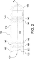
- the body 110 has an inner cavity 160, into which the artificial light source 120 is arranged to direct the produced light ( FIGURES 2 and 3 ).
- the inner cavity 160 runs from the first end of the body 110 to the opposing second end of the body 110.
- optics 130, 140, 150 have been attached to the body 110 for the handling of light rays R1, R2 produced by the artificial light source 120.
- An emission lens 150 has been fitted to the second end of the body 110.
- the emission lens 150 is designed to receive the light produced by the artificial light source 120 and to refract the light into a light pattern suitable for warning about the presence of an obstacle.
- the light pattern is preferably oval, when viewed axially. When installed properly, the obstruction illuminator produces an oval light pattern in the horizontal.
- a toroidal emission lens 150 is used to produce such a light pattern.
- the emission lens 150 receives the artificial light indirectly through an intermediate lens or a series of lenses provided to the inner cavity 160 of the body 110 between the artificial light source 120 and the emission lens 150.
- the obstruction illuminator 100 is installed into place by employing an ancillary device 200, which is designed to supply the obstruction illuminator 100 with power and attachment to the wall 300.
- the ancillary device 200 has a frame 210, which acts as a chassis for connecting the components of the obstruction illuminator assembly 1000 together and on the other hand connecting the obstruction illuminator 100 to the receiving structure, i.e. wall 300.
- the frame 210 may be, for example, a metal plate provided with simple holes for accommodating the attachment to the components of the obstruction illuminator assembly 1000.
- the frame 210 may be attached to the wall 300 by employing various affixers.
- the affixers take the form of magnets 220.
- the wall 300 is made from a ferromagnetic material, such as steel or an alloy comprising steel
- magnets 220 may be attached to the inside surface of the wall 300 and the frame 210 may be attached to the magnets 220 with other affixes, such as screws, rivets, adhesives, etc., or with magnets as well.
- the frame 210 comprises holes, through which screws are dialled into receptive openings on the magnets 220.
- the embodiment of FIGURE 1 makes use of two magnets 220 above and below the obstruction illuminator 100.
- the frame 210 could be attached to the inside surface of the wall 300 by gluing, welding, screwing or otherwise affixing the frame preferably without introducing a through hole to the wall 300. Attachment of the frame 210 with non-intrusive means, such as magnets, is preferred so as to maximize the integrity of the wall 300.
- An attachment spacer 260 is provided to the surface of the frame 210 facing the wall 300.
- the attachment spacer 260 itself may be an integral part of the frame 210 or attached thereto.
- the attachment spacer 260 is dimensioned to fit in the gap between the frame 210 and the wall 300 provided by the magnets 220.
- the obstruction illuminator 100 is connected to the attachment spacer 260 through, for example, a threaded connection between the male thread on the outer surface of the illuminator body 110 and the female thread on hole of the attachment spacer 260, as shown in FIGURE 1 .
- the width of the attachment spacer 260 in the direction of the gap provides for a large contact area between the body 110 and the attachment spacer 260.
- the obstruction illuminator could be attached to a threaded hole on the frame (not shown).
- the illuminator body 110 could be connected to a hole on the frame 210 via an expandable grommet, which may be dialled in to fill the gap between the two components thus affixing them to each other.
- the frame 210 also hosts the power source 250, which may include the control circuits for the obstruction illuminator 100.
- the power source 250 is connected to the obstruction illuminator 100 through a feed cable 230, which runs through the power source enclosure by means of a grommet 240 and terminates to a connector 271 designed to fit a counterpart connector 272 on the obstruction illuminator 100.
- the frame 210 preferably includes a support 280 for supporting the counterpart connector 272 on the obstruction illuminator 100 so as to facilitate easy installation.
- optics 130, 140 are provided into the inner cavity 160 of the illuminator body 110 for manipulating the light output of the artificial light source 120 so as to format the light properly to be emitted by the emission lens 150.
- the optics take the form of an optical condenser element.
- the first end of the body 110 includes the artificial light source 120, which in the illustrated embodiment takes the form of an LED chip.
- the chip receives power from the connector 272, which is presented in FIGURE 1 but omitted from FIGURE 2 for the sake of clarity.
- the LED chip may be, for example, a conventional LED chip producing light in the visible spectrum, particularly exhibiting a red or white colour. Such LED chips are known per se.
- the artificial light source 120 may include a first light emitting element 121, such as an LED chip, producing light in the visible spectrum and a second light emitting element 122, such as an LED chip, producing light in the non-visible spectrum, i.e. spectrum not visible with the naked eye. Accordingly, the first LED 121 may produce red or white light, whereas the second LED 122 may produce infrared light.
- the two light emitting elements 121, 122 may be set into the same circuit board. This embodiment is particularly advantageous because obstruction light is seen also with night vision goggles widely used by various official aircrafts, such as boarder control and military. Unlike traditional halogen illuminators, for example, red or white LEDs do not produce light in an infrared spectrum, which is supplemented with a secondary light emitting element 122.
- a light sensor 160 is provided adjacent to the artificial light source 120 for sensing ambient light through the optics of the obstruction illuminator 100.
- the light sensor 160 may also be set into the same circuit board as the artificial light source 120.
- the light sensor 160 is preferably connected to the control logic circuit of the obstruction illuminator assembly 1000 such that the measurement data of the light sensor 160 is used to switch off the obstruction illuminator 100 in well illuminated conditions, i.e. during day-time.
- the control logic circuit of the obstruction illuminator assembly 1000 may be programmed to briefly switch off the artificial light source 120 to perform the ambient light measurement with the light sensor 160.
- the artificial light source 120 is designed to direct the light into the inner cavity 160 of the body 110, in which cavity 160 the path of the light rays is manipulated with optics, more specifically an optical condenser element.
- FIGURES 2 to 5 show one example of a suitable optical condenser element 130, 140 and the operating principle in greater detail.
- the optics between the artificial light source 120 and the emission lens 150 is formed by an optical condenser element 130, 140, which receives light from the artificial light source 120 and condenses and directs the light toward the emission lens 150.
- the optical condenser element includes a collimator 130 and preferably also an objective 140.
- the collimator 130 and objective 140 may in turn include only one or several light path modifying elements, such as lenses.
- both the collimator 130 and the objective 140 include two lenses 131, 132, 141, 142 each, whereas in FIGURES 4 and 5 , both the collimator 130 and the objective 140 both include only one lens 130', 140', respectively.
- the light is first received by a collimator 130.
- the collimator 130 may be provided with a single lens or, as depicted in FIGURE 2 , the collimator 130 may be established by arranging two successive lenses 131, 132 into the inner cavity 160.
- the solitary lens (not shown) or plurality of lenses 131, 132 may be, for example, Fresnel lenses.
- the purpose of the collimator 130 is to receive light from the artificial light source 120, to condense the received light, and to direct the condensed light toward the emission lens 150 along the inner cavity 160.
- the purpose of the collimator 130 is to realign the light beam produced by the artificial light source 120 to be parallel to the axial dimension of the obstruction illuminator.
- the expression axial refers to the optical axis A o of the emission lens 150 of the illuminator.
- the body 110 of the obstruction illuminator 100 is elongated in the axial dimension. More specifically, the body 110 has a center axis in the major extending dimension thereof.
- the collimator 130 has an optical axis. In the event that the collimator 130 has several lenses, all lenses 131, 132 of the collimator 130 share an optical axis, i.e. the lenses 131, 132 are aligned.
- the center axis of the body 110 and the optical axis of the collimator 130 are co-axial.
- the optical axis A 0 of the emission lens 150 is -albeit parallel - deviated radially from the co-axial axes of the body 110 and the collimator 130 so as to produce a light pattern that is eccentric. The purpose of this is to direct the produced light upward from the obstacle housing the obstruction illuminator 100 such to prevent light from emitting towards the ground.
- the collimator 130 comprises a first lens 131, which produces a first refraction to the artificial light.
- FIGURE 3 shows how the first lens 131 contracts the opening angle of the light beam by sketching the path of two light rays, namely a first light ray R1 and a second light ray R2, which represent the peripheral light rays of a produced artificial light beam.
- the produced light beam is quite wide, i.e. the artificial light source 120 produces a light beam that has several light rays that have an emitting direction with a considerable component deviating from the axial dimension of the emission lens 150. To direct as much light as possible to the emission lens 150, the produced wide light beam is shaped by the collimator 130.
- the first lens 131 refracts the light rays R1, R2 emitting in a direction, which has a large component deviating from the axial dimension of the emission lens 150 to emit closer to the axial dimension of the emission lens 150.
- the second lens 132 of the collimator 130 further refracts the light so as to mitigate components of direction of the light rays R1, R2 deviating from the axial dimension of the lenses 131, 132.
- two lenses 131, 132 are arranged sequentially so as to perform two sequential refractions to redirect the light to emit parallel to the optical axis A o of the emission lens 150.
- the light outputted by the collimator 130 is preferably aligned to emit in a direction parallel or at least as parallel as possible in respect to the optical axis A o of the emission lens 150.
- the outputted light is then received by an objective 140.
- One may foresee an embodiment including more than two lenses arranged sequentially for the same purpose.
- the optical condenser element preferably also includes an objective 140.
- the purpose of the objective 140 is the opposite of that of the collimator 130; to direct or preferably focus the light to the focal point FP of the emission lens 150.
- the objective 140 may include a single lens or a plurality of successively arranged lenses. In the embodiment depicted in FIGURES 2 and 3 the objective 140 includes two lenses 141, 142 arranged successively along the optical axis A o of the emission lens 150.
- the solitary lens (not shown) or plurality of lenses 141, 142 of the objective 140 may be, for example, Fresnel lenses.
- the first lens 141 of the objective 140 refracts the collimated light towards the optical axis A o of the emission lens 150, wherein the light beam is contracted.
- the successive second lens 142 performs a second refraction guiding the light even more towards the focal point FP of the emission lens 150.
- the two lenses 141, 142 of the objective 140 are arranged sequentially so as to perform two sequential refractions to redirect the light to emit towards the focal point FP of the emission lens 150.
- the objective 140 also has an optical axis. In the event that the objective 140 has several lenses, all lenses 141, 142 of the objective 130 share an optical axis, i.e. the lenses 141, 142 are aligned. In the embodiment of FIGURE 2 , the center axis of the body 110 and the optical axis of the collimator 130 and the objective 140 are co-axial. However, the optical axis A 0 of the emission lens 150 is - albeit parallel - deviated radially from the co-axial axes of the body 110, collimator 130 and objective 140 so as to produce a light pattern that is eccentric. The purpose of this is to direct the produced light upward from the obstacle housing the obstruction illuminator 100 such to prevent light from emitting towards the ground.
- the outer dimension of the obstruction illuminator 110 may be minimized compared to deviating a symmetric emission lens from the center axis of the body (not shown) and/or deviating the objective and/or collimator from the center axis of the body (not shown).
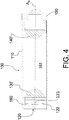
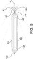
- FIGURES 4 and 5 show an alternative embodiment, wherein the collimator 130 and objective 140 each include only a solitary lens 130', 140', respectively.
- the solitary lenses 130', 140' are aspherical so as to minimize stray light rays from missing the focal point FP of the emission lens 150.
- the aspherical lens 130' of the collimator 130 and the aspherical lens 140' of the objective 140' are reversed such that the light rays arriving from and being emitted to the light source 120 and emission lens 150, respectively, refract through substantially planar optical surfaces, wherein the collimator 130 and objective 140 communicate with each other through curvilinear optical surfaces.
- the single lens embodiment of FIGURES 4 and 5 is similar to that of the double lens embodiment of FIGURES 2 and 3 .
- the substantially planar optical surface of the lens 130' of the collimator 130 refracts the light rays R1, R2 emitting in a direction, which has a large component deviating from the axial dimension of the emission lens 150 to emit closer to the axial dimension of the emission lens 150.
- the curvilinear optical surface of the lens 130' further refracts the light so as to mitigate components of direction of the light rays R1, R2 deviating from the axial dimension of lens 130'.
- the two optical surfaces of the aspherical lens 130' are arranged sequentially so as to perform two sequential refractions to redirect the light to emit parallel to the optical axis A o of the emission lens 150.
- the light outputted by the collimator 130 is preferably aligned to emit in a direction parallel or at least as parallel as possible in respect to the optical axis A o of the emission lens 150.
- the reversed occurs at the objective.
- the curvilinear optical surface of the lens 140' refracts the collimated light towards the optical axis A o of the emission lens 150, wherein the light beam is contracted.
- the successive substantially planar optical surface of the lens 140' performs a second refraction guiding the light even more towards the focal point FP of the emission lens 150.
- the two optical surfaces of the lens 140' are arranged sequentially so as to perform two sequential refractions to redirect the light to emit towards the focal point FP of the emission lens 150
- FIGURES 2 and 3 it is possible to combine the embodiments of FIGURES 2 and 3 as well as 4 and 5.
- the dual-lens collimator 130 or objective 140 of FIGURES 2 and 3 may be replaced with a single lens collimator 130 or objective 140 of FIGURES 4 and 5 , respectively, or with any alternative non-illustrated embodiment described above.
- the majority of the light produced by the artificial light source 120 is preferably collected at the focal point FP of the emission lens 150.
- the artificial light source 120 may be created virtually at the focal point FP of the emission lens 150. Accordingly, the construction enables the light source to the provided to the rear of the obstruction illuminator 100.
- the emission lens 150 may be a typical output lens used in connection with obstruction illuminators. Accordingly, the emission lens 150 is adapted to produce a suitable light distribution for obstruction lighting purposes. Such lenses are known per se.
Landscapes
- Engineering & Computer Science (AREA)
- General Engineering & Computer Science (AREA)
- Power Engineering (AREA)
- Non-Portable Lighting Devices Or Systems Thereof (AREA)
Abstract
Description
- The present invention relates to warning signals. In particular, the invention relates to emitting visual signals so as to issue a warning about an obstacle, such as a tall building or a wind mill. More specifically, the present invention relates to an obstruction illuminator, obstruction illuminator assembly and installation method according to the preamble portions of claims 1, 19 and 20, respectively.
- Obstruction illuminators or 'obstacle lights' are widely used to mark tall or otherwise prominent constructions so as to warn aviators and navigators about the presence of an obstruction, which must be avoided. Wind power plants, for example, are so tall that they must be marked with a particular illuminated marker, which must conform to a host of regulatory standards. Indeed, a variety of different obstruction illuminators have been created for wind power plants that comply with strict requirements for the shape and intensity of the emitted light pattern.
- The obstruction illuminators installed in wind power plants, for example, are exposed to harsh weather conditions, such as fluctuating and extreme temperatures, lightning, etc. In addition, the installation of the illuminators is challenging because the installation takes place quite high above ground.
WO 2006/077084 A1 discloses a solution to address installation by proposing a rod-like illuminator, which is installed from inside the tower of a wind power plant through a hole, wherein the light source is located at the end of the rod-like body of the illuminator so as to extend from the tower emit light to the environment. However, the delicate light source is thus exposed to the elements, which not only strains the LED chip but also requires a robust in terms of insulation distance etc.EP 1544460 A2 , on the other hand, discloses an alternative design, in which the artificial light source is placed inside the tower to be protected from the elements. While this approach is robust, it suffers from difficult installation because the emission lens must be installed outside the tower. - Accordingly, there is a need to achieve a proper light distribution pattern with a robust obstruction illuminator that is easy to install.
- A novel obstruction illuminator is therefore herein proposed. The obstruction illuminator features an elongated body with a first end and a second end opposing the first end. The body of the obstruction illuminator has an inner cavity, which extends between the first and second end. An artificial light source is fitted to the first end of the body and an emission lens is fitted to the second end of the body. The artificial light source is configured to emit light into the cavity towards the second end. An optical condenser element is provided into the inner cavity of the body between the artificial light source and the emission lens. The optical condenser element receives light from the artificial light source as well as condenses and directs the condensed light toward the emission lens. The emission lens refracts the light into a pattern suitable for warning about the presence of an obstacle.
- An obstruction illuminator assembly is also proposed for a similar purpose. The novel assembly includes the above described obstruction illuminator to a frame, which also hosts a power source which feeds power to the obstruction illuminator.
- A method for installing an obstruction illuminator to a receiving structure, such as a wall of a wind turbine tower, is further proposed. In the method, the above described obstruction illuminator is provided and inserted from the inner volume of the enclosing structure through an opening in the structure to at least partially outside the structure. The obstruction illuminator is then secured to the structure.
- The invention is defined by the features of the independent claims. Some specific embodiments are defined in the dependent claims.
- Considerable benefits are gained with aid of the novel obstruction illuminator. By virtue of the novel design, the obstruction illuminator may be installed to the receiving structure from the inside, which is particularly advantageous in difficult to reach structures, such as wind turbines, tall buildings, such as bridges, etc. By positioning the artificial light source to the end of the elongated obstruction illuminator, which on the inside of or within the opening in the receiving structure, the artificial light source is protected from the ambient, e.g. lightning, by the receiving structure. In addition, location inside the receiving structure provides the freedom to include large protective components to further protect the electronics of the device, e.g. the light source. On the other hand, the artificial light source may be easily replaced from inside the structure. The collimator within the hollow obstruction illuminator body, on the other hand, provides for an effective use of the lighting power of the artificial light source. The collimator in other words enables the manipulation of the light produced by the artificial light source to be effectively guided towards the emission lens, whereby the obstruction illuminator may be built with a relatively small emission lens thus enabling installation through insertion from the inside. Such an optical arrangement enables the construction of rather long illuminators, e.g. with a body length of 15 cm, that protrude prominently from the receiving structure without compromising the light output of the device. A long body also enables use in thin steel walls and thick concrete walls alike thus expanding the versatility of the device.
- In the following, certain embodiments of the invention are described in greater detail with reference to the accompanying drawings, in which:
- FIGURE 1
- illustrates a cut-out view of an installed obstruction illuminator in accordance with at least some embodiments of the present invention;
- FIGURE 2
- illustrates a simplified and isolated cut-out view of the obstruction illuminator of
FIGURE 1 ; - FIGURE 3
- illustrates light ray diagram showing the passage of light rays in the obstruction illuminator of
FIGURE 2 ; - FIGURE 4
- illustrates a simplified and isolated cut-out view of an obstruction illuminator according to another embodiment, and
- FIGURE 5
- illustrates light ray diagram showing the passage of light rays in the obstruction illuminator of
FIGURE 4 . - An
obstruction illuminator 100 as part of anobstruction illuminator assembly 1000, which includes theilluminator 100 and anancillary device 200 therefore, is herein disclosed. As shown inFIGURE 1 , anobstruction illuminator 100 according to one embodiment is to be installed to a receivingstructure 300 of a tall building, e.g. a wall of a wind turbine, bridge, sky scraper, observation tower, etc., from the inside. While there may be foreseen several other applications, the present disclosure will refer to the structure as a wind turbine wall as an example. Thewall 300 comprises an opening, such as a bore, for receiving the illuminator from the inside through thewall 300. No other accommodations are necessary albeit possible. Theobstruction illuminator 100 has anelongated body 110, which is designed to be inserted from the inside through the opening in thewall 300 so as to extend to the ambient space outside thewall 300. At one end of thebody 110, i.e. the first end, anartificial light source 120 has been fitted. When installed, theartificial light source 120 will preferably remain on the inside of thewall 300 or partly enclosed by the opening in the wall (not shown) so as to protect theartificial light source 120 from the environment outside thewall 300. - The
body 110 has aninner cavity 160, into which theartificial light source 120 is arranged to direct the produced light (FIGURES 2 and3 ). Theinner cavity 160 runs from the first end of thebody 110 to the opposing second end of thebody 110. Generally speaking,optics body 110 for the handling of light rays R1, R2 produced by theartificial light source 120. Anemission lens 150 has been fitted to the second end of thebody 110. Theemission lens 150 is designed to receive the light produced by the artificiallight source 120 and to refract the light into a light pattern suitable for warning about the presence of an obstacle. The light pattern is preferably oval, when viewed axially. When installed properly, the obstruction illuminator produces an oval light pattern in the horizontal. According to one embodiment, atoroidal emission lens 150 is used to produce such a light pattern. As will become apparent here after from the disclosure in connection toFIGURES 2 and3 , theemission lens 150 receives the artificial light indirectly through an intermediate lens or a series of lenses provided to theinner cavity 160 of thebody 110 between the artificiallight source 120 and theemission lens 150. - Returning back to
FIGURE 1 it is pointed out that theobstruction illuminator 100 is installed into place by employing anancillary device 200, which is designed to supply theobstruction illuminator 100 with power and attachment to thewall 300. Let us first consider attachment. Theancillary device 200 has aframe 210, which acts as a chassis for connecting the components of theobstruction illuminator assembly 1000 together and on the other hand connecting theobstruction illuminator 100 to the receiving structure, i.e.wall 300. Theframe 210 may be, for example, a metal plate provided with simple holes for accommodating the attachment to the components of theobstruction illuminator assembly 1000. - The
frame 210 may be attached to thewall 300 by employing various affixers. In the illustrated embodiment, the affixers take the form ofmagnets 220. If thewall 300 is made from a ferromagnetic material, such as steel or an alloy comprising steel,magnets 220 may be attached to the inside surface of thewall 300 and theframe 210 may be attached to themagnets 220 with other affixes, such as screws, rivets, adhesives, etc., or with magnets as well. In the embodiment shown inFIGURE 1 , theframe 210 comprises holes, through which screws are dialled into receptive openings on themagnets 220. The embodiment ofFIGURE 1 makes use of twomagnets 220 above and below theobstruction illuminator 100. However, more of fewer magnets are foreseeable. Alternatively (not shown), theframe 210 could be attached to the inside surface of thewall 300 by gluing, welding, screwing or otherwise affixing the frame preferably without introducing a through hole to thewall 300. Attachment of theframe 210 with non-intrusive means, such as magnets, is preferred so as to maximize the integrity of thewall 300. - An
attachment spacer 260 is provided to the surface of theframe 210 facing thewall 300. Theattachment spacer 260 itself may be an integral part of theframe 210 or attached thereto. Theattachment spacer 260 is dimensioned to fit in the gap between theframe 210 and thewall 300 provided by themagnets 220. Theobstruction illuminator 100 is connected to theattachment spacer 260 through, for example, a threaded connection between the male thread on the outer surface of theilluminator body 110 and the female thread on hole of theattachment spacer 260, as shown inFIGURE 1 . The width of theattachment spacer 260 in the direction of the gap provides for a large contact area between thebody 110 and theattachment spacer 260. Alternatively, the obstruction illuminator could be attached to a threaded hole on the frame (not shown). According to yet another alternative (not shown), theilluminator body 110 could be connected to a hole on theframe 210 via an expandable grommet, which may be dialled in to fill the gap between the two components thus affixing them to each other. - The
frame 210 also hosts thepower source 250, which may include the control circuits for theobstruction illuminator 100. Thepower source 250 is connected to theobstruction illuminator 100 through afeed cable 230, which runs through the power source enclosure by means of agrommet 240 and terminates to aconnector 271 designed to fit acounterpart connector 272 on theobstruction illuminator 100. Theframe 210 preferably includes asupport 280 for supporting thecounterpart connector 272 on theobstruction illuminator 100 so as to facilitate easy installation. - As shown in
FIGURE 1 ,optics inner cavity 160 of theilluminator body 110 for manipulating the light output of the artificiallight source 120 so as to format the light properly to be emitted by theemission lens 150. In the present disclosure the optics take the form of an optical condenser element. As may be seen, the first end of thebody 110 includes the artificiallight source 120, which in the illustrated embodiment takes the form of an LED chip. The chip receives power from theconnector 272, which is presented inFIGURE 1 but omitted fromFIGURE 2 for the sake of clarity. The LED chip may be, for example, a conventional LED chip producing light in the visible spectrum, particularly exhibiting a red or white colour. Such LED chips are known per se. According to a further embodiment shown in detail inFIGURE 2 , the artificiallight source 120 may include a firstlight emitting element 121, such as an LED chip, producing light in the visible spectrum and a secondlight emitting element 122, such as an LED chip, producing light in the non-visible spectrum, i.e. spectrum not visible with the naked eye. Accordingly, thefirst LED 121 may produce red or white light, whereas thesecond LED 122 may produce infrared light. The twolight emitting elements light emitting element 122. - According to a further embodiment, a
light sensor 160 is provided adjacent to the artificiallight source 120 for sensing ambient light through the optics of theobstruction illuminator 100. Thelight sensor 160 may also be set into the same circuit board as the artificiallight source 120. Thelight sensor 160 is preferably connected to the control logic circuit of theobstruction illuminator assembly 1000 such that the measurement data of thelight sensor 160 is used to switch off theobstruction illuminator 100 in well illuminated conditions, i.e. during day-time. For this purpose the control logic circuit of theobstruction illuminator assembly 1000 may be programmed to briefly switch off the artificiallight source 120 to perform the ambient light measurement with thelight sensor 160. - The artificial
light source 120 is designed to direct the light into theinner cavity 160 of thebody 110, in whichcavity 160 the path of the light rays is manipulated with optics, more specifically an optical condenser element.FIGURES 2 to 5 show one example of a suitableoptical condenser element light source 120 and theemission lens 150 is formed by anoptical condenser element light source 120 and condenses and directs the light toward theemission lens 150. The optical condenser element includes acollimator 130 and preferably also an objective 140. Thecollimator 130 and objective 140 may in turn include only one or several light path modifying elements, such as lenses. InFIGURES 2 and3 , both thecollimator 130 and the objective 140 include twolenses FIGURES 4 and5 , both thecollimator 130 and the objective 140 both include only onelens 130', 140', respectively. - Let us first consider the embodiment of
FIGURE 2 . The light is first received by acollimator 130. Thecollimator 130 may be provided with a single lens or, as depicted inFIGURE 2 , thecollimator 130 may be established by arranging twosuccessive lenses inner cavity 160. The solitary lens (not shown) or plurality oflenses collimator 130 is to receive light from the artificiallight source 120, to condense the received light, and to direct the condensed light toward theemission lens 150 along theinner cavity 160. In other words, the purpose of thecollimator 130 is to realign the light beam produced by the artificiallight source 120 to be parallel to the axial dimension of the obstruction illuminator. In this context, the expression axial refers to the optical axis Ao of theemission lens 150 of the illuminator. In the shown embodiment thebody 110 of theobstruction illuminator 100 is elongated in the axial dimension. More specifically, thebody 110 has a center axis in the major extending dimension thereof. On the other hand, thecollimator 130 has an optical axis. In the event that thecollimator 130 has several lenses, alllenses collimator 130 share an optical axis, i.e. thelenses FIGURE 2 , the center axis of thebody 110 and the optical axis of thecollimator 130 are co-axial. However, the optical axis A0 of theemission lens 150 is -albeit parallel - deviated radially from the co-axial axes of thebody 110 and thecollimator 130 so as to produce a light pattern that is eccentric. The purpose of this is to direct the produced light upward from the obstacle housing theobstruction illuminator 100 such to prevent light from emitting towards the ground. - In the illustrated embodiment the
collimator 130 comprises afirst lens 131, which produces a first refraction to the artificial light.FIGURE 3 shows how thefirst lens 131 contracts the opening angle of the light beam by sketching the path of two light rays, namely a first light ray R1 and a second light ray R2, which represent the peripheral light rays of a produced artificial light beam. The produced light beam is quite wide, i.e. the artificiallight source 120 produces a light beam that has several light rays that have an emitting direction with a considerable component deviating from the axial dimension of theemission lens 150. To direct as much light as possible to theemission lens 150, the produced wide light beam is shaped by thecollimator 130. Thefirst lens 131 refracts the light rays R1, R2 emitting in a direction, which has a large component deviating from the axial dimension of theemission lens 150 to emit closer to the axial dimension of theemission lens 150. Thesecond lens 132 of thecollimator 130 further refracts the light so as to mitigate components of direction of the light rays R1, R2 deviating from the axial dimension of thelenses lenses emission lens 150. The light outputted by thecollimator 130 is preferably aligned to emit in a direction parallel or at least as parallel as possible in respect to the optical axis Ao of theemission lens 150. The outputted light is then received by an objective 140. One may foresee an embodiment including more than two lenses arranged sequentially for the same purpose. - As mentioned above, the optical condenser element preferably also includes an objective 140. The purpose of the objective 140 is the opposite of that of the
collimator 130; to direct or preferably focus the light to the focal point FP of theemission lens 150. The objective 140 may include a single lens or a plurality of successively arranged lenses. In the embodiment depicted inFIGURES 2 and3 theobjective 140 includes twolenses emission lens 150. The solitary lens (not shown) or plurality oflenses first lens 141 of the objective 140 refracts the collimated light towards the optical axis Ao of theemission lens 150, wherein the light beam is contracted. The successivesecond lens 142 performs a second refraction guiding the light even more towards the focal point FP of theemission lens 150. In other words, the twolenses emission lens 150. One may foresee an embodiment including more than two lenses arranged sequentially for the same purpose. - The objective 140 also has an optical axis. In the event that the objective 140 has several lenses, all
lenses lenses FIGURE 2 , the center axis of thebody 110 and the optical axis of thecollimator 130 and the objective 140 are co-axial. However, the optical axis A0 of theemission lens 150 is - albeit parallel - deviated radially from the co-axial axes of thebody 110,collimator 130 and objective 140 so as to produce a light pattern that is eccentric. The purpose of this is to direct the produced light upward from the obstacle housing theobstruction illuminator 100 such to prevent light from emitting towards the ground. On the other hand, by making theemission lens 150 eccentric, the outer dimension of theobstruction illuminator 110 may be minimized compared to deviating a symmetric emission lens from the center axis of the body (not shown) and/or deviating the objective and/or collimator from the center axis of the body (not shown). -
FIGURES 4 and5 show an alternative embodiment, wherein thecollimator 130 and objective 140 each include only asolitary lens 130', 140', respectively. In the illustrated embodiment thesolitary lenses 130', 140' are aspherical so as to minimize stray light rays from missing the focal point FP of theemission lens 150. As may be seen fromFIGURE 5 , the aspherical lens 130' of thecollimator 130 and theaspherical lens 140' of the objective 140' are reversed such that the light rays arriving from and being emitted to thelight source 120 andemission lens 150, respectively, refract through substantially planar optical surfaces, wherein thecollimator 130 and objective 140 communicate with each other through curvilinear optical surfaces. - As concerns the manipulation of light rays R1, R2, the single lens embodiment of
FIGURES 4 and5 is similar to that of the double lens embodiment ofFIGURES 2 and3 . The substantially planar optical surface of the lens 130' of thecollimator 130 refracts the light rays R1, R2 emitting in a direction, which has a large component deviating from the axial dimension of theemission lens 150 to emit closer to the axial dimension of theemission lens 150. The curvilinear optical surface of the lens 130' further refracts the light so as to mitigate components of direction of the light rays R1, R2 deviating from the axial dimension of lens 130'. In other words, the two optical surfaces of the aspherical lens 130' are arranged sequentially so as to perform two sequential refractions to redirect the light to emit parallel to the optical axis Ao of theemission lens 150. The light outputted by thecollimator 130 is preferably aligned to emit in a direction parallel or at least as parallel as possible in respect to the optical axis Ao of theemission lens 150. - The reversed occurs at the objective. The curvilinear optical surface of the
lens 140' refracts the collimated light towards the optical axis Ao of theemission lens 150, wherein the light beam is contracted. The successive substantially planar optical surface of thelens 140' performs a second refraction guiding the light even more towards the focal point FP of theemission lens 150. In other words, the two optical surfaces of thelens 140' are arranged sequentially so as to perform two sequential refractions to redirect the light to emit towards the focal point FP of theemission lens 150 - Furthermore, it is possible to combine the embodiments of
FIGURES 2 and3 as well as 4 and 5. In other words, the dual-lens collimator 130 orobjective 140 ofFIGURES 2 and3 may be replaced with asingle lens collimator 130 orobjective 140 ofFIGURES 4 and5 , respectively, or with any alternative non-illustrated embodiment described above. - When properly set up, the majority of the light produced by the artificial
light source 120 is preferably collected at the focal point FP of theemission lens 150. By arranging thecollimator 130 adjacent the artificiallight source 120 and the objective 140 adjacent theemission lens 150, the artificiallight source 120 may be created virtually at the focal point FP of theemission lens 150. Accordingly, the construction enables the light source to the provided to the rear of theobstruction illuminator 100. Theemission lens 150 may be a typical output lens used in connection with obstruction illuminators. Accordingly, theemission lens 150 is adapted to produce a suitable light distribution for obstruction lighting purposes. Such lenses are known per se. - It is to be understood that the embodiments of the invention disclosed are not limited to the particular structures, process steps, or materials disclosed herein, but are extended to equivalents thereof as would be recognized by those ordinarily skilled in the relevant arts. It should also be understood that terminology employed herein is used for the purpose of describing particular embodiments only and is not intended to be limiting.
- Reference throughout this specification to one embodiment or an embodiment means that a particular feature, structure, or characteristic described in connection with the embodiment is included in at least one embodiment of the present invention. Thus, appearances of the phrases "in one embodiment" or "in an embodiment" in various places throughout this specification are not necessarily all referring to the same embodiment. Where reference is made to a numerical value using a term such as, for example, about or substantially, the exact numerical value is also disclosed.
- As used herein, a plurality of items, structural elements, compositional elements, and/or materials may be presented in a common list for convenience. However, these lists should be construed as though each member of the list is individually identified as a separate and unique member. Thus, no individual member of such list should be construed as a de facto equivalent of any other member of the same list solely based on their presentation in a common group without indications to the contrary. In addition, various embodiments and example of the present invention may be referred to herein along with alternatives for the various components thereof. It is understood that such embodiments, examples, and alternatives are not to be construed as de facto equivalents of one another, but are to be considered as separate and autonomous representations of the present invention.
- Furthermore, the described features, structures, or characteristics may be combined in any suitable manner in one or more embodiments. In this description, numerous specific details are provided, such as examples of lengths, widths, shapes, etc., to provide a thorough understanding of embodiments of the invention. One skilled in the relevant art will recognize, however, that the invention can be practiced without one or more of the specific details, or with other methods, components, materials, etc. In other instances, well-known structures, materials, or operations are not shown or described in detail to avoid obscuring aspects of the invention.
- While the forgoing examples are illustrative of the principles of the present invention in one or more particular applications, it will be apparent to those of ordinary skill in the art that numerous modifications in form, usage and details of implementation can be made without the exercise of inventive faculty, and without departing from the principles and concepts of the invention. Accordingly, it is not intended that the invention be limited, except as by the claims set forth below.
- The verbs "to comprise" and "to include" are used in this document as open limitations that neither exclude nor require the existence of also un-recited features. The features recited in depending claims are mutually freely combinable unless otherwise explicitly stated. Furthermore, it is to be understood that the use of "a" or "an", that is, a singular form, throughout this document does not exclude a plurality.
-
No. Part No. Part 100 obstruction illuminator 200 ancillary device 110 body 210 frame 120 artificial light source 220 magnet 121 first light emitting element 230 cable 122 second light emitting element 240 grommet 130 collimator 250 power source 130' aspherical lens 260 attachment spacer 131 first lens 271 connector 132 second lens 272 counterpart connector 140 objective 280 support 140' aspherical lens 300 structure, e.g. wall 141 first lens 1000 obstruction illuminator assembly 142 second lens FP focal point 150 emission lens R1 first ray of light 160 light sensor R2 second ray of light -
- Patent Literature
-
WO 2006/077084 A1 -
EP 1544460 A2
Claims (20)
- An obstruction illuminator (100) comprising:- an elongated body (110) having a first end and a second end opposing the first end,- an artificial light source (120) attached to the first end of the body (110) and- an emission lens (150), which is:characterized in that:o provided to the second end of the body (110),o configured to receive light emitted by the artificial light source (120), ando configured to refract light into a light pattern suitable for warning about the presence of an obstacle,- the body (110) comprises an inner cavity (160) extending between the first and second end, wherein the artificial light source (120) is configured to emit light into the cavity (160) towards the second end, and in that- the obstruction illuminator (100) comprises an optical condenser element (130, 140) provided into the inner cavity (160) of the body (100) between the artificial light source (120) and the emission lens (150), which optical condenser element (130, 140) is configured to:∘ receive light from the artificial light source (120),∘ condense the received light, and to∘ direct the condensed light toward the emission lens (150).
- The obstruction illuminator (100) according to claim 1, wherein the optical condenser element (130, 140) comprises a collimator (130).
- The obstruction illuminator (100) according to claim 2, wherein the collimator (130) is configured to collimate the light produced by the artificial light source to emit in a direction parallel to the optical axis (Ao) of the emission lens (150).
- The obstruction illuminator (100) according to claim 2 or 3, wherein the collimator (130) comprises two lenses (131, 132) arranged sequentially so as to perform two sequential refractions to redirect the light to emit in a direction parallel to the optical axis (Ao) of the emission lens (150).
- The obstruction illuminator (100) according to any of the preceding claims, wherein the lenses (131, 132) are Fresnel lenses.
- The obstruction illuminator (100) according to claim 2 or 3, wherein the collimator comprises an aspherical lens (130').
- The obstruction illuminator (100) according to any of the preceding claims 2 to 6, wherein the optical condenser element (130, 140) comprises an objective (140) arranged between the collimator (130) and the emission lens (150) and configured to receive the collimated light from the collimator (130) and to direct the light to the emission lens (150).
- The obstruction illuminator (100) according to claim 7, wherein the objective (140) is configured to focus the light into the focal point (FP) of the emission lens (150).
- The obstruction illuminator (100) according to claim 7 or 8, wherein the objective (140) is closer to the emission lens (150) than to the collimator (130).
- The obstruction illuminator (100) according to claim 7, 8 or 9, wherein the objective (140) comprises two lenses (141, 142) arranged sequentially so as to perform two sequential refractions to redirect the light to emit towards the focal point (FP) of the emission lens (150).
- The obstruction illuminator (100) according to claim 10, wherein the lenses (141, 142) are Fresnel lenses.
- The obstruction illuminator (100) according to claim 7, 8 or 9, wherein the objective comprises an aspherical lens (140').
- The obstruction illuminator (100) according to any of the preceding claims, wherein the emission lens (150) is a toroidal lens.
- The obstruction illuminator (100) according to any of the preceding claims, wherein the emission lens (150) is configured to produce an oval light pattern, when viewed axially.
- The obstruction illuminator (100) according to any of the preceding claims, wherein the obstruction illuminator (100) comprises a terminal (272) arranged to the first end of the body (110) for supplying power to the artificial light source (120).
- The obstruction illuminator (100) according to any of the preceding claims, wherein the artificial light source (120) comprises a first light emitting element (121) emitting light in the visible spectrum and a second light emitting element (122) emitting light in the non-visible spectrum.
- The obstruction illuminator (100) according to any of the preceding claims, wherein a light sensor (160) provided adjacent to the artificial light source (120) and configured to sense ambient light through the optics of the obstruction illuminator (100).
- The obstruction illuminator (100) according to any of the preceding claims 7 to 15, wherein:- the body (110) comprises a center axis extending along the main dimension of extension of the body (110),- the collimator (130) comprises an optical axis,- the objective (140) comprises an optical axis,- the optical axes of the collimator (130) and the objective (140) as well as the center axis of the body (110) are co-axial,- the optical axis (Ao) of the emission lens (150) is radially translated from the co-axial optical or center axes of the collimator (130), objective (140) and body (110), respectively, and wherein- the emission lens (150) is eccentric in respect to the optical axis (Ao) thereof.
- An obstruction illuminator assembly (1000) comprising:- a frame (210),- an obstruction illuminator (100) attached to the frame (210), and- a power source (250) attached to the frame (210) and configured to feed power to the obstruction illuminator (100),characterized in that the obstruction illuminator (100) is such defined by any of the preceding claims.
- A method for installing an obstruction illuminator (100) to a receiving structure (300) having enclosing an inner volume, the method comprising the steps of:- providing an obstruction illuminator (100) according to any of the preceding claims 1 to 18,- inserting the obstruction illuminator (100) from the inner volume of the enclosing structure (300) through an opening in the structure (300) to at least partially outside the structure, and- securing the obstruction illuminator (100) to the structure (300).
Priority Applications (4)
| Application Number | Priority Date | Filing Date | Title |
|---|---|---|---|
| DK16205223T DK3339722T5 (en) | 2016-12-20 | 2016-12-20 | OBSTRUCTION ILLUMINATOR, OBSTRUCTION ILLUMINATOR DEVICE AND INSTALLATION PROCEDURE |
| EP16205223.7A EP3339722B1 (en) | 2016-12-20 | 2016-12-20 | Obstruction illuminator, obstruction illuminator assembly and installation method |
| US16/470,561 US11226080B2 (en) | 2016-12-20 | 2017-12-20 | Obstruction illuminator, obstruction illuminator assembly and installation method |
| PCT/FI2017/050919 WO2018115587A1 (en) | 2016-12-20 | 2017-12-20 | Obstruction illuminator, obstruction illuminator assembly and installation method |
Applications Claiming Priority (1)
| Application Number | Priority Date | Filing Date | Title |
|---|---|---|---|
| EP16205223.7A EP3339722B1 (en) | 2016-12-20 | 2016-12-20 | Obstruction illuminator, obstruction illuminator assembly and installation method |
Publications (2)
| Publication Number | Publication Date |
|---|---|
| EP3339722A1 true EP3339722A1 (en) | 2018-06-27 |
| EP3339722B1 EP3339722B1 (en) | 2019-08-14 |
Family
ID=57629336
Family Applications (1)
| Application Number | Title | Priority Date | Filing Date |
|---|---|---|---|
| EP16205223.7A Active EP3339722B1 (en) | 2016-12-20 | 2016-12-20 | Obstruction illuminator, obstruction illuminator assembly and installation method |
Country Status (4)
| Country | Link |
|---|---|
| US (1) | US11226080B2 (en) |
| EP (1) | EP3339722B1 (en) |
| DK (1) | DK3339722T5 (en) |
| WO (1) | WO2018115587A1 (en) |
Cited By (1)
| Publication number | Priority date | Publication date | Assignee | Title |
|---|---|---|---|---|
| US11434874B2 (en) * | 2017-02-22 | 2022-09-06 | Siemens Gamesa Renewable Energy A/S | Tower for a wind turbine and a wind turbine |
Citations (10)
| Publication number | Priority date | Publication date | Assignee | Title |
|---|---|---|---|---|
| US4084215A (en) * | 1977-02-25 | 1978-04-11 | The United States Of America As Represented By The Secretary Of The Navy | Strobe light having reduced electromagnetic radiation |
| US6249375B1 (en) * | 1998-01-19 | 2001-06-19 | Swarco Futurit Verkehrssignal Systeme Ges M.B.H. | Optical element for traffic signs, display panels or the like |
| EP1544460A2 (en) | 2003-12-15 | 2005-06-22 | REpower Systems AG | Wind power plant comprising a flight obstacle light |
| WO2006077084A1 (en) | 2005-01-19 | 2006-07-27 | Aloys Wobben | Rod-shaped light for marking a tower with lights |
| US20070053203A1 (en) * | 2004-03-27 | 2007-03-08 | Morton Graham | Illumination device |
| EP2112424A1 (en) * | 2008-04-25 | 2009-10-28 | emz-Hanauer GmbH & Co. KGaA | Light emitting device for a domestic appliance |
| EP2213876A1 (en) * | 2009-02-03 | 2010-08-04 | Siemens Aktiengesellschaft | Tower, in particular for a wind turbine |
| WO2014047983A1 (en) * | 2012-09-18 | 2014-04-03 | 天津天星电子有限公司 | Three-dimensionally irradiating reflector-lamp and method |
| US20140252249A1 (en) * | 2011-07-13 | 2014-09-11 | Doros Teodora - D.A.Glass | Method of obtaining a uniform beam of electromagnetic radiation of arbitrary geometrical shape and a mechanical-optical device for applications of this method |
| DE102013110857A1 (en) * | 2013-10-01 | 2015-04-02 | Quantec Networks Gmbh | Beacon for firing a wind turbine, in particular a tower of a wind turbine |
Family Cites Families (9)
| Publication number | Priority date | Publication date | Assignee | Title |
|---|---|---|---|---|
| US4681414A (en) * | 1983-06-09 | 1987-07-21 | Hershel Ronald S | Condenser system |
| US5774088A (en) * | 1994-07-26 | 1998-06-30 | The University Of Pittsburgh | Method and system for warning birds of hazards |
| JP2003043580A (en) * | 2001-07-30 | 2003-02-13 | Mitsubishi Electric Corp | Lamp, polarization conversion optical system and image display device |
| CA2660423A1 (en) * | 2006-08-10 | 2008-02-14 | Upstream Engineering Oy | Illuminator method and device |
| US20080101067A1 (en) * | 2006-10-31 | 2008-05-01 | Dante Cariboni | LED lighting device |
| US8651695B2 (en) * | 2010-03-26 | 2014-02-18 | Excelitas Technologies Corp. | LED based high-intensity light with secondary diffuser |
| US9080751B2 (en) * | 2011-09-17 | 2015-07-14 | Diane Michelle Steele | Outdoor solar lamp with a base having flat and pointed foot elements |
| CA2949845C (en) * | 2015-12-04 | 2020-10-13 | AGM Automotive, LLC | Illumination device for projecting light in a predetermined illumination pattern on a surface |
| WO2017136442A1 (en) * | 2016-02-01 | 2017-08-10 | Jay S. Orringer, M.D., A Professional Corporation | Wireless surgical headlight |
-
2016
- 2016-12-20 EP EP16205223.7A patent/EP3339722B1/en active Active
- 2016-12-20 DK DK16205223T patent/DK3339722T5/en active
-
2017
- 2017-12-20 WO PCT/FI2017/050919 patent/WO2018115587A1/en not_active Ceased
- 2017-12-20 US US16/470,561 patent/US11226080B2/en active Active
Patent Citations (10)
| Publication number | Priority date | Publication date | Assignee | Title |
|---|---|---|---|---|
| US4084215A (en) * | 1977-02-25 | 1978-04-11 | The United States Of America As Represented By The Secretary Of The Navy | Strobe light having reduced electromagnetic radiation |
| US6249375B1 (en) * | 1998-01-19 | 2001-06-19 | Swarco Futurit Verkehrssignal Systeme Ges M.B.H. | Optical element for traffic signs, display panels or the like |
| EP1544460A2 (en) | 2003-12-15 | 2005-06-22 | REpower Systems AG | Wind power plant comprising a flight obstacle light |
| US20070053203A1 (en) * | 2004-03-27 | 2007-03-08 | Morton Graham | Illumination device |
| WO2006077084A1 (en) | 2005-01-19 | 2006-07-27 | Aloys Wobben | Rod-shaped light for marking a tower with lights |
| EP2112424A1 (en) * | 2008-04-25 | 2009-10-28 | emz-Hanauer GmbH & Co. KGaA | Light emitting device for a domestic appliance |
| EP2213876A1 (en) * | 2009-02-03 | 2010-08-04 | Siemens Aktiengesellschaft | Tower, in particular for a wind turbine |
| US20140252249A1 (en) * | 2011-07-13 | 2014-09-11 | Doros Teodora - D.A.Glass | Method of obtaining a uniform beam of electromagnetic radiation of arbitrary geometrical shape and a mechanical-optical device for applications of this method |
| WO2014047983A1 (en) * | 2012-09-18 | 2014-04-03 | 天津天星电子有限公司 | Three-dimensionally irradiating reflector-lamp and method |
| DE102013110857A1 (en) * | 2013-10-01 | 2015-04-02 | Quantec Networks Gmbh | Beacon for firing a wind turbine, in particular a tower of a wind turbine |
Cited By (1)
| Publication number | Priority date | Publication date | Assignee | Title |
|---|---|---|---|---|
| US11434874B2 (en) * | 2017-02-22 | 2022-09-06 | Siemens Gamesa Renewable Energy A/S | Tower for a wind turbine and a wind turbine |
Also Published As
| Publication number | Publication date |
|---|---|
| EP3339722B1 (en) | 2019-08-14 |
| DK3339722T3 (en) | 2019-10-21 |
| US20190338914A1 (en) | 2019-11-07 |
| WO2018115587A1 (en) | 2018-06-28 |
| US11226080B2 (en) | 2022-01-18 |
| DK3339722T5 (en) | 2019-10-28 |
Similar Documents
| Publication | Publication Date | Title |
|---|---|---|
| RU2547648C2 (en) | Finder system | |
| US10386157B2 (en) | Illuminated sight system | |
| US8459822B1 (en) | Multiple laser sighting and illumination systems for firearms | |
| AT500056B8 (en) | OPTIC ELEMENT FOR TRAFFIC SIGNS, INDICATOR TABLES OR DGL. | |
| WO2004038286A3 (en) | A deployable airfield luminaire | |
| ES2464141T3 (en) | Optical representation element as well as representation device | |
| EP3086024A3 (en) | Light emitting module | |
| EP2572990A1 (en) | Aircraft light for emitting light in a desired spatial angular region and with a desired light distribution | |
| EP2632166A3 (en) | System to test performance of pixels in a sensor array | |
| EP2476992A3 (en) | Fiber optic shotgun sight | |
| CA2595250A1 (en) | Rod-shaped light for marking a tower with lights | |
| EP1710493A3 (en) | Vitual point light source | |
| AU2018246128B2 (en) | Through wall lighting | |
| WO2010107537A3 (en) | High efficiency optical coupler | |
| EP3339722B1 (en) | Obstruction illuminator, obstruction illuminator assembly and installation method | |
| KR20230166161A (en) | Aviation obstacle lights with multi-functional luminous module | |
| EP1918159A3 (en) | Lighting device for vehicle and door mirror device | |
| EP3640533B1 (en) | Lens, illuminator, and omnidirectional illuminating system | |
| DE102013110857A1 (en) | Beacon for firing a wind turbine, in particular a tower of a wind turbine | |
| CN206960756U (en) | Integrated target for the debugging of multispectral optoelectronic device light path coaxial | |
| EP3074805B1 (en) | Lighting device | |
| TW200721554A (en) | Light source with light emitting array and collection optic | |
| DE602006019620D1 (en) | Inset flash fire | |
| TW200636214A (en) | Method for improving display brightness of laser rangefinder | |
| SE0101063D0 (en) | A system for singling a sliding simulator and a singling unit for this system |
Legal Events
| Date | Code | Title | Description |
|---|---|---|---|
| PUAI | Public reference made under article 153(3) epc to a published international application that has entered the european phase |
Free format text: ORIGINAL CODE: 0009012 |
|
| STAA | Information on the status of an ep patent application or granted ep patent |
Free format text: STATUS: THE APPLICATION HAS BEEN PUBLISHED |
|
| AK | Designated contracting states |
Kind code of ref document: A1 Designated state(s): AL AT BE BG CH CY CZ DE DK EE ES FI FR GB GR HR HU IE IS IT LI LT LU LV MC MK MT NL NO PL PT RO RS SE SI SK SM TR |
|
| AX | Request for extension of the european patent |
Extension state: BA ME |
|
| STAA | Information on the status of an ep patent application or granted ep patent |
Free format text: STATUS: REQUEST FOR EXAMINATION WAS MADE |
|
| 17P | Request for examination filed |
Effective date: 20181231 |
|
| RBV | Designated contracting states (corrected) |
Designated state(s): AL AT BE BG CH CY CZ DE DK EE ES FI FR GB GR HR HU IE IS IT LI LT LU LV MC MK MT NL NO PL PT RO RS SE SI SK SM TR |
|
| RIC1 | Information provided on ipc code assigned before grant |
Ipc: F21V 5/04 20060101ALN20190417BHEP Ipc: F21W 111/00 20060101ALN20190417BHEP Ipc: F21V 5/00 20180101AFI20190417BHEP Ipc: F21Y 113/00 20160101ALN20190417BHEP Ipc: F21V 23/04 20060101ALN20190417BHEP Ipc: F21Y 115/10 20160101ALN20190417BHEP |
|
| GRAP | Despatch of communication of intention to grant a patent |
Free format text: ORIGINAL CODE: EPIDOSNIGR1 |
|
| STAA | Information on the status of an ep patent application or granted ep patent |
Free format text: STATUS: GRANT OF PATENT IS INTENDED |
|
| INTG | Intention to grant announced |
Effective date: 20190613 |
|
| RIC1 | Information provided on ipc code assigned before grant |
Ipc: F21Y 113/00 20160101ALN20190603BHEP Ipc: F21V 23/04 20060101ALN20190603BHEP Ipc: F21V 5/04 20060101ALN20190603BHEP Ipc: F21W 111/00 20060101ALN20190603BHEP Ipc: F21V 5/00 20180101AFI20190603BHEP Ipc: F21Y 115/10 20160101ALN20190603BHEP |
|
| GRAS | Grant fee paid |
Free format text: ORIGINAL CODE: EPIDOSNIGR3 |
|
| GRAA | (expected) grant |
Free format text: ORIGINAL CODE: 0009210 |
|
| STAA | Information on the status of an ep patent application or granted ep patent |
Free format text: STATUS: THE PATENT HAS BEEN GRANTED |
|
| AK | Designated contracting states |
Kind code of ref document: B1 Designated state(s): AL AT BE BG CH CY CZ DE DK EE ES FI FR GB GR HR HU IE IS IT LI LT LU LV MC MK MT NL NO PL PT RO RS SE SI SK SM TR |
|
| REG | Reference to a national code |
Ref country code: GB Ref legal event code: FG4D |
|
| REG | Reference to a national code |
Ref country code: CH Ref legal event code: EP Ref country code: AT Ref legal event code: REF Ref document number: 1167458 Country of ref document: AT Kind code of ref document: T Effective date: 20190815 |
|
| REG | Reference to a national code |
Ref country code: IE Ref legal event code: FG4D |
|
| REG | Reference to a national code |
Ref country code: DE Ref legal event code: R096 Ref document number: 602016018528 Country of ref document: DE |
|
| REG | Reference to a national code |
Ref country code: DK Ref legal event code: T3 Effective date: 20191017 |
|
| REG | Reference to a national code |
Ref country code: DK Ref legal event code: T5 Effective date: 20191024 |
|
| REG | Reference to a national code |
Ref country code: NL Ref legal event code: FP |
|
| REG | Reference to a national code |
Ref country code: LT Ref legal event code: MG4D |
|
| PG25 | Lapsed in a contracting state [announced via postgrant information from national office to epo] |
Ref country code: LT Free format text: LAPSE BECAUSE OF FAILURE TO SUBMIT A TRANSLATION OF THE DESCRIPTION OR TO PAY THE FEE WITHIN THE PRESCRIBED TIME-LIMIT Effective date: 20190814 Ref country code: HR Free format text: LAPSE BECAUSE OF FAILURE TO SUBMIT A TRANSLATION OF THE DESCRIPTION OR TO PAY THE FEE WITHIN THE PRESCRIBED TIME-LIMIT Effective date: 20190814 Ref country code: SE Free format text: LAPSE BECAUSE OF FAILURE TO SUBMIT A TRANSLATION OF THE DESCRIPTION OR TO PAY THE FEE WITHIN THE PRESCRIBED TIME-LIMIT Effective date: 20190814 Ref country code: BG Free format text: LAPSE BECAUSE OF FAILURE TO SUBMIT A TRANSLATION OF THE DESCRIPTION OR TO PAY THE FEE WITHIN THE PRESCRIBED TIME-LIMIT Effective date: 20191114 Ref country code: NO Free format text: LAPSE BECAUSE OF FAILURE TO SUBMIT A TRANSLATION OF THE DESCRIPTION OR TO PAY THE FEE WITHIN THE PRESCRIBED TIME-LIMIT Effective date: 20191114 Ref country code: FI Free format text: LAPSE BECAUSE OF FAILURE TO SUBMIT A TRANSLATION OF THE DESCRIPTION OR TO PAY THE FEE WITHIN THE PRESCRIBED TIME-LIMIT Effective date: 20190814 Ref country code: PT Free format text: LAPSE BECAUSE OF FAILURE TO SUBMIT A TRANSLATION OF THE DESCRIPTION OR TO PAY THE FEE WITHIN THE PRESCRIBED TIME-LIMIT Effective date: 20191216 |
|
| REG | Reference to a national code |
Ref country code: AT Ref legal event code: MK05 Ref document number: 1167458 Country of ref document: AT Kind code of ref document: T Effective date: 20190814 |
|
| PG25 | Lapsed in a contracting state [announced via postgrant information from national office to epo] |
Ref country code: IS Free format text: LAPSE BECAUSE OF FAILURE TO SUBMIT A TRANSLATION OF THE DESCRIPTION OR TO PAY THE FEE WITHIN THE PRESCRIBED TIME-LIMIT Effective date: 20191214 Ref country code: RS Free format text: LAPSE BECAUSE OF FAILURE TO SUBMIT A TRANSLATION OF THE DESCRIPTION OR TO PAY THE FEE WITHIN THE PRESCRIBED TIME-LIMIT Effective date: 20190814 Ref country code: LV Free format text: LAPSE BECAUSE OF FAILURE TO SUBMIT A TRANSLATION OF THE DESCRIPTION OR TO PAY THE FEE WITHIN THE PRESCRIBED TIME-LIMIT Effective date: 20190814 Ref country code: GR Free format text: LAPSE BECAUSE OF FAILURE TO SUBMIT A TRANSLATION OF THE DESCRIPTION OR TO PAY THE FEE WITHIN THE PRESCRIBED TIME-LIMIT Effective date: 20191115 Ref country code: AL Free format text: LAPSE BECAUSE OF FAILURE TO SUBMIT A TRANSLATION OF THE DESCRIPTION OR TO PAY THE FEE WITHIN THE PRESCRIBED TIME-LIMIT Effective date: 20190814 Ref country code: ES Free format text: LAPSE BECAUSE OF FAILURE TO SUBMIT A TRANSLATION OF THE DESCRIPTION OR TO PAY THE FEE WITHIN THE PRESCRIBED TIME-LIMIT Effective date: 20190814 |
|
| PG25 | Lapsed in a contracting state [announced via postgrant information from national office to epo] |
Ref country code: TR Free format text: LAPSE BECAUSE OF FAILURE TO SUBMIT A TRANSLATION OF THE DESCRIPTION OR TO PAY THE FEE WITHIN THE PRESCRIBED TIME-LIMIT Effective date: 20190814 |
|
| PG25 | Lapsed in a contracting state [announced via postgrant information from national office to epo] |
Ref country code: AT Free format text: LAPSE BECAUSE OF FAILURE TO SUBMIT A TRANSLATION OF THE DESCRIPTION OR TO PAY THE FEE WITHIN THE PRESCRIBED TIME-LIMIT Effective date: 20190814 Ref country code: PL Free format text: LAPSE BECAUSE OF FAILURE TO SUBMIT A TRANSLATION OF THE DESCRIPTION OR TO PAY THE FEE WITHIN THE PRESCRIBED TIME-LIMIT Effective date: 20190814 Ref country code: RO Free format text: LAPSE BECAUSE OF FAILURE TO SUBMIT A TRANSLATION OF THE DESCRIPTION OR TO PAY THE FEE WITHIN THE PRESCRIBED TIME-LIMIT Effective date: 20190814 Ref country code: EE Free format text: LAPSE BECAUSE OF FAILURE TO SUBMIT A TRANSLATION OF THE DESCRIPTION OR TO PAY THE FEE WITHIN THE PRESCRIBED TIME-LIMIT Effective date: 20190814 |
|
| PG25 | Lapsed in a contracting state [announced via postgrant information from national office to epo] |
Ref country code: SM Free format text: LAPSE BECAUSE OF FAILURE TO SUBMIT A TRANSLATION OF THE DESCRIPTION OR TO PAY THE FEE WITHIN THE PRESCRIBED TIME-LIMIT Effective date: 20190814 Ref country code: CZ Free format text: LAPSE BECAUSE OF FAILURE TO SUBMIT A TRANSLATION OF THE DESCRIPTION OR TO PAY THE FEE WITHIN THE PRESCRIBED TIME-LIMIT Effective date: 20190814 Ref country code: SK Free format text: LAPSE BECAUSE OF FAILURE TO SUBMIT A TRANSLATION OF THE DESCRIPTION OR TO PAY THE FEE WITHIN THE PRESCRIBED TIME-LIMIT Effective date: 20190814 Ref country code: IS Free format text: LAPSE BECAUSE OF FAILURE TO SUBMIT A TRANSLATION OF THE DESCRIPTION OR TO PAY THE FEE WITHIN THE PRESCRIBED TIME-LIMIT Effective date: 20200224 |
|
| REG | Reference to a national code |
Ref country code: DE Ref legal event code: R097 Ref document number: 602016018528 Country of ref document: DE |
|
| PLBE | No opposition filed within time limit |
Free format text: ORIGINAL CODE: 0009261 |
|
| STAA | Information on the status of an ep patent application or granted ep patent |
Free format text: STATUS: NO OPPOSITION FILED WITHIN TIME LIMIT |
|
| PG2D | Information on lapse in contracting state deleted |
Ref country code: IS |
|
| REG | Reference to a national code |
Ref country code: CH Ref legal event code: PL |
|
| 26N | No opposition filed |
Effective date: 20200603 |
|
| REG | Reference to a national code |
Ref country code: BE Ref legal event code: MM Effective date: 20191231 |
|
| PG25 | Lapsed in a contracting state [announced via postgrant information from national office to epo] |
Ref country code: SI Free format text: LAPSE BECAUSE OF FAILURE TO SUBMIT A TRANSLATION OF THE DESCRIPTION OR TO PAY THE FEE WITHIN THE PRESCRIBED TIME-LIMIT Effective date: 20190814 Ref country code: MC Free format text: LAPSE BECAUSE OF FAILURE TO SUBMIT A TRANSLATION OF THE DESCRIPTION OR TO PAY THE FEE WITHIN THE PRESCRIBED TIME-LIMIT Effective date: 20190814 |
|
| PG25 | Lapsed in a contracting state [announced via postgrant information from national office to epo] |
Ref country code: IE Free format text: LAPSE BECAUSE OF NON-PAYMENT OF DUE FEES Effective date: 20191220 Ref country code: LU Free format text: LAPSE BECAUSE OF NON-PAYMENT OF DUE FEES Effective date: 20191220 |
|
| PG25 | Lapsed in a contracting state [announced via postgrant information from national office to epo] |
Ref country code: LI Free format text: LAPSE BECAUSE OF NON-PAYMENT OF DUE FEES Effective date: 20191231 Ref country code: CH Free format text: LAPSE BECAUSE OF NON-PAYMENT OF DUE FEES Effective date: 20191231 Ref country code: BE Free format text: LAPSE BECAUSE OF NON-PAYMENT OF DUE FEES Effective date: 20191231 |
|
| PG25 | Lapsed in a contracting state [announced via postgrant information from national office to epo] |
Ref country code: CY Free format text: LAPSE BECAUSE OF FAILURE TO SUBMIT A TRANSLATION OF THE DESCRIPTION OR TO PAY THE FEE WITHIN THE PRESCRIBED TIME-LIMIT Effective date: 20190814 |
|
| PG25 | Lapsed in a contracting state [announced via postgrant information from national office to epo] |
Ref country code: MT Free format text: LAPSE BECAUSE OF FAILURE TO SUBMIT A TRANSLATION OF THE DESCRIPTION OR TO PAY THE FEE WITHIN THE PRESCRIBED TIME-LIMIT Effective date: 20190814 Ref country code: HU Free format text: LAPSE BECAUSE OF FAILURE TO SUBMIT A TRANSLATION OF THE DESCRIPTION OR TO PAY THE FEE WITHIN THE PRESCRIBED TIME-LIMIT; INVALID AB INITIO Effective date: 20161220 |
|
| GBPC | Gb: european patent ceased through non-payment of renewal fee |
Effective date: 20201220 |
|
| PG25 | Lapsed in a contracting state [announced via postgrant information from national office to epo] |
Ref country code: GB Free format text: LAPSE BECAUSE OF NON-PAYMENT OF DUE FEES Effective date: 20201220 |
|
| PG25 | Lapsed in a contracting state [announced via postgrant information from national office to epo] |
Ref country code: MK Free format text: LAPSE BECAUSE OF FAILURE TO SUBMIT A TRANSLATION OF THE DESCRIPTION OR TO PAY THE FEE WITHIN THE PRESCRIBED TIME-LIMIT Effective date: 20190814 |
|
| PGFP | Annual fee paid to national office [announced via postgrant information from national office to epo] |
Ref country code: DE Payment date: 20251211 Year of fee payment: 10 |
|
| PGFP | Annual fee paid to national office [announced via postgrant information from national office to epo] |
Ref country code: IT Payment date: 20251223 Year of fee payment: 10 Ref country code: DK Payment date: 20251224 Year of fee payment: 10 |
|
| PGFP | Annual fee paid to national office [announced via postgrant information from national office to epo] |
Ref country code: FR Payment date: 20251229 Year of fee payment: 10 Ref country code: NL Payment date: 20251219 Year of fee payment: 10 |