EP3339707A1 - A hose for connection to a gas cylinder - Google Patents
A hose for connection to a gas cylinder Download PDFInfo
- Publication number
- EP3339707A1 EP3339707A1 EP17208603.5A EP17208603A EP3339707A1 EP 3339707 A1 EP3339707 A1 EP 3339707A1 EP 17208603 A EP17208603 A EP 17208603A EP 3339707 A1 EP3339707 A1 EP 3339707A1
- Authority
- EP
- European Patent Office
- Prior art keywords
- hose
- nut
- gas
- cylinder
- detect
- Prior art date
- Legal status (The legal status is an assumption and is not a legal conclusion. Google has not performed a legal analysis and makes no representation as to the accuracy of the status listed.)
- Withdrawn
Links
- 230000033001 locomotion Effects 0.000 claims abstract description 17
- 239000007789 gas Substances 0.000 description 16
- 230000000694 effects Effects 0.000 description 2
- 239000002184 metal Substances 0.000 description 2
- 230000005540 biological transmission Effects 0.000 description 1
- 238000001514 detection method Methods 0.000 description 1
- 229940075473 medical gases Drugs 0.000 description 1
- 238000000034 method Methods 0.000 description 1
- 230000004048 modification Effects 0.000 description 1
- 238000012986 modification Methods 0.000 description 1
- 230000003287 optical effect Effects 0.000 description 1
Images
Classifications
-
- G—PHYSICS
- G01—MEASURING; TESTING
- G01P—MEASURING LINEAR OR ANGULAR SPEED, ACCELERATION, DECELERATION, OR SHOCK; INDICATING PRESENCE, ABSENCE, OR DIRECTION, OF MOVEMENT
- G01P13/00—Indicating or recording presence, absence, or direction, of movement
-
- F—MECHANICAL ENGINEERING; LIGHTING; HEATING; WEAPONS; BLASTING
- F16—ENGINEERING ELEMENTS AND UNITS; GENERAL MEASURES FOR PRODUCING AND MAINTAINING EFFECTIVE FUNCTIONING OF MACHINES OR INSTALLATIONS; THERMAL INSULATION IN GENERAL
- F16L—PIPES; JOINTS OR FITTINGS FOR PIPES; SUPPORTS FOR PIPES, CABLES OR PROTECTIVE TUBING; MEANS FOR THERMAL INSULATION IN GENERAL
- F16L11/00—Hoses, i.e. flexible pipes
-
- F—MECHANICAL ENGINEERING; LIGHTING; HEATING; WEAPONS; BLASTING
- F16—ENGINEERING ELEMENTS AND UNITS; GENERAL MEASURES FOR PRODUCING AND MAINTAINING EFFECTIVE FUNCTIONING OF MACHINES OR INSTALLATIONS; THERMAL INSULATION IN GENERAL
- F16L—PIPES; JOINTS OR FITTINGS FOR PIPES; SUPPORTS FOR PIPES, CABLES OR PROTECTIVE TUBING; MEANS FOR THERMAL INSULATION IN GENERAL
- F16L35/00—Special arrangements used in connection with end fittings of hoses, e.g. safety or protecting devices
-
- G—PHYSICS
- G01—MEASURING; TESTING
- G01B—MEASURING LENGTH, THICKNESS OR SIMILAR LINEAR DIMENSIONS; MEASURING ANGLES; MEASURING AREAS; MEASURING IRREGULARITIES OF SURFACES OR CONTOURS
- G01B21/00—Measuring arrangements or details thereof, where the measuring technique is not covered by the other groups of this subclass, unspecified or not relevant
- G01B21/22—Measuring arrangements or details thereof, where the measuring technique is not covered by the other groups of this subclass, unspecified or not relevant for measuring angles or tapers; for testing the alignment of axes
-
- G—PHYSICS
- G01—MEASURING; TESTING
- G01B—MEASURING LENGTH, THICKNESS OR SIMILAR LINEAR DIMENSIONS; MEASURING ANGLES; MEASURING AREAS; MEASURING IRREGULARITIES OF SURFACES OR CONTOURS
- G01B7/00—Measuring arrangements characterised by the use of electric or magnetic techniques
-
- G—PHYSICS
- G01—MEASURING; TESTING
- G01D—MEASURING NOT SPECIALLY ADAPTED FOR A SPECIFIC VARIABLE; ARRANGEMENTS FOR MEASURING TWO OR MORE VARIABLES NOT COVERED IN A SINGLE OTHER SUBCLASS; TARIFF METERING APPARATUS; MEASURING OR TESTING NOT OTHERWISE PROVIDED FOR
- G01D5/00—Mechanical means for transferring the output of a sensing member; Means for converting the output of a sensing member to another variable where the form or nature of the sensing member does not constrain the means for converting; Transducers not specially adapted for a specific variable
- G01D5/26—Mechanical means for transferring the output of a sensing member; Means for converting the output of a sensing member to another variable where the form or nature of the sensing member does not constrain the means for converting; Transducers not specially adapted for a specific variable characterised by optical transfer means, i.e. using infrared, visible, or ultraviolet light
- G01D5/39—Scanning a visible indication of the measured value and reproducing this indication at the remote place, e.g. on the screen of a cathode ray tube
-
- F—MECHANICAL ENGINEERING; LIGHTING; HEATING; WEAPONS; BLASTING
- F16—ENGINEERING ELEMENTS AND UNITS; GENERAL MEASURES FOR PRODUCING AND MAINTAINING EFFECTIVE FUNCTIONING OF MACHINES OR INSTALLATIONS; THERMAL INSULATION IN GENERAL
- F16L—PIPES; JOINTS OR FITTINGS FOR PIPES; SUPPORTS FOR PIPES, CABLES OR PROTECTIVE TUBING; MEANS FOR THERMAL INSULATION IN GENERAL
- F16L19/00—Joints in which sealing surfaces are pressed together by means of a member, e.g. a swivel nut, screwed on, or into, one of the joint parts
- F16L19/02—Pipe ends provided with collars or flanges, integral with the pipe or not, pressed together by a screwed member
- F16L19/025—Pipe ends provided with collars or flanges, integral with the pipe or not, pressed together by a screwed member the pipe ends having integral collars or flanges
-
- F—MECHANICAL ENGINEERING; LIGHTING; HEATING; WEAPONS; BLASTING
- F16—ENGINEERING ELEMENTS AND UNITS; GENERAL MEASURES FOR PRODUCING AND MAINTAINING EFFECTIVE FUNCTIONING OF MACHINES OR INSTALLATIONS; THERMAL INSULATION IN GENERAL
- F16L—PIPES; JOINTS OR FITTINGS FOR PIPES; SUPPORTS FOR PIPES, CABLES OR PROTECTIVE TUBING; MEANS FOR THERMAL INSULATION IN GENERAL
- F16L2201/00—Special arrangements for pipe couplings
- F16L2201/10—Indicators for correct coupling
-
- F—MECHANICAL ENGINEERING; LIGHTING; HEATING; WEAPONS; BLASTING
- F16—ENGINEERING ELEMENTS AND UNITS; GENERAL MEASURES FOR PRODUCING AND MAINTAINING EFFECTIVE FUNCTIONING OF MACHINES OR INSTALLATIONS; THERMAL INSULATION IN GENERAL
- F16L—PIPES; JOINTS OR FITTINGS FOR PIPES; SUPPORTS FOR PIPES, CABLES OR PROTECTIVE TUBING; MEANS FOR THERMAL INSULATION IN GENERAL
- F16L2201/00—Special arrangements for pipe couplings
- F16L2201/20—Safety or protective couplings
-
- F—MECHANICAL ENGINEERING; LIGHTING; HEATING; WEAPONS; BLASTING
- F16—ENGINEERING ELEMENTS AND UNITS; GENERAL MEASURES FOR PRODUCING AND MAINTAINING EFFECTIVE FUNCTIONING OF MACHINES OR INSTALLATIONS; THERMAL INSULATION IN GENERAL
- F16L—PIPES; JOINTS OR FITTINGS FOR PIPES; SUPPORTS FOR PIPES, CABLES OR PROTECTIVE TUBING; MEANS FOR THERMAL INSULATION IN GENERAL
- F16L2201/00—Special arrangements for pipe couplings
- F16L2201/60—Identification or marking
-
- F—MECHANICAL ENGINEERING; LIGHTING; HEATING; WEAPONS; BLASTING
- F17—STORING OR DISTRIBUTING GASES OR LIQUIDS
- F17C—VESSELS FOR CONTAINING OR STORING COMPRESSED, LIQUEFIED OR SOLIDIFIED GASES; FIXED-CAPACITY GAS-HOLDERS; FILLING VESSELS WITH, OR DISCHARGING FROM VESSELS, COMPRESSED, LIQUEFIED, OR SOLIDIFIED GASES
- F17C2205/00—Vessel construction, in particular mounting arrangements, attachments or identifications means
- F17C2205/03—Fluid connections, filters, valves, closure means or other attachments
- F17C2205/0302—Fittings, valves, filters, or components in connection with the gas storage device
- F17C2205/0352—Pipes
- F17C2205/0364—Pipes flexible or articulated, e.g. a hose
-
- F—MECHANICAL ENGINEERING; LIGHTING; HEATING; WEAPONS; BLASTING
- F17—STORING OR DISTRIBUTING GASES OR LIQUIDS
- F17C—VESSELS FOR CONTAINING OR STORING COMPRESSED, LIQUEFIED OR SOLIDIFIED GASES; FIXED-CAPACITY GAS-HOLDERS; FILLING VESSELS WITH, OR DISCHARGING FROM VESSELS, COMPRESSED, LIQUEFIED, OR SOLIDIFIED GASES
- F17C2205/00—Vessel construction, in particular mounting arrangements, attachments or identifications means
- F17C2205/05—Vessel or content identifications, e.g. labels
- F17C2205/055—Vessel or content identifications, e.g. labels by magnetic means
-
- F—MECHANICAL ENGINEERING; LIGHTING; HEATING; WEAPONS; BLASTING
- F17—STORING OR DISTRIBUTING GASES OR LIQUIDS
- F17C—VESSELS FOR CONTAINING OR STORING COMPRESSED, LIQUEFIED OR SOLIDIFIED GASES; FIXED-CAPACITY GAS-HOLDERS; FILLING VESSELS WITH, OR DISCHARGING FROM VESSELS, COMPRESSED, LIQUEFIED, OR SOLIDIFIED GASES
- F17C2205/00—Vessel construction, in particular mounting arrangements, attachments or identifications means
- F17C2205/05—Vessel or content identifications, e.g. labels
- F17C2205/058—Vessel or content identifications, e.g. labels by Radio Frequency Identification
-
- F—MECHANICAL ENGINEERING; LIGHTING; HEATING; WEAPONS; BLASTING
- F17—STORING OR DISTRIBUTING GASES OR LIQUIDS
- F17C—VESSELS FOR CONTAINING OR STORING COMPRESSED, LIQUEFIED OR SOLIDIFIED GASES; FIXED-CAPACITY GAS-HOLDERS; FILLING VESSELS WITH, OR DISCHARGING FROM VESSELS, COMPRESSED, LIQUEFIED, OR SOLIDIFIED GASES
- F17C2250/00—Accessories; Control means; Indicating, measuring or monitoring of parameters
- F17C2250/04—Indicating or measuring of parameters as input values
- F17C2250/0404—Parameters indicated or measured
- F17C2250/0482—Acceleration
-
- F—MECHANICAL ENGINEERING; LIGHTING; HEATING; WEAPONS; BLASTING
- F17—STORING OR DISTRIBUTING GASES OR LIQUIDS
- F17C—VESSELS FOR CONTAINING OR STORING COMPRESSED, LIQUEFIED OR SOLIDIFIED GASES; FIXED-CAPACITY GAS-HOLDERS; FILLING VESSELS WITH, OR DISCHARGING FROM VESSELS, COMPRESSED, LIQUEFIED, OR SOLIDIFIED GASES
- F17C2270/00—Applications
- F17C2270/02—Applications for medical applications
Definitions
- the present invention relates to a hose for connection to a gas cylinder.
- Gas cylinders are portable freestanding devices which are delivered to various sites for the supply of, for example, industrial and medical gases to locations where no mains gas supply is available. Because of the nature of these cylinders, they are often supplied in advance to the end user who may have little or no experience in fitting the cylinders to the gas consuming equipment.
- multiple gas hoses are connected to a gas manifold which receives gas supplies from more than one cylinder. If a hose has not been connected to one port of the manifold, this can provide a vent path for cylinders connected to other ports of the manifold. This is at best wasteful and at worst dangerous if there is an uncontrolled leak of gas.
- the connectors are designed such that they will not dispense gas until the connection is properly made. However, it is still useful to know that the hose is correctly connected to ensure continuity of gas supply to the gas consuming equipment.
- a hose according to claim 1 According to a first aspect of the present invention, there is provided a hose according to claim 1.
- the motion sensor which detects movement of the first end and/or the nut allows the detection of an event associated with connecting and/or disconnecting the hose providing useful information on the state of connection of the hose to the cylinder.
- the motion sensor may be an accelerometer. This may be set up to sense, for example, a change of angle of the first end of the hose. Sensing the change of angle is characteristic of disconnection of the hose from the cylinder resulting in an abrupt drop. The subsequent angle of the end indicates that the end has been reconnected. Alternatively or additionally the sensor may be configured to sense vibrations caused by rotation of the nut. This demonstrates that the nut has been unscrewed or screwed.
- the sensor may be a detectable tag provided on the nut.
- the detectable tag may, for example, be a hall sensor to detect a passing magnetic field. Alternatively it may be a light sensor to sense a passing pattern. In either case, the sensor may be on the nut with the component to be sensed being on the hose, or these two components may be arranged the other way around.
- the motion sensor is configured to detect the passing of the tag as the nut is rotated. This provides direct sensing of the rotation of the nut and therefore determines that the nut has been screwed or unscrewed.
- the tag may not need to be capable of detecting the direction of rotation.
- the tag may be configured to sense the direction of rotation. For example, if the tag is made up of two or more elements generating different electronic signals, the order of receipt of these signals at the sensor provides an indication of the direction of rotation.
- the hose may be connected directly to the cylinder.
- the hose may be connected to the cylinder via a regulator.
- the hose may additionally or alternatively be connected to the cylinder via a manifold to which a number of other hoses are connected.
- the manifold has a plurality of inlet ports via one of which the hose is connected to the cylinder.
- the invention also extends to a system comprising a hose according to the first aspect of the present invention together with a remote unit, the remote unit having a receiver to receive signals from the transmitter, the remote unit being programmed with at least one predetermined signal characteristic of a particular movement of the first end of the hose and/or nut and a controller to compare the received signal against the predetermined signal characteristic to detect a particular movement condition.
- the receiver is configured to receive signals from the transmitters of more than one of the hoses.
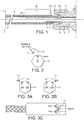
- FIG. 1 is a schematic cross-section through the hose connected to a cylinder and remote unit
- the cylinder 1 is a standard gas cylinder provided with a gas outlet 2 with a screw threaded connection 3.
- the invention is specifically designed to connect to standard cylinders without modification so that no further description of the cylinder will be provided here. It should be noted, however, that the invention could also be applied to a cylinder with a female screw thread.
- the hose 5 is again a standard component with a flexible connection between the cylinder 1 and a first end 6 and gas consuming equipment 7 at a second end 8.
- the connector at the first end 6 is made up of two main components, namely an insert 9 and a screw threaded nut 10.
- the insert 9 is inserted into the first end 6 of the hose 5 and has a number of ridges 11 to enhance the interference fit with the hose.
- a crimp connection ensures a gas tight seal between the hose 5 and insert 9.
- the end of the insert 9 which protrudes from the tube 5 has a flange 13 which is sealed to the end of the outlet 2 by metal to metal seal.
- the connection is secured by the nut 10 which has a screw thread 15 which mates with the screw thread 3 on the outlet 2.
- the opposite end of the nut 10 bears against the flange 13 to tighten the flange onto the outlet 2.
- this is a conventional way of attaching a hose to a cylinder.
- the improvement provided by the present invention is the provision of the sensor 20.
- the sensor may be attached to any part of the connection in the vicinity of the first end 6. As shown here, it is attached to the hose 5 but could also be attached to the insert 9 or the nut 10.
- the nut 10 is provided with an electronically detectable tag 21 such as a magnet, RFID tag, distinctive marking or the like and the sensor 20 is configured to detect the passing of the tag 21 as the nut 10 is rotated.
- Fig. 2 depicts the tag 21 as a distinctive marking on the back of the nut which is detected by an optical sensor 23 on the nut 10 (shown schematically in Fig. 2 ) as the nut 10 rotates past the markings.
- there are two distinctive markings spaced in close proximity around the nut so that rotation in one directed can be distinguished from rotation in the opposite direction depending on the order of sensing of the two tags 21.
- Fig. 3A to 3C An alternative is shown in Fig. 3A to 3C .
- the tag 21 is a magnet and there are a pair of hall sensors 24 providing the sensor 20.
- the sensor 24B will pass the magnet 21 shortly before the sensor 24A.
- Rotation in the opposite direction shown in Fig. 3B will cause the opposite effect in that the sensor 24A will pass the magnet 21 shortly before the sensor 24B allowing a controller to determine the direction of rotation.
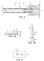
- FIG. 4 A further alternative is shown in Fig. 4 .
- the sensor 20 is provided by an accelerometer 31.
- the accelerometer 31 In the normally connected configuration depicted in Fig. 4A , the accelerometer 31 is in a horizontal configuration. When the nut 10 is disconnected, because the hose 5 is unsupported, it will move to a generally vertical configuration as shown in Fig. 4B and the accelerometer is able to detect the movement to the new orientation.
- the accelerometer 31 shown in Fig. 4 may be replaced by a vibration sensor.
- the vibration sensor may be directly on the nut 10 so as to sense the motion of the nut 10 directly.
- the information detected by the sensor 20 is transmitted via a transmitter 25 using any known form of data transmission to a remote unit 40 comprising a receiver 41 and a controller 42.
- the remote unit 40 may be a bespoke unit, or may be a smart phone, tablet or remote computer terminal.
- the receiver 41 receives the signal from the sensor 20 and the controller 42 compares the received signal with a database containing information regarding characteristic signals indicative of various conditions concerning the attachment and reattachment of the nut 10 as set out above.
- the controller 42 can therefore determine whether the nut 10 has been detached and/or reattached. This information can simply be logged for later diagnostic access. Alternatively or additionally it can be used to sound an alarm to a user or activate some form of safety procedure which will not allow a user to use the gas supply until the correct attachment of the nut 10 can be verified.
Landscapes
- Engineering & Computer Science (AREA)
- General Engineering & Computer Science (AREA)
- Physics & Mathematics (AREA)
- General Physics & Mathematics (AREA)
- Mechanical Engineering (AREA)
- Filling Or Discharging Of Gas Storage Vessels (AREA)
- Pipeline Systems (AREA)
Abstract
Description
- The present invention relates to a hose for connection to a gas cylinder.
- Gas cylinders are portable freestanding devices which are delivered to various sites for the supply of, for example, industrial and medical gases to locations where no mains gas supply is available. Because of the nature of these cylinders, they are often supplied in advance to the end user who may have little or no experience in fitting the cylinders to the gas consuming equipment.
- In some cases, multiple gas hoses are connected to a gas manifold which receives gas supplies from more than one cylinder. If a hose has not been connected to one port of the manifold, this can provide a vent path for cylinders connected to other ports of the manifold. This is at best wasteful and at worst dangerous if there is an uncontrolled leak of gas.
- In the case of a single cylinder, the connectors are designed such that they will not dispense gas until the connection is properly made. However, it is still useful to know that the hose is correctly connected to ensure continuity of gas supply to the gas consuming equipment.
- According to a first aspect of the present invention, there is provided a hose according to claim 1.
- The motion sensor which detects movement of the first end and/or the nut allows the detection of an event associated with connecting and/or disconnecting the hose providing useful information on the state of connection of the hose to the cylinder.
- The motion sensor may be an accelerometer. This may be set up to sense, for example, a change of angle of the first end of the hose. Sensing the change of angle is characteristic of disconnection of the hose from the cylinder resulting in an abrupt drop. The subsequent angle of the end indicates that the end has been reconnected. Alternatively or additionally the sensor may be configured to sense vibrations caused by rotation of the nut. This demonstrates that the nut has been unscrewed or screwed.
- Alternatively or additionally the sensor may be a detectable tag provided on the nut. The detectable tag may, for example, be a hall sensor to detect a passing magnetic field. Alternatively it may be a light sensor to sense a passing pattern. In either case, the sensor may be on the nut with the component to be sensed being on the hose, or these two components may be arranged the other way around. The motion sensor is configured to detect the passing of the tag as the nut is rotated. This provides direct sensing of the rotation of the nut and therefore determines that the nut has been screwed or unscrewed. The tag may not need to be capable of detecting the direction of rotation. It can be assumed that if one set of signals indicating rotation is relatively quickly followed by a second set of signals, that the first represents unscrewing of the nut and the second represents screwing up of the nut. Alternatively, the tag may be configured to sense the direction of rotation. For example, if the tag is made up of two or more elements generating different electronic signals, the order of receipt of these signals at the sensor provides an indication of the direction of rotation.
- The hose may be connected directly to the cylinder. Alternatively, the hose may be connected to the cylinder via a regulator. As a further option, the hose may additionally or alternatively be connected to the cylinder via a manifold to which a number of other hoses are connected. In this instance, preferably, the manifold has a plurality of inlet ports via one of which the hose is connected to the cylinder.
- The invention also extends to a system comprising a hose according to the first aspect of the present invention together with a remote unit, the remote unit having a receiver to receive signals from the transmitter, the remote unit being programmed with at least one predetermined signal characteristic of a particular movement of the first end of the hose and/or nut and a controller to compare the received signal against the predetermined signal characteristic to detect a particular movement condition. In this case, preferably, the receiver is configured to receive signals from the transmitters of more than one of the hoses.
- An example of the present invention will now be described with reference to the accompanying drawings in whichFig. 1 is a schematic cross-section through the hose connected to a cylinder and remote unit;
-
Fig. 2 is a schematic view of a first sensor configuration; -
Figs. 3A to 3C are schematic views of a second sensor configuration; -
Fig. 4 is a schematic cross-section through a first end of the hose connected to thenut 10 showing a further sensor configuration; -
Figs. 4A and 4B are schematic views of the first end of the hose shown inFig. 4 in different orientations; and -
Fig. 5 is a schematic view of the remote unit. - The cylinder 1 is a standard gas cylinder provided with a
gas outlet 2 with a screw threadedconnection 3. The invention is specifically designed to connect to standard cylinders without modification so that no further description of the cylinder will be provided here. It should be noted, however, that the invention could also be applied to a cylinder with a female screw thread. - The
hose 5 is again a standard component with a flexible connection between the cylinder 1 and afirst end 6 andgas consuming equipment 7 at a second end 8. - The connector at the
first end 6 is made up of two main components, namely aninsert 9 and a screw threadednut 10. Theinsert 9 is inserted into thefirst end 6 of thehose 5 and has a number ofridges 11 to enhance the interference fit with the hose. A crimp connection ensures a gas tight seal between thehose 5 and insert 9. The end of theinsert 9 which protrudes from thetube 5 has aflange 13 which is sealed to the end of theoutlet 2 by metal to metal seal. The connection is secured by thenut 10 which has ascrew thread 15 which mates with thescrew thread 3 on theoutlet 2. The opposite end of thenut 10 bears against theflange 13 to tighten the flange onto theoutlet 2. - As described so far, this is a conventional way of attaching a hose to a cylinder.
- The improvement provided by the present invention is the provision of the
sensor 20. The sensor may be attached to any part of the connection in the vicinity of thefirst end 6. As shown here, it is attached to thehose 5 but could also be attached to theinsert 9 or thenut 10. - As shown in
Fig. 1 , thenut 10 is provided with an electronicallydetectable tag 21 such as a magnet, RFID tag, distinctive marking or the like and thesensor 20 is configured to detect the passing of thetag 21 as thenut 10 is rotated. For example,Fig. 2 depicts thetag 21 as a distinctive marking on the back of the nut which is detected by anoptical sensor 23 on the nut 10 (shown schematically inFig. 2 ) as thenut 10 rotates past the markings. As shown inFig. 2 , there are two distinctive markings spaced in close proximity around the nut so that rotation in one directed can be distinguished from rotation in the opposite direction depending on the order of sensing of the twotags 21. - An alternative is shown in
Fig. 3A to 3C . In this case, thetag 21 is a magnet and there are a pair of hall sensors 24 providing thesensor 20. As thenut 10 is rotated in the clockwise direction shown inFig. 3A , thesensor 24B will pass themagnet 21 shortly before thesensor 24A. Rotation in the opposite direction shown inFig. 3B will cause the opposite effect in that thesensor 24A will pass themagnet 21 shortly before thesensor 24B allowing a controller to determine the direction of rotation. - A further alternative is shown in
Fig. 4 . In this case, thesensor 20 is provided by anaccelerometer 31. In the normally connected configuration depicted inFig. 4A , theaccelerometer 31 is in a horizontal configuration. When thenut 10 is disconnected, because thehose 5 is unsupported, it will move to a generally vertical configuration as shown inFig. 4B and the accelerometer is able to detect the movement to the new orientation. - As a further alternative, the
accelerometer 31 shown inFig. 4 may be replaced by a vibration sensor. In this case, as thenut 10 is vibrated, the effect of this is transmitted to thehose 5 and this is detected by the sensor. Alternatively the vibration sensor may be directly on thenut 10 so as to sense the motion of thenut 10 directly. - The information detected by the
sensor 20 is transmitted via atransmitter 25 using any known form of data transmission to aremote unit 40 comprising areceiver 41 and acontroller 42. Theremote unit 40 may be a bespoke unit, or may be a smart phone, tablet or remote computer terminal. Thereceiver 41 receives the signal from thesensor 20 and thecontroller 42 compares the received signal with a database containing information regarding characteristic signals indicative of various conditions concerning the attachment and reattachment of thenut 10 as set out above. Thecontroller 42 can therefore determine whether thenut 10 has been detached and/or reattached. This information can simply be logged for later diagnostic access. Alternatively or additionally it can be used to sound an alarm to a user or activate some form of safety procedure which will not allow a user to use the gas supply until the correct attachment of thenut 10 can be verified.
Claims (9)
- A hose for gas supply to gas consuming equipment from a gas cylinder, the hose having a first end connectable directly or indirectly to the gas cylinder and an opposite second end connectable to a gas inlet for supplying gas to the gas consuming equipment, the hose comprising a screw threaded nut of the first end for making a screw threaded connection to a complimentary screw thread on the cylinder;
a motion sensor adjacent to the first end to detect a movement of the first end and/or the nut;
a transmitter to receive a signal from the motion sensor and transmit the signal to a remote location. - A hose according to claim 1, wherein the sensor is an accelerometer.
- A hose according to claim 2, wherein the accelerometer is configured to detect a change of angle of the first end of the hose.
- A hose according to claim 2 or claim 3, wherein the accelerometer is configured to sense vibrations caused by rotation of the nut.
- A hose according to any one of the preceding claims wherein a detectable tag is provided on the nut, and wherein the motion sensor is configured to detect the passing of the tag as the nut is rotated.
- A hose according to claim 5, wherein the tag is a magnet.
- A hose according to any one of the preceding claims in combination with a manifold having a plurality of inlet ports via one of which the hose is connected to the cylinder.
- A system comprising a hose according to any one of the preceding claims and a remote unit, the remote unit having a receiver to receive signals from the transmitter, the remote unit being programmed with at least one predetermined signal characteristic of a particular movement of the first end of the hose and/or nut and a controller to compare the received signal against the predetermined signal characteristic to detect a particular movement condition.
- A system according to claim 8 comprising a plurality of hoses according to any one of the preceding claims, the receiver being configured to receive signals from the transmitters of more than one of the hoses.
Applications Claiming Priority (1)
| Application Number | Priority Date | Filing Date | Title |
|---|---|---|---|
| GB1621978.4A GB2561524A (en) | 2016-12-22 | 2016-12-22 | A hose for connection to a gas cylinder |
Publications (1)
| Publication Number | Publication Date |
|---|---|
| EP3339707A1 true EP3339707A1 (en) | 2018-06-27 |
Family
ID=58360615
Family Applications (1)
| Application Number | Title | Priority Date | Filing Date |
|---|---|---|---|
| EP17208603.5A Withdrawn EP3339707A1 (en) | 2016-12-22 | 2017-12-19 | A hose for connection to a gas cylinder |
Country Status (4)
| Country | Link |
|---|---|
| EP (1) | EP3339707A1 (en) |
| AU (1) | AU2017279661A1 (en) |
| CA (1) | CA2988750A1 (en) |
| GB (1) | GB2561524A (en) |
Cited By (1)
| Publication number | Priority date | Publication date | Assignee | Title |
|---|---|---|---|---|
| GB2642476A (en) * | 2024-07-09 | 2026-01-14 | Mercedes Benz Group Ag | Disconnection event detection and notification for vehicle |
Citations (3)
| Publication number | Priority date | Publication date | Assignee | Title |
|---|---|---|---|---|
| GB2484760A (en) * | 2011-03-22 | 2012-04-25 | Roger Thomas Hurrey | A fluid connector and hose connector |
| WO2016146773A1 (en) * | 2015-03-17 | 2016-09-22 | Linde Aktiengesellschaft | A valve for a gas cylinder |
| FR3035692A1 (en) * | 2015-04-30 | 2016-11-04 | Philippe Carpentier | NUT DEVICE COMPRISING, IN FRONT PANEL, AN RFID TRANSPONDER |
Family Cites Families (9)
| Publication number | Priority date | Publication date | Assignee | Title |
|---|---|---|---|---|
| DE10054560A1 (en) * | 2000-10-31 | 2002-05-16 | Festo Ag & Co | Connector for flexible plastic lines with sensor arrangement |
| WO2005124712A2 (en) * | 2004-06-10 | 2005-12-29 | Pharmenta, Inc. | Monitoring coupling status with process lockout feedback |
| EP1996851B1 (en) * | 2006-03-13 | 2011-11-02 | Colder Products Company | Connection state sensing for coupling device |
| US8515687B2 (en) * | 2009-01-06 | 2013-08-20 | Eaton Corporation | Degradation detection system for a hose assembly |
| US8427179B2 (en) * | 2009-12-08 | 2013-04-23 | Standex International Corporation | Quick connect sensor apparatus |
| US8872668B2 (en) * | 2011-08-30 | 2014-10-28 | Sst Wireless Inc. | System and method for loose nut detection |
| GB2500669B (en) * | 2012-03-29 | 2016-03-30 | Icon Polymer Group | Hose for conveying fluid |
| EP2873117B1 (en) * | 2012-07-11 | 2016-08-10 | Comet Holding AG | Gapping measurement sensor for hv connector |
| GB2507269A (en) * | 2012-10-23 | 2014-04-30 | Wfs Technologies Ltd | Determining the spatial relationship between two surfaces |
-
2016
- 2016-12-22 GB GB1621978.4A patent/GB2561524A/en not_active Withdrawn
-
2017
- 2017-12-13 CA CA2988750A patent/CA2988750A1/en not_active Abandoned
- 2017-12-19 EP EP17208603.5A patent/EP3339707A1/en not_active Withdrawn
- 2017-12-20 AU AU2017279661A patent/AU2017279661A1/en not_active Abandoned
Patent Citations (3)
| Publication number | Priority date | Publication date | Assignee | Title |
|---|---|---|---|---|
| GB2484760A (en) * | 2011-03-22 | 2012-04-25 | Roger Thomas Hurrey | A fluid connector and hose connector |
| WO2016146773A1 (en) * | 2015-03-17 | 2016-09-22 | Linde Aktiengesellschaft | A valve for a gas cylinder |
| FR3035692A1 (en) * | 2015-04-30 | 2016-11-04 | Philippe Carpentier | NUT DEVICE COMPRISING, IN FRONT PANEL, AN RFID TRANSPONDER |
Cited By (1)
| Publication number | Priority date | Publication date | Assignee | Title |
|---|---|---|---|---|
| GB2642476A (en) * | 2024-07-09 | 2026-01-14 | Mercedes Benz Group Ag | Disconnection event detection and notification for vehicle |
Also Published As
| Publication number | Publication date |
|---|---|
| AU2017279661A1 (en) | 2018-07-12 |
| GB2561524A (en) | 2018-10-24 |
| GB201621978D0 (en) | 2017-02-08 |
| CA2988750A1 (en) | 2018-06-22 |
Similar Documents
| Publication | Publication Date | Title |
|---|---|---|
| US11754456B2 (en) | Pressure monitoring system for wet barrel hydrant | |
| US11255742B2 (en) | Adjustable hydrant strap | |
| US9354158B1 (en) | Duct averaging sensor having a connector | |
| EP2135227B1 (en) | System and method for detecting fluid in terminal block area of field device | |
| AU2010333876B2 (en) | Encoder using magnet drop out feature for theft detection | |
| KR101638856B1 (en) | Security devices for digital water meter | |
| EP1759366A2 (en) | Monitoring coupling status with process lockout feedback | |
| US11815424B2 (en) | Backflow prevention system test cock with a fluid sensor | |
| CA2988750A1 (en) | A hose for connection to a gas cylinder | |
| US20190161370A1 (en) | Apparatus for and operation of a liquid flow circuit containing a chemical additive | |
| US20070157705A1 (en) | Leak detection system with addressable sensors | |
| US8279081B2 (en) | Remotely readable gas meter and method of using the same | |
| US11282372B2 (en) | Methods for detecting tampering of target detection systems | |
| US20220170807A1 (en) | Digital pressure gauge adapter | |
| US10071255B2 (en) | Monitoring system | |
| CN111721353A (en) | Equipment Monitoring System | |
| JP6944702B2 (en) | Fluid circuit safety system | |
| KR101096379B1 (en) | Wire / wireless combined smoke detector | |
| CN114041278A (en) | Pressure gauge | |
| CN111225062B (en) | Control method for photoresist bottle | |
| JP4974716B2 (en) | Electronic flow meter | |
| CN112020246A (en) | Industrial transmitter assembly | |
| JP4546205B2 (en) | Alarm output detector | |
| KR101568000B1 (en) | Gas line monitoring apparatus | |
| KR20190103049A (en) | Sensor for solenoid valve monitoring |
Legal Events
| Date | Code | Title | Description |
|---|---|---|---|
| PUAI | Public reference made under article 153(3) epc to a published international application that has entered the european phase |
Free format text: ORIGINAL CODE: 0009012 |
|
| STAA | Information on the status of an ep patent application or granted ep patent |
Free format text: STATUS: THE APPLICATION HAS BEEN PUBLISHED |
|
| AK | Designated contracting states |
Kind code of ref document: A1 Designated state(s): AL AT BE BG CH CY CZ DE DK EE ES FI FR GB GR HR HU IE IS IT LI LT LU LV MC MK MT NL NO PL PT RO RS SE SI SK SM TR |
|
| AX | Request for extension of the european patent |
Extension state: BA ME |
|
| STAA | Information on the status of an ep patent application or granted ep patent |
Free format text: STATUS: REQUEST FOR EXAMINATION WAS MADE |
|
| 17P | Request for examination filed |
Effective date: 20181221 |
|
| RBV | Designated contracting states (corrected) |
Designated state(s): AL AT BE BG CH CY CZ DE DK EE ES FI FR GB GR HR HU IE IS IT LI LT LU LV MC MK MT NL NO PL PT RO RS SE SI SK SM TR |
|
| RAP1 | Party data changed (applicant data changed or rights of an application transferred) |
Owner name: LINDE GMBH |
|
| STAA | Information on the status of an ep patent application or granted ep patent |
Free format text: STATUS: THE APPLICATION IS DEEMED TO BE WITHDRAWN |
|
| 18D | Application deemed to be withdrawn |
Effective date: 20200701 |