EP3339644A1 - Scroll compressor and method for producing scroll compressor - Google Patents
Scroll compressor and method for producing scroll compressor Download PDFInfo
- Publication number
- EP3339644A1 EP3339644A1 EP16861894.0A EP16861894A EP3339644A1 EP 3339644 A1 EP3339644 A1 EP 3339644A1 EP 16861894 A EP16861894 A EP 16861894A EP 3339644 A1 EP3339644 A1 EP 3339644A1
- Authority
- EP
- European Patent Office
- Prior art keywords
- rotary shaft
- scroll compressor
- housing
- welding
- electric motor
- Prior art date
- Legal status (The legal status is an assumption and is not a legal conclusion. Google has not performed a legal analysis and makes no representation as to the accuracy of the status listed.)
- Withdrawn
Links
Images

Classifications
-
- F—MECHANICAL ENGINEERING; LIGHTING; HEATING; WEAPONS; BLASTING
- F04—POSITIVE - DISPLACEMENT MACHINES FOR LIQUIDS; PUMPS FOR LIQUIDS OR ELASTIC FLUIDS
- F04C—ROTARY-PISTON, OR OSCILLATING-PISTON, POSITIVE-DISPLACEMENT MACHINES FOR LIQUIDS; ROTARY-PISTON, OR OSCILLATING-PISTON, POSITIVE-DISPLACEMENT PUMPS
- F04C23/00—Combinations of two or more pumps, each being of rotary-piston or oscillating-piston type, specially adapted for elastic fluids; Pumping installations specially adapted for elastic fluids; Multi-stage pumps specially adapted for elastic fluids
- F04C23/008—Hermetic pumps
-
- F—MECHANICAL ENGINEERING; LIGHTING; HEATING; WEAPONS; BLASTING
- F04—POSITIVE - DISPLACEMENT MACHINES FOR LIQUIDS; PUMPS FOR LIQUIDS OR ELASTIC FLUIDS
- F04C—ROTARY-PISTON, OR OSCILLATING-PISTON, POSITIVE-DISPLACEMENT MACHINES FOR LIQUIDS; ROTARY-PISTON, OR OSCILLATING-PISTON, POSITIVE-DISPLACEMENT PUMPS
- F04C18/00—Rotary-piston pumps specially adapted for elastic fluids
- F04C18/02—Rotary-piston pumps specially adapted for elastic fluids of arcuate-engagement type, i.e. with circular translatory movement of co-operating members, each member having the same number of teeth or tooth-equivalents
- F04C18/0207—Rotary-piston pumps specially adapted for elastic fluids of arcuate-engagement type, i.e. with circular translatory movement of co-operating members, each member having the same number of teeth or tooth-equivalents both members having co-operating elements in spiral form
- F04C18/0215—Rotary-piston pumps specially adapted for elastic fluids of arcuate-engagement type, i.e. with circular translatory movement of co-operating members, each member having the same number of teeth or tooth-equivalents both members having co-operating elements in spiral form where only one member is moving
-
- F—MECHANICAL ENGINEERING; LIGHTING; HEATING; WEAPONS; BLASTING
- F04—POSITIVE - DISPLACEMENT MACHINES FOR LIQUIDS; PUMPS FOR LIQUIDS OR ELASTIC FLUIDS
- F04C—ROTARY-PISTON, OR OSCILLATING-PISTON, POSITIVE-DISPLACEMENT MACHINES FOR LIQUIDS; ROTARY-PISTON, OR OSCILLATING-PISTON, POSITIVE-DISPLACEMENT PUMPS
- F04C2230/00—Manufacture
- F04C2230/20—Manufacture essentially without removing material
- F04C2230/23—Manufacture essentially without removing material by permanently joining parts together
- F04C2230/231—Manufacture essentially without removing material by permanently joining parts together by welding
-
- F—MECHANICAL ENGINEERING; LIGHTING; HEATING; WEAPONS; BLASTING
- F04—POSITIVE - DISPLACEMENT MACHINES FOR LIQUIDS; PUMPS FOR LIQUIDS OR ELASTIC FLUIDS
- F04C—ROTARY-PISTON, OR OSCILLATING-PISTON, POSITIVE-DISPLACEMENT MACHINES FOR LIQUIDS; ROTARY-PISTON, OR OSCILLATING-PISTON, POSITIVE-DISPLACEMENT PUMPS
- F04C2230/00—Manufacture
- F04C2230/60—Assembly methods
Definitions
- the present invention relates to a scroll compressor, and a method for producing the scroll compressor.
- the present application filed in Japan on November 5, 2015 Japanese Patent Application No. Claiming priority to No. 2015-217462 , which is incorporated herein by reference.
- the scroll compressor includes a main axis rotationally driven by an electric motor, an eccentric shaft provided in a position that is offset relative to the main axis, an orbiting scroll supported to the eccentric shaft via a bearing device, a fixed scroll that forms a compression chamber that is variable in volume by facing the orbiting scroll, and a housing that houses these members.
- the orbiting scroll performs an orbiting motion around an axis of the main axis without a rotation. As a result, the fluid introduced into the compression chamber is compressed.
- the main axis and the eccentric shaft are supported on both sides of the main axis in an axial direction by a main bearing (upper bearing) and a sub bearing (lower bearing) that are provided within the housing.
- Patent Document 1 As specific examples of such scroll compressor, an apparatus described in Patent Document 1 is known.
- a second frame for supporting the main axis from below is fixed by a spot welding at only one location with respect to an inner peripheral surface of an attachment through a plurality of ribs.
- Patent Document 1 Japanese Unexamined Patent Application, First Publication No. H05-231345 JP
- an orbiting scroll performs an orbiting motion centering on the axis of the main axis by the eccentric shaft that is offset relative to the main axis as described above, and compresses a refrigerant gas. Therefore, the main bearing and the sub bearing are continuously subjected to a load caused by reaction force of the compressed refrigerant and a moment caused by members such as a rotor balance weight for adjusting the balance during rotation. Furthermore, in association with enlargement in capacity and augmentation in output of the scroll compressor which has been conducted in recent years, the load also tends to increase.
- the present invention has been made in view of such circumstances, and an object thereof is to provide a scroll compressor capable of stable operation.
- the present invention employs the following means.
- the scroll compressor 100 includes a housing 1 forming the outer shape of the device, a compression unit 2 (a scroll compressor body 2) provided in the housing 1, and a drive unit 3 (an electric motor 3) for driving the compression unit 2.
- the compression unit 2 and the drive unit 3 are connected to each other by a rotary shaft 4 extending along an axis O1. That is, rotational energy by the drive unit 3 is transmitted immediately to the compression unit 2 through the rotary shaft 4.
- the compression unit 2 compresses a working fluid by this rotational energy and discharges it to the outside in a high pressure state.
- the working fluid in a high pressure state is used, for example, as a refrigerant in air conditioners and the like.
- the configuration of each element will be described in detail.
- the housing 1 is provided with a suction pipe 11 for sucking a refrigerant gas as the working fluid from the outside, and a discharge pipe 12 for discharging the refrigerant gas that is in a high pressure state in a discharge chamber 67 after being compressed by the compression unit 2.
- the rotary shaft 4 has a columnar shape centering on the axis O1.
- the rotary shaft 4 is supported so as to be rotatable within the housing 1 by a main bearing 9A provided at an end portion (first end portion) on one side of the rotary shaft 4 in an axis 01 direction and by a sub bearing 9B provided at the other end portion (second end portion) on the other side of the rotary shaft 4 which is the opposite side in the axis O1 direction when viewed from the main bearing 9A.
- a main bearing body 75 is attached between the main bearing 9A and an outer peripheral surface of the rotary shaft 4.
- a sub-bearing body 76 is attached between the sub bearing 9B and the outer peripheral surface of the rotary shaft 4.
- an eccentric shaft 5 having a columnar shape and centering on an eccentric axis O2 that is different from the axis O1 is provided at an offset (eccentric) position with respect to the axis O1.
- the eccentric axis O2 is parallel to the axis O1.
- the eccentric shaft 5 has a columnar shape protruding from the end portion of the rotary shaft 4 toward the one side in the axis O1 direction. Accordingly, in a state in which the rotary shaft 4 is rotating about the axis O1, the eccentric shaft 5 revolves around axis O1 of the rotary shaft 4.
- the main bearing 9A is provided with an Oldham ring 91 for restricting a rotation (a rotation about the eccentric axis O2) of an orbiting scroll 7.
- the Oldham ring 91 has projections that are fitted in a groove formed in an end plate 71 of the orbiting scroll 7.
- the main bearing 9A has a thrust bearing 92 provided on an inner side in the radial direction when viewed from the Oldham ring 91. The thrust bearing 92 bears a load applied in the axis O1 direction by the orbiting scroll 7.
- the compression unit 2 includes a fixed scroll 6 and the orbiting scroll 7.
- a discharge cover 8 is a member having a substantially disc shape and partitioning a space inside the housing 1 in the axis O1 direction; and at the central portion of the discharge cover 8, a discharge port 68 which communicates the refrigerant gas after compression to the above discharge chamber 67, and a discharge valve 66 for preventing backflow of the refrigerant from high pressure side are provided.
- the fixed scroll 6 is a member having a substantially disc shape and fixed inside the housing 1.
- the orbiting scroll 7 faces the fixed scroll 6 from the axis O1 direction to form a compression chamber C therebetween.
- the fixed scroll 6 includes an end plate 61 having a disc shape, and a fixed wrap 62 erected on a surface of the other side in the axial O1 direction of the end plate 61 from one side toward the other side in the axis 01 direction.
- the end plate 61 extends along a plane substantially perpendicular to the axis O1.
- the fixed wrap 62 is a wall body which is formed in a spiral shape when viewed from the axis O1 direction.
- the fixed wrap 62 is formed of a plate-like member that is wound around a center of the end plate 61.
- the fixed wrap 62 may desirably be configured to form an involute curve centering on the axis O1 when viewed from the axis O1 direction.
- an outer peripheral wall 63 extending in a tubular shape along an outer periphery of the end plate 61 is formed. Furthermore, on an edge at the other side in the axis O1 direction of the outer peripheral wall 63, a flange 64 having an annular shape and extending outward in the radial direction is provided.
- the fixed scroll 6 is fixed to the main bearing 9A by bolts or the like via the flange 64. Furthermore, a fixed scroll discharge port 65 is formed in a central portion of the spiral of the fixed scroll 6.
- the orbiting scroll 7 includes the end plate 71 having a disc shape, and an orbiting wrap 72 having a spiral shape and provided on a surface at the one side in the axis O1 direction of the end plate 71.
- the orbiting wrap 72 may also desirably be configured to form an involute curve centering on the axis O2.
- the orbiting wrap 72 faces the fixed wrap 62 from the axis O1 direction and is disposed so as to overlap each other in a direction intersecting with the axis O1.
- the fixed wrap 62 and the orbiting wrap 72 are engaged with each other.
- a predetermined space is formed between the fixed wrap 62 and the orbiting wrap 72.
- the volume of this space varies while the orbiting wrap 72 orbits. Thereby, it is possible to compress the refrigerant gas.
- the orbiting scroll 7 configured as described above is connected to one side in the axis O1 direction of the rotary shaft 4 via a bushing assembly 10 described later.
- a boss 73 having a cylindrical shape is formed on a surface at the other side in the axis 01 direction of the end plate 71 of the orbiting wrap 72.
- a central axis of the boss 73 is coaxial with the axis O2.
- the eccentric shaft 5 formed on the rotary shaft 4 is fitted into an internal space of the boss 73 from the axis 01 direction through the bushing assembly 10.
- lubricant oil is supplied to the rotary shaft 4 (the eccentric shaft 5) from the oil supply pump 80. After lubricating a portion between the bush 101 of the bushing assembly 10 and the bearing 74 of the orbiting scroll 7, the lubricating oil is collected downwardly in the housing 1.
- the sub bearing 9B includes a holder 78 having a tubular shape and supporting the sub-bearing body 76 from the outer peripheral side thereof, and a plurality (three) of arms 79 that extends radially as centering on the holder 78.
- the holder 78 is provided at a position substantially coaxial with the axis 01.
- the arm 79 is a rod-like member that connects an inner peripheral surface 1A of the housing 1 and the outer peripheral surface of the holder 78.
- the three arms 79 in the present embodiment have substantially the same shape and size with each other.
- the end portion (an outer-peripheral end portion 79A) at the outer side in the radial direction of the arm 79 is fixed to the inner peripheral surface 1A of the housing 1 by a plug welding (plug weld).
- the outer-peripheral end portion 79A of the arm 79 has a substantially rectangular shape, when viewed from a direction in which the arm 79 extends (i.e., a radial of the axis O1).
- the outer-peripheral end portion 79A of the arm 79 is desirably forms in a curved shape corresponding to the shape of the inner peripheral surface 1A of the housing 1.
- a welding-use opening H1 penetrating the housing 1 in the radial direction is formed at a portion corresponding to the outer-peripheral end portion 79A of the housing 1.
- the welding-use opening H1 in this embodiment includes a plurality of holes H2.
- the outer-peripheral end portion 79A is in a state of being exposed on the outer peripheral side of the housing 1 through the holes H2.
- Plug welding is performed to the outer-peripheral end portion 79A of the arm 79 from the outer peripheral side of the housing 1 via these holes H2.
- a space surrounded by an inner peripheral surface of the hole H2 and the outer-peripheral edge portion 79A is filled with weld metal, and then a welded portion W is formed.
- a portion of the welded portion W protruding to the outer circumferential side from the holes H2 (the welding-use opening HI) is cut after the welded portion W is hardened. That is, the welded portion W and an outer peripheral surface 1B of the housing 1 are substantially flush with each other.
- the plurality of holes H2 are provided at intervals in at least one of the axis O1 direction and a peripheral direction of the axis O1. More specifically, in the present embodiment, two holes H2 are formed on the housing 1 at intervals in the axis O1 direction (see FIG. 3 ). Furthermore, these two holes H2 are formed symmetrically with respect to an imaginary line extending in the peripheral direction of the axis O1, when viewed from the direction in which the arm 79 extends.
- the method for producing the scroll compressor 100 includes an assembling process S1, a welding process S2, and a cutting process S3.
- the electric motor 3, the rotary shaft 4, the compression unit 2 (the scroll compressor body 2), the main bearing body 75, and the sub-bearing body 76 are housed in the housing 1.
- the above protruding portions are cut and removed in a subsequent cutting process S3. More specifically, in the cutting process S3, the excess welding of the welded portion W is removed by a cutting tool such as a grinder. As a result, the outer peripheral surface 1B of the housing 1 and the welded portion W are flush with each other. According to the above, every process in the method for producing the scroll compressor 100 according to the present embodiment is completed.
- the rotary shaft 4 is rotationally driven about the axis 01 by energizing the above drive unit 3 (the electric motor 3).
- the eccentric shaft 5 described above revolves around the axis 01, and the orbiting scroll 7 attached to the eccentric shaft 5 orbits around the axis O1.
- the rotation of the orbiting scroll 7 is restricted by the Oldham ring 91 described above. Therefore, the orbiting scroll 7 performs a circular motion (orbits) along a locus drawn by the eccentric axis O2 as centering on the axis 01 of the rotary shaft 4.
- the orbiting wrap 72 of the orbiting scroll 7 repeats a continuous relative movement relative to the fixed wrap 62 of the fixed scroll 6. Due to this relative movement, the volume of the compression chamber C formed between the fixed wrap 62 and the orbiting wrap 72 varies with time.
- the refrigerant gas as the working fluid is introduced into the compression chamber C from an opening created at an outer side in the radial direction of the orbiting wrap 72 (and the fixed wrap 62).
- the opening described above is closed.
- the refrigerant gas is confined within the compression chamber C.
- the orbiting scroll 7 still orbits, the refrigerant gas moves radially inward (i.e., the eccentric axis O2 side).
- the orbiting wrap 72 and the fixed wrap 62 are formed in the spiral shape as described above, the volume of the compression chamber C formed by the both is contracted gradually toward the inner side in the radial direction. As a result, the refrigerant gas is compressed. Eventually, in the vicinity of the center portion of the orbiting scroll 7 (or the fixed scroll 6), the refrigerant gas reaches the maximum pressure, and then is supplied to the outside through the above fixed scroll discharge port 65 and the discharge pipe 12 of the housing 1.
- a load acting inward or outward in the radial direction is applied sinusoidally by reaction force when compressing the refrigerant gas and a moment of the members such as the balance weight for adjusting the balance during rotation.
- the arm 79 when the arm 79 is fixed to the housing 1 with a single welded portion W, fatigue failure or the like may occur due to localized concentration of the above stress.
- two welded portions W are formed by plug welding via the plurality (two) of holes H2 as described above. Accordingly, it is possible to firmly and stably fix the arm 79 (the sub bearing 9B) to the inner peripheral surface 1A of the housing 1.
- the excess welding created outside the holes H2 by plug welding is removed by cutting (the cutting process S3). Therefore, the welded portion W and the outer-peripheral end portion 79A of the arm 79 never protrude outward in the radial direction from the outer peripheral surface 1B of the housing 1, and it is possible to reduce the possibility of cracks, or the like, occurring in the welded portion due to stress concentration in the protruding region.
- the above embodiment has been described as an example in which two holes H2 are provided along the axis O1 direction.
- the number of holes H2 is not limited to two, optionally, four, six, or more even number of holes may be provided, if necessary.
- aspects of the holes H2 and the welded portion W are different from the first embodiment. More specifically, in this embodiment, two holes H21 are formed at intervals in the peripheral direction of the axis 01. That is, these two holes H21 are formed at symmetrical positions with respect to the axis O1. Furthermore, the outer-peripheral end portion 79A of the arm 79 also has a rectangular shape extending in the peripheral direction of the axis O1 so as to correspond to the arrangement direction of the two holes H21.
- plug welding similar to the first embodiment is performed. Further, the excess welding of the welded portion W is removed by the same process as the above cutting process S3. Thus, the welded portion W and the outer peripheral surface 1B of the housing 1 are flush with each other.
- the arm 79 in addition to stress generated with the orbiting of the orbiting scroll 7, the arm 79 can resist against stress acted in the axis O1 direction. That is, it is possible to further enhance the stability of the scroll compressor 100.
- a third embodiment of the present invention will be described with reference to FIG. 5 .
- a plurality (four) holes H22 are arranged at intervals along the axis O1 direction and along the peripheral direction of the axis O1.
- the outer-peripheral end portion 79A of the arm 79 also has a substantially square shape so as to correspond to a region where these holes H22 are provided.
- plug welding similar to the first embodiment is performed. Further, the excess welding of the welded portion W is removed after the same process as the above cutting process S3. Thus, the welded portion W and the outer peripheral surface 1B of the housing 1 are flush with each other.
- the arm 79 in addition to stress generated with the orbiting of the orbiting scroll 7, the arm 79 can resist with more sufficient margin against stress acted in the axis 01 direction. That is, it is possible to further enhance the stability of the scroll compressor 100.
Landscapes
- Engineering & Computer Science (AREA)
- Mechanical Engineering (AREA)
- General Engineering & Computer Science (AREA)
- Applications Or Details Of Rotary Compressors (AREA)
- Rotary Pumps (AREA)
Abstract
Description
- The present invention relates to a scroll compressor, and a method for producing the scroll compressor.
The present application, filed in Japan on November 5, 2015 Japanese Patent Application No. Claiming priority to No.2015-217462 - The scroll compressor includes a main axis rotationally driven by an electric motor, an eccentric shaft provided in a position that is offset relative to the main axis, an orbiting scroll supported to the eccentric shaft via a bearing device, a fixed scroll that forms a compression chamber that is variable in volume by facing the orbiting scroll, and a housing that houses these members. The orbiting scroll performs an orbiting motion around an axis of the main axis without a rotation. As a result, the fluid introduced into the compression chamber is compressed. Here, the main axis and the eccentric shaft are supported on both sides of the main axis in an axial direction by a main bearing (upper bearing) and a sub bearing (lower bearing) that are provided within the housing.
- As specific examples of such scroll compressor, an apparatus described in
Patent Document 1 is known. In the scroll compressor described inPatent Document 1, a second frame for supporting the main axis from below, is fixed by a spot welding at only one location with respect to an inner peripheral surface of an attachment through a plurality of ribs. - Patent Document 1: Japanese Unexamined Patent Application, First Publication No.
H05-231345 JP - In the scroll compressor, an orbiting scroll performs an orbiting motion centering on the axis of the main axis by the eccentric shaft that is offset relative to the main axis as described above, and compresses a refrigerant gas. Therefore, the main bearing and the sub bearing are continuously subjected to a load caused by reaction force of the compressed refrigerant and a moment caused by members such as a rotor balance weight for adjusting the balance during rotation. Furthermore, in association with enlargement in capacity and augmentation in output of the scroll compressor which has been conducted in recent years, the load also tends to increase.
- However, in the scroll compressor described in
Patent Document 1, since the spot welding of the ribs is performed at only one location, when an excessive load as described above is continuously applied, there is a possibility to cause fatigue failure or the like by stress concentration. As a result, there is a possibility in that a stable operation of the scroll compressor is disturbed. - The present invention has been made in view of such circumstances, and an object thereof is to provide a scroll compressor capable of stable operation.
- In order to solve the above problem, the present invention employs the following means.
- (1) A first aspect of the present invention provides a scroll compressor including: an electric motor; a rotary shaft rotationally driven about an axis thereof by the electric motor, a scroll compressor body driven by rotation of the rotary shaft; a main bearing rotatably supporting the rotary shaft between the electric motor and the scroll compressor body; a sub bearing rotatably supporting the rotary shaft on an opposite side of the main bearing of the electric motor, and provided with a plurality of arms at intervals in a peripheral direction of the rotary shaft, the plurality of arms extending along a radial direction of the rotary shaft; and a housing having a tubular shape extending along the axis, housing the electric motor, the rotary shaft, the scroll compressor body, the main bearing, and the sub bearing, and having a welding-use opening penetrating in the radial direction at positions corresponding to an outer-peripheral end portion of each arm. The welding-use opening corresponding to each arm includes a plurality of holes that are formed at intervals in at least one of the peripheral direction and an axial direction of the rotary shaft, and welded portions are formed by filling the holes and welding an inner peripheral surface of each hole and the outer-peripheral end portion of the corresponding arm.
According to the above-described configuration, the outer-peripheral end portion of the arm and the inner peripheral surface of the hole are welded together by the welded portion. This makes it possible to firmly fix the sub bearing with respect to the housing via each arm.
In particular, since the plurality of holes are formed along at least one of the peripheral direction and the axial direction, it is possible to sufficiently resist force applied from at least one of the peripheral direction and the axial direction to the sub-bearing. - (2) A second aspect of the present invention provides the scroll compressor according to (1), and the holes are provided at symmetrical positions with respect to at least one of the peripheral direction and the axial direction when viewed from the direction in which the arm extends.
According to the above configuration, since the plurality of holes are provided at symmetrical positions with respect to the arm, it is possible to reduce the possibility that the force is applied only in a specific welded portion. - (3) A third aspect of the present invention provides the scroll compressor according to (1) or (2), and the welded portion and an outer peripheral surface of the housing are flush with each other.
According to the above configuration, since the welded portion and the outer-peripheral end portion of the arm do not protrude outward in the radial direction from the outer peripheral surface of the housing, it is possible to reduce the possibility of cracks or the like occurring in the welded portion due to stress concentration in the protruding region. - (4) A fourth aspect of the present invention provides a method for producing the scroll compressor that comprises: an electric motor; a rotary shaft rotationally driven about an axis thereof by the electric motor, a scroll compressor body driven by rotation of the rotary shaft; a main bearing rotatably supporting the rotary shaft between the electric motor and the scroll compressor body; a sub bearing rotatably supporting the rotary shaft on an opposite side of the main bearing of the electric motor, and provided with a plurality of arms at intervals in a peripheral direction of the rotary shaft, the plurality of arms extending along a radial direction of the rotary shaft; and a housing having a tubular shape extending along the axis, housing the electric motor, the rotary shaft, the scroll compressor body, the main bearing, and the sub bearing, and having a welding-use opening penetrating in the radial direction at positions corresponding to an outer-peripheral end portion of each arm, and the method comprising: an assembling process that houses the electric motor, the rotary shaft, the scroll compressor body, the main bearing, and the sub bearing within the housing; a welding process that exposes the outer-peripheral end portion of each arm from the welding-use opening and provides a welded portion to the welding-use opening by welding; and a cutting process that cuts a portion protruding from the welding-use opening to the outer peripheral side of the housing.
According to the above-described method, since the welded portion and the outer-peripheral end portion of the arm do not protrude outward in the radial direction from the outer peripheral surface of the housing, it is possible to reduce the possibility of cracks or the like occurring in the welded portion due to stress concentration in the protruding region. - (5) A fifth aspect of the present invention provides the method for producing the scroll compressor according to (4), and in the cutting process, the welded portion is cut so that the welded portion and the outer peripheral surface the housing are flush with each other.
According to the above configuration, it is possible to further reduce the possibility of cracks or the like occurring in the welded portion. - According to the scroll compressor of the present invention, it is possible to realize stable operation for a long term.
-
-
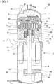
FIG. 1 is a cross-sectional view of a scroll compressor according to a first embodiment of the present invention. -
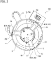
FIG. 2 is a sectional view in the axial direction of the scroll compressor according to the first embodiment of the present invention. -
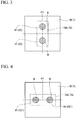
FIG. 3 is a schematic view showing a configuration of a welded portion according to a first embodiment of the present invention. -
FIG. 4 is a schematic diagram showing a configuration of a welded portion according to a second embodiment of the present invention. -
FIG. 5 is a schematic view showing a configuration of a welded portion according to a third embodiment of the present invention. -
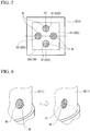
FIG. 6 is an explanatory view showing a cutting process included in a method for producing a scroll compressor according to an embodiment of the present invention. -
FIG. 7 is a view showing each process of a method for producing a scroll compressor according to the embodiment of the present invention. - A
scroll compressor 100 according to a first embodiment of the present invention will be described with reference to the drawings. As shown inFIG. 1 , thescroll compressor 100 includes ahousing 1 forming the outer shape of the device, a compression unit 2 (a scroll compressor body 2) provided in thehousing 1, and a drive unit 3 (an electric motor 3) for driving thecompression unit 2. Thecompression unit 2 and thedrive unit 3 are connected to each other by arotary shaft 4 extending along an axis O1. That is, rotational energy by thedrive unit 3 is transmitted immediately to thecompression unit 2 through therotary shaft 4. Thecompression unit 2 compresses a working fluid by this rotational energy and discharges it to the outside in a high pressure state. The working fluid in a high pressure state is used, for example, as a refrigerant in air conditioners and the like. Hereinafter, the configuration of each element will be described in detail. - The
housing 1 is provided with asuction pipe 11 for sucking a refrigerant gas as the working fluid from the outside, and adischarge pipe 12 for discharging the refrigerant gas that is in a high pressure state in adischarge chamber 67 after being compressed by thecompression unit 2. - The
rotary shaft 4 has a columnar shape centering on the axis O1. Therotary shaft 4 is supported so as to be rotatable within thehousing 1 by a main bearing 9A provided at an end portion (first end portion) on one side of therotary shaft 4 in anaxis 01 direction and by a sub bearing 9B provided at the other end portion (second end portion) on the other side of therotary shaft 4 which is the opposite side in the axis O1 direction when viewed from the main bearing 9A. A main bearingbody 75 is attached between the main bearing 9A and an outer peripheral surface of therotary shaft 4. Asub-bearing body 76 is attached between the sub bearing 9B and the outer peripheral surface of therotary shaft 4. - In the one end portion on one side of the
rotary shaft 4, aneccentric shaft 5 having a columnar shape and centering on an eccentric axis O2 that is different from the axis O1 is provided at an offset (eccentric) position with respect to the axis O1. The eccentric axis O2 is parallel to the axis O1. Theeccentric shaft 5 has a columnar shape protruding from the end portion of therotary shaft 4 toward the one side in the axis O1 direction. Accordingly, in a state in which therotary shaft 4 is rotating about the axis O1, theeccentric shaft 5 revolves around axis O1 of therotary shaft 4. - In addition, the main bearing 9A is provided with an Oldham
ring 91 for restricting a rotation (a rotation about the eccentric axis O2) of an orbitingscroll 7. Although the details are not shown, the Oldhamring 91 has projections that are fitted in a groove formed in anend plate 71 of theorbiting scroll 7. Furthermore, themain bearing 9A has athrust bearing 92 provided on an inner side in the radial direction when viewed from theOldham ring 91. Thethrust bearing 92 bears a load applied in the axis O1 direction by theorbiting scroll 7. - The
compression unit 2 includes a fixedscroll 6 and theorbiting scroll 7. Adischarge cover 8 is a member having a substantially disc shape and partitioning a space inside thehousing 1 in the axis O1 direction; and at the central portion of thedischarge cover 8, adischarge port 68 which communicates the refrigerant gas after compression to theabove discharge chamber 67, and adischarge valve 66 for preventing backflow of the refrigerant from high pressure side are provided. - The fixed
scroll 6 is a member having a substantially disc shape and fixed inside thehousing 1. Theorbiting scroll 7 faces the fixedscroll 6 from the axis O1 direction to form a compression chamber C therebetween. More particularly, the fixedscroll 6 includes anend plate 61 having a disc shape, and a fixedwrap 62 erected on a surface of the other side in the axial O1 direction of theend plate 61 from one side toward the other side in theaxis 01 direction. Theend plate 61 extends along a plane substantially perpendicular to the axis O1. The fixedwrap 62 is a wall body which is formed in a spiral shape when viewed from the axis O1 direction. More specifically, the fixedwrap 62 is formed of a plate-like member that is wound around a center of theend plate 61. As an example, the fixedwrap 62 may desirably be configured to form an involute curve centering on the axis O1 when viewed from the axis O1 direction. - On an outer side in the radial direction of the fixed
wrap 62, an outerperipheral wall 63 extending in a tubular shape along an outer periphery of theend plate 61 is formed. Furthermore, on an edge at the other side in the axis O1 direction of the outerperipheral wall 63, aflange 64 having an annular shape and extending outward in the radial direction is provided. The fixedscroll 6 is fixed to themain bearing 9A by bolts or the like via theflange 64. Furthermore, a fixedscroll discharge port 65 is formed in a central portion of the spiral of the fixedscroll 6. - The
orbiting scroll 7 includes theend plate 71 having a disc shape, and anorbiting wrap 72 having a spiral shape and provided on a surface at the one side in the axis O1 direction of theend plate 71. The orbitingwrap 72 may also desirably be configured to form an involute curve centering on the axis O2. - Furthermore, the orbiting
wrap 72 faces the fixedwrap 62 from the axis O1 direction and is disposed so as to overlap each other in a direction intersecting with the axis O1. In other words, the fixedwrap 62 and the orbitingwrap 72 are engaged with each other. In such engaging state, a predetermined space is formed between the fixedwrap 62 and the orbitingwrap 72. The volume of this space varies while the orbitingwrap 72 orbits. Thereby, it is possible to compress the refrigerant gas. - The
orbiting scroll 7 configured as described above is connected to one side in the axis O1 direction of therotary shaft 4 via abushing assembly 10 described later. Aboss 73 having a cylindrical shape is formed on a surface at the other side in theaxis 01 direction of theend plate 71 of the orbitingwrap 72. A central axis of theboss 73 is coaxial with the axis O2. Theeccentric shaft 5 formed on therotary shaft 4 is fitted into an internal space of theboss 73 from theaxis 01 direction through thebushing assembly 10. - In addition, lubricant oil is supplied to the rotary shaft 4 (the eccentric shaft 5) from the
oil supply pump 80. After lubricating a portion between thebush 101 of thebushing assembly 10 and the bearing 74 of theorbiting scroll 7, the lubricating oil is collected downwardly in thehousing 1. - Next, a detailed structure of the
sub bearing 9B will be described with reference toFIG. 2 . As shown in the figure, the sub bearing 9B includes aholder 78 having a tubular shape and supporting thesub-bearing body 76 from the outer peripheral side thereof, and a plurality (three) ofarms 79 that extends radially as centering on theholder 78. - The
holder 78 is provided at a position substantially coaxial with theaxis 01. Thearm 79 is a rod-like member that connects an innerperipheral surface 1A of thehousing 1 and the outer peripheral surface of theholder 78. The threearms 79 in the present embodiment have substantially the same shape and size with each other. - The end portion (an outer-
peripheral end portion 79A) at the outer side in the radial direction of thearm 79 is fixed to the innerperipheral surface 1A of thehousing 1 by a plug welding (plug weld). The outer-peripheral end portion 79A of thearm 79 has a substantially rectangular shape, when viewed from a direction in which thearm 79 extends (i.e., a radial of the axis O1). In addition, the outer-peripheral end portion 79A of thearm 79 is desirably forms in a curved shape corresponding to the shape of the innerperipheral surface 1A of thehousing 1. - Here, as shown in
FIGS. 2 and3 , a welding-use opening H1 penetrating thehousing 1 in the radial direction is formed at a portion corresponding to the outer-peripheral end portion 79A of thehousing 1. Furthermore, the welding-use opening H1 in this embodiment includes a plurality of holes H2. In a state in which the sub bearing 9B is arranged inside thehousing 1, the outer-peripheral end portion 79A is in a state of being exposed on the outer peripheral side of thehousing 1 through the holes H2. - Plug welding is performed to the outer-
peripheral end portion 79A of thearm 79 from the outer peripheral side of thehousing 1 via these holes H2. In this way, a space surrounded by an inner peripheral surface of the hole H2 and the outer-peripheral edge portion 79A is filled with weld metal, and then a welded portion W is formed. A portion of the welded portion W protruding to the outer circumferential side from the holes H2 (the welding-use opening HI) is cut after the welded portion W is hardened. That is, the welded portion W and an outerperipheral surface 1B of thehousing 1 are substantially flush with each other. - Here, the plurality of holes H2 are provided at intervals in at least one of the axis O1 direction and a peripheral direction of the axis O1. More specifically, in the present embodiment, two holes H2 are formed on the
housing 1 at intervals in the axis O1 direction (seeFIG. 3 ). Furthermore, these two holes H2 are formed symmetrically with respect to an imaginary line extending in the peripheral direction of the axis O1, when viewed from the direction in which thearm 79 extends. - Subsequently, main steps of the method for producing the
scroll compressor 100 will be described with reference toFIGS. 6 and7 . The method for producing thescroll compressor 100 according to the present embodiment includes an assembling process S1, a welding process S2, and a cutting process S3. - In the assembling process S1, the
electric motor 3, therotary shaft 4, the compression unit 2 (the scroll compressor body 2), themain bearing body 75, and thesub-bearing body 76 are housed in thehousing 1. - Then, in the welding process S2, plug welding of the
arm 79 of the sub bearing 9B is performed on the innerperipheral surface 1A of thehousing 1. As a result, the welded portion W described above is formed between the inner peripheral surface of the plurality of holes H2 and the outer-peripheral end portion 79A of thearm 79. At this time, due to the nature of plug welding, excess welding by welding is protruded outside the holes H2 (the outerperipheral surface 1B side of the housing 1) (seeFIG. 6 ). - The above protruding portions (the excess welding) are cut and removed in a subsequent cutting process S3. More specifically, in the cutting process S3, the excess welding of the welded portion W is removed by a cutting tool such as a grinder. As a result, the outer
peripheral surface 1B of thehousing 1 and the welded portion W are flush with each other. According to the above, every process in the method for producing thescroll compressor 100 according to the present embodiment is completed. - Next, the operation of the
scroll compressor 100 according to the present embodiment will be described. In starting the operation of thescroll compressor 100, first, therotary shaft 4 is rotationally driven about theaxis 01 by energizing the above drive unit 3 (the electric motor 3). - With the rotation of the
rotary shaft 4, theeccentric shaft 5 described above revolves around theaxis 01, and theorbiting scroll 7 attached to theeccentric shaft 5 orbits around the axis O1. Here, the rotation of theorbiting scroll 7 is restricted by theOldham ring 91 described above. Therefore, theorbiting scroll 7 performs a circular motion (orbits) along a locus drawn by the eccentric axis O2 as centering on theaxis 01 of therotary shaft 4. Along with this orbiting, the orbitingwrap 72 of theorbiting scroll 7 repeats a continuous relative movement relative to the fixedwrap 62 of the fixedscroll 6. Due to this relative movement, the volume of the compression chamber C formed between the fixedwrap 62 and the orbitingwrap 72 varies with time. - Although not shown in detail, first, during orbiting of the
orbiting scroll 7, the refrigerant gas as the working fluid is introduced into the compression chamber C from an opening created at an outer side in the radial direction of the orbiting wrap 72 (and the fixed wrap 62). In association with the orbiting of theorbiting scroll 7, the opening described above is closed. As a result, the refrigerant gas is confined within the compression chamber C. Subsequently, as theorbiting scroll 7 still orbits, the refrigerant gas moves radially inward (i.e., the eccentric axis O2 side). At this time, since the orbitingwrap 72 and the fixedwrap 62 are formed in the spiral shape as described above, the volume of the compression chamber C formed by the both is contracted gradually toward the inner side in the radial direction. As a result, the refrigerant gas is compressed. Eventually, in the vicinity of the center portion of the orbiting scroll 7 (or the fixed scroll 6), the refrigerant gas reaches the maximum pressure, and then is supplied to the outside through the above fixedscroll discharge port 65 and thedischarge pipe 12 of thehousing 1. - Here, as described above, in the arm 79 (the welded portion W) in the sub bearing 9B, a load acting inward or outward in the radial direction is applied sinusoidally by reaction force when compressing the refrigerant gas and a moment of the members such as the balance weight for adjusting the balance during rotation.
- For example, when the
arm 79 is fixed to thehousing 1 with a single welded portion W, fatigue failure or the like may occur due to localized concentration of the above stress. However, in thescroll compressor 100 according to the present embodiment, two welded portions W are formed by plug welding via the plurality (two) of holes H2 as described above. Accordingly, it is possible to firmly and stably fix the arm 79 (thesub bearing 9B) to the innerperipheral surface 1A of thehousing 1. - Furthermore, according to the above-described structure, since a plurality of holes H2 are provided at symmetrical positions with respect to the
arm 79, it is possible to reduce the possibility that only a specific welded portion W is subjected to stress. Thus, it is possible to stably fix the sub bearing 9B on the innerperipheral surface 1A thehousing 1. - In addition, according to the above-described structure, the excess welding created outside the holes H2 by plug welding is removed by cutting (the cutting process S3). Therefore, the welded portion W and the outer-
peripheral end portion 79A of thearm 79 never protrude outward in the radial direction from the outerperipheral surface 1B of thehousing 1, and it is possible to reduce the possibility of cracks, or the like, occurring in the welded portion due to stress concentration in the protruding region. - The first embodiment of the present invention has been described with reference to the drawings. However, the above embodiment is merely an example, and thus, various modifications and the like can be applied to this.
- For example, the above embodiment has been described as an example in which two holes H2 are provided along the axis O1 direction. However, the number of holes H2 is not limited to two, optionally, four, six, or more even number of holes may be provided, if necessary.
- Next, a second embodiment of the present invention will be described with reference to
FIG. 4 . - In the present embodiment, aspects of the holes H2 and the welded portion W are different from the first embodiment. More specifically, in this embodiment, two holes H21 are formed at intervals in the peripheral direction of the
axis 01. That is, these two holes H21 are formed at symmetrical positions with respect to the axis O1. Furthermore, the outer-peripheral end portion 79A of thearm 79 also has a rectangular shape extending in the peripheral direction of the axis O1 so as to correspond to the arrangement direction of the two holes H21. - For each of the holes H21 described above, plug welding similar to the first embodiment is performed. Further, the excess welding of the welded portion W is removed by the same process as the above cutting process S3. Thus, the welded portion W and the outer
peripheral surface 1B of thehousing 1 are flush with each other. - According to such a configuration, in addition to stress generated with the orbiting of the
orbiting scroll 7, thearm 79 can resist against stress acted in the axis O1 direction. That is, it is possible to further enhance the stability of thescroll compressor 100. - Next, a third embodiment of the present invention will be described with reference to
FIG. 5 . As shown in the figure, in the present embodiment, a plurality (four) holes H22 are arranged at intervals along the axis O1 direction and along the peripheral direction of the axis O1. Furthermore, the outer-peripheral end portion 79A of thearm 79 also has a substantially square shape so as to correspond to a region where these holes H22 are provided. - For each of the holes H22 described above, plug welding similar to the first embodiment is performed. Further, the excess welding of the welded portion W is removed after the same process as the above cutting process S3. Thus, the welded portion W and the outer
peripheral surface 1B of thehousing 1 are flush with each other. - According to such configuration, in addition to stress generated with the orbiting of the
orbiting scroll 7, thearm 79 can resist with more sufficient margin against stress acted in theaxis 01 direction. That is, it is possible to further enhance the stability of thescroll compressor 100. - According to the scroll compressor of the present invention, it is possible to realize stable operation for a long term.
-
- 1
- Housing
- 2
- Compression unit
- 3
- Drive unit (electric motor)
- 4
- Rotary shaft
- 5
- Eccentric shaft
- 6
- Fixed scroll
- 7
- Orbiting scroll
- 8
- Discharge cover
- 9A
- Main bearing
- 9B
- Sub bearing
- 10
- Bush assembly
- 11
- Suction piping
- 12
- Discharge piping
- 61
- End plate
- 62
- Fixed wrap
- 63
- Outer peripheral wall
- 64
- Flange
- 65
- Fixed scroll discharge port
- 66
- Discharge valve
- 67
- Discharge chamber
- 68
- Discharge port
- 71
- End plate
- 72
- Orbiting wrap
- 73
- Boss
- 74
- Bearing
- 75
- Main bearing body
- 76
- Sub-bearing body
- 79
- Arm
- 80
- Lubrication pump
- 91
- Oldham ring
- 92
- Thrust bearing
- 100
- Scroll compressor
- 101
- Bush
- C
- Compression chamber
- H1
- Welding-use opening
- H2, H21, H22
- Hole
- O1
- Axis
- O2
- Eccentric axis
- W
- Welded portion
Claims (5)
- A scroll compressor comprising:an electric motor;a rotary shaft rotationally driven about an axis thereof by the electric motor,a scroll compressor body driven by rotation of the rotary shaft;a main bearing rotatably supporting the rotary shaft between the electric motor and the scroll compressor body;a sub bearing rotatably supporting the rotary shaft on an opposite side of the main bearing of the electric motor, and provided with a plurality of arms at intervals in a peripheral direction of the rotary shaft, the plurality of arms extending along a radial direction of the rotary shaft; anda housing having a tubular shape extending along the axis, housing the electric motor, the rotary shaft, the scroll compressor body, the main bearing, and the sub bearing, and having a welding-use opening penetrating in the radial direction at positions corresponding to an outer-peripheral end portion of each arm,wherein the welding-use opening corresponding to each arm includes a plurality of holes that are formed at intervals in at least one of the peripheral direction and an axial direction of the rotary shaft, andwherein welded portions are formed by filling the holes and welding an inner peripheral surface of each hole and the outer-peripheral end portion of the corresponding arm.
- The scroll compressor according to Claim 1, wherein
the holes are provided at symmetrical positions with respect to at least one of the peripheral direction and the axial direction when viewed from the direction in which the arm extends. - The scroll compressor according to Claim 1 or 2, wherein
the welded portion and an outer peripheral surface of the housing are flush with each other. - A method for producing the scroll compressor that comprises:an electric motor;a rotary shaft rotationally driven about an axis thereof by the electric motor,a scroll compressor body driven by rotation of the rotary shaft;a main bearing rotatably supporting the rotary shaft between the electric motor and the scroll compressor body;a sub bearing rotatably supporting the rotary shaft on an opposite side of the main bearing of the electric motor, and provided with a plurality of arms at intervals in a peripheral direction of the rotary shaft, the plurality of arms extending along a radial direction of the rotary shaft; anda housing having a tubular shape extending along the axis, housing the electric motor, the rotary shaft, the scroll compressor body, the main bearing, and the sub bearing, and having a welding-use opening penetrating in the radial direction at positions corresponding to an outer-peripheral end portion of each arm,the method comprising:an assembling process that houses the electric motor, the rotary shaft, the scroll compressor body, the main bearing, and the sub bearing within the housing;a welding process that exposes the outer-peripheral end portion of each arm from the welding-use opening and provides a welded portion to the welding-use opening by welding; anda cutting process that cuts a portion protruding from the welding-use opening to the outer peripheral side of the housing.
- The method for producing the scroll compressor according to Claim 4, wherein
in the cutting process, the welded portion is cut so that the welded portion and the outer peripheral surface the housing are flush with each other.
Applications Claiming Priority (2)
| Application Number | Priority Date | Filing Date | Title |
|---|---|---|---|
| JP2015217462A JP2017089426A (en) | 2015-11-05 | 2015-11-05 | Scroll compressor, and method of manufacturing scroll compressor |
| PCT/JP2016/080218 WO2017077827A1 (en) | 2015-11-05 | 2016-10-12 | Scroll compressor and method for producing scroll compressor |
Publications (2)
| Publication Number | Publication Date |
|---|---|
| EP3339644A1 true EP3339644A1 (en) | 2018-06-27 |
| EP3339644A4 EP3339644A4 (en) | 2019-04-17 |
Family
ID=58661943
Family Applications (1)
| Application Number | Title | Priority Date | Filing Date |
|---|---|---|---|
| EP16861894.0A Withdrawn EP3339644A4 (en) | 2015-11-05 | 2016-10-12 | SPIRAL COMPRESSOR AND METHOD FOR PRODUCING SPIRAL COMPRESSOR |
Country Status (4)
| Country | Link |
|---|---|
| EP (1) | EP3339644A4 (en) |
| JP (1) | JP2017089426A (en) |
| CN (1) | CN107850070A (en) |
| WO (1) | WO2017077827A1 (en) |
Cited By (2)
| Publication number | Priority date | Publication date | Assignee | Title |
|---|---|---|---|---|
| DE102021206432A1 (en) | 2021-06-22 | 2022-12-22 | Brose Fahrzeugteile SE & Co. Kommanditgesellschaft, Würzburg | scroll machine |
| US12049895B2 (en) | 2021-08-05 | 2024-07-30 | Daikin Industries, Ltd. | Scroll compressor and refrigeration cycle apparatus |
Families Citing this family (2)
| Publication number | Priority date | Publication date | Assignee | Title |
|---|---|---|---|---|
| JP6791302B2 (en) * | 2019-05-21 | 2020-11-25 | ダイキン工業株式会社 | Compressor |
| CN111922636B (en) * | 2020-07-17 | 2022-01-04 | 无锡双鸟科技股份有限公司 | Manufacturing method of electric scroll compressor of new energy automobile |
Family Cites Families (12)
| Publication number | Priority date | Publication date | Assignee | Title |
|---|---|---|---|---|
| JPS59108882A (en) * | 1982-12-13 | 1984-06-23 | Sanyo Electric Co Ltd | Closed-type rotary compressor |
| JPS61178578A (en) * | 1985-02-05 | 1986-08-11 | Matsushita Refrig Co | Sealed type compressor |
| CN1075170C (en) * | 1994-02-01 | 2001-11-21 | 三菱重工业株式会社 | Vortex hydraulic mechanism |
| JPH07217554A (en) * | 1994-02-01 | 1995-08-15 | Mitsubishi Heavy Ind Ltd | Scroll type fluid machinery |
| JPH11182433A (en) * | 1997-12-16 | 1999-07-06 | Sanyo Electric Co Ltd | Enclosed compressor |
| JP2005195005A (en) * | 2003-12-12 | 2005-07-21 | Fujitsu General Ltd | Assembling method of scroll compressor |
| JP2008190467A (en) * | 2007-02-06 | 2008-08-21 | Mitsubishi Heavy Ind Ltd | Hermetic electric compressor |
| JP5012110B2 (en) * | 2007-03-15 | 2012-08-29 | 三菱電機株式会社 | Sealed container and method for manufacturing sealed container |
| JP2010236449A (en) * | 2009-03-31 | 2010-10-21 | Daikin Ind Ltd | Rotating fluid machine, fixing member of rotating fluid machine, and processing method of fixing member of rotating fluid machine |
| JP5195962B2 (en) * | 2011-05-11 | 2013-05-15 | 三菱電機株式会社 | Rotary compressor |
| CN104373353B (en) * | 2013-08-15 | 2018-01-19 | 珠海格力节能环保制冷技术研究中心有限公司 | Screw compressor and its bearing close heart method |
| CN104632628B (en) * | 2015-02-05 | 2017-01-18 | 浙江博阳压缩机有限公司 | DC-powered air condition compressor of electrical vehicle |
-
2015
- 2015-11-05 JP JP2015217462A patent/JP2017089426A/en active Pending
-
2016
- 2016-10-12 WO PCT/JP2016/080218 patent/WO2017077827A1/en not_active Ceased
- 2016-10-12 EP EP16861894.0A patent/EP3339644A4/en not_active Withdrawn
- 2016-10-12 CN CN201680043830.XA patent/CN107850070A/en active Pending
Cited By (3)
| Publication number | Priority date | Publication date | Assignee | Title |
|---|---|---|---|---|
| DE102021206432A1 (en) | 2021-06-22 | 2022-12-22 | Brose Fahrzeugteile SE & Co. Kommanditgesellschaft, Würzburg | scroll machine |
| US12049895B2 (en) | 2021-08-05 | 2024-07-30 | Daikin Industries, Ltd. | Scroll compressor and refrigeration cycle apparatus |
| EP4382750A4 (en) * | 2021-08-05 | 2024-08-28 | Daikin Industries, Ltd. | SCROLL COMPRESSOR AND REFRIGERATION CYCLE DEVICE |
Also Published As
| Publication number | Publication date |
|---|---|
| WO2017077827A1 (en) | 2017-05-11 |
| CN107850070A (en) | 2018-03-27 |
| JP2017089426A (en) | 2017-05-25 |
| EP3339644A4 (en) | 2019-04-17 |
Similar Documents
| Publication | Publication Date | Title |
|---|---|---|
| KR101480970B1 (en) | Compressor with retaining mechanism | |
| KR102027695B1 (en) | Scroll compressor | |
| US9181949B2 (en) | Compressor with oil return passage formed between motor and shell | |
| EP2659144B1 (en) | Hermetic compressor and manufacturing method thereof | |
| JP2001221171A (en) | Scroll machine | |
| JP6685690B2 (en) | Scroll fluid machinery | |
| US20130251551A1 (en) | Compressor shell with multiple diameters | |
| CN107850070A (en) | The manufacture method of screw compressor, screw compressor | |
| EP3315777B1 (en) | Scroll compressor and method for producing scroll compressor | |
| EP3308027B1 (en) | Ring weld blocker in discharge check valve | |
| JP2018044492A (en) | Scroll compressor | |
| JP6685689B2 (en) | Scroll fluid machinery | |
| JP4045567B2 (en) | Compressor and its assembly method | |
| KR101708307B1 (en) | Hermetic compressor and manufacturing method thereof | |
| JP4415178B2 (en) | Scroll fluid machine and assembly method thereof | |
| JP5430208B2 (en) | Sealed fluid machinery | |
| CN106662105B (en) | scroll compressor | |
| EP4711615A1 (en) | Scroll compressor | |
| EP4460635B1 (en) | Compressor | |
| EP3396166A1 (en) | Rotary machine | |
| KR20250044559A (en) | Scroll compressor | |
| JP4748585B2 (en) | Manufacturing method of scroll compressor | |
| JP6627557B2 (en) | Bearing housing and rotating machine | |
| KR101708308B1 (en) | Hermetic compressor and manufacturing method thereof | |
| KR20190004985A (en) | Compressor having structure of gradually changing oil path area |
Legal Events
| Date | Code | Title | Description |
|---|---|---|---|
| STAA | Information on the status of an ep patent application or granted ep patent |
Free format text: STATUS: THE INTERNATIONAL PUBLICATION HAS BEEN MADE |
|
| PUAI | Public reference made under article 153(3) epc to a published international application that has entered the european phase |
Free format text: ORIGINAL CODE: 0009012 |
|
| STAA | Information on the status of an ep patent application or granted ep patent |
Free format text: STATUS: REQUEST FOR EXAMINATION WAS MADE |
|
| 17P | Request for examination filed |
Effective date: 20180125 |
|
| AK | Designated contracting states |
Kind code of ref document: A1 Designated state(s): AL AT BE BG CH CY CZ DE DK EE ES FI FR GB GR HR HU IE IS IT LI LT LU LV MC MK MT NL NO PL PT RO RS SE SI SK SM TR |
|
| AX | Request for extension of the european patent |
Extension state: BA ME |
|
| DAV | Request for validation of the european patent (deleted) | ||
| DAX | Request for extension of the european patent (deleted) | ||
| A4 | Supplementary search report drawn up and despatched |
Effective date: 20190314 |
|
| RIC1 | Information provided on ipc code assigned before grant |
Ipc: F04C 23/00 20060101ALI20190308BHEP Ipc: F04C 18/02 20060101AFI20190308BHEP Ipc: F04C 29/00 20060101ALI20190308BHEP |
|
| STAA | Information on the status of an ep patent application or granted ep patent |
Free format text: STATUS: EXAMINATION IS IN PROGRESS |
|
| 17Q | First examination report despatched |
Effective date: 20191129 |
|
| STAA | Information on the status of an ep patent application or granted ep patent |
Free format text: STATUS: THE APPLICATION IS DEEMED TO BE WITHDRAWN |
|
| 18D | Application deemed to be withdrawn |
Effective date: 20201014 |