EP3339595A1 - Method for selective catalytic reduction system - Google Patents
Method for selective catalytic reduction system Download PDFInfo
- Publication number
- EP3339595A1 EP3339595A1 EP16205950.5A EP16205950A EP3339595A1 EP 3339595 A1 EP3339595 A1 EP 3339595A1 EP 16205950 A EP16205950 A EP 16205950A EP 3339595 A1 EP3339595 A1 EP 3339595A1
- Authority
- EP
- European Patent Office
- Prior art keywords
- hydrolysis catalyst
- matter
- def
- states
- catalytic reduction
- Prior art date
- Legal status (The legal status is an assumption and is not a legal conclusion. Google has not performed a legal analysis and makes no representation as to the accuracy of the status listed.)
- Granted
Links
Images

Classifications
-
- F—MECHANICAL ENGINEERING; LIGHTING; HEATING; WEAPONS; BLASTING
- F01—MACHINES OR ENGINES IN GENERAL; ENGINE PLANTS IN GENERAL; STEAM ENGINES
- F01N—GAS-FLOW SILENCERS OR EXHAUST APPARATUS FOR MACHINES OR ENGINES IN GENERAL; GAS-FLOW SILENCERS OR EXHAUST APPARATUS FOR INTERNAL-COMBUSTION ENGINES
- F01N3/00—Exhaust or silencing apparatus having means for purifying, rendering innocuous, or otherwise treating exhaust
- F01N3/08—Exhaust or silencing apparatus having means for purifying, rendering innocuous, or otherwise treating exhaust for rendering innocuous
- F01N3/10—Exhaust or silencing apparatus having means for purifying, rendering innocuous, or otherwise treating exhaust for rendering innocuous by thermal or catalytic conversion of noxious components of exhaust
- F01N3/18—Exhaust or silencing apparatus having means for purifying, rendering innocuous, or otherwise treating exhaust for rendering innocuous by thermal or catalytic conversion of noxious components of exhaust characterised by methods of operation; Control
- F01N3/20—Exhaust or silencing apparatus having means for purifying, rendering innocuous, or otherwise treating exhaust for rendering innocuous by thermal or catalytic conversion of noxious components of exhaust characterised by methods of operation; Control specially adapted for catalytic conversion
- F01N3/206—Adding periodically or continuously substances to exhaust gases for promoting purification, e.g. catalytic material in liquid form, NOx reducing agents
- F01N3/208—Control of selective catalytic reduction [SCR], e.g. by adjusting the dosing of reducing agent
-
- F—MECHANICAL ENGINEERING; LIGHTING; HEATING; WEAPONS; BLASTING
- F01—MACHINES OR ENGINES IN GENERAL; ENGINE PLANTS IN GENERAL; STEAM ENGINES
- F01N—GAS-FLOW SILENCERS OR EXHAUST APPARATUS FOR MACHINES OR ENGINES IN GENERAL; GAS-FLOW SILENCERS OR EXHAUST APPARATUS FOR INTERNAL-COMBUSTION ENGINES
- F01N3/00—Exhaust or silencing apparatus having means for purifying, rendering innocuous, or otherwise treating exhaust
- F01N3/08—Exhaust or silencing apparatus having means for purifying, rendering innocuous, or otherwise treating exhaust for rendering innocuous
- F01N3/10—Exhaust or silencing apparatus having means for purifying, rendering innocuous, or otherwise treating exhaust for rendering innocuous by thermal or catalytic conversion of noxious components of exhaust
- F01N3/18—Exhaust or silencing apparatus having means for purifying, rendering innocuous, or otherwise treating exhaust for rendering innocuous by thermal or catalytic conversion of noxious components of exhaust characterised by methods of operation; Control
- F01N3/20—Exhaust or silencing apparatus having means for purifying, rendering innocuous, or otherwise treating exhaust for rendering innocuous by thermal or catalytic conversion of noxious components of exhaust characterised by methods of operation; Control specially adapted for catalytic conversion
- F01N3/206—Adding periodically or continuously substances to exhaust gases for promoting purification, e.g. catalytic material in liquid form, NOx reducing agents
- F01N3/2066—Selective catalytic reduction [SCR]
-
- F—MECHANICAL ENGINEERING; LIGHTING; HEATING; WEAPONS; BLASTING
- F01—MACHINES OR ENGINES IN GENERAL; ENGINE PLANTS IN GENERAL; STEAM ENGINES
- F01N—GAS-FLOW SILENCERS OR EXHAUST APPARATUS FOR MACHINES OR ENGINES IN GENERAL; GAS-FLOW SILENCERS OR EXHAUST APPARATUS FOR INTERNAL-COMBUSTION ENGINES
- F01N9/00—Electrical control of exhaust gas treating apparatus
- F01N9/005—Electrical control of exhaust gas treating apparatus using models instead of sensors to determine operating characteristics of exhaust systems, e.g. calculating catalyst temperature instead of measuring it directly
-
- F—MECHANICAL ENGINEERING; LIGHTING; HEATING; WEAPONS; BLASTING
- F01—MACHINES OR ENGINES IN GENERAL; ENGINE PLANTS IN GENERAL; STEAM ENGINES
- F01N—GAS-FLOW SILENCERS OR EXHAUST APPARATUS FOR MACHINES OR ENGINES IN GENERAL; GAS-FLOW SILENCERS OR EXHAUST APPARATUS FOR INTERNAL-COMBUSTION ENGINES
- F01N2240/00—Combination or association of two or more different exhaust treating devices, or of at least one such device with an auxiliary device, not covered by indexing codes F01N2230/00 or F01N2250/00, one of the devices being
- F01N2240/40—Combination or association of two or more different exhaust treating devices, or of at least one such device with an auxiliary device, not covered by indexing codes F01N2230/00 or F01N2250/00, one of the devices being a hydrolysis catalyst
-
- F—MECHANICAL ENGINEERING; LIGHTING; HEATING; WEAPONS; BLASTING
- F01—MACHINES OR ENGINES IN GENERAL; ENGINE PLANTS IN GENERAL; STEAM ENGINES
- F01N—GAS-FLOW SILENCERS OR EXHAUST APPARATUS FOR MACHINES OR ENGINES IN GENERAL; GAS-FLOW SILENCERS OR EXHAUST APPARATUS FOR INTERNAL-COMBUSTION ENGINES
- F01N2610/00—Adding substances to exhaust gases
-
- F—MECHANICAL ENGINEERING; LIGHTING; HEATING; WEAPONS; BLASTING
- F01—MACHINES OR ENGINES IN GENERAL; ENGINE PLANTS IN GENERAL; STEAM ENGINES
- F01N—GAS-FLOW SILENCERS OR EXHAUST APPARATUS FOR MACHINES OR ENGINES IN GENERAL; GAS-FLOW SILENCERS OR EXHAUST APPARATUS FOR INTERNAL-COMBUSTION ENGINES
- F01N2610/00—Adding substances to exhaust gases
- F01N2610/02—Adding substances to exhaust gases the substance being ammonia or urea
-
- F—MECHANICAL ENGINEERING; LIGHTING; HEATING; WEAPONS; BLASTING
- F01—MACHINES OR ENGINES IN GENERAL; ENGINE PLANTS IN GENERAL; STEAM ENGINES
- F01N—GAS-FLOW SILENCERS OR EXHAUST APPARATUS FOR MACHINES OR ENGINES IN GENERAL; GAS-FLOW SILENCERS OR EXHAUST APPARATUS FOR INTERNAL-COMBUSTION ENGINES
- F01N2900/00—Details of electrical control or of the monitoring of the exhaust gas treating apparatus
- F01N2900/04—Methods of control or diagnosing
- F01N2900/0406—Methods of control or diagnosing using a model with a division of the catalyst or filter in several cells
-
- Y—GENERAL TAGGING OF NEW TECHNOLOGICAL DEVELOPMENTS; GENERAL TAGGING OF CROSS-SECTIONAL TECHNOLOGIES SPANNING OVER SEVERAL SECTIONS OF THE IPC; TECHNICAL SUBJECTS COVERED BY FORMER USPC CROSS-REFERENCE ART COLLECTIONS [XRACs] AND DIGESTS
- Y02—TECHNOLOGIES OR APPLICATIONS FOR MITIGATION OR ADAPTATION AGAINST CLIMATE CHANGE
- Y02T—CLIMATE CHANGE MITIGATION TECHNOLOGIES RELATED TO TRANSPORTATION
- Y02T10/00—Road transport of goods or passengers
- Y02T10/10—Internal combustion engine [ICE] based vehicles
- Y02T10/12—Improving ICE efficiencies
-
- Y—GENERAL TAGGING OF NEW TECHNOLOGICAL DEVELOPMENTS; GENERAL TAGGING OF CROSS-SECTIONAL TECHNOLOGIES SPANNING OVER SEVERAL SECTIONS OF THE IPC; TECHNICAL SUBJECTS COVERED BY FORMER USPC CROSS-REFERENCE ART COLLECTIONS [XRACs] AND DIGESTS
- Y02—TECHNOLOGIES OR APPLICATIONS FOR MITIGATION OR ADAPTATION AGAINST CLIMATE CHANGE
- Y02T—CLIMATE CHANGE MITIGATION TECHNOLOGIES RELATED TO TRANSPORTATION
- Y02T10/00—Road transport of goods or passengers
- Y02T10/10—Internal combustion engine [ICE] based vehicles
- Y02T10/40—Engine management systems
Definitions
- the present invention relates to selective catalytic reduction (SCR) systems for treating exhaust gasses.
- SCR selective catalytic reduction
- he present invention relates to methods for improving the efficiency and functionality of SCR systems.
- SCR Selective catalytic reduction
- Diesel exhaust fluid DEF
- urea which undergoes a thermolysis and hydrolysis within the exhaust passage whereby ammonia is produced.
- the ammonia passes into a SCR catalyst where it reacts with the exhaust gas, wherein nitrogen oxides (NOx) present in the exhaust gas are converted to nitrogen and water before passing out of the exhaust into the atmosphere.
- NOx nitrogen oxides
- US2008307967A1 discloses an arrangement in which DEF is hydrolysed in a supply passage which is outside of a main exhaust passage. Specifically, DEF is dosed onto a hydrolysis catalyst and hydrolysed to ammonia. The ammonia flows downstream to an inlet of a SCR catalyst where it acts to reduce NOx.
- a known control process followed by a SCR system such as the one disclosed in US'967 involves dosing the hydrolysis reactor with DEF when ammonia is required to reduce NOx.
- a hydrolysis catalyst being dosed with Diesel Exhaust Fluid (DEF)
- DEF Diesel Exhaust Fluid
- the numerical model comprises a multi-phase model that models characteristics of a plurality of states of matter for each of a plurality of substances.
- the step of evaluating comprises determining values for a plurality of state parameters associated with each of the plurality of states of matter for each of the plurality of substances.
- the matter state parameters may be representative of at least one of: phase transitions; chemical reaction parameters for at least one of the states of matter; energy balance between a plurality of states of matter; or mass balance between a plurality of states of matter.
- the numerical model comprises a spatial model of a hydrolysis catalyst to be modelled, the hydrolysis catalyst being divided into a plurality of discrete spatial units, and wherein the step of evaluating comprises evaluating the characteristics of each of the plurality of states of matter for each of the plurality of substances in each of the discrete spatial units.
- a selective catalytic reduction system for treating exhaust gas in an exhaust passage, the system comprising:
- the plurality of sensors comprises at least one of: a Nitrogen Oxide sensor; an inlet temperature sensor, an outlet temperature sensor; or an NOx sensor.
- a computer program product containing one or more sequences of machine-readable instructions for performing the method as set out above.
- an exhaust apparatus for an engine comprising the selective catalytic reduction system as set out above.
- an engine comprising the selective catalytic reduction system as set out above.
- FIG. 1 shows an exemplary selective catalytic reduction (SCR) system 10.
- SCR selective catalytic reduction
- the system is located in an exhaust passage 12 that conveys exhaust gas away from an engine (not shown).
- the exhaust gas passes through a diesel oxidation catalyst (DOC, not shown) of a known type, which catalyses an oxidation reaction of hydrocarbons, nitric oxide and carbon monoxide in the exhaust gas to produce carbon dioxide, nitrogen dioxide and water.
- DOC diesel oxidation catalyst
- DEF diesel exhaust fluid
- SCR catalyst 20 Located downstream of the hydrolysis catalyst is a SCR catalyst 20 of a known type. It will be appreciated that the system 10 may comprise additional components, such as an ammonia slip catalyst or a diesel particulate filter.
- the system includes a controller 26 that is in communication with the DEF dosing unit, and is configured to control a rate at which the DEF dosing unit injects DEF onto the hydrolysis catalyst.
- the system additionally includes a plurality of sensors in communication with the controller. Specifically, upstream of the hydrolysis catalyst is located a Nitrogen Oxide (NOx) sensor 28 and an inlet temperature sensor 30. Located between the hydrolysis catalyst and the SCR catalyst is an outlet temperature sensor 32 and a NO x sensor 34 located downstream of the SCR catalyst.
- NOx Nitrogen Oxide
- NOx Nitrogen Oxide
- Each of the various sensor may be connected to one or more inputs and/or outputs provided on the controller.
- the controller regulates the DEF dosage rate based, in part, on the measurement data received from the various sensors of the system.
- the controller may comprise a plurality of individual sub-controllers 26a, 26b.
- Each of the sub-controllers may perform specific operations, e.g. the first sub-controller 26a may perform operations relating to the performance of the SCR catalyst 20 and the second sub-controller 26b may perform operations relating to the performance of the hydrolysis catalyst 18.
- the numerical model may be implemented to take into account a number of parameters and/or a number of mechanisms.
- a number of exemplary parameters and mechanisms will be discussed in the following. It will be appreciated that these are purely for exemplary purposes and are not intended to be in any way limiting. It will also be appreciated that examples wherein additional or alternative parameters and mechanisms are taken into account may be envisaged by the skilled person, and that such examples fall within the scope of the present claims.
- the numerical model may take into account matter state transitions, as well as related effect, between a plurality of states of matter.
- Chemical reactions in a catalytic system may involve a plurality of states of matter.
- DEF that is injected into the exhaust system (as described with reference to Figure 1 above) is typically injected in liquid form onto the hydrolysis catalyst. On the surface of the hydrolysis catalyst, the DEF may either evaporate (i.e. transition into a gaseous state), form deposits (i.e. transition into a solid state) or accumulate in the form of a film.
- Matter state transitions may have a direct effect on the operating conditions of the exhaust system. For example, when transitioning from a liquid to a gaseous state, a significant amount of energy will be consumed and a substance may increase its volume, which in turn may affect e.g the pressure or the temperature in the exhaust system.
- the numerical model comprises modelling mass balance of species in the catalytic system for at least some of the states of matter.
- the mass balance of a plurality of species is modelled for three states of matter (i.e. solid, liquid and gas).
- the numerical model may comprise modelling energy balances of a plurality of substances in the catalytic system for at least some of the states of matter, and comprise a film momentum equation.
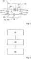
- Figure 2 illustrates schematically an exemplary numerical model 200 of a surface of a hydrolysis catalyst.
- the numerical model comprises a multi-phase model that models characteristics of a plurality of matters states for each of a plurality of species.
- the characteristics of three states of matter are modelled: gaseous 204, liquid 206 (e.g. DEF) and solid 208 (substrate wall, washcoat or deposit) states.
- the hydrolysis catalyst is, in the present example, divided into a number of discrete modelling units 210, each of which model a finite section of the hydrolysis catalyst. This allows for variation in the conditions along the length of the hydrolysis catalyst to be modelled and taken into account, thereby increasing the accuracy of the modelling results. It will be appreciated that, while the following is described with reference to a hydrolysis catalyst, it could in principle be applied to any suitable component of the aftertreatment system.
- Additional energy balances in gas and solid phases may, in some examples, be advantageous or necessary.
- one or more specific terms in the above equation may become dominant, and one or more specific terms may become negligible. Under such circumstances, such negligible terms may be neglected or ignored in order to reduce the complexity of the calculation, and by extension increase the speed of the model.
- specific parameters can be assumed to be at a pseudo steady-state to simplify the calculations and increase the speed of the model.
- the term on the left hand side of the equation is the time dependent accumulation of energy in a discrete modelling unit of the film.
- q conv 212 and q cond 214 describe transfer of energy by convective flow and conduction between a particular discrete modelling unit within the film and one or more adjacent discrete modelling units within the film.
- the fifth term on the right hand side of the equation describes heat flux between the solid and the film. Once the film's boiling point is reached, the heat flux changes from conduction (q hfcond 216a) to boiling (q hfboil 216b), and depends on the excess temperature.
- q rxn 218 describes heat absorbed or released by reactions that may occur within the film. Typically, a majority of energy is adsorbed or released during solid phases (e.g. thermolysis and formation of urea deposit species in the deposit layer or hydrolysis or adsorption in the washcoat).
- q vap 220 describes energy transfer as a result of vaporization of a compound in the liquid state into a gaseous state (i.e. water from the film).
- q drop 222 describes transferred to the film by incoming DEF droplets impacting the film.
- q extconv 224 describes energy transfer due to external convective heat transfer between the gas and liquid phase.
- Figure 2 shows only a single discrete modelling unit. It will be appreciated, however, that in reality a plurality of discrete modelling units may be used to model at least a part of a surface in the system.
- a numerical model of a hydrolysis catalyst is provided.
- the numerical model is identical to the exemplary model described with reference to Figure 2 .
- the numerical model comprises a spatial model of a hydrolysis catalyst to be modelled, the hydrolysis catalyst being divided into a plurality of discrete spatial units, and comprises evaluating characteristics of each of the plurality of states of matter for each of the plurality of substances in each of the discrete spatial units.
- the numerical model may comprise alternative or additional characteristics and parameters.
- the numerical model is evaluated to derive a predicted concentration of ammonia generated by the hydrolysis catalyst.
- the numerical model may be evaluated in any suitable fashion.
- the step of evaluating comprises determining values for a plurality of matter state parameters associated with each of the plurality of states of matter for each of the plurality of substances.
- the matter state parameters may be representative of any of a plurality of suitable or relevant physical characteristics or effects.
- the matter state parameters are representative of at least one of: state transitions between states of matter; chemical reaction parameters for at least one of the states of matter; energy balance between a plurality of states of matter; or mass balance between a plurality of states of matter.
- the numerical model is embedded into and evaluated by a suitable processing unit forming part of the SCR system. In other examples, the numerical model may be evaluated by a processing unit that is located remotely from the SCR system.
- the numerical model may be evaluated in any suitable manner.
- the numerical model is implemented and evaluated by a processing unit forming part of an SCR system (such as the one shown in Figure 1 ).
- a third step 303 the predicted concentration of ammonia is used to control dosage of DEF onto the hydrolysis catalyst.
- This step may be implemented in any suitable fashion.
Landscapes
- Engineering & Computer Science (AREA)
- Chemical & Material Sciences (AREA)
- Chemical Kinetics & Catalysis (AREA)
- Combustion & Propulsion (AREA)
- Mechanical Engineering (AREA)
- General Engineering & Computer Science (AREA)
- Health & Medical Sciences (AREA)
- Toxicology (AREA)
- Analytical Chemistry (AREA)
- Exhaust Gas After Treatment (AREA)
- Exhaust Gas Treatment By Means Of Catalyst (AREA)
Abstract
Description
- The present invention relates to selective catalytic reduction (SCR) systems for treating exhaust gasses. In particular, he present invention relates to methods for improving the efficiency and functionality of SCR systems.
- Selective catalytic reduction (SCR) systems are known and are generally included in the exhaust systems of diesel engines in order to treat the exhaust gases of such engines. Such systems involve the introduction of a diesel exhaust fluid (DEF) into exhaust gas flowing in an exhaust passage of an engine. The DEF contains urea which undergoes a thermolysis and hydrolysis within the exhaust passage whereby ammonia is produced. The ammonia passes into a SCR catalyst where it reacts with the exhaust gas, wherein nitrogen oxides (NOx) present in the exhaust gas are converted to nitrogen and water before passing out of the exhaust into the atmosphere.
- A number of SCR systems which dose DEF into the exhaust passage have been proposed. Such systems are sometimes referred to as "wet spray" systems and inject a spray of aqueous urea into the exhaust gas where it decomposes to form ammonia. An example of such a system is shown in
US2008307967A1 . US'967 discloses an arrangement in which DEF is hydrolysed in a supply passage which is outside of a main exhaust passage. Specifically, DEF is dosed onto a hydrolysis catalyst and hydrolysed to ammonia. The ammonia flows downstream to an inlet of a SCR catalyst where it acts to reduce NOx. Generally, a known control process followed by a SCR system such as the one disclosed in US'967 involves dosing the hydrolysis reactor with DEF when ammonia is required to reduce NOx. - Current DEF dosing systems are limited by the amounts of DEF that can be delivered without DEF deposits forming on the surfaces of the aftertreatment system. Such deposits severely reduces the efficiency of the SCR system. Hence, DEF dosage rates are typically kept well below the maximum theoretical dosage rates. However, given that engine-out NOx levels are increasing, due to increasing engine efficiency, there is a need for a higher NOx conversion, and by extension a need for higher dosage levels of DEF. However, NH3 does not necessarily increase proportionally with increased dosage rates of DEF, in part due to the transient nature of ammonia production on a hydrolysis catalyst.
- It is an object of the present disclosure to at least address some of the above problems.
- In a first aspect, there is provided a method for a selective catalytic reduction system, the system comprising a hydrolysis catalyst being dosed with Diesel Exhaust Fluid (DEF), the method comprising:
- providing a numerical model of a surface of a hydrolysis catalyst;
- evaluating the numerical model to derive a predicted concentration of ammonia generated by the hydrolysis catalyst; and
- using the predicted concentration to control dosage of DEF onto the hydrolysis catalyst.
- In some examples, the numerical model comprises a multi-phase model that models characteristics of a plurality of states of matter for each of a plurality of substances.
- In some examples, the step of evaluating comprises determining values for a plurality of state parameters associated with each of the plurality of states of matter for each of the plurality of substances.
- The matter state parameters may be representative of at least one of: phase transitions; chemical reaction parameters for at least one of the states of matter; energy balance between a plurality of states of matter; or mass balance between a plurality of states of matter.
- In some examples, the numerical model comprises a spatial model of a hydrolysis catalyst to be modelled, the hydrolysis catalyst being divided into a plurality of discrete spatial units, and wherein the step of evaluating comprises evaluating the characteristics of each of the plurality of states of matter for each of the plurality of substances in each of the discrete spatial units.
- In a second aspect, there is provided a selective catalytic reduction system for treating exhaust gas in an exhaust passage, the system comprising:
- a hydrolysis catalyst;
- a DEF dosing unit configured to inject DEF onto the hydrolysis catalyst;
- a controller configured to carry out a method as set out above; and
- a plurality of sensors in communication with the controller.
- In some examples, the plurality of sensors comprises at least one of: a Nitrogen Oxide sensor; an inlet temperature sensor, an outlet temperature sensor; or an NOx sensor.
- In a third aspect, there is provided a computer program product containing one or more sequences of machine-readable instructions for performing the method as set out above.
- In a fourth aspect, there is provided an exhaust apparatus for an engine, the apparatus comprising the selective catalytic reduction system as set out above. In a fifth aspect, there is provided an engine comprising the selective catalytic reduction system as set out above.
- Further aspects, features and advantages of the invention, as well as the structure and operation of various embodiments of the invention, are described in detail below with reference to the accompanying drawings. It is noted that the invention is not limited to the specific embodiments described herein. Such embodiments are presented herein for illustrative purposes only. Additional embodiments will be apparent to persons skilled in the relevant art(s) based on the teachings contained herein.
- Embodiments of the invention will now be described, by way of example only, with reference to the accompanying schematic drawings in which corresponding reference symbols indicate corresponding parts, and in which:
-
Figure 1 shows a selective catalytic reduction system; -
Figure 2 depicts schematically an aspect of an exemplary numerical model; and -
Figure 3 illustrates an exemplary method for a selective catalytic reduction system. - Before describing specific embodiments of the invention in detail, it is instructive to present an example environment in which embodiments of the present invention may be implemented.
-
Figure 1 shows an exemplary selective catalytic reduction (SCR)system 10. The system is located in anexhaust passage 12 that conveys exhaust gas away from an engine (not shown). Initially, the exhaust gas passes through a diesel oxidation catalyst (DOC, not shown) of a known type, which catalyses an oxidation reaction of hydrocarbons, nitric oxide and carbon monoxide in the exhaust gas to produce carbon dioxide, nitrogen dioxide and water. - Located downstream of the DOC is a diesel exhaust fluid (DEF)
dosing unit 16 that is configured to inject DEF onto ahydrolysis catalyst 18. Both the DEF dosing unit and the hydrolysis catalyst are of known types. Located downstream of the hydrolysis catalyst is aSCR catalyst 20 of a known type. It will be appreciated that thesystem 10 may comprise additional components, such as an ammonia slip catalyst or a diesel particulate filter. - The system includes a
controller 26 that is in communication with the DEF dosing unit, and is configured to control a rate at which the DEF dosing unit injects DEF onto the hydrolysis catalyst. - The system additionally includes a plurality of sensors in communication with the controller. Specifically, upstream of the hydrolysis catalyst is located a Nitrogen Oxide (NOx)
sensor 28 and aninlet temperature sensor 30. Located between the hydrolysis catalyst and the SCR catalyst is anoutlet temperature sensor 32 and a NOx sensor 34 located downstream of the SCR catalyst. It will be appreciated that the above-described sensors are exemplary only, and that additional or alternative sensors may be comprised in the system. Each of the various sensor may be connected to one or more inputs and/or outputs provided on the controller. During operation, the controller regulates the DEF dosage rate based, in part, on the measurement data received from the various sensors of the system. - It should be noted that, while the catalytic system is shown as having only a
single controller 26, it is in principle equally possible to utilise a plurality of interconnected controllers. Alternatively, the controller may comprise a plurality of individual sub-controllers 26a, 26b. Each of the sub-controllers may perform specific operations, e.g. thefirst sub-controller 26a may perform operations relating to the performance of theSCR catalyst 20 and the second sub-controller 26b may perform operations relating to the performance of thehydrolysis catalyst 18. - As described previously, NH3 production is difficult to predict using existing models. In order to overcome this, it is proposed to provide a numerical model that accurately models the behaviour of various compounds on the surface of a hydrolysis catalyst in order to predict the production of NH3 for a given set of circumstances.
- By integrating such a numerical model into the controller of a selective catalytic reduction (SCR) system, prediction of NH3 production is enabled, thereby enabling the optimization of NOx conversion in the SCR system.
- The numerical model may be implemented to take into account a number of parameters and/or a number of mechanisms. A number of exemplary parameters and mechanisms will be discussed in the following. It will be appreciated that these are purely for exemplary purposes and are not intended to be in any way limiting. It will also be appreciated that examples wherein additional or alternative parameters and mechanisms are taken into account may be envisaged by the skilled person, and that such examples fall within the scope of the present claims.
- In reality, a plurality of specific chemical reactions may take place on the surface of the hydrolysis catalyst. In order to ensure accuracy of the numerical model, at least some of these reactions should be accounted for in the model. An exemplary list of chemical reactions that may occur on the surface of the hydrolysis catalyst is shown below. It will be realized that the below list of chemical reactions are exemplary only and non-limiting:
S + NH3 → (NH 3) S
(NH 3) S → S + NH 3
S + HNCO → (HNCO) S
(HNCO) S → S + HNCO
S + H 2 O → (H 2 O) S
(H 2 O) S → S + H 2 O
(NH 2)2 CO → HNCO + NH 3
(HNCO) S + (H 2 O) S → (NH 3) S + CO 2
- Each of the above-described chemical reactions may be evaluated by appropriate expressions provided in the numerical model. It will be appreciated that some of the chemical reactions may be linked or inter-dependent.
- The numerical model may take into account matter state transitions, as well as related effect, between a plurality of states of matter. Chemical reactions in a catalytic system may involve a plurality of states of matter. As an example, DEF that is injected into the exhaust system (as described with reference to
Figure 1 above) is typically injected in liquid form onto the hydrolysis catalyst. On the surface of the hydrolysis catalyst, the DEF may either evaporate (i.e. transition into a gaseous state), form deposits (i.e. transition into a solid state) or accumulate in the form of a film. - Matter state transitions may have a direct effect on the operating conditions of the exhaust system. For example, when transitioning from a liquid to a gaseous state, a significant amount of energy will be consumed and a substance may increase its volume, which in turn may affect e.g the pressure or the temperature in the exhaust system.
- The inventors have realized that, in order to ensure accuracy of the numerical model, it is necessary to model such matter state transitions and take into account effects relating thereto. In some examples, the numerical model comprises modelling mass balance of species in the catalytic system for at least some of the states of matter. In a preferred example, the mass balance of a plurality of species is modelled for three states of matter (i.e. solid, liquid and gas). Additionally or alternatively, the numerical model may comprise modelling energy balances of a plurality of substances in the catalytic system for at least some of the states of matter, and comprise a film momentum equation.
-
Figure 2 illustrates schematically an exemplary numerical model 200 of a surface of a hydrolysis catalyst. The numerical model comprises a multi-phase model that models characteristics of a plurality of matters states for each of a plurality of species. In the present example, the characteristics of three states of matter are modelled: gaseous 204, liquid 206 (e.g. DEF) and solid 208 (substrate wall, washcoat or deposit) states. - It will be appreciated that, while the Figure illustrates energy balance and energy transfer between the three states of matter, this is purely for purposes of illustration and not intended to be limiting.
- The hydrolysis catalyst is, in the present example, divided into a number of
discrete modelling units 210, each of which model a finite section of the hydrolysis catalyst. This allows for variation in the conditions along the length of the hydrolysis catalyst to be modelled and taken into account, thereby increasing the accuracy of the modelling results. It will be appreciated that, while the following is described with reference to a hydrolysis catalyst, it could in principle be applied to any suitable component of the aftertreatment system. - The energy balance in the film, wherein energy is transferred between the three states of matter can in one example be expressed as:

- Additional energy balances in gas and solid phases (e.g. washcoat or deposit) may, in some examples, be advantageous or necessary. Additionally, it will be appreciated that, under certain operating conditions of the system, one or more specific terms in the above equation may become dominant, and one or more specific terms may become negligible. Under such circumstances, such negligible terms may be neglected or ignored in order to reduce the complexity of the calculation, and by extension increase the speed of the model. Similarly, specific parameters can be assumed to be at a pseudo steady-state to simplify the calculations and increase the speed of the model.
- The individual heat fluxes of the above energy balance equation will now be described.
- The term on the left hand side of the equation is the time dependent accumulation of energy in a discrete modelling unit of the film.
- The first two terms on the right hand side of the energy balance in the film,
q conv 212 andq cond 214 describe transfer of energy by convective flow and conduction between a particular discrete modelling unit within the film and one or more adjacent discrete modelling units within the film. - The fifth term on the right hand side of the equation describes heat flux between the solid and the film. Once the film's boiling point is reached, the heat flux changes from conduction (
q hfcond 216a) to boiling (q hfboil 216b), and depends on the excess temperature. -
q rxn 218 describes heat absorbed or released by reactions that may occur within the film. Typically, a majority of energy is adsorbed or released during solid phases (e.g. thermolysis and formation of urea deposit species in the deposit layer or hydrolysis or adsorption in the washcoat). -
q vap 220 describes energy transfer as a result of vaporization of a compound in the liquid state into a gaseous state (i.e. water from the film). -
q drop 222 describes transferred to the film by incoming DEF droplets impacting the film. -
q extconv 224 describes energy transfer due to external convective heat transfer between the gas and liquid phase. - It will be appreciated that additional or alternative components may be included in the energy balance equation. It will further be appreciated that, while the above equation is used to determine energy balance in the film, it could in principle be used to model energy balances in the other phases, with corresponding mass balances in the various phases.
- For clarity,
Figure 2 shows only a single discrete modelling unit. It will be appreciated, however, that in reality a plurality of discrete modelling units may be used to model at least a part of a surface in the system. - An exemplary method will now be discussed with reference to
Figure 3 , in which the above-described model may be used. - In a
first step 301, a numerical model of a hydrolysis catalyst is provided. In an example, the numerical model is identical to the exemplary model described with reference toFigure 2 . In an example, the numerical model comprises a spatial model of a hydrolysis catalyst to be modelled, the hydrolysis catalyst being divided into a plurality of discrete spatial units, and comprises evaluating characteristics of each of the plurality of states of matter for each of the plurality of substances in each of the discrete spatial units. In other examples, the numerical model may comprise alternative or additional characteristics and parameters. - In a
second step 302, the numerical model is evaluated to derive a predicted concentration of ammonia generated by the hydrolysis catalyst. The numerical model may be evaluated in any suitable fashion. In some examples, the step of evaluating comprises determining values for a plurality of matter state parameters associated with each of the plurality of states of matter for each of the plurality of substances. The matter state parameters may be representative of any of a plurality of suitable or relevant physical characteristics or effects. In an embodiment, the matter state parameters are representative of at least one of: state transitions between states of matter; chemical reaction parameters for at least one of the states of matter; energy balance between a plurality of states of matter; or mass balance between a plurality of states of matter. - In some examples, the numerical model is embedded into and evaluated by a suitable processing unit forming part of the SCR system. In other examples, the numerical model may be evaluated by a processing unit that is located remotely from the SCR system.
- The numerical model may be evaluated in any suitable manner. In an example, the numerical model is implemented and evaluated by a processing unit forming part of an SCR system (such as the one shown in
Figure 1 ). - In a
third step 303, the predicted concentration of ammonia is used to control dosage of DEF onto the hydrolysis catalyst. This step may be implemented in any suitable fashion. - The descriptions above are intended to be illustrative, not limiting. Thus, it will be apparent to one skilled in the art that modifications may be made to the invention as described without departing from the scope of the claims set out below.
Claims (10)
- A method for a selective catalytic reduction system, the system comprising a hydrolysis catalyst being dosed with Diesel Exhaust Fluid (DEF), the method comprising:providing a numerical model of a surface of a hydrolysis catalyst;evaluating the numerical model to derive a predicted concentration of ammonia generated by the hydrolysis catalyst; andusing the predicted concentration to control dosage of DEF onto the hydrolysis catalyst.
- The method of claim 1, wherein the numerical model comprises a multi-phase model that models characteristics of a plurality of states of matter for each of a plurality of substances.
- The method of claim 2, wherein the step of evaluating comprises determining values for a plurality of state parameters associated with each of the plurality of states of matter for each of the plurality of substances.
- The method of claim 3, wherein the matter state parameters are representative of at least one of: phase transitions; chemical reaction parameters for at least one of the states of matter; energy balance between a plurality of states of matter; or mass balance between a plurality of states of matter.
- The method of any of claims 2-4, wherein the numerical model comprises a spatial model of a hydrolysis catalyst to be modelled, the hydrolysis catalyst being divided into a plurality of discrete spatial units, and wherein the step of evaluating comprises evaluating the characteristics of each of the plurality of states of matter for each of the plurality of substances in each of the discrete spatial units.
- A selective catalytic reduction system for treating exhaust gas in an exhaust passage, the system comprising:a hydrolysis catalyst;a DEF dosing unit configured to inject DEF onto the hydrolysis catalyst;a controller configured to carry out the method of any of claims 1 to 5; anda plurality of sensors in communication with the controller.
- The selective catalytic reduction system of claim 6, wherein the plurality of sensors comprises at least one of: a Nitrogen Oxide sensor; an inlet temperature sensor, an outlet temperature sensor; or a NOx sensor.
- A computer program product containing one or more sequences of engine-readable instructions for performing the method of any of claims 1 to 5.
- An exhaust apparatus for an engine, the apparatus comprising the selective catalytic reduction system of claim 6 or 7.
- An engine comprising the selective catalytic reduction system of claim 6 or 7.
Priority Applications (5)
| Application Number | Priority Date | Filing Date | Title |
|---|---|---|---|
| EP16205950.5A EP3339595B1 (en) | 2016-12-21 | 2016-12-21 | Method for selective catalytic reduction system |
| CN201780077560.9A CN110073089B (en) | 2016-12-21 | 2017-12-11 | Method for selective catalytic reduction system |
| PCT/EP2017/082191 WO2018114424A1 (en) | 2016-12-21 | 2017-12-11 | Method for selective catalytic reduction system |
| US16/464,095 US10934917B2 (en) | 2016-12-21 | 2017-12-11 | Method for selective catalytic reduction system |
| JP2019530829A JP7033138B2 (en) | 2016-12-21 | 2017-12-11 | Methods for selective catalytic reduction systems |
Applications Claiming Priority (1)
| Application Number | Priority Date | Filing Date | Title |
|---|---|---|---|
| EP16205950.5A EP3339595B1 (en) | 2016-12-21 | 2016-12-21 | Method for selective catalytic reduction system |
Publications (2)
| Publication Number | Publication Date |
|---|---|
| EP3339595A1 true EP3339595A1 (en) | 2018-06-27 |
| EP3339595B1 EP3339595B1 (en) | 2020-04-01 |
Family
ID=57590384
Family Applications (1)
| Application Number | Title | Priority Date | Filing Date |
|---|---|---|---|
| EP16205950.5A Active EP3339595B1 (en) | 2016-12-21 | 2016-12-21 | Method for selective catalytic reduction system |
Country Status (5)
| Country | Link |
|---|---|
| US (1) | US10934917B2 (en) |
| EP (1) | EP3339595B1 (en) |
| JP (1) | JP7033138B2 (en) |
| CN (1) | CN110073089B (en) |
| WO (1) | WO2018114424A1 (en) |
Families Citing this family (2)
| Publication number | Priority date | Publication date | Assignee | Title |
|---|---|---|---|---|
| EP3339591B1 (en) * | 2016-12-21 | 2019-08-14 | Perkins Engines Company Limited | Control method and apparatus for a selective catalytic reduction system |
| CN116802389B (en) | 2020-12-18 | 2026-03-10 | 康明斯公司 | Control strategy for aftertreatment system NOx and ammonia |
Citations (4)
| Publication number | Priority date | Publication date | Assignee | Title |
|---|---|---|---|---|
| US20080307967A1 (en) | 2005-10-26 | 2008-12-18 | Imi Vision Limited | Exhaust Gas Treatment |
| EP2075050A2 (en) * | 2007-12-18 | 2009-07-01 | MAN Nutzfahrzeuge Aktiengesellschaft | Method for improving the hydrolysis of a reducing agent in a waste gas treatment system |
| WO2009135071A2 (en) * | 2008-04-30 | 2009-11-05 | Cummins Ip, Inc. | Apparatus, system, and method for reducing nox emissions from an engine system |
| WO2012022687A1 (en) * | 2010-08-18 | 2012-02-23 | Emitec Gesellschaft Für Emissionstechnologie Mbh | Method for operating a waste gas treatment device |
Family Cites Families (20)
| Publication number | Priority date | Publication date | Assignee | Title |
|---|---|---|---|---|
| ATE157901T1 (en) * | 1992-02-10 | 1997-09-15 | Man Nutzfahrzeuge Ag | DEVICE FOR CATALYTIC NOX REDUCTION |
| ATE169130T1 (en) * | 1993-11-04 | 1998-08-15 | Siemens Ag | METHOD AND DEVICE FOR DOSING A REACTANT INTO A FLOW MEDIUM |
| US5976475A (en) * | 1997-04-02 | 1999-11-02 | Clean Diesel Technologies, Inc. | Reducing NOx emissions from an engine by temperature-controlled urea injection for selective catalytic reduction |
| DE19807935C1 (en) * | 1998-02-25 | 1999-08-26 | Siemens Ag | Device for reducing the NO¶x¶ content in the exhaust gas of an internal combustion engine |
| JP2006009608A (en) * | 2004-06-23 | 2006-01-12 | Hino Motors Ltd | Exhaust purification device |
| DE102006038291A1 (en) * | 2006-08-16 | 2008-02-21 | Man Nutzfahrzeuge Aktiengesellschaft | aftertreatment system |
| JP2008196479A (en) * | 2007-02-09 | 2008-08-28 | Sulzer Chemtech Ag | Exhaust gas cleaning system |
| DE102007019460A1 (en) * | 2007-04-25 | 2008-11-06 | Man Nutzfahrzeuge Ag | aftertreatment system |
| DE102007031530A1 (en) * | 2007-05-08 | 2008-11-13 | Emitec Gesellschaft Für Emissionstechnologie Mbh | Method for providing reducing agent for the selective catalytic reduction of nitrogen oxides and corresponding device |
| DE102008010071A1 (en) * | 2008-02-19 | 2009-08-20 | Man Nutzfahrzeuge Ag | Compact exhaust aftertreatment system |
| EP2095866B1 (en) * | 2008-02-25 | 2014-10-29 | JGC Catalysts and Chemicals Ltd. | Exhaust gas treatment apparatus |
| US8071037B2 (en) * | 2008-06-25 | 2011-12-06 | Cummins Filtration Ip, Inc. | Catalytic devices for converting urea to ammonia |
| US8596042B2 (en) * | 2008-08-28 | 2013-12-03 | Delphi International Operations Luxembourg S.A.R.L. | System and method for selective catalytic reduction control |
| JP2010106718A (en) | 2008-10-29 | 2010-05-13 | Toyota Motor Corp | Exhaust gas estimation device of internal combustion engine |
| EP2339136B1 (en) | 2009-12-23 | 2013-08-21 | FPT Motorenforschung AG | Method and device for controlling an scr catalytic converter of a vehicle |
| US9371240B2 (en) * | 2011-07-01 | 2016-06-21 | Alzchem Ag | Ammonia gas generator for producing ammonia in order to reduce nitrogen oxides in exhaust gases |
| CN202194704U (en) * | 2011-08-11 | 2012-04-18 | 潍柴动力股份有限公司 | Engine and its device for reducing the emission of nitrogen oxides from the engine |
| CN104314650A (en) * | 2014-07-29 | 2015-01-28 | 潍柴动力股份有限公司 | SCR (selective catalytic reduction) feed-forward control method and device |
| JP2016043320A (en) * | 2014-08-25 | 2016-04-04 | エヌ・イーケムキャット株式会社 | Urea hydrolysis catalyst and selective reduction catalyst using urea hydrolysis material |
| JP6319284B2 (en) * | 2015-12-17 | 2018-05-09 | トヨタ自動車株式会社 | Exhaust gas purification system for internal combustion engine |
-
2016
- 2016-12-21 EP EP16205950.5A patent/EP3339595B1/en active Active
-
2017
- 2017-12-11 CN CN201780077560.9A patent/CN110073089B/en active Active
- 2017-12-11 WO PCT/EP2017/082191 patent/WO2018114424A1/en not_active Ceased
- 2017-12-11 JP JP2019530829A patent/JP7033138B2/en active Active
- 2017-12-11 US US16/464,095 patent/US10934917B2/en active Active
Patent Citations (4)
| Publication number | Priority date | Publication date | Assignee | Title |
|---|---|---|---|---|
| US20080307967A1 (en) | 2005-10-26 | 2008-12-18 | Imi Vision Limited | Exhaust Gas Treatment |
| EP2075050A2 (en) * | 2007-12-18 | 2009-07-01 | MAN Nutzfahrzeuge Aktiengesellschaft | Method for improving the hydrolysis of a reducing agent in a waste gas treatment system |
| WO2009135071A2 (en) * | 2008-04-30 | 2009-11-05 | Cummins Ip, Inc. | Apparatus, system, and method for reducing nox emissions from an engine system |
| WO2012022687A1 (en) * | 2010-08-18 | 2012-02-23 | Emitec Gesellschaft Für Emissionstechnologie Mbh | Method for operating a waste gas treatment device |
Also Published As
| Publication number | Publication date |
|---|---|
| CN110073089A (en) | 2019-07-30 |
| CN110073089B (en) | 2021-02-26 |
| JP7033138B2 (en) | 2022-03-09 |
| EP3339595B1 (en) | 2020-04-01 |
| US20190301332A1 (en) | 2019-10-03 |
| JP2020514606A (en) | 2020-05-21 |
| US10934917B2 (en) | 2021-03-02 |
| WO2018114424A1 (en) | 2018-06-28 |
Similar Documents
| Publication | Publication Date | Title |
|---|---|---|
| WO2021092025A1 (en) | Aftertreatment systems and methods for treatment of exhaust gas from diesel engine | |
| CN101637702B (en) | Current storage estimation for selective catalytic reduction catalysts | |
| JP6257941B2 (en) | Method for reducing nitrogen oxides in diesel engine exhaust gas | |
| CN101936206B (en) | Method for monitoring ammonia storage in an exhaust aftertreatment system | |
| EP2865859B1 (en) | Gaseous reductant injection control system | |
| US9238984B2 (en) | Exhaust emission prediction system and method | |
| US9097159B2 (en) | Method for detecting urea deposits in an exhaust line of an automotive vehicle, method for eliminating urea deposits and automotive vehicle adapted to such methods | |
| KR101139601B1 (en) | The chemical injection method of de-NOx system | |
| Bendrich et al. | Increased SCR performance of Cu-CHA due to ammonium nitrate buffer: experiments with oscillating NO/NO2 ratios and application to real driving cycles | |
| Gao et al. | Optimal design of selective catalyst reduction denitrification system using numerical simulation | |
| US10071344B2 (en) | Reductant dosing control using prediction of exhaust species in selective catalytic reduction | |
| JP2011058485A (en) | Apparatus and method for controlling ammonia occlusion amount of scr catalyst | |
| Tan et al. | Simulation on catalytic performance of fresh and aged SCR catalysts for diesel engines | |
| US10934917B2 (en) | Method for selective catalytic reduction system | |
| US11242787B2 (en) | Method and apparatus for selective catalytic reduction system | |
| CN108625950A (en) | For monitoring and/or the method for the performance of control selections catalytic reduction device | |
| Seki et al. | Reaction analysis and modeling of fast SCR in a Cu-Chabazite SCR catalyst considering generation and decomposition of ammonium nitrate | |
| Zhou et al. | State estimation in the automotive SCR DeNOx process | |
| Lee et al. | Development and Validation of Urea-SCR Control-Oriented Model for NO x and NH 3 Slip Reduction | |
| Arsie et al. | Control oriented modeling of SCR systems for automotive application | |
| WO2018136731A1 (en) | Method for urea conversion efficiency measurement | |
| US11215098B2 (en) | Method and apparatus for a selective catalytic reduction system | |
| WO2014070248A1 (en) | Exhaust system after-treatment | |
| Kurien et al. | Investigation on ammonia removal efficiency of selective catalytic reduction based emission control system | |
| Cho et al. | A development of urea solution injection quantity decision logic for SCR system |
Legal Events
| Date | Code | Title | Description |
|---|---|---|---|
| PUAI | Public reference made under article 153(3) epc to a published international application that has entered the european phase |
Free format text: ORIGINAL CODE: 0009012 |
|
| STAA | Information on the status of an ep patent application or granted ep patent |
Free format text: STATUS: THE APPLICATION HAS BEEN PUBLISHED |
|
| AK | Designated contracting states |
Kind code of ref document: A1 Designated state(s): AL AT BE BG CH CY CZ DE DK EE ES FI FR GB GR HR HU IE IS IT LI LT LU LV MC MK MT NL NO PL PT RO RS SE SI SK SM TR |
|
| AX | Request for extension of the european patent |
Extension state: BA ME |
|
| STAA | Information on the status of an ep patent application or granted ep patent |
Free format text: STATUS: REQUEST FOR EXAMINATION WAS MADE |
|
| 17P | Request for examination filed |
Effective date: 20181206 |
|
| RBV | Designated contracting states (corrected) |
Designated state(s): AL AT BE BG CH CY CZ DE DK EE ES FI FR GB GR HR HU IE IS IT LI LT LU LV MC MK MT NL NO PL PT RO RS SE SI SK SM TR |
|
| STAA | Information on the status of an ep patent application or granted ep patent |
Free format text: STATUS: EXAMINATION IS IN PROGRESS |
|
| 17Q | First examination report despatched |
Effective date: 20190402 |
|
| GRAP | Despatch of communication of intention to grant a patent |
Free format text: ORIGINAL CODE: EPIDOSNIGR1 |
|
| STAA | Information on the status of an ep patent application or granted ep patent |
Free format text: STATUS: GRANT OF PATENT IS INTENDED |
|
| INTG | Intention to grant announced |
Effective date: 20191111 |
|
| GRAS | Grant fee paid |
Free format text: ORIGINAL CODE: EPIDOSNIGR3 |
|
| GRAA | (expected) grant |
Free format text: ORIGINAL CODE: 0009210 |
|
| STAA | Information on the status of an ep patent application or granted ep patent |
Free format text: STATUS: THE PATENT HAS BEEN GRANTED |
|
| AK | Designated contracting states |
Kind code of ref document: B1 Designated state(s): AL AT BE BG CH CY CZ DE DK EE ES FI FR GB GR HR HU IE IS IT LI LT LU LV MC MK MT NL NO PL PT RO RS SE SI SK SM TR |
|
| REG | Reference to a national code |
Ref country code: GB Ref legal event code: FG4D |
|
| REG | Reference to a national code |
Ref country code: AT Ref legal event code: REF Ref document number: 1251611 Country of ref document: AT Kind code of ref document: T Effective date: 20200415 Ref country code: CH Ref legal event code: EP |
|
| REG | Reference to a national code |
Ref country code: DE Ref legal event code: R096 Ref document number: 602016032940 Country of ref document: DE |
|
| REG | Reference to a national code |
Ref country code: IE Ref legal event code: FG4D |
|
| PG25 | Lapsed in a contracting state [announced via postgrant information from national office to epo] |
Ref country code: BG Free format text: LAPSE BECAUSE OF FAILURE TO SUBMIT A TRANSLATION OF THE DESCRIPTION OR TO PAY THE FEE WITHIN THE PRESCRIBED TIME-LIMIT Effective date: 20200701 |
|
| REG | Reference to a national code |
Ref country code: NL Ref legal event code: MP Effective date: 20200401 |
|
| REG | Reference to a national code |
Ref country code: LT Ref legal event code: MG4D |
|
| PG25 | Lapsed in a contracting state [announced via postgrant information from national office to epo] |
Ref country code: FI Free format text: LAPSE BECAUSE OF FAILURE TO SUBMIT A TRANSLATION OF THE DESCRIPTION OR TO PAY THE FEE WITHIN THE PRESCRIBED TIME-LIMIT Effective date: 20200401 Ref country code: NO Free format text: LAPSE BECAUSE OF FAILURE TO SUBMIT A TRANSLATION OF THE DESCRIPTION OR TO PAY THE FEE WITHIN THE PRESCRIBED TIME-LIMIT Effective date: 20200701 Ref country code: GR Free format text: LAPSE BECAUSE OF FAILURE TO SUBMIT A TRANSLATION OF THE DESCRIPTION OR TO PAY THE FEE WITHIN THE PRESCRIBED TIME-LIMIT Effective date: 20200702 Ref country code: IS Free format text: LAPSE BECAUSE OF FAILURE TO SUBMIT A TRANSLATION OF THE DESCRIPTION OR TO PAY THE FEE WITHIN THE PRESCRIBED TIME-LIMIT Effective date: 20200801 Ref country code: CZ Free format text: LAPSE BECAUSE OF FAILURE TO SUBMIT A TRANSLATION OF THE DESCRIPTION OR TO PAY THE FEE WITHIN THE PRESCRIBED TIME-LIMIT Effective date: 20200401 Ref country code: LT Free format text: LAPSE BECAUSE OF FAILURE TO SUBMIT A TRANSLATION OF THE DESCRIPTION OR TO PAY THE FEE WITHIN THE PRESCRIBED TIME-LIMIT Effective date: 20200401 Ref country code: PT Free format text: LAPSE BECAUSE OF FAILURE TO SUBMIT A TRANSLATION OF THE DESCRIPTION OR TO PAY THE FEE WITHIN THE PRESCRIBED TIME-LIMIT Effective date: 20200817 Ref country code: NL Free format text: LAPSE BECAUSE OF FAILURE TO SUBMIT A TRANSLATION OF THE DESCRIPTION OR TO PAY THE FEE WITHIN THE PRESCRIBED TIME-LIMIT Effective date: 20200401 Ref country code: SE Free format text: LAPSE BECAUSE OF FAILURE TO SUBMIT A TRANSLATION OF THE DESCRIPTION OR TO PAY THE FEE WITHIN THE PRESCRIBED TIME-LIMIT Effective date: 20200401 |
|
| REG | Reference to a national code |
Ref country code: AT Ref legal event code: MK05 Ref document number: 1251611 Country of ref document: AT Kind code of ref document: T Effective date: 20200401 |
|
| PG25 | Lapsed in a contracting state [announced via postgrant information from national office to epo] |
Ref country code: RS Free format text: LAPSE BECAUSE OF FAILURE TO SUBMIT A TRANSLATION OF THE DESCRIPTION OR TO PAY THE FEE WITHIN THE PRESCRIBED TIME-LIMIT Effective date: 20200401 Ref country code: HR Free format text: LAPSE BECAUSE OF FAILURE TO SUBMIT A TRANSLATION OF THE DESCRIPTION OR TO PAY THE FEE WITHIN THE PRESCRIBED TIME-LIMIT Effective date: 20200401 Ref country code: LV Free format text: LAPSE BECAUSE OF FAILURE TO SUBMIT A TRANSLATION OF THE DESCRIPTION OR TO PAY THE FEE WITHIN THE PRESCRIBED TIME-LIMIT Effective date: 20200401 |
|
| PG25 | Lapsed in a contracting state [announced via postgrant information from national office to epo] |
Ref country code: AL Free format text: LAPSE BECAUSE OF FAILURE TO SUBMIT A TRANSLATION OF THE DESCRIPTION OR TO PAY THE FEE WITHIN THE PRESCRIBED TIME-LIMIT Effective date: 20200401 |
|
| REG | Reference to a national code |
Ref country code: DE Ref legal event code: R097 Ref document number: 602016032940 Country of ref document: DE |
|
| PG25 | Lapsed in a contracting state [announced via postgrant information from national office to epo] |
Ref country code: DK Free format text: LAPSE BECAUSE OF FAILURE TO SUBMIT A TRANSLATION OF THE DESCRIPTION OR TO PAY THE FEE WITHIN THE PRESCRIBED TIME-LIMIT Effective date: 20200401 Ref country code: SM Free format text: LAPSE BECAUSE OF FAILURE TO SUBMIT A TRANSLATION OF THE DESCRIPTION OR TO PAY THE FEE WITHIN THE PRESCRIBED TIME-LIMIT Effective date: 20200401 Ref country code: EE Free format text: LAPSE BECAUSE OF FAILURE TO SUBMIT A TRANSLATION OF THE DESCRIPTION OR TO PAY THE FEE WITHIN THE PRESCRIBED TIME-LIMIT Effective date: 20200401 Ref country code: AT Free format text: LAPSE BECAUSE OF FAILURE TO SUBMIT A TRANSLATION OF THE DESCRIPTION OR TO PAY THE FEE WITHIN THE PRESCRIBED TIME-LIMIT Effective date: 20200401 Ref country code: ES Free format text: LAPSE BECAUSE OF FAILURE TO SUBMIT A TRANSLATION OF THE DESCRIPTION OR TO PAY THE FEE WITHIN THE PRESCRIBED TIME-LIMIT Effective date: 20200401 Ref country code: RO Free format text: LAPSE BECAUSE OF FAILURE TO SUBMIT A TRANSLATION OF THE DESCRIPTION OR TO PAY THE FEE WITHIN THE PRESCRIBED TIME-LIMIT Effective date: 20200401 Ref country code: IT Free format text: LAPSE BECAUSE OF FAILURE TO SUBMIT A TRANSLATION OF THE DESCRIPTION OR TO PAY THE FEE WITHIN THE PRESCRIBED TIME-LIMIT Effective date: 20200401 |
|
| PLBE | No opposition filed within time limit |
Free format text: ORIGINAL CODE: 0009261 |
|
| STAA | Information on the status of an ep patent application or granted ep patent |
Free format text: STATUS: NO OPPOSITION FILED WITHIN TIME LIMIT |
|
| PG25 | Lapsed in a contracting state [announced via postgrant information from national office to epo] |
Ref country code: PL Free format text: LAPSE BECAUSE OF FAILURE TO SUBMIT A TRANSLATION OF THE DESCRIPTION OR TO PAY THE FEE WITHIN THE PRESCRIBED TIME-LIMIT Effective date: 20200401 Ref country code: SK Free format text: LAPSE BECAUSE OF FAILURE TO SUBMIT A TRANSLATION OF THE DESCRIPTION OR TO PAY THE FEE WITHIN THE PRESCRIBED TIME-LIMIT Effective date: 20200401 |
|
| 26N | No opposition filed |
Effective date: 20210112 |
|
| PG25 | Lapsed in a contracting state [announced via postgrant information from national office to epo] |
Ref country code: SI Free format text: LAPSE BECAUSE OF FAILURE TO SUBMIT A TRANSLATION OF THE DESCRIPTION OR TO PAY THE FEE WITHIN THE PRESCRIBED TIME-LIMIT Effective date: 20200401 |
|
| REG | Reference to a national code |
Ref country code: CH Ref legal event code: PL |
|
| PG25 | Lapsed in a contracting state [announced via postgrant information from national office to epo] |
Ref country code: MC Free format text: LAPSE BECAUSE OF FAILURE TO SUBMIT A TRANSLATION OF THE DESCRIPTION OR TO PAY THE FEE WITHIN THE PRESCRIBED TIME-LIMIT Effective date: 20200401 |
|
| REG | Reference to a national code |
Ref country code: BE Ref legal event code: MM Effective date: 20201231 |
|
| PG25 | Lapsed in a contracting state [announced via postgrant information from national office to epo] |
Ref country code: IE Free format text: LAPSE BECAUSE OF NON-PAYMENT OF DUE FEES Effective date: 20201221 Ref country code: LU Free format text: LAPSE BECAUSE OF NON-PAYMENT OF DUE FEES Effective date: 20201221 |
|
| PG25 | Lapsed in a contracting state [announced via postgrant information from national office to epo] |
Ref country code: CH Free format text: LAPSE BECAUSE OF NON-PAYMENT OF DUE FEES Effective date: 20201231 Ref country code: LI Free format text: LAPSE BECAUSE OF NON-PAYMENT OF DUE FEES Effective date: 20201231 |
|
| PG25 | Lapsed in a contracting state [announced via postgrant information from national office to epo] |
Ref country code: TR Free format text: LAPSE BECAUSE OF FAILURE TO SUBMIT A TRANSLATION OF THE DESCRIPTION OR TO PAY THE FEE WITHIN THE PRESCRIBED TIME-LIMIT Effective date: 20200401 Ref country code: MT Free format text: LAPSE BECAUSE OF FAILURE TO SUBMIT A TRANSLATION OF THE DESCRIPTION OR TO PAY THE FEE WITHIN THE PRESCRIBED TIME-LIMIT Effective date: 20200401 Ref country code: CY Free format text: LAPSE BECAUSE OF FAILURE TO SUBMIT A TRANSLATION OF THE DESCRIPTION OR TO PAY THE FEE WITHIN THE PRESCRIBED TIME-LIMIT Effective date: 20200401 |
|
| PG25 | Lapsed in a contracting state [announced via postgrant information from national office to epo] |
Ref country code: MK Free format text: LAPSE BECAUSE OF FAILURE TO SUBMIT A TRANSLATION OF THE DESCRIPTION OR TO PAY THE FEE WITHIN THE PRESCRIBED TIME-LIMIT Effective date: 20200401 |
|
| PG25 | Lapsed in a contracting state [announced via postgrant information from national office to epo] |
Ref country code: BE Free format text: LAPSE BECAUSE OF NON-PAYMENT OF DUE FEES Effective date: 20201231 |
|
| P01 | Opt-out of the competence of the unified patent court (upc) registered |
Effective date: 20230517 |
|
| PGFP | Annual fee paid to national office [announced via postgrant information from national office to epo] |
Ref country code: DE Payment date: 20241121 Year of fee payment: 9 |
|
| PGFP | Annual fee paid to national office [announced via postgrant information from national office to epo] |
Ref country code: GB Payment date: 20241122 Year of fee payment: 9 |
|
| PGFP | Annual fee paid to national office [announced via postgrant information from national office to epo] |
Ref country code: FR Payment date: 20241121 Year of fee payment: 9 |