EP3339593A1 - Vehicle body structure - Google Patents
Vehicle body structure Download PDFInfo
- Publication number
- EP3339593A1 EP3339593A1 EP17203439.9A EP17203439A EP3339593A1 EP 3339593 A1 EP3339593 A1 EP 3339593A1 EP 17203439 A EP17203439 A EP 17203439A EP 3339593 A1 EP3339593 A1 EP 3339593A1
- Authority
- EP
- European Patent Office
- Prior art keywords
- vehicle
- connector
- floor panel
- cross member
- pipe
- Prior art date
- Legal status (The legal status is an assumption and is not a legal conclusion. Google has not performed a legal analysis and makes no representation as to the accuracy of the status listed.)
- Granted
Links
Images
Classifications
-
- F—MECHANICAL ENGINEERING; LIGHTING; HEATING; WEAPONS; BLASTING
- F01—MACHINES OR ENGINES IN GENERAL; ENGINE PLANTS IN GENERAL; STEAM ENGINES
- F01N—GAS-FLOW SILENCERS OR EXHAUST APPARATUS FOR MACHINES OR ENGINES IN GENERAL; GAS-FLOW SILENCERS OR EXHAUST APPARATUS FOR INTERNAL-COMBUSTION ENGINES
- F01N3/00—Exhaust or silencing apparatus having means for purifying, rendering innocuous, or otherwise treating exhaust
- F01N3/08—Exhaust or silencing apparatus having means for purifying, rendering innocuous, or otherwise treating exhaust for rendering innocuous
- F01N3/10—Exhaust or silencing apparatus having means for purifying, rendering innocuous, or otherwise treating exhaust for rendering innocuous by thermal or catalytic conversion of noxious components of exhaust
- F01N3/18—Exhaust or silencing apparatus having means for purifying, rendering innocuous, or otherwise treating exhaust for rendering innocuous by thermal or catalytic conversion of noxious components of exhaust characterised by methods of operation; Control
- F01N3/20—Exhaust or silencing apparatus having means for purifying, rendering innocuous, or otherwise treating exhaust for rendering innocuous by thermal or catalytic conversion of noxious components of exhaust characterised by methods of operation; Control specially adapted for catalytic conversion
- F01N3/206—Adding periodically or continuously substances to exhaust gases for promoting purification, e.g. catalytic material in liquid form, NOx reducing agents
- F01N3/2066—Selective catalytic reduction [SCR]
-
- F—MECHANICAL ENGINEERING; LIGHTING; HEATING; WEAPONS; BLASTING
- F01—MACHINES OR ENGINES IN GENERAL; ENGINE PLANTS IN GENERAL; STEAM ENGINES
- F01N—GAS-FLOW SILENCERS OR EXHAUST APPARATUS FOR MACHINES OR ENGINES IN GENERAL; GAS-FLOW SILENCERS OR EXHAUST APPARATUS FOR INTERNAL-COMBUSTION ENGINES
- F01N13/00—Exhaust or silencing apparatus characterised by constructional features
- F01N13/18—Construction facilitating manufacture, assembly, or disassembly
- F01N13/1805—Fixing exhaust manifolds, exhaust pipes or pipe sections to each other, to engine or to vehicle body
- F01N13/1811—Fixing exhaust manifolds, exhaust pipes or pipe sections to each other, to engine or to vehicle body with means permitting relative movement, e.g. compensation of thermal expansion or vibration
- F01N13/1822—Fixing exhaust manifolds, exhaust pipes or pipe sections to each other, to engine or to vehicle body with means permitting relative movement, e.g. compensation of thermal expansion or vibration for fixing exhaust pipes or devices to vehicle body
-
- B—PERFORMING OPERATIONS; TRANSPORTING
- B62—LAND VEHICLES FOR TRAVELLING OTHERWISE THAN ON RAILS
- B62D—MOTOR VEHICLES; TRAILERS
- B62D25/00—Superstructure or monocoque structure sub-units; Parts or details thereof not otherwise provided for
- B62D25/20—Floors or bottom sub-units
-
- F—MECHANICAL ENGINEERING; LIGHTING; HEATING; WEAPONS; BLASTING
- F01—MACHINES OR ENGINES IN GENERAL; ENGINE PLANTS IN GENERAL; STEAM ENGINES
- F01N—GAS-FLOW SILENCERS OR EXHAUST APPARATUS FOR MACHINES OR ENGINES IN GENERAL; GAS-FLOW SILENCERS OR EXHAUST APPARATUS FOR INTERNAL-COMBUSTION ENGINES
- F01N2340/00—Dimensional characteristics of the exhaust system, e.g. length, diameter or volume of the exhaust apparatus; Spatial arrangements of exhaust apparatuses
- F01N2340/04—Arrangement of the exhaust system relative to a vehicle or parts thereof
-
- F—MECHANICAL ENGINEERING; LIGHTING; HEATING; WEAPONS; BLASTING
- F01—MACHINES OR ENGINES IN GENERAL; ENGINE PLANTS IN GENERAL; STEAM ENGINES
- F01N—GAS-FLOW SILENCERS OR EXHAUST APPARATUS FOR MACHINES OR ENGINES IN GENERAL; GAS-FLOW SILENCERS OR EXHAUST APPARATUS FOR INTERNAL-COMBUSTION ENGINES
- F01N2610/00—Adding substances to exhaust gases
- F01N2610/02—Adding substances to exhaust gases the substance being ammonia or urea
-
- F—MECHANICAL ENGINEERING; LIGHTING; HEATING; WEAPONS; BLASTING
- F01—MACHINES OR ENGINES IN GENERAL; ENGINE PLANTS IN GENERAL; STEAM ENGINES
- F01N—GAS-FLOW SILENCERS OR EXHAUST APPARATUS FOR MACHINES OR ENGINES IN GENERAL; GAS-FLOW SILENCERS OR EXHAUST APPARATUS FOR INTERNAL-COMBUSTION ENGINES
- F01N2610/00—Adding substances to exhaust gases
- F01N2610/14—Arrangements for the supply of substances, e.g. conduits
-
- Y—GENERAL TAGGING OF NEW TECHNOLOGICAL DEVELOPMENTS; GENERAL TAGGING OF CROSS-SECTIONAL TECHNOLOGIES SPANNING OVER SEVERAL SECTIONS OF THE IPC; TECHNICAL SUBJECTS COVERED BY FORMER USPC CROSS-REFERENCE ART COLLECTIONS [XRACs] AND DIGESTS
- Y02—TECHNOLOGIES OR APPLICATIONS FOR MITIGATION OR ADAPTATION AGAINST CLIMATE CHANGE
- Y02A—TECHNOLOGIES FOR ADAPTATION TO CLIMATE CHANGE
- Y02A50/00—TECHNOLOGIES FOR ADAPTATION TO CLIMATE CHANGE in human health protection, e.g. against extreme weather
- Y02A50/20—Air quality improvement or preservation, e.g. vehicle emission control or emission reduction by using catalytic converters
-
- Y—GENERAL TAGGING OF NEW TECHNOLOGICAL DEVELOPMENTS; GENERAL TAGGING OF CROSS-SECTIONAL TECHNOLOGIES SPANNING OVER SEVERAL SECTIONS OF THE IPC; TECHNICAL SUBJECTS COVERED BY FORMER USPC CROSS-REFERENCE ART COLLECTIONS [XRACs] AND DIGESTS
- Y02—TECHNOLOGIES OR APPLICATIONS FOR MITIGATION OR ADAPTATION AGAINST CLIMATE CHANGE
- Y02T—CLIMATE CHANGE MITIGATION TECHNOLOGIES RELATED TO TRANSPORTATION
- Y02T10/00—Road transport of goods or passengers
- Y02T10/10—Internal combustion engine [ICE] based vehicles
- Y02T10/12—Improving ICE efficiencies
Definitions
- the present invention relates to a vehicle body structure of a vehicle having a pipe for supplying an additive for purifying exhaust gas, the pipe being disposed under the floor.
- a conventional vehicle equipped with a system for purifying the exhaust gas by reducing the components of the exhaust gas has been known for mounting thereon a tank for containing an additive having an action to reduce a substance to be purified.
- the substance to be purified is nitrogen oxides (NOx)
- an additive such as aqueous urea or ammonia solution is stored in the tank.
- tank is arranged, for example, under/below the floor of the vehicle (e.g., Japanese Patent No. 4826612 ). This layout saves the interior space and can avoid lowering the comfortability of the vehicle interior in case of a leak of the additive.
- the additive stored in the tank is sucked up by a pump in accordance with the running state of the engine and is fed to an additive injector through a pipe routed under/beneath the floor.
- the additive injector is arranged upstream of a selective reduction catalyst disposed in the exhaust-air path.
- a layout that arranges the tank and the additive injector distant from each other prolongs the length of the pipe, therefore having a possibility of largely lowering fittability of the pipe.
- a detachable connector is disposed on the piping route, so that the pipe can be fit in a unit of a short range.
- a pipe arranged under the floor is easily affected by a ricocheted rock from the road, and deformation in the vicinity of the connector may cause clogging or leaking of the additive.
- one of the object of the present invention is to provide a vehicle body structure body enhancing the fittability and the protectability of a pipe serving as a path for supplying an additive for purifying exhaust gas.
- a vehicle body structure disclosed herein includes: a floor panel that forms a floor of a vehicle; a pipe that is disposed adjacently to a lower face of the floor panel and that serves as a path for supplying an additive for purifying exhaust gas; a cross member that protrudes downwards from the floor panel and that extends in a width direction of the vehicle; and a connector that is disposed in a step portion defined by the cross member and the floor panel and that detachably connects the pipe.
- the cross member is preferably a front floor across member disposed in a front portion of the floor panel.
- the connector is preferably disposed in a step portion formed behind the cross member with respect to the vehicle.
- the vehicle body structure further includes a side member that protrudes downwards from the floor panel, that is connected to the cross member, and that extends in a front-to-rear direction of the vehicle.
- the connector is preferably disposed behind the cross member and adjacently to a front portion of the side member.
- the vehicle body structure further includes a backbone side member that is spaced apart from the side member with respect to the width direction, that extends along the front-to-rear direction of the vehicle, and that is connected to the cross member.
- the connector is preferably disposed between the side member and the backbone side member when seen from a bottom of the vehicle.
- the connector is preferably disposed so as to obliquely connect a bottom face of the cross member and the bottom face of the floor panel when seen from a side of the vehicle.
- the vehicle body structure further includes a first fixer that fixes the pipe to the floor panel at a portion behind the connector of the vehicle; and a second fixer that fixes the pipe to the cross member at a portion ahead of the connector of the vehicle.
- Interposing the connector in the pipe at the step portion defined by the cross member and the floor panel enhances the fittability and the protectability of the pipe.
- the vehicle body structure of the present embodiment is applied to a vehicle 10 illustrated in FIG. 1 .
- a resin tank storing an additive (e.g., aqueous urea or ammonia solution) for a urea Selective Catalytic Reduction system (urea SCR system).
- a urea SCR system is one of the types of exhaust-gas purifying system that purifies nitrogen oxides (NOx) contained in the exhaust gas from the engine.
- the urea SCR system of the present embodiment is configured by disposing aqueous urea injector 8 upstream of the NOx selective reduction catalyst interposed in an exhaust-air path and routing the pipe 6 through which the tank 7 is connected to the aqueous urea injector 8.
- the aqueous urea injected from the aqueous urea injector 8 becomes ammonia by hydrolysis, and the resultant ammonia serves as a reduction agent that reduces NOx in the exhaust gas to nitrogen on the catalyst.
- a urea SCR system of this type is widely used in, for example, a vehicle, a construction machine, a ship, a power plant utilizing a diesel engine or a lean-burn engine.
- the pipe 6 is routed on a side of a bottom face 19 (lower side) of a floor panel 4 of the vehicle 10.
- the floor panel 4 is a flat member serving as the floor of the vehicle interior.
- a dash panel 5, which partitions the vehicle interior from the engine room, is arranged so as to stand on the front end portion of the floor panel 4.
- the dash panel 5 extends diagonally upwards in the forward direction from the floor panel 4.
- the floor panel 4 and the dash panel 5 may be formed independently from each other or may be of an integral form (e.g., formed by bending a single plate). In cases where the floor panel 4 and dash panel 5 are of independent forms, a cross member 1 is disposed on a boundary between the floor panel 4 and the dash panel 5.
- the dash panel 5 is partitioned from the floor panel 4 on the basis of the position of the cross member 1, as illustrated in FIG. 2 .
- the cross member 1 is disposed at the front end portion of the floor panel 4 (in other words, the rear end portion of the dash panel 5).
- the cross member 1 front floor cross member and side members 2 are disposed which function as frame members of the vehicle body.
- the cross member 1 is disposed so as to extend in the width (right-to-left) direction of the vehicle 10; and the side members 2 are disposed so as to extend in the front-to-rear direction of the vehicle 10.
- a pair of side members 2 of the present embodiment are disposed at positions slightly inside from the left side face and the right side face of the vehicle 10 so as to be spaced apart in the width direction of the vehicle 10 from each other.
- the cross member 1 is arranged so as to be connected to the left and right side members 2 at the front end portion of the floor panel 4.
- the cross member 1 penetrates both side members 2 and extends to the outer side of the side members 2. This allows the floor panel 4 to be supported by the cross member 1 over the entire width.
- the cross member 1 and the side members 2 are formed into respective shapes protruding downwards from the floor panel 4.
- the cross member 1 is integrated with floor panel 4 by welding the rail member of the hat-shaped section opened upward to the bottom face 19 of the floor panel 4.
- each side member 2 is integrated with floor panel 4 by welding the rail member of the hat-shaped section opened upward to the bottom face 19 of the floor panel 4.
- the height of the cross member 1 (the length from the bottom face 19 of the floor panel 4 to a bottom face 11 of the cross member 1) is set to be smaller than the height of each side member 2 (the length from the bottom face 19 of the floor panel 4 to the bottom face of the side member 2).
- the portion from the middle to the rear end of the floor panel 4 in the front-to-rear direction is supported by a rear floor cross member 17.
- the rear floor cross member 17 is disposed behind the cross member 1 so as to be spaced apart from the cross member 1 in the front-to-rear direction and extends in the width direction of the vehicle 10.
- a fuel tank is disposed behind the rear floor cross member 17 and the shaft of the rear wheels are disposed behind the fuel tank. Behind the shaft of the rear wheels, a silencer (muffler) which is disposed at the rear end portion of the exhaust air path, and an additive tank 7 are arranged in parallel with each other with respect to the width direction of the vehicle 10.
- a backbone 18 (swelling portion) being in the form of a tunnel extending in the front-to-rear direction and swelling towards the vehicle interior is formed.
- a drive shaft that transmits the driving force to the rear wheels and the exhaust-air path (exhaust pipe) are arranged under the backbone 18.
- the backbone side member 3 is a rail member having a hat-shaped section opened upwards and is welded to the bottom face 19 of the floor panel 4.
- the front end portion of the backbone side member 3 is connected to the cross member 1 while the rear end portion of the backbone side member 3 is connected to the rear floor cross member 17.
- the height of the backbone side member 3 (the length from the bottom face 19 of the floor panel 4 to the bottom face of the backbone side member 3) is set about the same as the height of the cross member 1 (the length from the bottom face 19 of the floor panel 4 to a bottom face 11 of the cross member 1).
- FIG. 2 is a perspective view illustrating the bottom face 19 of the floor panel 4 upside.
- the pipe 6 is arranged so as to pass through a longitudinal space surrounded by the side member 2, the backbone side member 3, and the floor panel 4.
- a connector 9 that detachably connects the pipe 6 is disposed.
- the step portion 14 here is a space behind the rear face 12 of the cross member 1, below the bottom face 19 of the floor panel 4 and sandwiched by the right side member 2 and the backbone side member 3.
- the connector 9 is a one-touch joint that can be easily connected and disconnected by hand.
- the connector 9 has a male or female fitting portion at the tip and the fitting portion has an outer circumference set larger than that of the pipe 6.
- the connector 9 is disposed adjacently to the front end portions of the side member 2 and the backbone side member 3 in a portion behind the cross member 1, and is disposed between the side member 2 and the backbone side member 3.
- the front end portion is a portion at least ahead of the midway between the cross member 1 and the rear floor cross member 17.
- the pipe 6 is fixed to the vehicle body at two points sandwiching the connector 9 with a first fixer 15 and a second fixer 16.
- the first fixer 15 fixes the pipe 6 to the bottom face 19 of the floor panel 4 at a portion behind the connector 9 while the second fixer 16 fixes the pipe 6 to the bottom face 11 of the cross member 1 at a portion ahead of the connector 9.
- the first fixer 15 and second fixer 16 are fixing bands made of metal or resin.
- Each of the first fixer 15 and the second fixer 16 includes a ring portion wrapped around the circumference of the pipe 6 and a fixing portion fixed to the vehicle body.
- the fixing portion of the first fixer 15 is fixed to a stud drooping from the floor panel 4.
- the fixing portion of the second fixer 16 is fixed by being placed in an installing hole formed on the bottom face 11 of the cross member 1.
- the first fixer 15 and the second fixer 16 may be fixed to the vehicle body in any known manner except to the above.
- the connector 9 is arranged so as to obliquely connect (extend between) the bottom face 11 of the cross member 1 and the bottom face 19 of the floor panel 4 when seen from the side of the vehicle.
- the pipe 6 is not routed in a crank manner along the shape of the step portion 14, but is obliquely routed so as to pass the shortest route from the bottom face 11 of the cross member 1 to the position of the first fixer 15. Inclining the route path of the pipe 6 in the step portion 14 as the above prevents the outer circumference of the connector 9 from interfering with the floor panel 4, so that the connector 9 is inhibited from being constrained.
- an undercover 20 is installed to the rectangular portion surrounded by the cross member 1, the side member 2, the backbone side member 3, and the rear floor cross member 17 when seen from the bottom of the vehicle 10.
- the undercover 20 planarly covers the lower portions of the pipe 6 and the connector 9.
- the circumference edge of the undercover 20 is fixed to, for example, the cross member 1, the side member 2, the backbone side member 3, and the rear floor cross member 17. This effectively prohibit chipping abrasion and deformation due to a ricocheted rock from the road and soiling due to mud fluid, so that the protectability of the connector 9 and pipe 6 can be enhanced.
- An exhaust-gas purifying system using a NOx selective reduction catalyst sometimes uses ammonia solution in place of the aqueous urea.
- An exhaust-gas purifying system using a diesel particulate filter (DPF) may inject hydrocarbon (HC, unburned fuel) into the exhaust pipe in order to encourage particulate matter (PC) to burn. Accordingly, the above vehicle body structure can be applied to an exhaust-gas purifying system supplying ammonia or hydrocarbon in place of aqueous urea.
Landscapes
- Engineering & Computer Science (AREA)
- Chemical & Material Sciences (AREA)
- Combustion & Propulsion (AREA)
- Mechanical Engineering (AREA)
- General Engineering & Computer Science (AREA)
- Chemical Kinetics & Catalysis (AREA)
- Health & Medical Sciences (AREA)
- Toxicology (AREA)
- Body Structure For Vehicles (AREA)
- Cooling, Air Intake And Gas Exhaust, And Fuel Tank Arrangements In Propulsion Units (AREA)
- Exhaust Gas After Treatment (AREA)
Abstract
Description
- The present invention relates to a vehicle body structure of a vehicle having a pipe for supplying an additive for purifying exhaust gas, the pipe being disposed under the floor.
- A conventional vehicle equipped with a system for purifying the exhaust gas by reducing the components of the exhaust gas has been known for mounting thereon a tank for containing an additive having an action to reduce a substance to be purified. In cases where the substance to be purified is nitrogen oxides (NOx), an additive such as aqueous urea or ammonia solution is stored in the tank. It is proposed that tank is arranged, for example, under/below the floor of the vehicle (e.g., Japanese Patent No.
4826612 - The additive stored in the tank is sucked up by a pump in accordance with the running state of the engine and is fed to an additive injector through a pipe routed under/beneath the floor. The additive injector is arranged upstream of a selective reduction catalyst disposed in the exhaust-air path. A layout that arranges the tank and the additive injector distant from each other prolongs the length of the pipe, therefore having a possibility of largely lowering fittability of the pipe. As one of the solutions to the above, a detachable connector (coupler) is disposed on the piping route, so that the pipe can be fit in a unit of a short range. However, a pipe arranged under the floor is easily affected by a ricocheted rock from the road, and deformation in the vicinity of the connector may cause clogging or leaking of the additive.
- With the foregoing problems in view, one of the object of the present invention is to provide a vehicle body structure body enhancing the fittability and the protectability of a pipe serving as a path for supplying an additive for purifying exhaust gas.
- (1) A vehicle body structure disclosed herein includes: a floor panel that forms a floor of a vehicle; a pipe that is disposed adjacently to a lower face of the floor panel and that serves as a path for supplying an additive for purifying exhaust gas; a cross member that protrudes downwards from the floor panel and that extends in a width direction of the vehicle; and a connector that is disposed in a step portion defined by the cross member and the floor panel and that detachably connects the pipe.
- The cross member is preferably a front floor across member disposed in a front portion of the floor panel. The connector is preferably disposed in a step portion formed behind the cross member with respect to the vehicle.
- (2) Preferably, the vehicle body structure further includes a side member that protrudes downwards from the floor panel, that is connected to the cross member, and that extends in a front-to-rear direction of the vehicle. In this case, the connector is preferably disposed behind the cross member and adjacently to a front portion of the side member.
- (3) Preferably, the vehicle body structure further includes a backbone side member that is spaced apart from the side member with respect to the width direction, that extends along the front-to-rear direction of the vehicle, and that is connected to the cross member. In this case, the connector is preferably disposed between the side member and the backbone side member when seen from a bottom of the vehicle.
- (4) The connector is preferably disposed so as to obliquely connect a bottom face of the cross member and the bottom face of the floor panel when seen from a side of the vehicle.
- (5) Preferably, the vehicle body structure further includes a first fixer that fixes the pipe to the floor panel at a portion behind the connector of the vehicle; and a second fixer that fixes the pipe to the cross member at a portion ahead of the connector of the vehicle.
- Interposing the connector in the pipe at the step portion defined by the cross member and the floor panel enhances the fittability and the protectability of the pipe.
- The nature of this invention, as well as other objects and advantages thereof, will be explained in the following with reference to the accompanying drawings, in which like reference characters designate the same or similar parts throughout the figures and wherein:
-
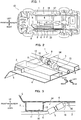
FIG. 1 is a bottom view illustrating a vehicle adopting a vehicle body structure of an embodiment; -
FIG. 2 is an enlarged perspective view of a connector and the periphery thereof; and -
FIG. 3 is a sectional view of a connector and the periphery thereof. - Description will now be made in relation to a vehicle body structure according to an embodiment with reference to the accompanying drawings. The following embodiment is merely exemplary and does not intend to exclude various modifications and application of another technique that are not explicitly suggested in the description. Each element of the embodiment can be variously modified and carried out without departing from the concept of the embodiment. The elements of the embodiment can be selected or omitted according to the requirement and can also be combined occasionally.
- The vehicle body structure of the present embodiment is applied to a
vehicle 10 illustrated inFIG. 1 . Under the floor of thevehicle 10, a resin tank storing an additive (e.g., aqueous urea or ammonia solution) for a urea Selective Catalytic Reduction system (urea SCR system). A urea SCR system is one of the types of exhaust-gas purifying system that purifies nitrogen oxides (NOx) contained in the exhaust gas from the engine. The urea SCR system of the present embodiment is configured by disposingaqueous urea injector 8 upstream of the NOx selective reduction catalyst interposed in an exhaust-air path and routing thepipe 6 through which the tank 7 is connected to theaqueous urea injector 8. The aqueous urea injected from theaqueous urea injector 8 becomes ammonia by hydrolysis, and the resultant ammonia serves as a reduction agent that reduces NOx in the exhaust gas to nitrogen on the catalyst. A urea SCR system of this type is widely used in, for example, a vehicle, a construction machine, a ship, a power plant utilizing a diesel engine or a lean-burn engine. - The
pipe 6 is routed on a side of a bottom face 19 (lower side) of afloor panel 4 of thevehicle 10. Thefloor panel 4 is a flat member serving as the floor of the vehicle interior. Adash panel 5, which partitions the vehicle interior from the engine room, is arranged so as to stand on the front end portion of thefloor panel 4. Thedash panel 5 extends diagonally upwards in the forward direction from thefloor panel 4. Thefloor panel 4 and thedash panel 5 may be formed independently from each other or may be of an integral form (e.g., formed by bending a single plate). In cases where thefloor panel 4 anddash panel 5 are of independent forms, across member 1 is disposed on a boundary between thefloor panel 4 and thedash panel 5. In contrast, in cases where thefloor panel 4 and thedash panel 5 are of an integral form, thedash panel 5 is partitioned from thefloor panel 4 on the basis of the position of thecross member 1, as illustrated inFIG. 2 . In either case, thecross member 1 is disposed at the front end portion of the floor panel 4 (in other words, the rear end portion of the dash panel 5). - On the side of the
bottom face 19 of thefloor panel 4, the cross member 1 (front floor cross member) andside members 2 are disposed which function as frame members of the vehicle body. Thecross member 1 is disposed so as to extend in the width (right-to-left) direction of thevehicle 10; and theside members 2 are disposed so as to extend in the front-to-rear direction of thevehicle 10. As illustrated inFIG. 1 , a pair ofside members 2 of the present embodiment are disposed at positions slightly inside from the left side face and the right side face of thevehicle 10 so as to be spaced apart in the width direction of thevehicle 10 from each other. Thecross member 1 is arranged so as to be connected to the left andright side members 2 at the front end portion of thefloor panel 4. Preferably, thecross member 1 penetrates bothside members 2 and extends to the outer side of theside members 2. This allows thefloor panel 4 to be supported by thecross member 1 over the entire width. - The
cross member 1 and theside members 2 are formed into respective shapes protruding downwards from thefloor panel 4. Thecross member 1 is integrated withfloor panel 4 by welding the rail member of the hat-shaped section opened upward to thebottom face 19 of thefloor panel 4. Likewise, eachside member 2 is integrated withfloor panel 4 by welding the rail member of the hat-shaped section opened upward to thebottom face 19 of thefloor panel 4. The height of the cross member 1 (the length from thebottom face 19 of thefloor panel 4 to abottom face 11 of the cross member 1) is set to be smaller than the height of each side member 2 (the length from thebottom face 19 of thefloor panel 4 to the bottom face of the side member 2). - The portion from the middle to the rear end of the
floor panel 4 in the front-to-rear direction is supported by a rearfloor cross member 17. The rearfloor cross member 17 is disposed behind thecross member 1 so as to be spaced apart from thecross member 1 in the front-to-rear direction and extends in the width direction of thevehicle 10. With this configuration, thebottom face 19 of thefloor panel 4 is supported crosswise by thecross member 1, the pair ofside members 2, and the rearfloor cross member 17, so that the stiffness and the strength of the floor face of the vehicle interior are ensured. A fuel tank is disposed behind the rearfloor cross member 17 and the shaft of the rear wheels are disposed behind the fuel tank. Behind the shaft of the rear wheels, a silencer (muffler) which is disposed at the rear end portion of the exhaust air path, and an additive tank 7 are arranged in parallel with each other with respect to the width direction of thevehicle 10. - Along the center of the
floor panel 4 with respect to the width direction of thevehicle 10, a backbone 18 (swelling portion) being in the form of a tunnel extending in the front-to-rear direction and swelling towards the vehicle interior is formed. A drive shaft that transmits the driving force to the rear wheels and the exhaust-air path (exhaust pipe) are arranged under thebackbone 18. Abackbone side member 3, which is spaced apart from theright side member 2 in the width direction of the vehicle and which extends in the front-to-rear direction, is disposed between thebackbone 18 and theside member 2 when seen from the bottom of thevehicle 10. - The
backbone side member 3 is a rail member having a hat-shaped section opened upwards and is welded to thebottom face 19 of thefloor panel 4. In the present embodiment, the front end portion of thebackbone side member 3 is connected to thecross member 1 while the rear end portion of thebackbone side member 3 is connected to the rearfloor cross member 17. The height of the backbone side member 3 (the length from thebottom face 19 of thefloor panel 4 to the bottom face of the backbone side member 3) is set about the same as the height of the cross member 1 (the length from thebottom face 19 of thefloor panel 4 to abottom face 11 of the cross member 1). -
FIG. 2 is a perspective view illustrating thebottom face 19 of thefloor panel 4 upside. Thepipe 6 is arranged so as to pass through a longitudinal space surrounded by theside member 2, thebackbone side member 3, and thefloor panel 4. In thestep portion 14 defined by thecross member 1 and thefloor panel 4, aconnector 9 that detachably connects thepipe 6 is disposed. Thestep portion 14 here is a space behind therear face 12 of thecross member 1, below thebottom face 19 of thefloor panel 4 and sandwiched by theright side member 2 and thebackbone side member 3. - The
connector 9 is a one-touch joint that can be easily connected and disconnected by hand. Theconnector 9 has a male or female fitting portion at the tip and the fitting portion has an outer circumference set larger than that of thepipe 6. Theconnector 9 is disposed adjacently to the front end portions of theside member 2 and thebackbone side member 3 in a portion behind thecross member 1, and is disposed between theside member 2 and thebackbone side member 3. Here, the front end portion is a portion at least ahead of the midway between thecross member 1 and the rearfloor cross member 17. - As illustrated in
FIG. 3 , thepipe 6 is fixed to the vehicle body at two points sandwiching theconnector 9 with afirst fixer 15 and asecond fixer 16. Specifically, thefirst fixer 15 fixes thepipe 6 to thebottom face 19 of thefloor panel 4 at a portion behind theconnector 9 while thesecond fixer 16 fixes thepipe 6 to thebottom face 11 of thecross member 1 at a portion ahead of theconnector 9. Thefirst fixer 15 andsecond fixer 16 are fixing bands made of metal or resin. - Each of the
first fixer 15 and thesecond fixer 16 includes a ring portion wrapped around the circumference of thepipe 6 and a fixing portion fixed to the vehicle body. The fixing portion of thefirst fixer 15 is fixed to a stud drooping from thefloor panel 4. The fixing portion of thesecond fixer 16 is fixed by being placed in an installing hole formed on thebottom face 11 of thecross member 1. Alternatively, thefirst fixer 15 and thesecond fixer 16 may be fixed to the vehicle body in any known manner except to the above. - As illustrated in
FIG. 3 , theconnector 9 is arranged so as to obliquely connect (extend between) thebottom face 11 of thecross member 1 and thebottom face 19 of thefloor panel 4 when seen from the side of the vehicle. In other words, thepipe 6 is not routed in a crank manner along the shape of thestep portion 14, but is obliquely routed so as to pass the shortest route from thebottom face 11 of thecross member 1 to the position of thefirst fixer 15. Inclining the route path of thepipe 6 in thestep portion 14 as the above prevents the outer circumference of theconnector 9 from interfering with thefloor panel 4, so that theconnector 9 is inhibited from being constrained. - As illustrated with the broken lines in
FIG. 1 , an undercover 20 is installed to the rectangular portion surrounded by thecross member 1, theside member 2, thebackbone side member 3, and the rearfloor cross member 17 when seen from the bottom of thevehicle 10. The undercover 20 planarly covers the lower portions of thepipe 6 and theconnector 9. The circumference edge of the undercover 20 is fixed to, for example, thecross member 1, theside member 2, thebackbone side member 3, and the rearfloor cross member 17. This effectively prohibit chipping abrasion and deformation due to a ricocheted rock from the road and soiling due to mud fluid, so that the protectability of theconnector 9 andpipe 6 can be enhanced. -
- (1) Interposing the
connector 9 in thepipe 6 can easily separate a forward pipe portion (a portion connected to the aqueous urea injector 8) installed at a position near to the engine from a rear pipe portion (a portion connected to the tank 7) installed at a position distant from the engine. This configuration allows the forward pipe portion to be installed to the engine assembly in the process of assembling the engine and also allows the rear pipe portion to be installed to the vehicle body in the process of assembling the vehicle body. Accordingly, the fittability of thepipe 6 can be enhanced. In addition to the above, arranging theconnector 9 in thestep portion 14 inhibits the outer circumference of theconnector 9 from interfering with thefloor panel 4, so that the protectability of theconnector 9 and thepipe 6 can be enhanced. - (2) Since the
connector 9 is arranged adjacently to the front end portion of theside member 2, which has relatively high stiffness among various parts of the vehicle body, theconnector 9 can be protected in cases where an external load is applied to the vehicle body. Consequently, the protectability of theconnector 9 and thepipe 6 can be enhanced. The side portions of thestep portion 14 can be protected by theside member 2, so that theconnector 9 can be escaped from being deformed or broken by a ricocheted rock from the road. Consequently, the protectability of theconnector 9 and thepipe 6 can be enhanced. - (3) The
connector 9 is disposed in a space sandwiched by theside member 2 and thebackbone side member 3. Theside member 2 and thebackbone side member 3 make it possible to further enhance the stiffness of thestep portion 14, so that the protectability of theconnector 9 and thepipe 6 can be enhanced. The side portion of thestep portion 14 can be covered with theside member 2 and thebackbone side member 3, so that theconnector 9 can be more surely escaped from being deformed or broken. Consequently, the protectability of theconnector 9 and thepipe 6 can be enhanced. - (4) As illustrated in
FIG. 3 , obliquely routing theconnector 9 when seen from the side can prevent the outer circumference of theconnector 9 from interfering with thefloor panel 4, so that the protectability of theconnector 9 and thepipe 6 can be enhanced. Additionally, since thepipe 6 is routed so as to pass the shortest route from thebottom face 11 of thecross member 1 to the position of thefirst fixer 15, the occurrence of slack and deviation of thepipe 6 can be suppressed. Consequently, the protectability of theconnector 9 and thepipe 6 can be enhanced. - (5) The
first fixer 15 is fixed to thebottom face 19 of thefloor panel 4 and thesecond fixer 16 is fixed to thebottom face 11 of thecross member 1. Arranging two fixers (i.e., thefirst fixer 15 and the second fixer 16) ahead and behind theconnector 9 can stabilize the state of fixing theconnector 9 to the vehicle body, so that the protectability of theconnector 9 can be enhanced. In addition to the above, fixing thepipe 6 at two positions different in height can easily incline the routing shape of theconnector 9 when seen from the side, so that the protectability of theconnector 9 and thepipe 6 can be further enhanced. - The description of the above embodiment is made in relation to a urea SCR system, but the additive conveyed through the
pipe 6 is not limited to aqueous urea. An exhaust-gas purifying system using a NOx selective reduction catalyst sometimes uses ammonia solution in place of the aqueous urea. An exhaust-gas purifying system using a diesel particulate filter (DPF) may inject hydrocarbon (HC, unburned fuel) into the exhaust pipe in order to encourage particulate matter (PC) to burn. Accordingly, the above vehicle body structure can be applied to an exhaust-gas purifying system supplying ammonia or hydrocarbon in place of aqueous urea. - The invention thus described, it will be obvious that the same may be varied in many ways. Such variations are not to be regarded as a departure from the scope of the invention, and all such modifications as would be obvious to one skilled in the art are intended to be included within the scope of the following claims.
-
- 1
- cross member
- 2
- side member
- 3
- backbone side member
- 4
- floor panel
- 5
- dash panel
- 6
- pipe
- 7
- tank
- 8
- aqueous urea injector
- 9
- connector
- 10
- vehicle
- 11
- bottom face
- 12
- rear face
- 14
- step portion
- 15
- first fixer
- 16
- second fixer
- 17
- rear floor cross member
- 18
- backbone
- 19
- bottom face
- 20
- under cover
Claims (5)
- A vehicle body structure comprising:a floor panel (4) that forms a floor of a vehicle (10);a pipe (6) that is disposed adjacently to a lower face (19) of the floor panel (4) and that serves as a path for supplying an additive for purifying exhaust gas;a cross member (1) that protrudes downwards from the floor panel (4) and that extends in a width direction of the vehicle (10); anda connector (9) that is disposed in a step portion (14) defined by the cross member (1) and the floor panel (4) and that detachably connects the pipe (6).
- The vehicle body structure according to claim 1, further comprises a side member (2) that protrudes downwards from the floor panel (4), that is connected to the cross member (1), and that extends in a front-to-rear direction of the vehicle (10), wherein the connector (9) is disposed behind the cross member (1) and adjacently to a front portion of the side member (2).
- The vehicle body structure according to claim 2, further comprises a backbone side member (3) that is spaced apart from the side member (2) with respect to the width direction, that extends along the front-to-rear direction of the vehicle (10), and that is connected to the cross member (1), wherein the connector (9) is disposed between the side member (2) and the backbone side member (3) when seen from a bottom of the vehicle (10).
- The vehicle body structure according to any one of claims 1-3, wherein the connector (9) is disposed so as to obliquely connect a bottom face (11) of the cross member (1) and the bottom face (19) of the floor panel (4) when seen from a side of the vehicle (10).
- The vehicle body structure according to any one of claims 1-4, further comprising:a first fixer (15) that fixes the pipe (6) to the floor panel (4) at a portion behind the connector (9) of the vehicle (6); anda second fixer (16) that fixes the pipe (10) to the cross member (6) at a portion ahead of the connector (9) of the vehicle (10).
Applications Claiming Priority (1)
| Application Number | Priority Date | Filing Date | Title |
|---|---|---|---|
| JP2016246338A JP6662281B2 (en) | 2016-12-20 | 2016-12-20 | Body structure |
Publications (2)
| Publication Number | Publication Date |
|---|---|
| EP3339593A1 true EP3339593A1 (en) | 2018-06-27 |
| EP3339593B1 EP3339593B1 (en) | 2019-04-03 |
Family
ID=60574379
Family Applications (1)
| Application Number | Title | Priority Date | Filing Date |
|---|---|---|---|
| EP17203439.9A Active EP3339593B1 (en) | 2016-12-20 | 2017-11-24 | Vehicle body structure |
Country Status (2)
| Country | Link |
|---|---|
| EP (1) | EP3339593B1 (en) |
| JP (1) | JP6662281B2 (en) |
Citations (4)
| Publication number | Priority date | Publication date | Assignee | Title |
|---|---|---|---|---|
| JP2009108850A (en) * | 2007-10-12 | 2009-05-21 | Mazda Motor Corp | Vehicle exhaust purification device arrangement structure |
| WO2011085154A1 (en) * | 2010-01-08 | 2011-07-14 | Parker-Hannifin Corporation | Electrically-heated hose assembly for selective catalytic reduction (scr) systems |
| US20130220470A1 (en) * | 2012-02-29 | 2013-08-29 | Ti Automotive (Fuldabruck) Gmbh | Connector with pressure equalization |
| US20150232127A1 (en) * | 2014-02-14 | 2015-08-20 | Toyota Jidosha Kabushiki Kaisha | Vehicle body lower structure |
Family Cites Families (3)
| Publication number | Priority date | Publication date | Assignee | Title |
|---|---|---|---|---|
| JP2009221884A (en) * | 2008-03-13 | 2009-10-01 | Mazda Motor Corp | Tank arrangement structure for vehicle |
| JP2012111281A (en) * | 2010-11-22 | 2012-06-14 | Suzuki Motor Corp | Fuel piping structure for vehicle |
| JP6281203B2 (en) * | 2013-08-01 | 2018-02-21 | いすゞ自動車株式会社 | Cross member |
-
2016
- 2016-12-20 JP JP2016246338A patent/JP6662281B2/en active Active
-
2017
- 2017-11-24 EP EP17203439.9A patent/EP3339593B1/en active Active
Patent Citations (4)
| Publication number | Priority date | Publication date | Assignee | Title |
|---|---|---|---|---|
| JP2009108850A (en) * | 2007-10-12 | 2009-05-21 | Mazda Motor Corp | Vehicle exhaust purification device arrangement structure |
| WO2011085154A1 (en) * | 2010-01-08 | 2011-07-14 | Parker-Hannifin Corporation | Electrically-heated hose assembly for selective catalytic reduction (scr) systems |
| US20130220470A1 (en) * | 2012-02-29 | 2013-08-29 | Ti Automotive (Fuldabruck) Gmbh | Connector with pressure equalization |
| US20150232127A1 (en) * | 2014-02-14 | 2015-08-20 | Toyota Jidosha Kabushiki Kaisha | Vehicle body lower structure |
Also Published As
| Publication number | Publication date |
|---|---|
| JP2018099961A (en) | 2018-06-28 |
| EP3339593B1 (en) | 2019-04-03 |
| JP6662281B2 (en) | 2020-03-11 |
Similar Documents
| Publication | Publication Date | Title |
|---|---|---|
| US9777611B2 (en) | Construction machine | |
| JP4928388B2 (en) | Exhaust purification device | |
| JP4826612B2 (en) | Vehicle exhaust purification device arrangement structure | |
| CN101175906B (en) | Exhaust gas purification device for engine | |
| EP3222830B1 (en) | Industrial vehicle | |
| EP3235774B1 (en) | Rough terrain crane | |
| EP3235674B1 (en) | Rough terrain crane | |
| EP3339593B1 (en) | Vehicle body structure | |
| JP5054613B2 (en) | Engine exhaust gas purification device | |
| JP2009150337A (en) | Exhaust emission control device for engine | |
| KR20190135560A (en) | Work vehicle | |
| JP6066056B2 (en) | Vehicle tank structure | |
| JP6908340B2 (en) | Work vehicle and exhaust purification device for work vehicle | |
| EP3339073B1 (en) | Vehicle body structure | |
| EP3339074B1 (en) | Vehicle body structure | |
| EP3173275B1 (en) | Tank arrangement structure | |
| JP6672956B2 (en) | Additive container | |
| CN105386829B (en) | The motor vehicle of reducing agent tank with caudal | |
| JP2018100611A (en) | Body structure | |
| JP6880836B2 (en) | Body structure | |
| JP2018099981A (en) | Body structure | |
| JP2024126251A (en) | Tank support structure | |
| JP2017149226A (en) | Vehicle body structure | |
| JP2009167869A (en) | Exhaust system structure | |
| JP2018162684A (en) | Protective cover for reducing agent addition device |
Legal Events
| Date | Code | Title | Description |
|---|---|---|---|
| PUAI | Public reference made under article 153(3) epc to a published international application that has entered the european phase |
Free format text: ORIGINAL CODE: 0009012 |
|
| STAA | Information on the status of an ep patent application or granted ep patent |
Free format text: STATUS: THE APPLICATION HAS BEEN PUBLISHED |
|
| AK | Designated contracting states |
Kind code of ref document: A1 Designated state(s): AL AT BE BG CH CY CZ DE DK EE ES FI FR GB GR HR HU IE IS IT LI LT LU LV MC MK MT NL NO PL PT RO RS SE SI SK SM TR |
|
| AX | Request for extension of the european patent |
Extension state: BA ME |
|
| STAA | Information on the status of an ep patent application or granted ep patent |
Free format text: STATUS: REQUEST FOR EXAMINATION WAS MADE |
|
| 17P | Request for examination filed |
Effective date: 20180718 |
|
| RBV | Designated contracting states (corrected) |
Designated state(s): AL AT BE BG CH CY CZ DE DK EE ES FI FR GB GR HR HU IE IS IT LI LT LU LV MC MK MT NL NO PL PT RO RS SE SI SK SM TR |
|
| RIC1 | Information provided on ipc code assigned before grant |
Ipc: F01N 3/20 20060101AFI20180913BHEP Ipc: F01N 13/18 20100101ALI20180913BHEP Ipc: B62D 21/03 20060101ALI20180913BHEP |
|
| GRAP | Despatch of communication of intention to grant a patent |
Free format text: ORIGINAL CODE: EPIDOSNIGR1 |
|
| STAA | Information on the status of an ep patent application or granted ep patent |
Free format text: STATUS: GRANT OF PATENT IS INTENDED |
|
| INTG | Intention to grant announced |
Effective date: 20181024 |
|
| GRAS | Grant fee paid |
Free format text: ORIGINAL CODE: EPIDOSNIGR3 |
|
| GRAA | (expected) grant |
Free format text: ORIGINAL CODE: 0009210 |
|
| STAA | Information on the status of an ep patent application or granted ep patent |
Free format text: STATUS: THE PATENT HAS BEEN GRANTED |
|
| AK | Designated contracting states |
Kind code of ref document: B1 Designated state(s): AL AT BE BG CH CY CZ DE DK EE ES FI FR GB GR HR HU IE IS IT LI LT LU LV MC MK MT NL NO PL PT RO RS SE SI SK SM TR |
|
| REG | Reference to a national code |
Ref country code: GB Ref legal event code: FG4D |
|
| REG | Reference to a national code |
Ref country code: CH Ref legal event code: EP Ref country code: AT Ref legal event code: REF Ref document number: 1116019 Country of ref document: AT Kind code of ref document: T Effective date: 20190415 |
|
| REG | Reference to a national code |
Ref country code: DE Ref legal event code: R096 Ref document number: 602017003087 Country of ref document: DE |
|
| REG | Reference to a national code |
Ref country code: IE Ref legal event code: FG4D |
|
| RAP2 | Party data changed (patent owner data changed or rights of a patent transferred) |
Owner name: MITSUBISHI JIDOSHA ENGINEERING K.K. Owner name: MITSUBISHI JIDOSHA KOGYO KABUSHIKI KAISHA |
|
| REG | Reference to a national code |
Ref country code: NL Ref legal event code: MP Effective date: 20190403 |
|
| REG | Reference to a national code |
Ref country code: LT Ref legal event code: MG4D |
|
| REG | Reference to a national code |
Ref country code: AT Ref legal event code: MK05 Ref document number: 1116019 Country of ref document: AT Kind code of ref document: T Effective date: 20190403 |
|
| PG25 | Lapsed in a contracting state [announced via postgrant information from national office to epo] |
Ref country code: NL Free format text: LAPSE BECAUSE OF FAILURE TO SUBMIT A TRANSLATION OF THE DESCRIPTION OR TO PAY THE FEE WITHIN THE PRESCRIBED TIME-LIMIT Effective date: 20190403 |
|
| PG25 | Lapsed in a contracting state [announced via postgrant information from national office to epo] |
Ref country code: ES Free format text: LAPSE BECAUSE OF FAILURE TO SUBMIT A TRANSLATION OF THE DESCRIPTION OR TO PAY THE FEE WITHIN THE PRESCRIBED TIME-LIMIT Effective date: 20190403 Ref country code: PT Free format text: LAPSE BECAUSE OF FAILURE TO SUBMIT A TRANSLATION OF THE DESCRIPTION OR TO PAY THE FEE WITHIN THE PRESCRIBED TIME-LIMIT Effective date: 20190803 Ref country code: LT Free format text: LAPSE BECAUSE OF FAILURE TO SUBMIT A TRANSLATION OF THE DESCRIPTION OR TO PAY THE FEE WITHIN THE PRESCRIBED TIME-LIMIT Effective date: 20190403 Ref country code: CZ Free format text: LAPSE BECAUSE OF FAILURE TO SUBMIT A TRANSLATION OF THE DESCRIPTION OR TO PAY THE FEE WITHIN THE PRESCRIBED TIME-LIMIT Effective date: 20190403 Ref country code: FI Free format text: LAPSE BECAUSE OF FAILURE TO SUBMIT A TRANSLATION OF THE DESCRIPTION OR TO PAY THE FEE WITHIN THE PRESCRIBED TIME-LIMIT Effective date: 20190403 Ref country code: HR Free format text: LAPSE BECAUSE OF FAILURE TO SUBMIT A TRANSLATION OF THE DESCRIPTION OR TO PAY THE FEE WITHIN THE PRESCRIBED TIME-LIMIT Effective date: 20190403 Ref country code: SE Free format text: LAPSE BECAUSE OF FAILURE TO SUBMIT A TRANSLATION OF THE DESCRIPTION OR TO PAY THE FEE WITHIN THE PRESCRIBED TIME-LIMIT Effective date: 20190403 Ref country code: AL Free format text: LAPSE BECAUSE OF FAILURE TO SUBMIT A TRANSLATION OF THE DESCRIPTION OR TO PAY THE FEE WITHIN THE PRESCRIBED TIME-LIMIT Effective date: 20190403 Ref country code: NO Free format text: LAPSE BECAUSE OF FAILURE TO SUBMIT A TRANSLATION OF THE DESCRIPTION OR TO PAY THE FEE WITHIN THE PRESCRIBED TIME-LIMIT Effective date: 20190703 |
|
| PG25 | Lapsed in a contracting state [announced via postgrant information from national office to epo] |
Ref country code: PL Free format text: LAPSE BECAUSE OF FAILURE TO SUBMIT A TRANSLATION OF THE DESCRIPTION OR TO PAY THE FEE WITHIN THE PRESCRIBED TIME-LIMIT Effective date: 20190403 Ref country code: LV Free format text: LAPSE BECAUSE OF FAILURE TO SUBMIT A TRANSLATION OF THE DESCRIPTION OR TO PAY THE FEE WITHIN THE PRESCRIBED TIME-LIMIT Effective date: 20190403 Ref country code: GR Free format text: LAPSE BECAUSE OF FAILURE TO SUBMIT A TRANSLATION OF THE DESCRIPTION OR TO PAY THE FEE WITHIN THE PRESCRIBED TIME-LIMIT Effective date: 20190704 Ref country code: BG Free format text: LAPSE BECAUSE OF FAILURE TO SUBMIT A TRANSLATION OF THE DESCRIPTION OR TO PAY THE FEE WITHIN THE PRESCRIBED TIME-LIMIT Effective date: 20190703 Ref country code: RS Free format text: LAPSE BECAUSE OF FAILURE TO SUBMIT A TRANSLATION OF THE DESCRIPTION OR TO PAY THE FEE WITHIN THE PRESCRIBED TIME-LIMIT Effective date: 20190403 |
|
| PG25 | Lapsed in a contracting state [announced via postgrant information from national office to epo] |
Ref country code: AT Free format text: LAPSE BECAUSE OF FAILURE TO SUBMIT A TRANSLATION OF THE DESCRIPTION OR TO PAY THE FEE WITHIN THE PRESCRIBED TIME-LIMIT Effective date: 20190403 Ref country code: IS Free format text: LAPSE BECAUSE OF FAILURE TO SUBMIT A TRANSLATION OF THE DESCRIPTION OR TO PAY THE FEE WITHIN THE PRESCRIBED TIME-LIMIT Effective date: 20190803 |
|
| REG | Reference to a national code |
Ref country code: DE Ref legal event code: R097 Ref document number: 602017003087 Country of ref document: DE |
|
| PG25 | Lapsed in a contracting state [announced via postgrant information from national office to epo] |
Ref country code: SK Free format text: LAPSE BECAUSE OF FAILURE TO SUBMIT A TRANSLATION OF THE DESCRIPTION OR TO PAY THE FEE WITHIN THE PRESCRIBED TIME-LIMIT Effective date: 20190403 Ref country code: RO Free format text: LAPSE BECAUSE OF FAILURE TO SUBMIT A TRANSLATION OF THE DESCRIPTION OR TO PAY THE FEE WITHIN THE PRESCRIBED TIME-LIMIT Effective date: 20190403 Ref country code: EE Free format text: LAPSE BECAUSE OF FAILURE TO SUBMIT A TRANSLATION OF THE DESCRIPTION OR TO PAY THE FEE WITHIN THE PRESCRIBED TIME-LIMIT Effective date: 20190403 Ref country code: DK Free format text: LAPSE BECAUSE OF FAILURE TO SUBMIT A TRANSLATION OF THE DESCRIPTION OR TO PAY THE FEE WITHIN THE PRESCRIBED TIME-LIMIT Effective date: 20190403 |
|
| PLBE | No opposition filed within time limit |
Free format text: ORIGINAL CODE: 0009261 |
|
| STAA | Information on the status of an ep patent application or granted ep patent |
Free format text: STATUS: NO OPPOSITION FILED WITHIN TIME LIMIT |
|
| PG25 | Lapsed in a contracting state [announced via postgrant information from national office to epo] |
Ref country code: SM Free format text: LAPSE BECAUSE OF FAILURE TO SUBMIT A TRANSLATION OF THE DESCRIPTION OR TO PAY THE FEE WITHIN THE PRESCRIBED TIME-LIMIT Effective date: 20190403 Ref country code: IT Free format text: LAPSE BECAUSE OF FAILURE TO SUBMIT A TRANSLATION OF THE DESCRIPTION OR TO PAY THE FEE WITHIN THE PRESCRIBED TIME-LIMIT Effective date: 20190403 |
|
| 26N | No opposition filed |
Effective date: 20200106 |
|
| PG25 | Lapsed in a contracting state [announced via postgrant information from national office to epo] |
Ref country code: TR Free format text: LAPSE BECAUSE OF FAILURE TO SUBMIT A TRANSLATION OF THE DESCRIPTION OR TO PAY THE FEE WITHIN THE PRESCRIBED TIME-LIMIT Effective date: 20190403 |
|
| PG25 | Lapsed in a contracting state [announced via postgrant information from national office to epo] |
Ref country code: SI Free format text: LAPSE BECAUSE OF FAILURE TO SUBMIT A TRANSLATION OF THE DESCRIPTION OR TO PAY THE FEE WITHIN THE PRESCRIBED TIME-LIMIT Effective date: 20190403 |
|
| PG25 | Lapsed in a contracting state [announced via postgrant information from national office to epo] |
Ref country code: LU Free format text: LAPSE BECAUSE OF NON-PAYMENT OF DUE FEES Effective date: 20191124 Ref country code: MC Free format text: LAPSE BECAUSE OF FAILURE TO SUBMIT A TRANSLATION OF THE DESCRIPTION OR TO PAY THE FEE WITHIN THE PRESCRIBED TIME-LIMIT Effective date: 20190403 |
|
| REG | Reference to a national code |
Ref country code: BE Ref legal event code: MM Effective date: 20191130 |
|
| PG25 | Lapsed in a contracting state [announced via postgrant information from national office to epo] |
Ref country code: IE Free format text: LAPSE BECAUSE OF NON-PAYMENT OF DUE FEES Effective date: 20191124 |
|
| PG25 | Lapsed in a contracting state [announced via postgrant information from national office to epo] |
Ref country code: BE Free format text: LAPSE BECAUSE OF NON-PAYMENT OF DUE FEES Effective date: 20191130 |
|
| PG25 | Lapsed in a contracting state [announced via postgrant information from national office to epo] |
Ref country code: CY Free format text: LAPSE BECAUSE OF FAILURE TO SUBMIT A TRANSLATION OF THE DESCRIPTION OR TO PAY THE FEE WITHIN THE PRESCRIBED TIME-LIMIT Effective date: 20190403 |
|
| REG | Reference to a national code |
Ref country code: CH Ref legal event code: PL |
|
| PG25 | Lapsed in a contracting state [announced via postgrant information from national office to epo] |
Ref country code: HU Free format text: LAPSE BECAUSE OF FAILURE TO SUBMIT A TRANSLATION OF THE DESCRIPTION OR TO PAY THE FEE WITHIN THE PRESCRIBED TIME-LIMIT; INVALID AB INITIO Effective date: 20171124 Ref country code: MT Free format text: LAPSE BECAUSE OF FAILURE TO SUBMIT A TRANSLATION OF THE DESCRIPTION OR TO PAY THE FEE WITHIN THE PRESCRIBED TIME-LIMIT Effective date: 20190403 |
|
| PG25 | Lapsed in a contracting state [announced via postgrant information from national office to epo] |
Ref country code: LI Free format text: LAPSE BECAUSE OF NON-PAYMENT OF DUE FEES Effective date: 20201130 Ref country code: CH Free format text: LAPSE BECAUSE OF NON-PAYMENT OF DUE FEES Effective date: 20201130 |
|
| PG25 | Lapsed in a contracting state [announced via postgrant information from national office to epo] |
Ref country code: MK Free format text: LAPSE BECAUSE OF FAILURE TO SUBMIT A TRANSLATION OF THE DESCRIPTION OR TO PAY THE FEE WITHIN THE PRESCRIBED TIME-LIMIT Effective date: 20190403 |
|
| GBPC | Gb: european patent ceased through non-payment of renewal fee |
Effective date: 20211124 |
|
| PG25 | Lapsed in a contracting state [announced via postgrant information from national office to epo] |
Ref country code: GB Free format text: LAPSE BECAUSE OF NON-PAYMENT OF DUE FEES Effective date: 20211124 |
|
| PGFP | Annual fee paid to national office [announced via postgrant information from national office to epo] |
Ref country code: FR Payment date: 20250930 Year of fee payment: 9 |
|
| PGFP | Annual fee paid to national office [announced via postgrant information from national office to epo] |
Ref country code: DE Payment date: 20250930 Year of fee payment: 9 |