EP3339187A1 - Passenger boarding bridge - Google Patents
Passenger boarding bridge Download PDFInfo
- Publication number
- EP3339187A1 EP3339187A1 EP16380038.6A EP16380038A EP3339187A1 EP 3339187 A1 EP3339187 A1 EP 3339187A1 EP 16380038 A EP16380038 A EP 16380038A EP 3339187 A1 EP3339187 A1 EP 3339187A1
- Authority
- EP
- European Patent Office
- Prior art keywords
- bearing
- shoe
- guiding
- tunnel
- planar
- Prior art date
- Legal status (The legal status is an assumption and is not a legal conclusion. Google has not performed a legal analysis and makes no representation as to the accuracy of the status listed.)
- Granted
Links
- 238000005096 rolling process Methods 0.000 description 4
- 238000005260 corrosion Methods 0.000 description 2
- 230000007797 corrosion Effects 0.000 description 2
- 239000000314 lubricant Substances 0.000 description 2
- 238000012423 maintenance Methods 0.000 description 2
- 238000000034 method Methods 0.000 description 2
- 230000003068 static effect Effects 0.000 description 2
- 238000005452 bending Methods 0.000 description 1
- 239000000919 ceramic Substances 0.000 description 1
- 230000001419 dependent effect Effects 0.000 description 1
- 239000002783 friction material Substances 0.000 description 1
- 239000000463 material Substances 0.000 description 1
- 239000004033 plastic Substances 0.000 description 1
- 229920003023 plastic Polymers 0.000 description 1
Images


Classifications
-
- B—PERFORMING OPERATIONS; TRANSPORTING
- B64—AIRCRAFT; AVIATION; COSMONAUTICS
- B64F—GROUND OR AIRCRAFT-CARRIER-DECK INSTALLATIONS SPECIALLY ADAPTED FOR USE IN CONNECTION WITH AIRCRAFT; DESIGNING, MANUFACTURING, ASSEMBLING, CLEANING, MAINTAINING OR REPAIRING AIRCRAFT, NOT OTHERWISE PROVIDED FOR; HANDLING, TRANSPORTING, TESTING OR INSPECTING AIRCRAFT COMPONENTS, NOT OTHERWISE PROVIDED FOR
- B64F1/00—Ground or aircraft-carrier-deck installations
- B64F1/30—Ground or aircraft-carrier-deck installations for embarking or disembarking passengers
- B64F1/305—Bridges extending between terminal building and aircraft, e.g. telescopic, vertically adjustable
Definitions
- the invention refers to a passenger boarding bridge.
- a passenger boarding bridge of the claimed type connects an airplane with a terminal building via a tunnel.
- the tunnel may be extendible and comprises at least two tunnel sections, which can be telescoped for adjusting the length of the tunnel to the distance between an airplane door and the terminal building.
- the tunnel sections are connected by roller bearings to enable relative movement of the tunnel sections during telescoping.
- US 3,184,772 A discloses a conventional bearing concept, that uses rollers between the two tunnel sections.
- the inventive passenger boarding bridge comprises a tunnel having a first tunnel section and a second tunnel section, the tunnel sections can be telescoped for adjusting the length of the tunnel along a main sliding direction, a number of bearings adapted to slidably support the tunnel sections relative to each other, having at least one bearing rail connected to the first tunnel section and at least one bearing sledge connected to the second tunnel section.
- the bearing rail comprises a planar first horizontal bearing surface.
- the bearing sledge comprises a planar second horizontal bearing surface, which is adapted to slide along the planar first horizontal bearing surface during telescoping.
- the main idea is to replace the rolling rollers by a sliding sledge. Though the friction between the two tunnel sections may increase during telescoping, the surface pressure when static loads charges the bearings are massively reduced compared to the conventional roller bearings. This enables less wear, thus less corrosion and less maintenance costs. The increased friction is acceptable in view of the other advantages, also because during telescoping the bridge is not occupied by passengers and thus comparatively light in weight.
- the bearing sledge comprises a bearing support attached to the second tunnel and a bearing shoe carrying the second horizontal bearing surface, wherein the bearing shoe is tiltably connected to the bearing support, in particular by a first hinge.
- the ability to tilt provides a self-adjusting mechanism to the bearing shoe.
- the bearing shoe is tiltably connected to the bearing support along a first axis, which is aligned horizontally and perpendicular to the main sliding direction. This first axis corresponds to the axis of the main bending moments occurring in the tunnel sections during use.
- the bearing shoe is tiltably connected to the bearing support additionally along a second axis, which is aligned horizontally and parallel to the main sliding direction, and/or along a third vertical axis. This additionally enables a self-adjusting capability of the bearing shoe in any other direction.
- the bearing rail comprises a planar first vertical guiding surface
- the bearing sledge comprises a planar second vertical guiding surface, which is in slidable contact with the planar first vertical guiding surface.
- the planar surfaces reduce the pressure stress on the guiding surfaces and enable also less wear.
- the bearing sledge comprises a guiding support attached to the second tunnel and a guiding shoe carrying the second vertical guiding surface.
- the guiding shoe is tiltably connected to the guiding support, in particular by a first hinge and/or by a second hinge. The tiltably connection enables a self-adjusting mechanism to the second vertical guiding surfaces.
- the guiding support can be the same part as the previously mentioned bearing support.
- the guiding shoe is tiltably connected to the guiding support along a first axis, which is aligned horizontally and perpendicular to the main sliding direction.
- the bearing shoe is in particular tiltably connected to the bearing support along a second axis, which is aligned horizontally and parallel to the main sliding direction and/or along a third vertical axis.
- the bearing shoe and/or the guiding shoe is connected to the bearing support by means of a first ball joint.
- the ball joint enables that the bearing shoe and/or the guiding shoe may tilt around all spatial axis.
- the guiding shoe is connected to the bearing shoe by means of a second ball joint.
- the bearing shoe carries the guiding shoe. So in principal the guiding shoe has the same degrees of freedom as the bearing shoe relative to the bearing support. Through the second ball joint the guiding shoe has also additional degrees of freedom relative to the bearing shoe. This enables optimum self-alignment capabilities between all involved surfaces.
- the bearing surfaces of one bearing having at least a common planar contacting area of at least 20 cm 2 , in particular at least 25cm 2 .
- the contacting area means, the common surface area of the first horizontal bearing and the second horizontal bearing surface, being in contacting to each other and being capable of transmitting normal force to each other by surface pressure.
- Some of the surfaces may be made from a low friction material, e.g. so called low friction ceramics or so called low friction plastics, which are advantageous due to their low friction coefficient. Since the surface pressure is much lower compared to rollers, materials having a less hardness can be used.
- tiltably means, that the respective parts can be twisted relative to each other over a range of angle which is much less than 90°.
- the tilting is just provided for adjusting the planar bearing surface to each other (making them parallel), therefore a twisting is only necessary of some degrees smaller than 10°.
- roller bearings wherein the rollers can rotate multiple times 360°. Twisting is not rolling; rolling means that a rotational body can perform multiple rotations over an angle of more than 360°.
- FIG. 1 shows a part of an inventive passenger boarding bridge 1, as in principal is disclosed e.g. in WO 2014/146758 A1 .
- the passenger boarding bridge 1 comprises an extendible tunnel 2, having two tunnel sections 3, 4 which can be telescoped along a main sliding direction D.
- the tunnel sections are supported to each other by means of in sum eight bearings 5, which are subsequently described in more detail.
- a bearing 5 comprises a bearing sledge 10, which can slide along a bearing rail 6.
- the bearing rail 6 has a planar first horizontal bearing surface 7.
- the bearing rail 6 is mounted to the first tunnel section 3
- the bearing sledge 10 is mounted to the second tunnel section 4.
- the bearing sledge 10 has a planar second horizontal bearing surface 13, which rests on the planar first horizontal bearing surface 7.
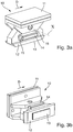
- FIG. 3 shows details of the bearing sledge 10.
- the planar second horizontal bearing surface 13 defines an area of contact between the bearing sledge 10 and the bearing rail 6. Because there is a planar contact between the surfaces, the surface pressure is massively reduced compared to the conventional roller bearings having a curved second bearing surface.
- the slide friction of the inventive bearing concept may be slightly higher compared to the rolling friction of the prior art roller bearings.
- the main use of a passenger boarding bridge is more a static use, in which no telescoping procedure is given; the dynamic use during telescoping is limited to some minutes per day when the bridge is tob connected to the airplane or to be disconnected from the airplane. So the disadvantage of higher friction can be accepted, also since the bridge is unloaded during (dis-)connection.
- a lateral guiding is provided by the provision of a planar first vertical guiding surface 8 of the bearing rail 6 and a planar second vertical guiding surface 14 attached to the bearing sledge 10.
- Figure 3 and 4 shows, that the bearing sledge 10 comprises several components, including a bearing support 11 and a bearing shoe 12.
- the bearing support 11 is fixed to the second tunnel section 4, the bearing shoe 12 is attached to the bearing support 11 by means of a first ball joint 16.
- the first ball joint 16 enables a tilting of the bearing shoe 12 relative to the bearing support 11 primary along an axis X, which is aligned horizontally and perpendicular to the main sliding direction D. Additionally the first ball joint 16 enables a tilting of the bearing shoe 12 relative to the bearing support 11 along an axis Z, which is parallel to the main sliding direction D, and along a vertical axis Y.
- the first ball joint provides certain degrees of freedom for the first horizontal bearing surface 13 to optimally align with the planar first horizontal bearing surface 7 ( figure 5 ).
- the bearing sledge 10 further comprises a guiding shoe 15, carrying the second vertical guiding surface 14.
- the guiding shoe 15 is connected to the bearing shoe 12 by means of a second ball joint 17, enabling a tilting of the guiding shoe 15 relative to the bearing shoe 12 along a vertical axis Y.
- the guiding shoe 15 is attached to the bearing shoe 12 by means of a second ball joint 17. Due to the connection of the guiding shoe 15 at the bearing shoe 12 the guiding shoe 15 has the same degrees of freedom as the bearing shoe 12 relative to the bearing support 11.
- the second ball joint 17 enables a tilting of the guiding shoe 15 relative to the bearing shoe 12 primary along the axis Z, along the axis X and along the axis Y.
- the second ball joint 17 provides certain degrees of freedom for the planar second vertical guiding surface 14 to optimally align with the planar first vertical guiding surface 8.
- the second horizontal bearing surface 13 is constituted by a separate bearing slide pad, supported by the bearing shoe 12.
- the planar second vertical guiding surface 14 constituted by a separate guiding slide pad, supported by the guiding shoe 15.
Landscapes
- Engineering & Computer Science (AREA)
- Architecture (AREA)
- Civil Engineering (AREA)
- Structural Engineering (AREA)
- Mechanical Engineering (AREA)
- Aviation & Aerospace Engineering (AREA)
- Bridges Or Land Bridges (AREA)
Abstract
- a tunnel (2) having a first tunnel section (3) and a second tunnel section (4), the tunnel sections (3, 4) can be telescoped for adjusting the length of the tunnel (2) along a main sliding direction (D),
- a number of bearings (5) adapted to slidably support the tunnel sections (3, 4) relative to each other, having at least one bearing rail (6) connected to the first tunnel section (3) and at least one bearing sledge (10) connected to the second tunnel section (4), wherein the bearing rail (6) comprises a planar first horizontal bearing surface (7),
wherein the bearing sledge (10) comprises a planar second horizontal bearing surface (13), which is adapted to slide along the planar first horizontal bearing surface (7) during telescoping.
Description
- The invention refers to a passenger boarding bridge.
- A passenger boarding bridge of the claimed type, for example shown in
WO 2014/146758 A1 , connects an airplane with a terminal building via a tunnel. The tunnel may be extendible and comprises at least two tunnel sections, which can be telescoped for adjusting the length of the tunnel to the distance between an airplane door and the terminal building. The tunnel sections are connected by roller bearings to enable relative movement of the tunnel sections during telescoping.US 3,184,772 A discloses a conventional bearing concept, that uses rollers between the two tunnel sections. - However the forces onto the bearings are that high, that enormous wear is applicable to the rollers and the bearing surfaces. This is in main caused by the nearly point or line shaped contact surfaces of the rollers and the respective bearing surface, which causes high stress on the small contact surface. The stress is also a cause for increased corrosion on the bearing rail surfaces.
- It is an object of the present invention to reduce the wear caused in connection with the bearing of the tunnel sections. The object of the invention is solved by a passenger boarding bridge according to
claim 1; preferred embodiments are described in the dependent claims and the description. - The inventive passenger boarding bridge comprises a tunnel having a first tunnel section and a second tunnel section, the tunnel sections can be telescoped for adjusting the length of the tunnel along a main sliding direction, a number of bearings adapted to slidably support the tunnel sections relative to each other, having at least one bearing rail connected to the first tunnel section and at least one bearing sledge connected to the second tunnel section. The bearing rail comprises a planar first horizontal bearing surface. The bearing sledge comprises a planar second horizontal bearing surface, which is adapted to slide along the planar first horizontal bearing surface during telescoping.
- The main idea is to replace the rolling rollers by a sliding sledge. Though the friction between the two tunnel sections may increase during telescoping, the surface pressure when static loads charges the bearings are massively reduced compared to the conventional roller bearings. This enables less wear, thus less corrosion and less maintenance costs. The increased friction is acceptable in view of the other advantages, also because during telescoping the bridge is not occupied by passengers and thus comparatively light in weight.
- In an embodiment the bearing sledge comprises a bearing support attached to the second tunnel and a bearing shoe carrying the second horizontal bearing surface, wherein the bearing shoe is tiltably connected to the bearing support, in particular by a first hinge. The ability to tilt provides a self-adjusting mechanism to the bearing shoe. In particular the bearing shoe is tiltably connected to the bearing support along a first axis, which is aligned horizontally and perpendicular to the main sliding direction. This first axis corresponds to the axis of the main bending moments occurring in the tunnel sections during use.
- In an embodiment the bearing shoe is tiltably connected to the bearing support additionally along a second axis, which is aligned horizontally and parallel to the main sliding direction, and/or along a third vertical axis. This additionally enables a self-adjusting capability of the bearing shoe in any other direction.
- In an embodiment the bearing rail comprises a planar first vertical guiding surface, and the bearing sledge comprises a planar second vertical guiding surface, which is in slidable contact with the planar first vertical guiding surface. In particular during the side movement of the passenger boarding bridge heavy loads occur on the vertical guiding surfaces. The planar surfaces reduce the pressure stress on the guiding surfaces and enable also less wear.
- In an embodiment that the bearing sledge comprises a guiding support attached to the second tunnel and a guiding shoe carrying the second vertical guiding surface. The guiding shoe is tiltably connected to the guiding support, in particular by a first hinge and/or by a second hinge. The tiltably connection enables a self-adjusting mechanism to the second vertical guiding surfaces. In an embodiment the guiding support can be the same part as the previously mentioned bearing support.
- In an embodiment the guiding shoe is tiltably connected to the guiding support along a first axis, which is aligned horizontally and perpendicular to the main sliding direction. Additionally the bearing shoe is in particular tiltably connected to the bearing support along a second axis, which is aligned horizontally and parallel to the main sliding direction and/or along a third vertical axis. The advantages mentioned above are applicable.
- In an embodiment the bearing shoe and/or the guiding shoe is connected to the bearing support by means of a first ball joint. The ball joint enables that the bearing shoe and/or the guiding shoe may tilt around all spatial axis.
- In an embodiment the guiding shoe is connected to the bearing shoe by means of a second ball joint. Here in particular the bearing shoe carries the guiding shoe. So in principal the guiding shoe has the same degrees of freedom as the bearing shoe relative to the bearing support. Through the second ball joint the guiding shoe has also additional degrees of freedom relative to the bearing shoe. This enables optimum self-alignment capabilities between all involved surfaces.
- In an embodiment the bearing surfaces of one bearing having at least a common planar contacting area of at least 20 cm2, in particular at least 25cm2. Here the contacting area means, the common surface area of the first horizontal bearing and the second horizontal bearing surface, being in contacting to each other and being capable of transmitting normal force to each other by surface pressure.
- Some of the surfaces, in particular the second bearing surface and/or the second guiding surface, may be made from a low friction material, e.g. so called low friction ceramics or so called low friction plastics, which are advantageous due to their low friction coefficient. Since the surface pressure is much lower compared to rollers, materials having a less hardness can be used.
- In an embodiment, between the guiding surfaces and/or between the bearing surfaces no additional lubricant is provided. In contrast thereto conventional rollers need regularly supply of lubricant; therefore the inventive concept is more environmentally friendly and thus requires low maintenance effort.
- In the scope of the present invention the term "tiltably" means, that the respective parts can be twisted relative to each other over a range of angle which is much less than 90°. The tilting is just provided for adjusting the planar bearing surface to each other (making them parallel), therefore a twisting is only necessary of some degrees smaller than 10°. In contrast to the prior art, there are provided roller bearings wherein the rollers can rotate multiple times 360°. Twisting is not rolling; rolling means that a rotational body can perform multiple rotations over an angle of more than 360°.
- The invention is described in more detail with the help of the drawings, the figures show:
- fig. 1
- a side view of an inventive passenger boarding bridge showing parts of a tunnel with two tunnel sections,
- fig. 2
- a detailed side view (
fig. 2a ) and cross-section (fig. 2b ) of the passenger boarding bridge according tofig. 1 showing the bearings of the tunnel sections, - fig. 3
- a bearing sledge of the bearing according to
fig. 2 in two perspective views, - fig. 4
- a cross-section of the bearing sledge according to
figure 3 , - fig. 5
- different views of the bearing sledge of
figure 3 , -
Figure 1 shows a part of an inventivepassenger boarding bridge 1, as in principal is disclosed e.g. inWO 2014/146758 A1 . Thepassenger boarding bridge 1 comprises anextendible tunnel 2, having twotunnel sections bearings 5, which are subsequently described in more detail. - In
figure 2 it is shown, that abearing 5 comprises a bearingsledge 10, which can slide along a bearingrail 6. The bearingrail 6 has a planar firsthorizontal bearing surface 7. The bearingrail 6 is mounted to thefirst tunnel section 3, the bearingsledge 10 is mounted to thesecond tunnel section 4. In contrast to the concepts of the prior art no rollers are provided in thebearing 5, but instead the bearingsledge 10 can slide along the bearingrail 6. Therefore the bearingsledge 10 has a planar second horizontal bearingsurface 13, which rests on the planar firsthorizontal bearing surface 7. -
Figure 3 shows details of the bearingsledge 10. The planar second horizontal bearingsurface 13 defines an area of contact between the bearingsledge 10 and the bearingrail 6. Because there is a planar contact between the surfaces, the surface pressure is massively reduced compared to the conventional roller bearings having a curved second bearing surface. - During the telescoping procedure the slide friction of the inventive bearing concept may be slightly higher compared to the rolling friction of the prior art roller bearings. But the main use of a passenger boarding bridge is more a static use, in which no telescoping procedure is given; the dynamic use during telescoping is limited to some minutes per day when the bridge is tob connected to the airplane or to be disconnected from the airplane. So the disadvantage of higher friction can be accepted, also since the bridge is unloaded during (dis-)connection.
- A lateral guiding is provided by the provision of a planar first vertical guiding
surface 8 of the bearingrail 6 and a planar second vertical guidingsurface 14 attached to the bearingsledge 10. -
Figure 3 and4 shows, that the bearingsledge 10 comprises several components, including abearing support 11 and a bearingshoe 12. The bearingsupport 11 is fixed to thesecond tunnel section 4, the bearingshoe 12 is attached to thebearing support 11 by means of a first ball joint 16. The first ball joint 16 enables a tilting of the bearingshoe 12 relative to thebearing support 11 primary along an axis X, which is aligned horizontally and perpendicular to the main sliding direction D. Additionally the first ball joint 16 enables a tilting of the bearingshoe 12 relative to thebearing support 11 along an axis Z, which is parallel to the main sliding direction D, and along a vertical axis Y. The first ball joint provides certain degrees of freedom for the firsthorizontal bearing surface 13 to optimally align with the planar first horizontal bearing surface 7 (figure 5 ). - The bearing
sledge 10 further comprises a guidingshoe 15, carrying the second vertical guidingsurface 14. The guidingshoe 15 is connected to the bearingshoe 12 by means of a second ball joint 17, enabling a tilting of the guidingshoe 15 relative to the bearingshoe 12 along a vertical axis Y. - The guiding
shoe 15 is attached to the bearingshoe 12 by means of a second ball joint 17. Due to the connection of the guidingshoe 15 at the bearingshoe 12 the guidingshoe 15 has the same degrees of freedom as the bearingshoe 12 relative to thebearing support 11. - Additionally the second ball joint 17 enables a tilting of the guiding
shoe 15 relative to the bearingshoe 12 primary along the axis Z, along the axis X and along the axis Y. The second ball joint 17 provides certain degrees of freedom for the planar second vertical guidingsurface 14 to optimally align with the planar first vertical guidingsurface 8. - The second horizontal bearing
surface 13 is constituted by a separate bearing slide pad, supported by the bearingshoe 12. The planar second vertical guidingsurface 14 constituted by a separate guiding slide pad, supported by the guidingshoe 15. -
- 1
- passenger boarding bridge
- 2
- tunnel
- 3
- first tunnel section
- 4
- second tunnel section
- 5
- bearing
- 6
- bearing rail
- 7
- planar first horizontal bearing surface
- 8
- planar first vertical guiding surface
- 10
- bearing sledge
- 11
- bearing support / guiding support
- 12
- bearing shoe
- 13
- planar second horizontal bearing surface
- 14
- planar second vertical guiding surface
- 15
- guiding shoe
- 16
- first hinge
- 17
- second hinge
- X
- x-axis
- Y
- y-axis
- Z
- z-axis
- D
- main sliding direction
Claims (11)
- Passenger boarding bridge, comprising,- a tunnel (2) having a first tunnel section (3) and a second tunnel section (4), the tunnel sections (3, 4) can be telescoped for adjusting the length of the tunnel (2) along a main sliding direction (D),- a number of bearings (5) adapted to slidably support the tunnel sections (3, 4) relative to each other, having at least one bearing rail (6) connected to the first tunnel section (3) and at least one bearing sledge (10) connected to the second tunnel section (4), wherein the bearing rail (6) comprises a planar first horizontal bearing surface (7),characterized in,
that the bearing sledge (10) comprises a planar second horizontal bearing surface (13), which is adapted to slide along the planarfirst horizontal bearing surface (7) during telescoping. - Passenger boarding bridge according to the preceding claim,
characterized in,
that the bearing sledge (10) comprises- bearing support (11) attached to the second tunnel (4),- and a bearing shoe (12) carrying the planar second horizontal bearing surface (13),wherein the bearing shoe (12) is tiltably connected to the bearing support (11), in particular by a first hinge (16). - Passenger boarding bridge according to the preceding claim,
characterized in,
that the bearing shoe (12) is tiltably connected to the bearing support (11) along a first axis (X), which is aligned horizontally and perpendicular to the main sliding direction (D). - Passenger boarding bridge according to the preceding claim,
characterized in,
that the bearing shoe (12) is tiltably connected to the bearing support (11) additionally along a second axis (Z), which is aligned horizontally and parallel to the main sliding direction (D), and/or along a third vertical axis (Y). - Passenger boarding bridge according to any of the preceding claims,
characterized in,
that the bearing rail (6) comprises a planar first vertical guiding surface (8), and
that the bearing sledge (10) comprises a planar second vertical guiding surface (14), which is in slidable contact with the planar first vertical guiding surface (8). - Passenger boarding bridge according to the preceding claim,
characterized in,
that the bearing sledge (10) comprises- a guiding support (11) attached to the second tunnel (4),- and a guiding shoe (15) carrying the planar second vertical guiding surface (14),wherein the guiding shoe (15) is tiltably connected to the bearing support (11), in particular by a first hinge (16) and/or by a second hinge (17). - Passenger boarding bridge according to the preceding claim,
characterized in,
that that the guiding shoe (15) is tiltably connected to the guiding support (11) along a first axis (X), which is aligned horizontally and perpendicular to the main sliding direction (D). - Passenger boarding bridge according to the preceding claim,
characterized in,
that the bearing shoe (12) is tiltably connected to the guiding support (11) additionally along a second axis (Z), which is aligned horizontally and parallel to the main sliding direction (D) and/or along a third vertical axis (Y). - Passenger boarding bridge according to any of the claims 2 to 5 and/or according to any of the claims 6 to 8,
characterized in,
that the bearing shoe (12) and/or the guiding shoe (15) is connected to the guiding support (11) by means of a first ball joint (16). - Passenger boarding bridge according to any of the claims 2 to 5 and to any of the claims 6 to 8, or according to the preceding claim,
characterized in,
that the guiding shoe (15) is connected to the bearing shoe (12) by means of a second ball joint (17). - Passenger boarding bridge according to any of the preceding claims,
characterized in,
that the bearing surfaces of one bearing (5) having at least a common planar contacting area of at least 20cm2, in particular 25cm2.
Priority Applications (6)
| Application Number | Priority Date | Filing Date | Title |
|---|---|---|---|
| EP16380038.6A EP3339187B1 (en) | 2016-12-22 | 2016-12-22 | Passenger boarding bridge |
| ES16380038T ES2838998T3 (en) | 2016-12-22 | 2016-12-22 | Passenger boarding gangway |
| CA3047656A CA3047656C (en) | 2016-12-22 | 2017-12-20 | Passenger boarding bridge |
| PCT/EP2017/083773 WO2018115099A1 (en) | 2016-12-22 | 2017-12-20 | Passenger boarding bridge |
| US16/470,596 US10683103B2 (en) | 2016-12-22 | 2017-12-20 | Passenger boarding bridge |
| CN201780079466.7A CN110099849A (en) | 2016-12-22 | 2017-12-20 | Passenger bridges |
Applications Claiming Priority (1)
| Application Number | Priority Date | Filing Date | Title |
|---|---|---|---|
| EP16380038.6A EP3339187B1 (en) | 2016-12-22 | 2016-12-22 | Passenger boarding bridge |
Publications (2)
| Publication Number | Publication Date |
|---|---|
| EP3339187A1 true EP3339187A1 (en) | 2018-06-27 |
| EP3339187B1 EP3339187B1 (en) | 2020-07-08 |
Family
ID=57860639
Family Applications (1)
| Application Number | Title | Priority Date | Filing Date |
|---|---|---|---|
| EP16380038.6A Active EP3339187B1 (en) | 2016-12-22 | 2016-12-22 | Passenger boarding bridge |
Country Status (6)
| Country | Link |
|---|---|
| US (1) | US10683103B2 (en) |
| EP (1) | EP3339187B1 (en) |
| CN (1) | CN110099849A (en) |
| CA (1) | CA3047656C (en) |
| ES (1) | ES2838998T3 (en) |
| WO (1) | WO2018115099A1 (en) |
Cited By (1)
| Publication number | Priority date | Publication date | Assignee | Title |
|---|---|---|---|---|
| WO2019238900A1 (en) | 2018-06-15 | 2019-12-19 | thyssenkrupp Airport Solutions, S.A. | Passenger boarding bridge |
Families Citing this family (1)
| Publication number | Priority date | Publication date | Assignee | Title |
|---|---|---|---|---|
| CN116251557A (en) * | 2023-01-13 | 2023-06-13 | 中国建筑第八工程局有限公司 | Shear type transverse vibration reduction boarding bridge and construction method thereof |
Citations (5)
| Publication number | Priority date | Publication date | Assignee | Title |
|---|---|---|---|---|
| US3184772A (en) | 1959-02-02 | 1965-05-25 | Stanray Corp | Telescoping loading and unloading structure for aircraft |
| US3377638A (en) * | 1965-09-13 | 1968-04-16 | Wollard Aircraft Service Equip | Conveyance loader |
| US4466750A (en) * | 1981-07-23 | 1984-08-21 | Krupp Polysius Ag | Bearing segment for a sliding shoe |
| CN202371006U (en) * | 2011-12-20 | 2012-08-08 | 中国水电顾问集团成都勘测设计研究院 | Arc-shaped gate trunnion adopting spherical bearing |
| WO2014146758A1 (en) | 2013-03-16 | 2014-09-25 | Thyssenkrupp Airport Services S.L. | Passenger bridge |
Family Cites Families (5)
| Publication number | Priority date | Publication date | Assignee | Title |
|---|---|---|---|---|
| US3462784A (en) * | 1966-10-17 | 1969-08-26 | Wollard Aircraft Equipment Inc | Extensible and swingable conveyance loader |
| US4559660A (en) * | 1983-11-14 | 1985-12-24 | Yusaf Tarkan | Aircraft loading ramp |
| US5704086A (en) * | 1996-01-02 | 1998-01-06 | Fmc Corporation | Passenger boarding bridge |
| US6055692A (en) * | 1997-02-24 | 2000-05-02 | Accessair Systems, Inc. | Boarding bridge for commuter type aircraft or the like |
| CN103043223A (en) * | 2012-10-16 | 2013-04-17 | 蒂森克虏伯机场系统(中山)有限公司 | A channel for a retractable boarding bridge using a roller device |
-
2016
- 2016-12-22 EP EP16380038.6A patent/EP3339187B1/en active Active
- 2016-12-22 ES ES16380038T patent/ES2838998T3/en active Active
-
2017
- 2017-12-20 CA CA3047656A patent/CA3047656C/en not_active Expired - Fee Related
- 2017-12-20 WO PCT/EP2017/083773 patent/WO2018115099A1/en not_active Ceased
- 2017-12-20 CN CN201780079466.7A patent/CN110099849A/en active Pending
- 2017-12-20 US US16/470,596 patent/US10683103B2/en not_active Expired - Fee Related
Patent Citations (5)
| Publication number | Priority date | Publication date | Assignee | Title |
|---|---|---|---|---|
| US3184772A (en) | 1959-02-02 | 1965-05-25 | Stanray Corp | Telescoping loading and unloading structure for aircraft |
| US3377638A (en) * | 1965-09-13 | 1968-04-16 | Wollard Aircraft Service Equip | Conveyance loader |
| US4466750A (en) * | 1981-07-23 | 1984-08-21 | Krupp Polysius Ag | Bearing segment for a sliding shoe |
| CN202371006U (en) * | 2011-12-20 | 2012-08-08 | 中国水电顾问集团成都勘测设计研究院 | Arc-shaped gate trunnion adopting spherical bearing |
| WO2014146758A1 (en) | 2013-03-16 | 2014-09-25 | Thyssenkrupp Airport Services S.L. | Passenger bridge |
Cited By (1)
| Publication number | Priority date | Publication date | Assignee | Title |
|---|---|---|---|---|
| WO2019238900A1 (en) | 2018-06-15 | 2019-12-19 | thyssenkrupp Airport Solutions, S.A. | Passenger boarding bridge |
Also Published As
| Publication number | Publication date |
|---|---|
| CN110099849A (en) | 2019-08-06 |
| ES2838998T3 (en) | 2021-07-02 |
| CA3047656C (en) | 2021-03-23 |
| EP3339187B1 (en) | 2020-07-08 |
| CA3047656A1 (en) | 2018-06-28 |
| WO2018115099A1 (en) | 2018-06-28 |
| US10683103B2 (en) | 2020-06-16 |
| US20200087006A1 (en) | 2020-03-19 |
Similar Documents
| Publication | Publication Date | Title |
|---|---|---|
| EP3339187B1 (en) | Passenger boarding bridge | |
| CN108930714B (en) | Guide roller device | |
| US10738829B2 (en) | Wire race bearing | |
| US9989086B2 (en) | Sliding bearing | |
| EP2126387B1 (en) | Rolling bearing having a rotation angle limiter | |
| US20140037411A1 (en) | Traveler roller | |
| CN110382892B (en) | Plain bearing pad support | |
| JP6571669B2 (en) | Improved roller bearing with enhanced stress bearing capacity | |
| KR20160096604A (en) | Support for supporting a person conveying device on a structure | |
| US20060029308A1 (en) | Roller guide for adjustable vehicle seats | |
| CN105378311B (en) | Support bearings, especially guide rollers | |
| US20120023705A1 (en) | Hinge assembly | |
| US20040069440A1 (en) | Liquid-cooled mold for the continuous casting of metals | |
| US10596926B2 (en) | Seat tracking system | |
| US10155333B2 (en) | Toggle clamp unit of a plastic processing machine, especially of an injection molding machine | |
| CN119305717A (en) | Wing, high lift component, roller unit and aircraft for aircraft | |
| EP1270986A3 (en) | Bush shaped support for an aggregate | |
| EP3592686B1 (en) | Crane assembly | |
| RU2454364C2 (en) | Lifting system, handler receptacle, mounting pad and method of mounting handling systems | |
| CN112384720A (en) | Deformation-optimized planet pin | |
| JP7597819B2 (en) | Structural plain bearings and structural bearing systems | |
| US10941003B2 (en) | Catenary troughing idler | |
| CN202273993U (en) | Steering bearing for car lamp | |
| WO2019238900A1 (en) | Passenger boarding bridge | |
| CN205555836U (en) | A gyration chain for staircase |
Legal Events
| Date | Code | Title | Description |
|---|---|---|---|
| PUAI | Public reference made under article 153(3) epc to a published international application that has entered the european phase |
Free format text: ORIGINAL CODE: 0009012 |
|
| STAA | Information on the status of an ep patent application or granted ep patent |
Free format text: STATUS: THE APPLICATION HAS BEEN PUBLISHED |
|
| AK | Designated contracting states |
Kind code of ref document: A1 Designated state(s): AL AT BE BG CH CY CZ DE DK EE ES FI FR GB GR HR HU IE IS IT LI LT LU LV MC MK MT NL NO PL PT RO RS SE SI SK SM TR |
|
| AX | Request for extension of the european patent |
Extension state: BA ME |
|
| STAA | Information on the status of an ep patent application or granted ep patent |
Free format text: STATUS: REQUEST FOR EXAMINATION WAS MADE |
|
| 17P | Request for examination filed |
Effective date: 20190102 |
|
| RBV | Designated contracting states (corrected) |
Designated state(s): AL AT BE BG CH CY CZ DE DK EE ES FI FR GB GR HR HU IE IS IT LI LT LU LV MC MK MT NL NO PL PT RO RS SE SI SK SM TR |
|
| GRAP | Despatch of communication of intention to grant a patent |
Free format text: ORIGINAL CODE: EPIDOSNIGR1 |
|
| STAA | Information on the status of an ep patent application or granted ep patent |
Free format text: STATUS: GRANT OF PATENT IS INTENDED |
|
| RAP1 | Party data changed (applicant data changed or rights of an application transferred) |
Owner name: THYSSENKRUPP ELEVATOR INNOVATION CENTER, S.A. |
|
| GRAS | Grant fee paid |
Free format text: ORIGINAL CODE: EPIDOSNIGR3 |
|
| INTG | Intention to grant announced |
Effective date: 20200507 |
|
| GRAA | (expected) grant |
Free format text: ORIGINAL CODE: 0009210 |
|
| STAA | Information on the status of an ep patent application or granted ep patent |
Free format text: STATUS: THE PATENT HAS BEEN GRANTED |
|
| AK | Designated contracting states |
Kind code of ref document: B1 Designated state(s): AL AT BE BG CH CY CZ DE DK EE ES FI FR GB GR HR HU IE IS IT LI LT LU LV MC MK MT NL NO PL PT RO RS SE SI SK SM TR |
|
| REG | Reference to a national code |
Ref country code: AT Ref legal event code: REF Ref document number: 1288205 Country of ref document: AT Kind code of ref document: T Effective date: 20200715 Ref country code: CH Ref legal event code: EP |
|
| REG | Reference to a national code |
Ref country code: DE Ref legal event code: R096 Ref document number: 602016039442 Country of ref document: DE |
|
| REG | Reference to a national code |
Ref country code: IE Ref legal event code: FG4D |
|
| REG | Reference to a national code |
Ref country code: SE Ref legal event code: TRGR |
|
| REG | Reference to a national code |
Ref country code: LT Ref legal event code: MG4D |
|
| REG | Reference to a national code |
Ref country code: AT Ref legal event code: MK05 Ref document number: 1288205 Country of ref document: AT Kind code of ref document: T Effective date: 20200708 |
|
| REG | Reference to a national code |
Ref country code: NL Ref legal event code: MP Effective date: 20200708 |
|
| PG25 | Lapsed in a contracting state [announced via postgrant information from national office to epo] |
Ref country code: BG Free format text: LAPSE BECAUSE OF FAILURE TO SUBMIT A TRANSLATION OF THE DESCRIPTION OR TO PAY THE FEE WITHIN THE PRESCRIBED TIME-LIMIT Effective date: 20201008 Ref country code: FI Free format text: LAPSE BECAUSE OF FAILURE TO SUBMIT A TRANSLATION OF THE DESCRIPTION OR TO PAY THE FEE WITHIN THE PRESCRIBED TIME-LIMIT Effective date: 20200708 Ref country code: NO Free format text: LAPSE BECAUSE OF FAILURE TO SUBMIT A TRANSLATION OF THE DESCRIPTION OR TO PAY THE FEE WITHIN THE PRESCRIBED TIME-LIMIT Effective date: 20201008 Ref country code: AT Free format text: LAPSE BECAUSE OF FAILURE TO SUBMIT A TRANSLATION OF THE DESCRIPTION OR TO PAY THE FEE WITHIN THE PRESCRIBED TIME-LIMIT Effective date: 20200708 Ref country code: HR Free format text: LAPSE BECAUSE OF FAILURE TO SUBMIT A TRANSLATION OF THE DESCRIPTION OR TO PAY THE FEE WITHIN THE PRESCRIBED TIME-LIMIT Effective date: 20200708 Ref country code: PT Free format text: LAPSE BECAUSE OF FAILURE TO SUBMIT A TRANSLATION OF THE DESCRIPTION OR TO PAY THE FEE WITHIN THE PRESCRIBED TIME-LIMIT Effective date: 20201109 Ref country code: LT Free format text: LAPSE BECAUSE OF FAILURE TO SUBMIT A TRANSLATION OF THE DESCRIPTION OR TO PAY THE FEE WITHIN THE PRESCRIBED TIME-LIMIT Effective date: 20200708 |
|
| PGFP | Annual fee paid to national office [announced via postgrant information from national office to epo] |
Ref country code: GB Payment date: 20201223 Year of fee payment: 5 Ref country code: SE Payment date: 20201221 Year of fee payment: 5 Ref country code: DE Payment date: 20201211 Year of fee payment: 5 Ref country code: FR Payment date: 20201223 Year of fee payment: 5 |
|
| PG25 | Lapsed in a contracting state [announced via postgrant information from national office to epo] |
Ref country code: IS Free format text: LAPSE BECAUSE OF FAILURE TO SUBMIT A TRANSLATION OF THE DESCRIPTION OR TO PAY THE FEE WITHIN THE PRESCRIBED TIME-LIMIT Effective date: 20201108 Ref country code: PL Free format text: LAPSE BECAUSE OF FAILURE TO SUBMIT A TRANSLATION OF THE DESCRIPTION OR TO PAY THE FEE WITHIN THE PRESCRIBED TIME-LIMIT Effective date: 20200708 Ref country code: LV Free format text: LAPSE BECAUSE OF FAILURE TO SUBMIT A TRANSLATION OF THE DESCRIPTION OR TO PAY THE FEE WITHIN THE PRESCRIBED TIME-LIMIT Effective date: 20200708 Ref country code: RS Free format text: LAPSE BECAUSE OF FAILURE TO SUBMIT A TRANSLATION OF THE DESCRIPTION OR TO PAY THE FEE WITHIN THE PRESCRIBED TIME-LIMIT Effective date: 20200708 |
|
| PG25 | Lapsed in a contracting state [announced via postgrant information from national office to epo] |
Ref country code: NL Free format text: LAPSE BECAUSE OF FAILURE TO SUBMIT A TRANSLATION OF THE DESCRIPTION OR TO PAY THE FEE WITHIN THE PRESCRIBED TIME-LIMIT Effective date: 20200708 |
|
| REG | Reference to a national code |
Ref country code: DE Ref legal event code: R097 Ref document number: 602016039442 Country of ref document: DE |
|
| PG25 | Lapsed in a contracting state [announced via postgrant information from national office to epo] |
Ref country code: DK Free format text: LAPSE BECAUSE OF FAILURE TO SUBMIT A TRANSLATION OF THE DESCRIPTION OR TO PAY THE FEE WITHIN THE PRESCRIBED TIME-LIMIT Effective date: 20200708 Ref country code: CZ Free format text: LAPSE BECAUSE OF FAILURE TO SUBMIT A TRANSLATION OF THE DESCRIPTION OR TO PAY THE FEE WITHIN THE PRESCRIBED TIME-LIMIT Effective date: 20200708 Ref country code: RO Free format text: LAPSE BECAUSE OF FAILURE TO SUBMIT A TRANSLATION OF THE DESCRIPTION OR TO PAY THE FEE WITHIN THE PRESCRIBED TIME-LIMIT Effective date: 20200708 Ref country code: SM Free format text: LAPSE BECAUSE OF FAILURE TO SUBMIT A TRANSLATION OF THE DESCRIPTION OR TO PAY THE FEE WITHIN THE PRESCRIBED TIME-LIMIT Effective date: 20200708 Ref country code: IT Free format text: LAPSE BECAUSE OF FAILURE TO SUBMIT A TRANSLATION OF THE DESCRIPTION OR TO PAY THE FEE WITHIN THE PRESCRIBED TIME-LIMIT Effective date: 20200708 Ref country code: EE Free format text: LAPSE BECAUSE OF FAILURE TO SUBMIT A TRANSLATION OF THE DESCRIPTION OR TO PAY THE FEE WITHIN THE PRESCRIBED TIME-LIMIT Effective date: 20200708 |
|
| PLBE | No opposition filed within time limit |
Free format text: ORIGINAL CODE: 0009261 |
|
| STAA | Information on the status of an ep patent application or granted ep patent |
Free format text: STATUS: NO OPPOSITION FILED WITHIN TIME LIMIT |
|
| PG25 | Lapsed in a contracting state [announced via postgrant information from national office to epo] |
Ref country code: AL Free format text: LAPSE BECAUSE OF FAILURE TO SUBMIT A TRANSLATION OF THE DESCRIPTION OR TO PAY THE FEE WITHIN THE PRESCRIBED TIME-LIMIT Effective date: 20200708 |
|
| PGFP | Annual fee paid to national office [announced via postgrant information from national office to epo] |
Ref country code: TR Payment date: 20201222 Year of fee payment: 5 Ref country code: ES Payment date: 20210223 Year of fee payment: 5 |
|
| 26N | No opposition filed |
Effective date: 20210409 |
|
| PG25 | Lapsed in a contracting state [announced via postgrant information from national office to epo] |
Ref country code: SK Free format text: LAPSE BECAUSE OF FAILURE TO SUBMIT A TRANSLATION OF THE DESCRIPTION OR TO PAY THE FEE WITHIN THE PRESCRIBED TIME-LIMIT Effective date: 20200708 |
|
| REG | Reference to a national code |
Ref country code: ES Ref legal event code: FG2A Ref document number: 2838998 Country of ref document: ES Kind code of ref document: T3 Effective date: 20210702 |
|
| REG | Reference to a national code |
Ref country code: CH Ref legal event code: PL |
|
| PG25 | Lapsed in a contracting state [announced via postgrant information from national office to epo] |
Ref country code: SI Free format text: LAPSE BECAUSE OF FAILURE TO SUBMIT A TRANSLATION OF THE DESCRIPTION OR TO PAY THE FEE WITHIN THE PRESCRIBED TIME-LIMIT Effective date: 20200708 Ref country code: MC Free format text: LAPSE BECAUSE OF FAILURE TO SUBMIT A TRANSLATION OF THE DESCRIPTION OR TO PAY THE FEE WITHIN THE PRESCRIBED TIME-LIMIT Effective date: 20200708 |
|
| REG | Reference to a national code |
Ref country code: BE Ref legal event code: MM Effective date: 20201231 |
|
| PG25 | Lapsed in a contracting state [announced via postgrant information from national office to epo] |
Ref country code: LU Free format text: LAPSE BECAUSE OF NON-PAYMENT OF DUE FEES Effective date: 20201222 Ref country code: IE Free format text: LAPSE BECAUSE OF NON-PAYMENT OF DUE FEES Effective date: 20201222 |
|
| PG25 | Lapsed in a contracting state [announced via postgrant information from national office to epo] |
Ref country code: LI Free format text: LAPSE BECAUSE OF NON-PAYMENT OF DUE FEES Effective date: 20201231 Ref country code: CH Free format text: LAPSE BECAUSE OF NON-PAYMENT OF DUE FEES Effective date: 20201231 |
|
| PG25 | Lapsed in a contracting state [announced via postgrant information from national office to epo] |
Ref country code: MT Free format text: LAPSE BECAUSE OF FAILURE TO SUBMIT A TRANSLATION OF THE DESCRIPTION OR TO PAY THE FEE WITHIN THE PRESCRIBED TIME-LIMIT Effective date: 20200708 Ref country code: CY Free format text: LAPSE BECAUSE OF FAILURE TO SUBMIT A TRANSLATION OF THE DESCRIPTION OR TO PAY THE FEE WITHIN THE PRESCRIBED TIME-LIMIT Effective date: 20200708 |
|
| PG25 | Lapsed in a contracting state [announced via postgrant information from national office to epo] |
Ref country code: MK Free format text: LAPSE BECAUSE OF FAILURE TO SUBMIT A TRANSLATION OF THE DESCRIPTION OR TO PAY THE FEE WITHIN THE PRESCRIBED TIME-LIMIT Effective date: 20200708 |
|
| REG | Reference to a national code |
Ref country code: DE Ref legal event code: R119 Ref document number: 602016039442 Country of ref document: DE |
|
| PG25 | Lapsed in a contracting state [announced via postgrant information from national office to epo] |
Ref country code: GR Free format text: LAPSE BECAUSE OF FAILURE TO SUBMIT A TRANSLATION OF THE DESCRIPTION OR TO PAY THE FEE WITHIN THE PRESCRIBED TIME-LIMIT Effective date: 20200708 Ref country code: BE Free format text: LAPSE BECAUSE OF NON-PAYMENT OF DUE FEES Effective date: 20201231 |
|
| REG | Reference to a national code |
Ref country code: SE Ref legal event code: EUG |
|
| GBPC | Gb: european patent ceased through non-payment of renewal fee |
Effective date: 20211222 |
|
| PG25 | Lapsed in a contracting state [announced via postgrant information from national office to epo] |
Ref country code: SE Free format text: LAPSE BECAUSE OF NON-PAYMENT OF DUE FEES Effective date: 20211223 Ref country code: GB Free format text: LAPSE BECAUSE OF NON-PAYMENT OF DUE FEES Effective date: 20211222 Ref country code: DE Free format text: LAPSE BECAUSE OF NON-PAYMENT OF DUE FEES Effective date: 20220701 |
|
| PG25 | Lapsed in a contracting state [announced via postgrant information from national office to epo] |
Ref country code: FR Free format text: LAPSE BECAUSE OF NON-PAYMENT OF DUE FEES Effective date: 20211231 |
|
| REG | Reference to a national code |
Ref country code: ES Ref legal event code: FD2A Effective date: 20230217 |
|
| PG25 | Lapsed in a contracting state [announced via postgrant information from national office to epo] |
Ref country code: ES Free format text: LAPSE BECAUSE OF NON-PAYMENT OF DUE FEES Effective date: 20211223 |