EP3339061A1 - Control valve for an air maintenance tire - Google Patents
Control valve for an air maintenance tire Download PDFInfo
- Publication number
- EP3339061A1 EP3339061A1 EP17208486.5A EP17208486A EP3339061A1 EP 3339061 A1 EP3339061 A1 EP 3339061A1 EP 17208486 A EP17208486 A EP 17208486A EP 3339061 A1 EP3339061 A1 EP 3339061A1
- Authority
- EP
- European Patent Office
- Prior art keywords
- valve
- tire
- pump
- chamber
- main pressure
- Prior art date
- Legal status (The legal status is an assumption and is not a legal conclusion. Google has not performed a legal analysis and makes no representation as to the accuracy of the status listed.)
- Withdrawn
Links
Images




Classifications
-
- B—PERFORMING OPERATIONS; TRANSPORTING
- B60—VEHICLES IN GENERAL
- B60C—VEHICLE TYRES; TYRE INFLATION; TYRE CHANGING; CONNECTING VALVES TO INFLATABLE ELASTIC BODIES IN GENERAL; DEVICES OR ARRANGEMENTS RELATED TO TYRES
- B60C23/00—Devices for measuring, signalling, controlling, or distributing tyre pressure or temperature, specially adapted for mounting on vehicles; Arrangement of tyre inflating devices on vehicles, e.g. of pumps or of tanks; Tyre cooling arrangements
- B60C23/001—Devices for manually or automatically controlling or distributing tyre pressure whilst the vehicle is moving
- B60C23/004—Devices for manually or automatically controlling or distributing tyre pressure whilst the vehicle is moving the control being done on the wheel, e.g. using a wheel-mounted reservoir
-
- B—PERFORMING OPERATIONS; TRANSPORTING
- B60—VEHICLES IN GENERAL
- B60C—VEHICLE TYRES; TYRE INFLATION; TYRE CHANGING; CONNECTING VALVES TO INFLATABLE ELASTIC BODIES IN GENERAL; DEVICES OR ARRANGEMENTS RELATED TO TYRES
- B60C29/00—Arrangements of tyre-inflating valves to tyres or rims; Accessories for tyre-inflating valves, not otherwise provided for
- B60C29/04—Connection to tyres or inner tubes
-
- B—PERFORMING OPERATIONS; TRANSPORTING
- B60—VEHICLES IN GENERAL
- B60C—VEHICLE TYRES; TYRE INFLATION; TYRE CHANGING; CONNECTING VALVES TO INFLATABLE ELASTIC BODIES IN GENERAL; DEVICES OR ARRANGEMENTS RELATED TO TYRES
- B60C23/00—Devices for measuring, signalling, controlling, or distributing tyre pressure or temperature, specially adapted for mounting on vehicles; Arrangement of tyre inflating devices on vehicles, e.g. of pumps or of tanks; Tyre cooling arrangements
- B60C23/10—Arrangement of tyre-inflating pumps mounted on vehicles
- B60C23/12—Arrangement of tyre-inflating pumps mounted on vehicles operated by a running wheel
- B60C23/121—Arrangement of tyre-inflating pumps mounted on vehicles operated by a running wheel the pumps being mounted on the tyres
- B60C23/123—Elongate peristaltic pumps
-
- F—MECHANICAL ENGINEERING; LIGHTING; HEATING; WEAPONS; BLASTING
- F04—POSITIVE - DISPLACEMENT MACHINES FOR LIQUIDS; PUMPS FOR LIQUIDS OR ELASTIC FLUIDS
- F04B—POSITIVE-DISPLACEMENT MACHINES FOR LIQUIDS; PUMPS
- F04B39/00—Component parts, details, or accessories, of pumps or pumping systems specially adapted for elastic fluids, not otherwise provided for in, or of interest apart from, groups F04B25/00 - F04B37/00
-
- F—MECHANICAL ENGINEERING; LIGHTING; HEATING; WEAPONS; BLASTING
- F16—ENGINEERING ELEMENTS AND UNITS; GENERAL MEASURES FOR PRODUCING AND MAINTAINING EFFECTIVE FUNCTIONING OF MACHINES OR INSTALLATIONS; THERMAL INSULATION IN GENERAL
- F16K—VALVES; TAPS; COCKS; ACTUATING-FLOATS; DEVICES FOR VENTING OR AERATING
- F16K15/00—Check valves
- F16K15/20—Check valves specially designed for inflatable bodies, e.g. tyres
- F16K15/207—Check valves specially designed for inflatable bodies, e.g. tyres and combined with other valves, e.g. safety valves
-
- B—PERFORMING OPERATIONS; TRANSPORTING
- B60—VEHICLES IN GENERAL
- B60C—VEHICLE TYRES; TYRE INFLATION; TYRE CHANGING; CONNECTING VALVES TO INFLATABLE ELASTIC BODIES IN GENERAL; DEVICES OR ARRANGEMENTS RELATED TO TYRES
- B60C19/00—Tyre parts or constructions not otherwise provided for
- B60C2019/008—Venting means, e.g. for expelling entrapped air
Definitions
- the invention relates generally to valves for tires, and more particularly to a control valve for an air maintenance tire.
- Tire Pressure Monitoring Systems have been proposed to warn drivers when tire pressure is significantly low. Such systems, however, remain dependent upon the driver taking remedial action when warned to re-inflate a tire to recommended pressure. It is a desirable, therefore, to incorporate an air maintenance feature within a tire that will self-maintain the tire air pressure in order to compensate for any reduction in tire pressure over time without a need for driver intervention.
- the invention relates to a control valve in accordance with claim 1, 9 or 10 respectively, and to an air maintenance tire in accordance with claim 12.
- One or more preferred embodiments of the present invention provide a control valve for controlling the pressure of a tire cavity during operation of a pump having a pump inlet and a pump outlet, said tire having a tire cavity and a valve stem having a distal end
- the control valve comprising a valve body having a pump inlet chamber, a pump outlet chamber, and a control chamber, wherein a first check valve is positioned in the pump inlet chamber so that the first check valve is located between an air inlet and a pump inlet port, said valve body further comprising a second check valve positioned in the pump outlet chamber, said second check valve being positioned between a pump outlet port and a main pressure chamber, said valve body further comprising a relief valve positioned in the control chamber, said relief valve having an inlet end in fluid communication with a main pressure chamber and an outlet end in fluid communication with the atmosphere, and wherein the main pressure chamber is in fluid communication with the pump outlet chamber, and the distal end of the tire valve stem.
- One or more preferred embodiments of the present invention provide a control valve for controlling the pressure of a tire cavity during operation of a pump having a pump inlet and a pump outlet, said tire having a tire cavity and a valve stem having a distal end
- the control valve comprising a valve body having a pump inlet chamber, a pump outlet chamber, and a control chamber, wherein a first check valve is positioned in the pump inlet chamber so that the first check valve is located between an air inlet and a pump inlet port, said valve body further comprising a second check valve positioned in the pump outlet chamber, said second check valve being positioned between a pump outlet port and a main pressure chamber, said valve body further comprising a relief valve positioned in the control chamber, said relief valve having an inlet end in fluid communication with a main pressure chamber and an outlet end in fluid communication with the atmosphere, wherein the main pressure chamber is in fluid communication with the pump outlet chamber, and the distal end of the tire valve stem, and wherein the pump inlet port and pump outlet port are connectable
- One or more preferred embodiments of the present invention provide a control valve for controlling the pressure of a tire cavity during operation of a pump having a pump inlet and a pump outlet, said tire having a tire cavity and a valve stem having a distal end
- the control valve comprising a valve body having a pump inlet chamber, a pump outlet chamber, and a control chamber, wherein a first check valve is positioned in the pump inlet chamber so that the first check valve is located between an air inlet and a pump inlet port, said valve body further comprising a second check valve positioned in the pump outlet chamber, said second check valve being positioned between a pump outlet port and a main pressure chamber, said valve body further comprising a relief valve positioned in the control chamber, said relief valve having an inlet end in fluid communication with a main pressure chamber and an outlet end in fluid communication with the atmosphere, wherein the main pressure chamber is in fluid communication with the pump outlet chamber, and the distal end of the tire valve stem, and wherein the valve body is shaped like a cup.
- One or more preferred embodiments of the present invention provide a control valve for controlling the pressure of a tire cavity during operation of a pump having a pump inlet and a pump outlet, said tire having a tire cavity and a valve stem having a distal end
- the control valve comprising a valve body having a pump inlet chamber, a pump outlet chamber, and a control chamber, wherein a first check valve is positioned in the pump inlet chamber so that the first check valve is located between an air inlet and a pump inlet port, said valve body further comprising a second check valve positioned in the pump outlet chamber, said second check valve being positioned between a pump outlet port and a main pressure chamber, said valve body further comprising a relief valve positioned in the control chamber, said relief valve having an inlet end in fluid communication with a main pressure chamber and an outlet end in fluid communication with the atmosphere, wherein the main pressure chamber is in fluid communication with the pump outlet chamber, and the distal end of the tire valve stem, and wherein a cap is received over a first end of the
- One or more preferred embodiments of the present invention provide a control valve for controlling the pressure of a tire cavity during operation of a pump having a pump inlet and a pump outlet, said tire having a tire cavity and a valve stem having a distal end
- the control valve comprising a valve body having a pump inlet chamber, a pump outlet chamber, and a control chamber, wherein a first check valve is positioned in the pump inlet chamber so that the first check valve is located between an air inlet and a pump inlet port, said valve body further comprising a second check valve positioned in the pump outlet chamber, said second check valve being positioned between a pump outlet port and a main pressure chamber, said valve body further comprising a relief valve positioned in the control chamber, said relief valve having an inlet end in fluid communication with a main pressure chamber and an outlet end in fluid communication with the atmosphere, wherein the main pressure chamber is in fluid communication with the pump outlet chamber, and the distal end of the tire valve stem, and wherein the valve body further comprises a cap having detents
- One or more preferred embodiments of the present invention provide a control valve for controlling the pressure of a tire cavity during operation of a pump having a pump inlet and a pump outlet, said tire having a tire cavity and a valve stem having a distal end
- the control valve comprising a valve body having a pump inlet chamber, a pump outlet chamber, and a control chamber, wherein a first check valve is positioned in the pump inlet chamber so that the first check valve is located between an air inlet and a pump inlet port, said valve body further comprising a second check valve positioned in the pump outlet chamber, said second check valve being positioned between a pump outlet port and a main pressure chamber, said valve body further comprising a relief valve positioned in the control chamber, said relief valve having an inlet end in fluid communication with a main pressure chamber and an outlet end in fluid communication with the atmosphere, wherein the main pressure chamber is in fluid communication with the pump outlet chamber, and the distal end of the tire valve stem, and wherein the valve body is injection molded.
- One or more preferred embodiments of the present invention provide a control valve for controlling the pressure of a tire cavity during operation of a pump having a pump inlet and a pump outlet, said tire having a tire cavity and a valve stem having a distal end
- the control valve comprising a valve body having a pump inlet chamber, a pump outlet chamber, and a control chamber, wherein a first check valve is positioned in the pump inlet chamber so that the first check valve is located between an air inlet and a pump inlet port, said valve body further comprising a second check valve positioned in the pump outlet chamber, said second check valve being positioned between a pump outlet port and a main pressure chamber, said valve body further comprising a relief valve positioned in the control chamber, said relief valve having an inlet end in fluid communication with a main pressure chamber and an outlet end in fluid communication with the atmosphere, wherein the main pressure chamber is in fluid communication with the pump outlet chamber, and the distal end of the tire valve stem, and wherein the pump inlet chamber has a third check valve
- One or more preferred embodiments of the present invention provide a control valve for controlling the pressure of a tire cavity during operation of a pump having a pump inlet and a pump outlet, said tire having a tire cavity and a valve stem having a distal end
- the control valve comprising a valve body having a pump inlet chamber, a pump outlet chamber, and a control chamber, wherein a first check valve is positioned in the pump inlet chamber so that the first check valve is located between an air inlet and a pump inlet port, said valve body further comprising a second check valve positioned in the pump outlet chamber, said second check valve being positioned between a pump outlet port and a main pressure chamber, said valve body further comprising a relief valve positioned in the control chamber, said relief valve having an inlet end in fluid communication with a main pressure chamber and an outlet end in fluid communication with the atmosphere, wherein the main pressure chamber is in fluid communication with the pump outlet chamber, and the distal end of the tire valve stem, and wherein the pump outlet chamber has a fourth check valve positioned
- One or more preferred embodiments of the present invention provide a control valve for controlling the pressure of a tire cavity during operation of a pump having a pump inlet and a pump outlet, said tire having a tire cavity and a valve stem having a distal end
- the control valve comprising a valve body having a pump inlet chamber, a pump outlet chamber, and a control chamber, wherein a first check valve is positioned in the pump inlet chamber so that the first check valve is located between an air inlet and a pump inlet port, said valve body further comprising a second check valve positioned in the pump outlet chamber, said second check valve being positioned between a pump outlet port and a main pressure chamber, said valve body further comprising a relief valve positioned in the control chamber, said relief valve having an inlet end in fluid communication with a main pressure chamber and an outlet end in fluid communication with the atmosphere, wherein the main pressure chamber is in fluid communication with the pump outlet chamber, and the distal end of the tire valve stem, and wherein the main pressure chamber is in fluid communication with a manual
- One or more preferred embodiments of the present invention provide a control valve for controlling the pressure of a tire cavity during operation of a pump having a pump inlet and a pump outlet, said tire having a tire cavity and a valve stem having a distal end
- the control valve comprising a valve body having a pump inlet chamber, a pump outlet chamber, and a control chamber, wherein a first check valve is positioned in the pump inlet chamber so that the first check valve is located between an air inlet and a pump inlet port, said valve body further comprising a second check valve positioned in the pump outlet chamber, said second check valve being positioned between a pump outlet port and a main pressure chamber, said valve body further comprising a relief valve positioned in the control chamber, said relief valve having an inlet end in fluid communication with a main pressure chamber and an outlet end in fluid communication with the atmosphere, wherein the main pressure chamber is in fluid communication with the pump outlet chamber, and the distal end of the tire valve stem, and having an internal passageway in fluid communication with the main pressure chamber,
- One or more preferred embodiments of the present invention provide a control valve for controlling the pressure of a tire cavity during operation of a pump having a pump inlet and a pump outlet, said tire having a tire cavity and a valve stem having a distal end
- the control valve comprising a valve body having a pump inlet chamber, a pump outlet chamber, and a control chamber, wherein a first check valve module is positioned in the pump inlet chamber, said first check valve module having a first flow path and a first check valve mounted therein, said valve body further comprising a second check valve module positioned in the pump outlet chamber, said second check valve module having a second flow path and a second check valve mounted therein, said valve body further comprising a relief valve positioned in the control chamber, said relief valve having an inlet end in fluid communication with a main pressure chamber and an outlet end in fluid communication with the atmosphere, and wherein the main pressure chamber is in fluid communication with the pump inlet chamber and the pump outlet chamber, and the distal end of the tire valve stem.
- One or more preferred embodiments of the present invention provide a control valve for controlling the pressure of a tire cavity during operation of a pump, said tire having a tire cavity and a valve stem having a distal end, the control valve comprising a valve body having a pump inlet port, a pump outlet port, and a main pressure chamber, wherein a first check valve is positioned between an air inlet hole and the pump inlet port, wherein a second check valve is positioned between a pump outlet port and a main pressure chamber, said valve body further comprising a relief valve having an inlet end in fluid communication with a main pressure chamber and an outlet end in fluid communication with the atmosphere, wherein the main pressure chamber is in fluid communication with the pump inlet port, the pump outlet port, and the tire valve stem, and whereby compressed air from the pump outlet is communicated to the main pressure chamber of the valve device, and if the pressure of the compressed air exceeds the cracking pressure of the tire valve stem, the tire cavity is inflated until the pressure of the main pressure chamber exceeds the set pressure of the relief
- One or more preferred embodiments of the present invention provide a control valve for controlling the pressure of a tire cavity during operation of a pump, said tire having a tire cavity and a valve stem having a distal end, the control valve comprising a valve body having a pump inlet port, a pump outlet port, and a main pressure chamber, wherein a first check valve is positioned between an air inlet hole and the pump inlet port, wherein a second check valve is positioned between a pump outlet port and a main pressure chamber, said valve body further comprising a relief valve having an inlet end in fluid communication with a main pressure chamber and an outlet end in fluid communication with the atmosphere, wherein the main pressure chamber is in fluid communication with the pump inlet port, the pump outlet port, and the tire valve stem, and whereby compressed air from the pump outlet is communicated to the main pressure chamber of the valve device, and if the pressure of the compressed air exceeds the cracking pressure of the tire valve stem, the tire cavity is inflated until the pressure of the main pressure chamber exceeds the set pressure of the relief
- One or more preferred embodiments of the present invention provide an air maintenance tire assembly comprising a tire having a tire cavity, said tire having a valve stem projecting outward from the tire cavity, said valve stem having an internal valve stem air passageway in communication with the tire cavity operative to direct pressurized air from the valve stem air passageway into the cavity, a pump tube having an inlet end and an outlet end and being configured for pumping pressurized air into the tire cavity, the control valve comprising a valve body having a pump inlet port, a pump outlet port, and a main pressure chamber, wherein a first check valve is positioned between an air inlet hole and the pump inlet port, and a second check valve is positioned between a pump outlet port and the main pressure chamber, said valve body further comprising a relief valve having an inlet end in fluid communication with a main pressure chamber and an outlet end in fluid communication with the atmosphere, wherein the main pressure chamber is in fluid communication with the pump inlet port, the pump outlet port, and the tire valve stem, and wherein compressed air from the pump outlet is
- One or more preferred embodiments of the present invention provide an air maintenance tire assembly comprising a tire having a tire cavity, said tire having a valve stem projecting outward from the tire cavity, said valve stem having an internal valve stem air passageway in communication with the tire cavity operative to direct pressurized air from the valve stem air passageway into the cavity, a pump tube having an inlet end and an outlet end and being configured for pumping pressurized air into the tire cavity, the control valve comprising a valve body having a pump inlet port, a pump outlet port, and a main pressure chamber, wherein a first check valve is positioned between an air inlet hole and the pump inlet port, and a second check valve is positioned between a pump outlet port and the main pressure chamber, said valve body further comprising a relief valve having an inlet end in fluid communication with a main pressure chamber and an outlet end in fluid communication with the atmosphere, wherein the main pressure chamber is in fluid communication with the pump inlet port, the pump outlet port, and the tire valve stem, wherein compressed air from the pump outlet is communicate
- One or more preferred embodiments of the present invention provide an air maintenance tire assembly comprising a tire having a tire cavity, said tire having a valve stem projecting outward from the tire cavity, said valve stem having an internal valve stem air passageway in communication with the tire cavity operative to direct pressurized air from the valve stem air passageway into the cavity, a pump tube having an inlet end and an outlet end and being configured for pumping pressurized air into the tire cavity, the control valve comprising a valve body having a pump inlet port, a pump outlet port, and a main pressure chamber, wherein a first check valve is positioned between an air inlet hole and the pump inlet port, and a second check valve is positioned between a pump outlet port and the main pressure chamber, said valve body further comprising a relief valve having an inlet end in fluid communication with a main pressure chamber and an outlet end in fluid communication with the atmosphere, wherein the main pressure chamber is in fluid communication with the pump inlet port, the pump outlet port, and the tire valve stem, wherein compressed air from the pump outlet is communicate
- One or more preferred embodiments of the present invention provide an air maintenance tire assembly comprising a tire having a tire cavity, said tire having a valve stem projecting outward from the tire cavity, said valve stem having an internal valve stem air passageway in communication with the tire cavity operative to direct pressurized air from the valve stem air passageway into the cavity, a pump tube having an inlet end and an outlet end and being configured for pumping pressurized air into the tire cavity, the control valve comprising a valve body having a pump inlet port, a pump outlet port, and a main pressure chamber, wherein a first check valve is positioned between an air inlet hole and the pump inlet port, and a second check valve is positioned between a pump outlet port and the main pressure chamber, said valve body further comprising a relief valve having an inlet end in fluid communication with a main pressure chamber and an outlet end in fluid communication with the atmosphere, wherein the main pressure chamber is in fluid communication with the pump inlet port, the pump outlet port, and the tire valve stem, wherein compressed air from the pump outlet is communicate
- One or more preferred embodiments of the present invention provide an air maintenance tire assembly comprising a tire having a tire cavity, said tire having a valve stem projecting outward from the tire cavity, said valve stem having an internal valve stem air passageway in communication with the tire cavity operative to direct pressurized air from the valve stem air passageway into the cavity, a pump tube having an inlet end and an outlet end and being configured for pumping pressurized air into the tire cavity, the control valve comprising a valve body having a pump inlet port, a pump outlet port, and a main pressure chamber, wherein a first check valve is positioned between an air inlet hole and the pump inlet port, and a second check valve is positioned between a pump outlet port and the main pressure chamber, said valve body further comprising a relief valve having an inlet end in fluid communication with a main pressure chamber and an outlet end in fluid communication with the atmosphere, wherein the main pressure chamber is in fluid communication with the pump inlet port, the pump outlet port, and the tire valve stem, wherein compressed air from the pump outlet is communicate
- One or more preferred embodiments of the present invention provide an air maintenance tire assembly comprising a tire having a tire cavity, said tire having a valve stem projecting outward from the tire cavity, said valve stem having an internal valve stem air passageway in communication with the tire cavity operative to direct pressurized air from the valve stem air passageway into the cavity, a pump tube having an inlet end and an outlet end and being configured for pumping pressurized air into the tire cavity, a control valve having a valve body having a pump inlet chamber, a pump outlet chamber, and a control chamber, wherein a first check valve is positioned in the pump inlet chamber so that the first check valve is located between an air inlet and a pump inlet port, said valve body further comprising a second check valve positioned in the pump outlet chamber, said second check valve being positioned between a pump outlet port and a main pressure chamber, said valve body further comprising a relief valve positioned in the control chamber, said relief valve having an inlet end in fluid communication with a main pressure chamber and an outlet end in fluid communication with
- One or more preferred embodiments of the present invention provide an air maintenance tire assembly comprising a tire having a tire cavity, said tire having a valve stem projecting outward from the tire cavity, said valve stem having an internal valve stem air passageway in communication with the tire cavity operative to direct pressurized air from the valve stem air passageway into the cavity, a pump tube having an inlet end and an outlet end and being configured for pumping pressurized air into the tire cavity, a control valve having a valve body having a pump inlet chamber, a pump outlet chamber, and a control chamber, wherein a first check valve is positioned in the pump inlet chamber so that the first check valve is located between an air inlet and a pump inlet port, said valve body further comprising a second check valve positioned in the pump outlet chamber, said second check valve being positioned between a pump outlet port and a main pressure chamber, said valve body further comprising a relief valve positioned in the control chamber, said relief valve having an inlet end in fluid communication with a main pressure chamber and an outlet end in fluid communication with
- One or more preferred embodiments of the present invention provide an air maintenance tire assembly comprising a tire having a tire cavity, said tire having a valve stem projecting outward from the tire cavity, said valve stem having an internal valve stem air passageway in communication with the tire cavity operative to direct pressurized air from the valve stem air passageway into the cavity, a pump tube having an inlet end and an outlet end and being configured for pumping pressurized air into the tire cavity, a control valve having a valve body having a pump inlet chamber, a pump outlet chamber, and a control chamber, wherein a first check valve is positioned in the pump inlet chamber so that the first check valve is located between an air inlet and a pump inlet port, said valve body further comprising a second check valve positioned in the pump outlet chamber, said second check valve being positioned between a pump outlet port and a main pressure chamber, said valve body further comprising a relief valve positioned in the control chamber, said relief valve having an inlet end in fluid communication with a main pressure chamber and an outlet end in fluid communication with
- One or more preferred embodiments of the present invention provide an air maintenance tire assembly comprising a tire having a tire cavity, said tire having a valve stem projecting outward from the tire cavity, said valve stem having an internal valve stem air passageway in communication with the tire cavity operative to direct pressurized air from the valve stem air passageway into the cavity, a pump tube having an inlet end and an outlet end and being configured for pumping pressurized air into the tire cavity, a control valve having a valve body having a pump inlet chamber, a pump outlet chamber, and a control chamber, wherein a first check valve is positioned in the pump inlet chamber so that the first check valve is located between an air inlet and a pump inlet port, said valve body further comprising a second check valve positioned in the pump outlet chamber, said second check valve being positioned between a pump outlet port and a main pressure chamber, said valve body further comprising a relief valve positioned in the control chamber, said relief valve having an inlet end in fluid communication with a main pressure chamber and an outlet end in fluid communication with
- One or more preferred embodiments of the present invention provide an air maintenance tire assembly comprising a tire having a tire cavity, said tire having a valve stem projecting outward from the tire cavity, said valve stem having an internal valve stem air passageway in communication with the tire cavity operative to direct pressurized air from the valve stem air passageway into the cavity, a pump tube having an inlet end and an outlet end and being configured for pumping pressurized air into the tire cavity, a control valve having a valve body having a pump inlet chamber, a pump outlet chamber, and a control chamber, wherein a first check valve is positioned in the pump inlet chamber so that the first check valve is located between an air inlet and a pump inlet port, said valve body further comprising a second check valve positioned in the pump outlet chamber, said second check valve being positioned between a pump outlet port and a main pressure chamber, said valve body further comprising a relief valve positioned in the control chamber, said relief valve having an inlet end in fluid communication with a main pressure chamber and an outlet end in fluid communication with
- a control valve assembly mounts to a tire valve stem and operably controls a flow of pressurized air through the tire valve stem from either an external pressurized air source or a wheel or tire mounted pressurized air source.
- the tire mounted pressurized air source may be a peristaltic pump preferably built into the tire sidewall.
- the wheel mounted pressurized air source may comprise a wheel mounted pump.
- the control valve assembly optionally includes a bi-directional feature so that if a peristaltic pump is used, the tire may rotate in either direction and pump air into the valve stem.
- Axial and “axially” means lines or directions that are parallel to the axis of rotation of the tire.
- “Circumferential” means lines or directions extending along the perimeter of the surface of the annular tread perpendicular to the axial direction.
- “Duck Valve” is a check valve manufactured from rubber or synthetic elastomer, and shaped like the beak of a duck. One end of the valve is stretched over the outlet of a supply line, conforming itself to the shape of the line. The other end, the duckbill, retains its natural flattened shape. When pressurized air is pumped from the supply line through the duckbill, the flattened end opens to permit the pressurized air to pass. When pressure is removed, the duckbill end returns to its flattened shape, preventing backflow.
- Equatorial Centerplane means the plane perpendicular to the tire's axis of rotation and passing through the center of the tread.
- “Footprint” means the contact patch or area of contact of the tire tread with a flat surface at zero speed and under normal load and pressure.
- “Lateral” means an axial direction.
- Periodaltic means operating by means of wave-like contractions that propel contained matter, such as air, along tubular pathways.
- Ring and radially means directions radially toward or away from the axis of rotation of the tire.
- a control valve assembly 100 of the present invention is shown mounted to a valve stem 80 of a tire 10.
- the tire 10 is mounted on a tire rim body 12.
- the tire may include an internal peristaltic pump 15 which may be mounted in the tire sidewall.
- the peristaltic pump 15 may preferably be annular or 360-degree pump so that the inlet end of the pump is several inches from the outlet end of the pump assembly.
- the tire and rim body enclose a tire cavity 28.
- the tire includes a conventional valve stem 80 for pumping air into the tire cavity 28.
- the conventional valve stem 80 has a distal end 84 having an internal valve core 82 such as a Presta valve core or a Schrader valve core.
- the tire valve stem has a second end 86 that is positioned in the tire cavity so that fluid may be communicated from the distal end 84 of the valve stem through the tire valve core 84 and into the cavity.
- the peristaltic pump 15 may comprise a molded annular passageway or an annular air tube that is inserted into an annular passageway.
- the tube is formed of a resilient, flexible material such as plastic or rubber compounds that are capable of withstanding repeated deformation cycles. So, constructed, the tube may deform within a tire into a flattened condition subject to external force and, upon removal of such force, return to an original sectional configuration.
- the cross-section of the tube in an unstressed state is generally circular but other alternative tube geometries may be employed if desired.
- the tube is of a diameter sufficient to operatively pass a requisite volume of air sufficient for the purpose of pumping air into the tire cavity 28 to maintain the tire 10 at a preferred inflation pressure.
- the pump 15 is preferably annular and is preferably located in the tire sidewall 18 region proximate to a bead region 22.
- Opposite ends 15a, 15b of the pump connect into an inline connector block 34.
- Conduits 40, 42 each have a first end 40a, 42a coupled to the connector block 34, wherein each first end is connected to a respective end of the pumping tube 15a, 15b.
- a second end 40b, 42b of each conduit 40, 42 is connected to the control valve ports 44, 46.
- Conduits 40 and 42 represent air channels to and from the pump 15.
- one conduit delivers air to the pumping tube and the other conduit conducts air pressurized by the pumping tube to the bi-directional block 40.
- the conduits 40, 42 functionally reverse.
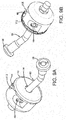
- FIG. 3 A first embodiment of the control valve 100 is shown in Figures 3-10 .
- the control valve 100 has a removable cap 110 that has detents 112 on the outer rim surface that snap onto aligned edges 114 of a valve body 120.
- the cap has a central hole 116 for receiving a distal end 84 of the tire valve stem 80.
- a filter 118 Positioned underneath the cap 110 is a filter 118 for filtering the inlet ambient air that enters the control valve 100 from inlet passageways 119 located between the valve body rim and the cap outer rim.
- the valve body 120 is preferably round and compact, and has a central bore 130 for receiving a main pressure module 132.
- the main pressure module 132 has a first end 133 housing an internal main pressure chamber 134, and a second end 136 having an optional valve core 138 positioned therein, preferably a Schrader valve core.
- the second end 136 is useful for connection to an external pressure source so that the system may be manually filled by a user.
- Figure 9c illustrates the distal end 84 of the valve stem 80 positioned in the main pressure chamber 134.
- the main pressure module 132 has sealing gaskets 135, 137 to maintain a fluid tight seal.
- Auxiliary pressurized air from an external pump source may be connected to the distal end 136 to manually inflate the tire cavity 28 through the valve stem 80 to the desired pressure.
- the valve body 120 has a plurality of chambers 142, 144, 145, 146, 147, 148 that are preferably concentrically located about the main pressure chamber 134. Chambers 142, 145 and 148 remain empty and are optional fluid reservoirs. Chambers 144, 146 preferably each have a check valve module 150, 152 inserted therein. Each check valve module 150, 152 has a central passageway 154, 156 in fluid communication with an inlet end 150a, 152a and an outlet end 150b, 152b. Preferably, each passageway 154, 156 are parallel to each other and are straight with no bends. Positioned within each central passageway 154, 156 is at least one check valve 155, 159.
- check valves 155, 157, and 158, 159 mounted in series in a respective module.
- the four check valves are all oriented in the same direction, so that the flow travels from the inlet to the outlet without reversing.
- the check valves 155, 157, 158, 159 are preferably duck bill type check valves and are oriented to allow flow from the inlet end to the outlet end, and to prevent backflow in the direction from the outlet to the inlet.
- Each check valve module 150, 152 has first and second seals 164, 166.
- One of the check valve modules functions as a pump inlet chamber, while the other chamber functions as a pump outlet chamber. If the valve is connected to a peristaltic pump, the direction of the tire rotation determines which check valve module functions as a pump inlet chamber and pump outlet chamber.
- Located between the first and second seals 164, 166 is an outlet port 168, 170 that is in fluid communication with a respective passageway 154, 156.
- Each outlet port 168, 170 is preferably located between the first and second set of check valves as shown in Figure 7 .
- Outlet port 168 is in fluid communication with port 46, while outlet port 170 is in fluid communication with port 44.
- Each outlet end 150b, 152b of each check valve module 150, 152 is connected in fluid communication with angled passageways 160, 162 respectively.
- the angled passageways 160, 162 are in fluid communication with the main pressure chamber 134.
- the main pressure chamber 134 is in fluid communication with the inlet end of a relief valve 180, the inlet end of the tire valve stem 80, and the outlet ends 159b, 152b of each check valve module.
- the relief valve 180 is positioned in chamber 147 of control valve 100.
- the relief valve is designed to prevent over inflation of the tire cavity.
- the inlet 184 to the relief valve 180 is in fluid communication with the main pressure chamber 134 via conduit 182.
- the outlet 186 to the relief valve 180 is in fluid communication with the ambient atmosphere.
- the relief valve has a spring 188 that biases the valve core 190 in the closed position. When the inlet pressure to the relief valve exceeds the desired set pressure exerted on the plunger 190, the valve seat 192 unseats allowing the pressurized air to vent through the relief valve body and out through the exit holes 186.
- the outlet pressurized air from the pumping tube is controlled by the spring regulated relief valve 180. If the tire cavity pressure is less than the set pressure, the tire valve 82 opens, allowing air into the tire cavity. If the tire cavity pressure is higher than the set pressure, the pumped air will release through the relief valve into the atmosphere.
- the set pressure is determined by selecting a spring of the relief valve that actuates at the desired set pressure.
- the spring of the tire valve stem 82 is selected to have a lower cracking pressure so that the when the main chamber pressure is below the relief valve set pressure and the pressure difference between the pressurized air and tire cavity is higher than the cracking pressure, the tire cavity will be pumped with pressurized air until the relief valve set pressure is reached.
- An adjustable relief valve may be substituted for the fixed relief valve 180 shown herein.
- the adjustable relief valve has a screw adjustment that allows the set pressure to be easily adjusted.
- FIGS 11A-11C The operation of the system is shown in Figures 11A-11C .
- outside ambient air is sucked into the system through the inlet passageways 119 located at the interface of the outer cap rim and the valve body 120.
- the ambient air passes through the filter 118 and then through check valve 155 of the first check valve module 150.
- the air exits the check valve module 150 through port 170, through valve body port 44 and then into the inlet of the peristaltic pump 15a.
- the air is compressed in the peristaltic pump and exits the pump chamber to pump outlet 15b.
- the compressed air enters the control valve through port 46.
- the compressed air travels through the second check valve module 152 through port 168.
- the control valve can operate bi-directionally, so that if the tire rotates in the opposite direction, the system will pump without any changes being made to the system.
- the bi-directionality in pumping air from the pump is made possible by the dual air flow paths 154,156, wherein each flow path preferably is straight with no bends.
- the bi-directional feature is useful when the pump is located in the tire, so that if the tire rotates in either direction the system will inflate the tire cavity.
- the bi-directional feature is optional.
- the system may also work for a one directional system, a check valve from each check valve module i.e., check valves 157 and 158 can be eliminated.
- control valve retains the ability to manually fill air into the tire with the use of a standard external pump, while the control valve directs the pressurized air to pump the tire cavity during operation of the system.
- the control valve has a compact housing that can be installed onto a tire valve stem for pumping air from the pump into the tire cavity through the valve stem.
- the control valve prevents the tire cavity from being over pressurized with either the manual fill or via the peristaltic pump.
- the set pressure is easily adjusted by screw adjustment to the control regulator 68 without dismounting the tire.
- the filter and the control valve in its entirety may be easily replaced if needed.
Landscapes
- Engineering & Computer Science (AREA)
- Mechanical Engineering (AREA)
- General Engineering & Computer Science (AREA)
- Check Valves (AREA)
- Tires In General (AREA)
- Safety Valves (AREA)
- Valve Housings (AREA)
Abstract
Description
- The invention relates generally to valves for tires, and more particularly to a control valve for an air maintenance tire.
- Normal air diffusion reduces tire pressure over time. The natural state of tires is under inflated. Accordingly, drivers must repeatedly act to maintain tire pressures or they will see reduced fuel economy, tire life and reduced vehicle braking and handling performance. Tire Pressure Monitoring Systems have been proposed to warn drivers when tire pressure is significantly low. Such systems, however, remain dependent upon the driver taking remedial action when warned to re-inflate a tire to recommended pressure. It is a desirable, therefore, to incorporate an air maintenance feature within a tire that will self-maintain the tire air pressure in order to compensate for any reduction in tire pressure over time without a need for driver intervention.
- The invention relates to a control valve in accordance with
claim 1, 9 or 10 respectively, and to an air maintenance tire in accordance withclaim 12. - Dependent claims refer to preferred embodiments of the invention.
- One or more preferred embodiments of the present invention provide a control valve for controlling the pressure of a tire cavity during operation of a pump having a pump inlet and a pump outlet, said tire having a tire cavity and a valve stem having a distal end, the control valve comprising a valve body having a pump inlet chamber, a pump outlet chamber, and a control chamber, wherein a first check valve is positioned in the pump inlet chamber so that the first check valve is located between an air inlet and a pump inlet port, said valve body further comprising a second check valve positioned in the pump outlet chamber, said second check valve being positioned between a pump outlet port and a main pressure chamber, said valve body further comprising a relief valve positioned in the control chamber, said relief valve having an inlet end in fluid communication with a main pressure chamber and an outlet end in fluid communication with the atmosphere, and wherein the main pressure chamber is in fluid communication with the pump outlet chamber, and the distal end of the tire valve stem.
- One or more preferred embodiments of the present invention provide a control valve for controlling the pressure of a tire cavity during operation of a pump having a pump inlet and a pump outlet, said tire having a tire cavity and a valve stem having a distal end, the control valve comprising a valve body having a pump inlet chamber, a pump outlet chamber, and a control chamber, wherein a first check valve is positioned in the pump inlet chamber so that the first check valve is located between an air inlet and a pump inlet port, said valve body further comprising a second check valve positioned in the pump outlet chamber, said second check valve being positioned between a pump outlet port and a main pressure chamber, said valve body further comprising a relief valve positioned in the control chamber, said relief valve having an inlet end in fluid communication with a main pressure chamber and an outlet end in fluid communication with the atmosphere, wherein the main pressure chamber is in fluid communication with the pump outlet chamber, and the distal end of the tire valve stem, and wherein the pump inlet port and pump outlet port are connectable to the pump inlet, pump outlet, respectively.
- One or more preferred embodiments of the present invention provide a control valve for controlling the pressure of a tire cavity during operation of a pump having a pump inlet and a pump outlet, said tire having a tire cavity and a valve stem having a distal end, the control valve comprising a valve body having a pump inlet chamber, a pump outlet chamber, and a control chamber, wherein a first check valve is positioned in the pump inlet chamber so that the first check valve is located between an air inlet and a pump inlet port, said valve body further comprising a second check valve positioned in the pump outlet chamber, said second check valve being positioned between a pump outlet port and a main pressure chamber, said valve body further comprising a relief valve positioned in the control chamber, said relief valve having an inlet end in fluid communication with a main pressure chamber and an outlet end in fluid communication with the atmosphere, wherein the main pressure chamber is in fluid communication with the pump outlet chamber, and the distal end of the tire valve stem, and wherein the valve body is shaped like a cup.
- One or more preferred embodiments of the present invention provide a control valve for controlling the pressure of a tire cavity during operation of a pump having a pump inlet and a pump outlet, said tire having a tire cavity and a valve stem having a distal end, the control valve comprising a valve body having a pump inlet chamber, a pump outlet chamber, and a control chamber, wherein a first check valve is positioned in the pump inlet chamber so that the first check valve is located between an air inlet and a pump inlet port, said valve body further comprising a second check valve positioned in the pump outlet chamber, said second check valve being positioned between a pump outlet port and a main pressure chamber, said valve body further comprising a relief valve positioned in the control chamber, said relief valve having an inlet end in fluid communication with a main pressure chamber and an outlet end in fluid communication with the atmosphere, wherein the main pressure chamber is in fluid communication with the pump outlet chamber, and the distal end of the tire valve stem, and wherein a cap is received over a first end of the valve body.
- One or more preferred embodiments of the present invention provide a control valve for controlling the pressure of a tire cavity during operation of a pump having a pump inlet and a pump outlet, said tire having a tire cavity and a valve stem having a distal end, the control valve comprising a valve body having a pump inlet chamber, a pump outlet chamber, and a control chamber, wherein a first check valve is positioned in the pump inlet chamber so that the first check valve is located between an air inlet and a pump inlet port, said valve body further comprising a second check valve positioned in the pump outlet chamber, said second check valve being positioned between a pump outlet port and a main pressure chamber, said valve body further comprising a relief valve positioned in the control chamber, said relief valve having an inlet end in fluid communication with a main pressure chamber and an outlet end in fluid communication with the atmosphere, wherein the main pressure chamber is in fluid communication with the pump outlet chamber, and the distal end of the tire valve stem, and wherein the valve body further comprises a cap having detents which latch with an outer rim of the valve body forming a snap fit.
- One or more preferred embodiments of the present invention provide a control valve for controlling the pressure of a tire cavity during operation of a pump having a pump inlet and a pump outlet, said tire having a tire cavity and a valve stem having a distal end, the control valve comprising a valve body having a pump inlet chamber, a pump outlet chamber, and a control chamber, wherein a first check valve is positioned in the pump inlet chamber so that the first check valve is located between an air inlet and a pump inlet port, said valve body further comprising a second check valve positioned in the pump outlet chamber, said second check valve being positioned between a pump outlet port and a main pressure chamber, said valve body further comprising a relief valve positioned in the control chamber, said relief valve having an inlet end in fluid communication with a main pressure chamber and an outlet end in fluid communication with the atmosphere, wherein the main pressure chamber is in fluid communication with the pump outlet chamber, and the distal end of the tire valve stem, and wherein the valve body is injection molded.
- One or more preferred embodiments of the present invention provide a control valve for controlling the pressure of a tire cavity during operation of a pump having a pump inlet and a pump outlet, said tire having a tire cavity and a valve stem having a distal end, the control valve comprising a valve body having a pump inlet chamber, a pump outlet chamber, and a control chamber, wherein a first check valve is positioned in the pump inlet chamber so that the first check valve is located between an air inlet and a pump inlet port, said valve body further comprising a second check valve positioned in the pump outlet chamber, said second check valve being positioned between a pump outlet port and a main pressure chamber, said valve body further comprising a relief valve positioned in the control chamber, said relief valve having an inlet end in fluid communication with a main pressure chamber and an outlet end in fluid communication with the atmosphere, wherein the main pressure chamber is in fluid communication with the pump outlet chamber, and the distal end of the tire valve stem, and wherein the pump inlet chamber has a third check valve positioned between the pump inlet port and the main pressure chamber.
- One or more preferred embodiments of the present invention provide a control valve for controlling the pressure of a tire cavity during operation of a pump having a pump inlet and a pump outlet, said tire having a tire cavity and a valve stem having a distal end, the control valve comprising a valve body having a pump inlet chamber, a pump outlet chamber, and a control chamber, wherein a first check valve is positioned in the pump inlet chamber so that the first check valve is located between an air inlet and a pump inlet port, said valve body further comprising a second check valve positioned in the pump outlet chamber, said second check valve being positioned between a pump outlet port and a main pressure chamber, said valve body further comprising a relief valve positioned in the control chamber, said relief valve having an inlet end in fluid communication with a main pressure chamber and an outlet end in fluid communication with the atmosphere, wherein the main pressure chamber is in fluid communication with the pump outlet chamber, and the distal end of the tire valve stem, and wherein the pump outlet chamber has a fourth check valve positioned between the pump outlet port and an inlet hole.
- One or more preferred embodiments of the present invention provide a control valve for controlling the pressure of a tire cavity during operation of a pump having a pump inlet and a pump outlet, said tire having a tire cavity and a valve stem having a distal end, the control valve comprising a valve body having a pump inlet chamber, a pump outlet chamber, and a control chamber, wherein a first check valve is positioned in the pump inlet chamber so that the first check valve is located between an air inlet and a pump inlet port, said valve body further comprising a second check valve positioned in the pump outlet chamber, said second check valve being positioned between a pump outlet port and a main pressure chamber, said valve body further comprising a relief valve positioned in the control chamber, said relief valve having an inlet end in fluid communication with a main pressure chamber and an outlet end in fluid communication with the atmosphere, wherein the main pressure chamber is in fluid communication with the pump outlet chamber, and the distal end of the tire valve stem, and wherein the main pressure chamber is in fluid communication with a manual fill assembly disposed at an outer end of the valve body.
- One or more preferred embodiments of the present invention provide a control valve for controlling the pressure of a tire cavity during operation of a pump having a pump inlet and a pump outlet, said tire having a tire cavity and a valve stem having a distal end, the control valve comprising a valve body having a pump inlet chamber, a pump outlet chamber, and a control chamber, wherein a first check valve is positioned in the pump inlet chamber so that the first check valve is located between an air inlet and a pump inlet port, said valve body further comprising a second check valve positioned in the pump outlet chamber, said second check valve being positioned between a pump outlet port and a main pressure chamber, said valve body further comprising a relief valve positioned in the control chamber, said relief valve having an inlet end in fluid communication with a main pressure chamber and an outlet end in fluid communication with the atmosphere, wherein the main pressure chamber is in fluid communication with the pump outlet chamber, and the distal end of the tire valve stem, and having an internal passageway in fluid communication with the main pressure chamber, wherein the internal passageway is configured for mounted on the distal end of the tire valve stem.
- One or more preferred embodiments of the present invention provide a control valve for controlling the pressure of a tire cavity during operation of a pump having a pump inlet and a pump outlet, said tire having a tire cavity and a valve stem having a distal end, the control valve comprising a valve body having a pump inlet chamber, a pump outlet chamber, and a control chamber, wherein a first check valve module is positioned in the pump inlet chamber, said first check valve module having a first flow path and a first check valve mounted therein, said valve body further comprising a second check valve module positioned in the pump outlet chamber, said second check valve module having a second flow path and a second check valve mounted therein, said valve body further comprising a relief valve positioned in the control chamber, said relief valve having an inlet end in fluid communication with a main pressure chamber and an outlet end in fluid communication with the atmosphere, and wherein the main pressure chamber is in fluid communication with the pump inlet chamber and the pump outlet chamber, and the distal end of the tire valve stem.
- One or more preferred embodiments of the present invention provide a control valve for controlling the pressure of a tire cavity during operation of a pump, said tire having a tire cavity and a valve stem having a distal end, the control valve comprising a valve body having a pump inlet port, a pump outlet port, and a main pressure chamber, wherein a first check valve is positioned between an air inlet hole and the pump inlet port, wherein a second check valve is positioned between a pump outlet port and a main pressure chamber, said valve body further comprising a relief valve having an inlet end in fluid communication with a main pressure chamber and an outlet end in fluid communication with the atmosphere, wherein the main pressure chamber is in fluid communication with the pump inlet port, the pump outlet port, and the tire valve stem, and whereby compressed air from the pump outlet is communicated to the main pressure chamber of the valve device, and if the pressure of the compressed air exceeds the cracking pressure of the tire valve stem, the tire cavity is inflated until the pressure of the main pressure chamber exceeds the set pressure of the relief valve.
- One or more preferred embodiments of the present invention provide a control valve for controlling the pressure of a tire cavity during operation of a pump, said tire having a tire cavity and a valve stem having a distal end, the control valve comprising a valve body having a pump inlet port, a pump outlet port, and a main pressure chamber, wherein a first check valve is positioned between an air inlet hole and the pump inlet port, wherein a second check valve is positioned between a pump outlet port and a main pressure chamber, said valve body further comprising a relief valve having an inlet end in fluid communication with a main pressure chamber and an outlet end in fluid communication with the atmosphere, wherein the main pressure chamber is in fluid communication with the pump inlet port, the pump outlet port, and the tire valve stem, and whereby compressed air from the pump outlet is communicated to the main pressure chamber of the valve device, and if the pressure of the compressed air exceeds the cracking pressure of the tire valve stem, the tire cavity is inflated until the pressure of the main pressure chamber exceeds the set pressure of the relief valve, and wherein the valve body has an inlet hole for mounting to the distal end of the tire valve stem so that fluid from the main pressure chamber is communicable to the tire valve stem.
- One or more preferred embodiments of the present invention provide an air maintenance tire assembly comprising a tire having a tire cavity, said tire having a valve stem projecting outward from the tire cavity, said valve stem having an internal valve stem air passageway in communication with the tire cavity operative to direct pressurized air from the valve stem air passageway into the cavity, a pump tube having an inlet end and an outlet end and being configured for pumping pressurized air into the tire cavity, the control valve comprising a valve body having a pump inlet port, a pump outlet port, and a main pressure chamber, wherein a first check valve is positioned between an air inlet hole and the pump inlet port, and a second check valve is positioned between a pump outlet port and the main pressure chamber, said valve body further comprising a relief valve having an inlet end in fluid communication with a main pressure chamber and an outlet end in fluid communication with the atmosphere, wherein the main pressure chamber is in fluid communication with the pump inlet port, the pump outlet port, and the tire valve stem, and wherein compressed air from the pump outlet is communicated to the main pressure chamber of the valve device, and if the pressure of the compressed air exceeds the cracking pressure of the tire valve stem, the tire cavity is inflated until the pressure of the main pressure chamber exceeds the set pressure of the relief valve.
- One or more preferred embodiments of the present invention provide an air maintenance tire assembly comprising a tire having a tire cavity, said tire having a valve stem projecting outward from the tire cavity, said valve stem having an internal valve stem air passageway in communication with the tire cavity operative to direct pressurized air from the valve stem air passageway into the cavity, a pump tube having an inlet end and an outlet end and being configured for pumping pressurized air into the tire cavity, the control valve comprising a valve body having a pump inlet port, a pump outlet port, and a main pressure chamber, wherein a first check valve is positioned between an air inlet hole and the pump inlet port, and a second check valve is positioned between a pump outlet port and the main pressure chamber, said valve body further comprising a relief valve having an inlet end in fluid communication with a main pressure chamber and an outlet end in fluid communication with the atmosphere, wherein the main pressure chamber is in fluid communication with the pump inlet port, the pump outlet port, and the tire valve stem, wherein compressed air from the pump outlet is communicated to the main pressure chamber of the valve device, and if the pressure of the compressed air exceeds the cracking pressure of the tire valve stem, the tire cavity is inflated until the pressure of the main pressure chamber exceeds the set pressure of the relief valve, and wherein the pump inlet chamber has a third check valve positioned between the pump inlet port and the main pressure chamber.
- One or more preferred embodiments of the present invention provide an air maintenance tire assembly comprising a tire having a tire cavity, said tire having a valve stem projecting outward from the tire cavity, said valve stem having an internal valve stem air passageway in communication with the tire cavity operative to direct pressurized air from the valve stem air passageway into the cavity, a pump tube having an inlet end and an outlet end and being configured for pumping pressurized air into the tire cavity, the control valve comprising a valve body having a pump inlet port, a pump outlet port, and a main pressure chamber, wherein a first check valve is positioned between an air inlet hole and the pump inlet port, and a second check valve is positioned between a pump outlet port and the main pressure chamber, said valve body further comprising a relief valve having an inlet end in fluid communication with a main pressure chamber and an outlet end in fluid communication with the atmosphere, wherein the main pressure chamber is in fluid communication with the pump inlet port, the pump outlet port, and the tire valve stem, wherein compressed air from the pump outlet is communicated to the main pressure chamber of the valve device, and if the pressure of the compressed air exceeds the cracking pressure of the tire valve stem, the tire cavity is inflated until the pressure of the main pressure chamber exceeds the set pressure of the relief valve, and wherein the pump outlet chamber has a fourth check valve positioned between the pump outlet port and an inlet hole.
- One or more preferred embodiments of the present invention provide an air maintenance tire assembly comprising a tire having a tire cavity, said tire having a valve stem projecting outward from the tire cavity, said valve stem having an internal valve stem air passageway in communication with the tire cavity operative to direct pressurized air from the valve stem air passageway into the cavity, a pump tube having an inlet end and an outlet end and being configured for pumping pressurized air into the tire cavity, the control valve comprising a valve body having a pump inlet port, a pump outlet port, and a main pressure chamber, wherein a first check valve is positioned between an air inlet hole and the pump inlet port, and a second check valve is positioned between a pump outlet port and the main pressure chamber, said valve body further comprising a relief valve having an inlet end in fluid communication with a main pressure chamber and an outlet end in fluid communication with the atmosphere, wherein the main pressure chamber is in fluid communication with the pump inlet port, the pump outlet port, and the tire valve stem, wherein compressed air from the pump outlet is communicated to the main pressure chamber of the valve device, and if the pressure of the compressed air exceeds the cracking pressure of the tire valve stem, the tire cavity is inflated until the pressure of the main pressure chamber exceeds the set pressure of the relief valve, and wherein the assembly is bidirectional.
- One or more preferred embodiments of the present invention provide an air maintenance tire assembly comprising a tire having a tire cavity, said tire having a valve stem projecting outward from the tire cavity, said valve stem having an internal valve stem air passageway in communication with the tire cavity operative to direct pressurized air from the valve stem air passageway into the cavity, a pump tube having an inlet end and an outlet end and being configured for pumping pressurized air into the tire cavity, the control valve comprising a valve body having a pump inlet port, a pump outlet port, and a main pressure chamber, wherein a first check valve is positioned between an air inlet hole and the pump inlet port, and a second check valve is positioned between a pump outlet port and the main pressure chamber, said valve body further comprising a relief valve having an inlet end in fluid communication with a main pressure chamber and an outlet end in fluid communication with the atmosphere, wherein the main pressure chamber is in fluid communication with the pump inlet port, the pump outlet port, and the tire valve stem, wherein compressed air from the pump outlet is communicated to the main pressure chamber of the valve device, and if the pressure of the compressed air exceeds the cracking pressure of the tire valve stem, the tire cavity is inflated until the pressure of the main pressure chamber exceeds the set pressure of the relief valve, and wherein the relief valve is operable to vent pressurized air when an air pressure within the tire cavity is at or above a predetermined optimal inflation level, and the relief valve is operable to close when air pressure within the tire cavity is below the predetermined optimal inflation level.
- One or more preferred embodiments of the present invention provide an air maintenance tire assembly comprising a tire having a tire cavity, said tire having a valve stem projecting outward from the tire cavity, said valve stem having an internal valve stem air passageway in communication with the tire cavity operative to direct pressurized air from the valve stem air passageway into the cavity, a pump tube having an inlet end and an outlet end and being configured for pumping pressurized air into the tire cavity, a control valve having a valve body having a pump inlet chamber, a pump outlet chamber, and a control chamber, wherein a first check valve is positioned in the pump inlet chamber so that the first check valve is located between an air inlet and a pump inlet port, said valve body further comprising a second check valve positioned in the pump outlet chamber, said second check valve being positioned between a pump outlet port and a main pressure chamber, said valve body further comprising a relief valve positioned in the control chamber, said relief valve having an inlet end in fluid communication with a main pressure chamber and an outlet end in fluid communication with the atmosphere, and wherein the main pressure chamber is in fluid communication with the pump inlet chamber and the pump outlet chamber, and the distal end of the tire valve stem.
- One or more preferred embodiments of the present invention provide an air maintenance tire assembly comprising a tire having a tire cavity, said tire having a valve stem projecting outward from the tire cavity, said valve stem having an internal valve stem air passageway in communication with the tire cavity operative to direct pressurized air from the valve stem air passageway into the cavity, a pump tube having an inlet end and an outlet end and being configured for pumping pressurized air into the tire cavity, a control valve having a valve body having a pump inlet chamber, a pump outlet chamber, and a control chamber, wherein a first check valve is positioned in the pump inlet chamber so that the first check valve is located between an air inlet and a pump inlet port, said valve body further comprising a second check valve positioned in the pump outlet chamber, said second check valve being positioned between a pump outlet port and a main pressure chamber, said valve body further comprising a relief valve positioned in the control chamber, said relief valve having an inlet end in fluid communication with a main pressure chamber and an outlet end in fluid communication with the atmosphere, wherein the main pressure chamber is in fluid communication with the pump inlet chamber and the pump outlet chamber, and the distal end of the tire valve stem, and wherein the pump inlet chamber has a third check valve positioned between the pump inlet port and the main pressure chamber.
- One or more preferred embodiments of the present invention provide an air maintenance tire assembly comprising a tire having a tire cavity, said tire having a valve stem projecting outward from the tire cavity, said valve stem having an internal valve stem air passageway in communication with the tire cavity operative to direct pressurized air from the valve stem air passageway into the cavity, a pump tube having an inlet end and an outlet end and being configured for pumping pressurized air into the tire cavity, a control valve having a valve body having a pump inlet chamber, a pump outlet chamber, and a control chamber, wherein a first check valve is positioned in the pump inlet chamber so that the first check valve is located between an air inlet and a pump inlet port, said valve body further comprising a second check valve positioned in the pump outlet chamber, said second check valve being positioned between a pump outlet port and a main pressure chamber, said valve body further comprising a relief valve positioned in the control chamber, said relief valve having an inlet end in fluid communication with a main pressure chamber and an outlet end in fluid communication with the atmosphere, wherein the main pressure chamber is in fluid communication with the pump inlet chamber and the pump outlet chamber, and the distal end of the tire valve stem, and wherein the pump outlet chamber has a fourth check valve positioned between the pump outlet port and an inlet hole.
- One or more preferred embodiments of the present invention provide an air maintenance tire assembly comprising a tire having a tire cavity, said tire having a valve stem projecting outward from the tire cavity, said valve stem having an internal valve stem air passageway in communication with the tire cavity operative to direct pressurized air from the valve stem air passageway into the cavity, a pump tube having an inlet end and an outlet end and being configured for pumping pressurized air into the tire cavity, a control valve having a valve body having a pump inlet chamber, a pump outlet chamber, and a control chamber, wherein a first check valve is positioned in the pump inlet chamber so that the first check valve is located between an air inlet and a pump inlet port, said valve body further comprising a second check valve positioned in the pump outlet chamber, said second check valve being positioned between a pump outlet port and a main pressure chamber, said valve body further comprising a relief valve positioned in the control chamber, said relief valve having an inlet end in fluid communication with a main pressure chamber and an outlet end in fluid communication with the atmosphere, wherein the main pressure chamber is in fluid communication with the pump inlet chamber and the pump outlet chamber, and the distal end of the tire valve stem, and wherein the main pressure chamber is in fluid communication with a manual fill assembly disposed at an outer end of the valve body.
- One or more preferred embodiments of the present invention provide an air maintenance tire assembly comprising a tire having a tire cavity, said tire having a valve stem projecting outward from the tire cavity, said valve stem having an internal valve stem air passageway in communication with the tire cavity operative to direct pressurized air from the valve stem air passageway into the cavity, a pump tube having an inlet end and an outlet end and being configured for pumping pressurized air into the tire cavity, a control valve having a valve body having a pump inlet chamber, a pump outlet chamber, and a control chamber, wherein a first check valve is positioned in the pump inlet chamber so that the first check valve is located between an air inlet and a pump inlet port, said valve body further comprising a second check valve positioned in the pump outlet chamber, said second check valve being positioned between a pump outlet port and a main pressure chamber, said valve body further comprising a relief valve positioned in the control chamber, said relief valve having an inlet end in fluid communication with a main pressure chamber and an outlet end in fluid communication with the atmosphere, wherein the main pressure chamber is in fluid communication with the pump inlet chamber and the pump outlet chamber, and the distal end of the tire valve stem, and wherein the valve body has an internal passageway in fluid communication with the main pressure chamber, wherein the internal passageway is configured for mounted on the distal end of the tire valve stem.
- According to a preferred aspect of the invention, a control valve assembly mounts to a tire valve stem and operably controls a flow of pressurized air through the tire valve stem from either an external pressurized air source or a wheel or tire mounted pressurized air source. The tire mounted pressurized air source may be a peristaltic pump preferably built into the tire sidewall. The wheel mounted pressurized air source may comprise a wheel mounted pump. The control valve assembly optionally includes a bi-directional feature so that if a peristaltic pump is used, the tire may rotate in either direction and pump air into the valve stem.
- "Axial" and "axially" means lines or directions that are parallel to the axis of rotation of the tire.
- "Circumferential" means lines or directions extending along the perimeter of the surface of the annular tread perpendicular to the axial direction.
- "Duck Valve" is a check valve manufactured from rubber or synthetic elastomer, and shaped like the beak of a duck. One end of the valve is stretched over the outlet of a supply line, conforming itself to the shape of the line. The other end, the duckbill, retains its natural flattened shape. When pressurized air is pumped from the supply line through the duckbill, the flattened end opens to permit the pressurized air to pass. When pressure is removed, the duckbill end returns to its flattened shape, preventing backflow.
- "Equatorial Centerplane (CP)" means the plane perpendicular to the tire's axis of rotation and passing through the center of the tread.
- "Footprint" means the contact patch or area of contact of the tire tread with a flat surface at zero speed and under normal load and pressure.
- "Lateral" means an axial direction.
- "Peristaltic" means operating by means of wave-like contractions that propel contained matter, such as air, along tubular pathways.
- "Radial" and "radially" means directions radially toward or away from the axis of rotation of the tire.
- The invention will be described by way of example and with reference to the accompanying drawings in which:
-
FIG.1A is a perspective view of a tire with a control valve of the present invention mounted on a tire valve stem. -
FIG.1B is a close up view of the control valve ofFig. 1A . -
FIG. 2 is a partial view of the tire shown with the control valve connected to a pump mounted in the tire (and shown in phantom). -
FIG. 3 is a perspective rear view of the control valve of the present invention. -
FIG. 4 is a perspective rear view of the control valve of the present invention shown with the component parts. -
FIG. 5 is an exploded view of the control valve of the present invention. -
FIG. 6 is a front view of the housing of the control valve with the check valve modules mounted therein. -
FIG. 7 is a cross-sectional view ofFIG. 6 in the direction 7-7. -
FIG. 8 is a cross-sectional view ofFIG. 6 in the direction 8-8. -
FIG. 9A is a perspective front view of the control valve mounted on a tire valve (tire omitted for clarity); -
FIG. 9B is a perspective rear view of the control valve mounted on a tire valve (tire omitted for clarity). -
FIG. 9C is a cross-sectional side view of the control valve mounted to a tire valve (tire omitted for clarity). -
FIG. 9D is a cross-sectional view of the manual fill assembly and main pressure chamber. -
FIG. 10A is a front view of the control valve mounted to a tire valve showing the air inlet ports. -
FIG. 10B is a close up view of the cover and housing interface showing the air inlet ports. -
FIG. 11A is a side cross-sectional view of the control valve showing the air pathway from the inlet to the pump inlet. -
FIGS. 11B and 11C are side cross-sectional views of the control valve showing the air pathway from the pump outlet through the control valve and into the tire. - Referring to
FIG 1 , acontrol valve assembly 100 of the present invention is shown mounted to avalve stem 80 of atire 10. Thetire 10 is mounted on atire rim body 12. The tire may include an internalperistaltic pump 15 which may be mounted in the tire sidewall. Theperistaltic pump 15 may preferably be annular or 360-degree pump so that the inlet end of the pump is several inches from the outlet end of the pump assembly. The tire and rim body enclose atire cavity 28. The tire includes a conventional valve stem 80 for pumping air into thetire cavity 28. Theconventional valve stem 80 has adistal end 84 having aninternal valve core 82 such as a Presta valve core or a Schrader valve core. The tire valve stem has asecond end 86 that is positioned in the tire cavity so that fluid may be communicated from thedistal end 84 of the valve stem through thetire valve core 84 and into the cavity. - The
peristaltic pump 15 may comprise a molded annular passageway or an annular air tube that is inserted into an annular passageway. The tube is formed of a resilient, flexible material such as plastic or rubber compounds that are capable of withstanding repeated deformation cycles. So, constructed, the tube may deform within a tire into a flattened condition subject to external force and, upon removal of such force, return to an original sectional configuration. In the embodiment shown, the cross-section of the tube in an unstressed state is generally circular but other alternative tube geometries may be employed if desired. The tube is of a diameter sufficient to operatively pass a requisite volume of air sufficient for the purpose of pumping air into thetire cavity 28 to maintain thetire 10 at a preferred inflation pressure. - The peristaltic principles of incorporating a deformable air tube within a tire are shown and described in
US-B-8,113,254 . In the patented system, the tube is incorporated within an annular tire passageway formed within the tire proximate a tire bead region. As the tire rotates air from outside the tire is admitted into the tube and pumped along the air tube by the progressive squeezing of the tube within the tire as the tire rotates. Air is thus forced into an outlet valve and therefrom into the tire cavity to maintain air pressure within the tire cavity at a desired pressure level. - As partially shown in
Figure 2 , thepump 15 is preferably annular and is preferably located in thetire sidewall 18 region proximate to abead region 22. However, other configurations for the air tube may be devised without departing from the invention. Opposite ends 15a, 15b of the pump connect into aninline connector block 34.Conduits first end connector block 34, wherein each first end is connected to a respective end of thepumping tube conduit control valve ports Conduits pump 15. In the pumping mode, forward revolution of the tire, one conduit delivers air to the pumping tube and the other conduit conducts air pressurized by the pumping tube to thebi-directional block 40. In the reverse rotational direction of the tire, theconduits - A first embodiment of the
control valve 100 is shown inFigures 3-10 . As shown inFigure 3 , thecontrol valve 100 has aremovable cap 110 that hasdetents 112 on the outer rim surface that snap onto alignededges 114 of avalve body 120. The cap has acentral hole 116 for receiving adistal end 84 of thetire valve stem 80. Positioned underneath thecap 110 is afilter 118 for filtering the inlet ambient air that enters thecontrol valve 100 frominlet passageways 119 located between the valve body rim and the cap outer rim. - The
valve body 120 is preferably round and compact, and has acentral bore 130 for receiving amain pressure module 132. As shown inFigure 9D , themain pressure module 132 has afirst end 133 housing an internalmain pressure chamber 134, and asecond end 136 having anoptional valve core 138 positioned therein, preferably a Schrader valve core. Thesecond end 136 is useful for connection to an external pressure source so that the system may be manually filled by a user.Figure 9c illustrates thedistal end 84 of thevalve stem 80 positioned in themain pressure chamber 134. Themain pressure module 132 has sealinggaskets distal end 136 to manually inflate thetire cavity 28 through thevalve stem 80 to the desired pressure. - The
valve body 120 has a plurality ofchambers main pressure chamber 134.Chambers Chambers check valve module check valve module central passageway inlet end outlet end passageway central passageway check valve check valves check valves - Each
check valve module second seals second seals outlet port respective passageway outlet port Figure 7 .Outlet port 168 is in fluid communication withport 46, whileoutlet port 170 is in fluid communication withport 44. - Each
outlet end check valve module angled passageways angled passageways main pressure chamber 134. Themain pressure chamber 134 is in fluid communication with the inlet end of arelief valve 180, the inlet end of thetire valve stem 80, and the outlet ends 159b, 152b of each check valve module. - The
relief valve 180 is positioned inchamber 147 ofcontrol valve 100. The relief valve is designed to prevent over inflation of the tire cavity. Theinlet 184 to therelief valve 180 is in fluid communication with themain pressure chamber 134 viaconduit 182. Theoutlet 186 to therelief valve 180 is in fluid communication with the ambient atmosphere. The relief valve has aspring 188 that biases thevalve core 190 in the closed position. When the inlet pressure to the relief valve exceeds the desired set pressure exerted on theplunger 190, the valve seat 192 unseats allowing the pressurized air to vent through the relief valve body and out through the exit holes 186. - In this embodiment, the outlet pressurized air from the pumping tube is controlled by the spring
regulated relief valve 180. If the tire cavity pressure is less than the set pressure, thetire valve 82 opens, allowing air into the tire cavity. If the tire cavity pressure is higher than the set pressure, the pumped air will release through the relief valve into the atmosphere. The set pressure is determined by selecting a spring of the relief valve that actuates at the desired set pressure. The spring of the tire valve stem 82 is selected to have a lower cracking pressure so that the when the main chamber pressure is below the relief valve set pressure and the pressure difference between the pressurized air and tire cavity is higher than the cracking pressure, the tire cavity will be pumped with pressurized air until the relief valve set pressure is reached. - An adjustable relief valve may be substituted for the fixed
relief valve 180 shown herein. The adjustable relief valve has a screw adjustment that allows the set pressure to be easily adjusted. - The operation of the system is shown in
Figures 11A-11C . As shown inFigures 10A &10B, outside ambient air is sucked into the system through the inlet passageways 119 located at the interface of the outer cap rim and thevalve body 120. The ambient air passes through thefilter 118 and then throughcheck valve 155 of the firstcheck valve module 150. The air exits thecheck valve module 150 throughport 170, throughvalve body port 44 and then into the inlet of theperistaltic pump 15a. As the tire rotates, the air is compressed in the peristaltic pump and exits the pump chamber to pumpoutlet 15b. The compressed air enters the control valve throughport 46. As shown inFigure 11b , the compressed air travels through the secondcheck valve module 152 throughport 168. The compressed air exits the second check valve module throughcheck valve 159 and out throughoutlet 152b and intoangled passageway 162 of the valve body and into themain pressure chamber 134 of thecontrol valve 100. If the pressure of the main pressure chamber is greater than the cracking pressure of thetire valve 82 and less than the relief set pressure, then the pressurized air will enter the tire cavity through thevalve stem 80 of the tire. If the pressure of the main pressure chamber is less than the cracking pressure of thetire valve 82, then thetire valve 82 will remain closed. If the pressure of the main pressure chamber exceeds the ceiling set pressure of therelief valve 180, the relief valve will open and the compressed air will exit into the ambient air. - The control valve can operate bi-directionally, so that if the tire rotates in the opposite direction, the system will pump without any changes being made to the system. The bi-directionality in pumping air from the pump is made possible by the dual air flow paths 154,156, wherein each flow path preferably is straight with no bends. The bi-directional feature is useful when the pump is located in the tire, so that if the tire rotates in either direction the system will inflate the tire cavity.
- However, the bi-directional feature is optional. The system may also work for a one directional system, a check valve from each check valve module i.e.,
check valves - The advantages of the subject invention is that the control valve retains the ability to manually fill air into the tire with the use of a standard external pump, while the control valve directs the pressurized air to pump the tire cavity during operation of the system. The control valve has a compact housing that can be installed onto a tire valve stem for pumping air from the pump into the tire cavity through the valve stem. The control valve prevents the tire cavity from being over pressurized with either the manual fill or via the peristaltic pump. The set pressure is easily adjusted by screw adjustment to the control regulator 68 without dismounting the tire. The filter and the control valve in its entirety may be easily replaced if needed.
Claims (15)
- A control valve for controlling the pressure of a tire cavity during operation of a pump having a pump inlet and a pump outlet, said tire having said tire cavity and a valve stem having a distal end, the control valve comprising: a valve body having a pump inlet chamber, a pump outlet chamber, and a control chamber, wherein a first check valve is positioned in the pump inlet chamber so that the first check valve is located between an air inlet and a pump inlet port, said valve body further comprising a second check valve positioned in the pump outlet chamber, said second check valve being positioned between a pump outlet port and a main pressure chamber, said valve body further comprising a relief valve positioned in the control chamber, said relief valve having an inlet end in fluid communication with a main pressure chamber and an outlet end in fluid communication with the atmosphere; wherein the main pressure chamber is in fluid communication with the pump outlet chamber; and wherein the control valve is configured for the main pressure chamber being in fluid communication with the distal end of the tire valve stem.
- The control valve of claim 1 wherein the pump inlet port and pump outlet port are connectable to the pump inlet and the pump outlet, respectively.
- The control valve of claim 1 or 2 wherein the valve body is shaped like a cup.
- The control valve of at least one of the previous claims wherein the valve body further comprises a cap having detents which latch with an outer rim of the valve body forming a snap fit and/or wherein a cap is received over a first end of the valve body.
- The control valve of at least one of the previous claims wherein the valve body is injection molded.
- The control valve of at least one of the previous claims wherein the pump inlet chamber has a third check valve positioned between the pump inlet port and the main pressure chamber; and/or wherein the pump outlet chamber has a fourth check valve positioned between the pump outlet port and an inlet hole.
- The control valve of at least one of the previous claimswherein the main pressure chamber is in fluid communication with a manual fill assembly disposed at an outer end of the valve body.
- The control valve of at least one of the previous claims having an internal passageway in fluid communication with the main pressure chamber, wherein the internal passageway is configured for mounted on the distal end of the tire valve stem.
- A control valve for controlling the pressure of a tire cavity during operation of a pump having a pump inlet and a pump outlet, said tire having said tire cavity and a valve stem having a distal end, the control valve comprising: a valve body having a pump inlet chamber, a pump outlet chamber, and a control chamber, wherein a first check valve module is positioned in the pump inlet chamber, said first check valve module having a first flow path and a first check valve mounted therein; said valve body further comprising a second check valve module positioned in the pump outlet chamber, said second check valve module having a second flow path and a second check valve mounted therein; said valve body further comprising a relief valve positioned in the control chamber, said relief valve having an inlet end in fluid communication with a main pressure chamber and an outlet end in fluid communication with the atmosphere; wherein the main pressure chamber is in fluid communication with the pump inlet chamber and the pump outlet chamber; and wherein the control valve is configured for the main pressure chamber being in fluid communication with the distal end of the tire valve stem.
- A control valve for controlling the pressure of a tire cavity during operation of a pump, said tire having said tire cavity and a valve stem having a distal end, the control valve comprising: a valve body having a pump inlet port, a pump outlet port, and a main pressure chamber; wherein a first check valve is positioned between an air inlet hole and the pump inlet port; wherein a second check valve is positioned between a pump outlet port and a main pressure chamber, said valve body further comprising a relief valve having an inlet end in fluid communication with a main pressure chamber and an outlet end in fluid communication with the atmosphere; and wherein the control valve is configured for the main pressure chamber being in fluid communication with the pump inlet port, the pump outlet port, and the tire valve stem, whereby compressed air from the pump outlet is communicated to the main pressure chamber of the valve device, and if the pressure of the compressed air exceeds the cracking pressure of the tire valve stem, the tire cavity is inflated until the pressure of the main pressure chamber exceeds the set pressure of the relief valve.
- The control valve of claim 10 wherein the valve body has an inlet hole for mounting to the distal end of the tire valve stem so that fluid from the main pressure chamber is communicable to the tire valve stem.
- An air maintenance tire assembly comprising a tire having a tire cavity, said tire having a valve stem projecting outward from the tire cavity, said valve stem having an internal valve stem air passageway in communication with the tire cavity operative to direct pressurized air from the valve stem air passageway into the cavity; a pump tube having an inlet end and an outlet end and being configured for pumping pressurized air into the tire cavity; and a control valve in accordance with at least one of the previous claims.
- The air maintenance tire assembly of claim 12 wherein the assembly is bidirectional.
- The air maintenance tire assembly of claim 12 or 13, wherein the relief valve is operable to vent pressurized air when an air pressure within the tire cavity is at or above a predetermined optimal inflation level, and the relief valve is operable to close when air pressure within the tire cavity is below the predetermined optimal inflation level.
- The air maintenance tire assembly of claim 12, 13 or 14 wherein the valve body has an internal passageway in fluid communication with the main pressure chamber, wherein the internal passageway is configured for mounted on the distal end of the tire valve stem.
Applications Claiming Priority (1)
| Application Number | Priority Date | Filing Date | Title |
|---|---|---|---|
| US201662437938P | 2016-12-22 | 2016-12-22 |
Publications (1)
| Publication Number | Publication Date |
|---|---|
| EP3339061A1 true EP3339061A1 (en) | 2018-06-27 |
Family
ID=60673997
Family Applications (1)
| Application Number | Title | Priority Date | Filing Date |
|---|---|---|---|
| EP17208486.5A Withdrawn EP3339061A1 (en) | 2016-12-22 | 2017-12-19 | Control valve for an air maintenance tire |
Country Status (4)
| Country | Link |
|---|---|
| US (1) | US11285764B2 (en) |
| EP (1) | EP3339061A1 (en) |
| JP (1) | JP2018103979A (en) |
| CN (1) | CN108215679B (en) |
Cited By (1)
| Publication number | Priority date | Publication date | Assignee | Title |
|---|---|---|---|---|
| EP3450224A1 (en) * | 2017-09-01 | 2019-03-06 | The Goodyear Tire & Rubber Company | Control valve for an air maintenance tire |
Families Citing this family (1)
| Publication number | Priority date | Publication date | Assignee | Title |
|---|---|---|---|---|
| US11273801B2 (en) | 2018-12-18 | 2022-03-15 | The Goodyear Tire & Rubber Company | Control system for an air maintenance tire system |
Citations (3)
| Publication number | Priority date | Publication date | Assignee | Title |
|---|---|---|---|---|
| US8113254B2 (en) | 2009-12-21 | 2012-02-14 | The Goodyear Tire & Rubber Company | Self-inflating tire |
| US20160176243A1 (en) * | 2014-08-12 | 2016-06-23 | The Goodyear Tire & Rubber Company | Air maintenance tire |
| EP3170684A1 (en) * | 2015-11-19 | 2017-05-24 | The Goodyear Tire & Rubber Company | Valve stem-based air maintenance tire and method |
Family Cites Families (159)
| Publication number | Priority date | Publication date | Assignee | Title |
|---|---|---|---|---|
| US1682992A (en) | 1928-09-04 | of detroit | ||
| US1050886A (en) | 1910-02-23 | 1913-01-21 | Anson B Wetherell | Vehicle-tire. |
| US1134361A (en) | 1912-02-13 | 1915-04-06 | Anson B Wetherell | Self-filling tire. |
| US2095489A (en) | 1934-09-13 | 1937-10-12 | Cotton George Albert | Pneumatic tire |
| SE183890C1 (en) | 1957-04-27 | 1963-05-21 | Pump device for pneumatic vehicle rings containing one or more pump channels concentric with the ring | |
| GB1086512A (en) | 1964-02-24 | 1967-10-11 | Ronald Leslie Sheppard | Improvements in or relating to pneumatic tyres |
| US3833041A (en) | 1973-10-11 | 1974-09-03 | Aerojet General Co | Tire inflator |
| US4651792A (en) | 1984-07-02 | 1987-03-24 | Allen F. Ehle | Automatic tire pressurizing system |
| FR2568345B1 (en) | 1984-07-25 | 1986-12-12 | Labinal | HYDRAULIC OR PNEUMATIC PRESSURE CONTROL DEVICE AND APPLICATION TO TIRE PRESSURE ADJUSTING DEVICES |
| DE3433318A1 (en) | 1984-09-11 | 1986-03-20 | Mousiol, Hans, 6000 Frankfurt | Method for inflating pneumatic tyres and pneumatic tyre for the method |
| FR2618102B1 (en) | 1987-07-15 | 1990-02-16 | Michelin & Cie | INFLATION OF A ROTATING TIRE |
| DE4323835A1 (en) | 1993-07-16 | 1995-01-19 | Richter Monika Dr | Pneumatic vehicle tyre and method and device for automatically controlling the air pressure |
| RU2106978C1 (en) | 1995-02-15 | 1998-03-20 | Леонид Михайлович Раткевич | Pneumatic tyre with automatic inflating device |
| US7408453B2 (en) | 2001-02-16 | 2008-08-05 | Automotive Technologies International, Inc. | Wheel-mounted tire pumping and energy generating system and method |
| US5694969A (en) | 1996-01-22 | 1997-12-09 | Devuyst; Christopher | Pressure relief tire valve |
| US5947696A (en) | 1996-07-31 | 1999-09-07 | Hayes Lemmerz International, Inc. | Wheel mounted tire pump with a reciprocating piston |
| US5975174A (en) | 1997-03-18 | 1999-11-02 | Loewe; Richard T. | Rim mountable tire inflation maintenance device |
| US6408913B1 (en) | 1998-02-19 | 2002-06-25 | Pirelli Pneumatici S.P.A. | Device for inflating and deflating a tire inner tube, inner tube and wheel formed by a tire and a rim inside which the inner tube is arranged |
| US6240951B1 (en) | 1999-12-31 | 2001-06-05 | The B. F. Goodrich Company | Inflation system and valve for use therein |
| US6269691B1 (en) | 2000-03-17 | 2001-08-07 | Equalaire Systems, Inc | Automatic tire inflation system with booster pump |
| US6601625B2 (en) | 2000-11-22 | 2003-08-05 | Richard M. Rheinhardt | Wheel with integral compressed air tank apparatus |
| WO2003049958A1 (en) | 2001-12-11 | 2003-06-19 | Frantisek Hrabal | Device for monitoring, maintenance and adjustment of pressure in a tyre |
| FR2834671B1 (en) | 2002-01-11 | 2005-03-25 | Labinal | INFLATABLE WHEEL ASSEMBLY |
| US7530379B1 (en) | 2002-04-10 | 2009-05-12 | John Henry Becker | Tire inflation system |
| US6744356B2 (en) | 2002-07-11 | 2004-06-01 | Autoliv Asp, Inc. | Tire pressure maintenance and monitoring system |
| US6691754B1 (en) | 2002-07-24 | 2004-02-17 | Daimlerchrysler Corporation | Electromagnetically activated on-wheel air pump |
| US20040112495A1 (en) | 2002-12-09 | 2004-06-17 | Curtis Arlen Weise | Self inflating tire |
| US6659404B1 (en) | 2002-12-23 | 2003-12-09 | Goodrich Corporation | Overboard venting inflation system and control valve therefor |
| US20040173296A1 (en) | 2003-03-06 | 2004-09-09 | White Jay D. | Tire inflation system apparatus and method |
| WO2004080729A2 (en) | 2003-03-06 | 2004-09-23 | Nelson Christopher A | Central tire inflation system rotary air union |
| US6955531B2 (en) | 2003-03-24 | 2005-10-18 | Scott Wu | Pump for inflating and deflating an inflatable object with a rotatable nozzle assembly |
| US6772812B1 (en) | 2003-03-25 | 2004-08-10 | Autoliv Asp, Inc. | Dual-function tire inlet valve |
| JP4010454B2 (en) | 2003-04-09 | 2007-11-21 | 太平洋工業株式会社 | Tire pressure retention system, tire wheel, vehicle and tire valve unit |
| DE10335244A1 (en) | 2003-08-01 | 2005-03-10 | Bayerische Motoren Werke Ag | Device for air filling a rotating pneumatic tire |
| WO2005102743A1 (en) | 2004-04-23 | 2005-11-03 | Pirelli Tyre S.P.A. | Wheel having a controlled pressure and a pressure reservoir |
| EP1604842B1 (en) | 2004-06-11 | 2013-04-03 | Volvo Car Corporation | Automatic tire pressurizing device |
| US8245746B2 (en) | 2004-07-21 | 2012-08-21 | Arvinmeritor Technology, Llc | Tire inflation system with pressure limiter |
| US7314072B2 (en) | 2004-07-28 | 2008-01-01 | Grant Bunker | Integral pressure regulation system for tires and other vessels containing compressible fluids |
| EP1656857B1 (en) | 2004-11-16 | 2007-10-24 | Kurt Schuster | Filling system for bodies having air core |
| US20060201598A1 (en) | 2005-03-08 | 2006-09-14 | Rheinhardt Richard D | Tire inflation maintenance apparatus |
| US7322392B2 (en) | 2005-06-17 | 2008-01-29 | Delphi Technologies, Inc. | Tire pump |
| AT8904U1 (en) | 2005-09-28 | 2007-02-15 | Magna Steyr Fahrzeugtechnik Ag | METHOD FOR OPERATING A TIRE FILLING OF A MOTOR VEHICLE AND TIRE FILLING |
| JP4626765B2 (en) | 2005-12-28 | 2011-02-09 | トヨタ自動車株式会社 | Tire pressure generator |
| JP4529899B2 (en) | 2005-12-28 | 2010-08-25 | トヨタ自動車株式会社 | Air supply device |
| US7637279B2 (en) | 2006-01-20 | 2009-12-29 | Smiths Medical Asd, Inc. | Shuttle valve |
| CZ303718B6 (en) | 2006-05-23 | 2013-04-03 | Sithold S.R.O. | Retentivity component for adjusting pneumatic tyre pressure and process for producing thereof |
| JP4407672B2 (en) | 2006-06-30 | 2010-02-03 | トヨタ自動車株式会社 | Tire pressure control device |
| JP4232821B2 (en) | 2006-12-06 | 2009-03-04 | トヨタ自動車株式会社 | Pneumatic control system and pneumatic control device |
| US7690411B2 (en) | 2007-02-22 | 2010-04-06 | Seth Wilson | Tire pressure control system |
| JP4504399B2 (en) | 2007-06-15 | 2010-07-14 | 太平洋工業株式会社 | Wheel unit |
| US20090107602A1 (en) | 2007-10-31 | 2009-04-30 | Kabakov Vladimir M | Self-inflating tire valve |
| US20100300591A1 (en) | 2008-02-21 | 2010-12-02 | Rheinhardt Richard M | Self-inflating wheel |
| AR070747A1 (en) | 2008-07-11 | 2010-05-05 | Col Ven Sa | IMPROVEMENT IN PRESSURE CONTROLLABLE THREE-WAY VALVE DEVICE |
| SE532584C2 (en) | 2008-07-15 | 2010-02-23 | Jan Folke Wallenius | Vehicle tires with a valve assembly |
| EP2346704B1 (en) | 2008-09-26 | 2015-09-16 | Hendrickson USA, L.L.C. | Tire inflation system with parallel pump |
| US8186402B2 (en) | 2009-03-24 | 2012-05-29 | Pressure Sentinel, Inc | Device for automatically maintaining tire pressure |
| WO2010129735A1 (en) | 2009-05-08 | 2010-11-11 | Kelly Steven J | Automatic tire pressurizing and maintaining system and method |
| US8381785B2 (en) | 2010-05-07 | 2013-02-26 | The Goodyear Tire & Rubber Company | Self-inflating tire assembly |
| US8267666B2 (en) | 2009-08-06 | 2012-09-18 | Campbell Hausfeld/Scott Fetzer Company | Air flow control apparatus |
| US8919402B2 (en) * | 2009-11-23 | 2014-12-30 | Anthony D. A. Hansen | Automatic inflator for maintaining a tire pressure |
| US8435012B2 (en) | 2009-11-30 | 2013-05-07 | Dan A. Clinciu | Wheel-mounted air compressor and methods of use |
| US8042586B2 (en) | 2009-12-21 | 2011-10-25 | The Goodyear Tire & Rubber Company | Self-inflating tire assembly |
| GB201010939D0 (en) | 2010-06-29 | 2010-08-11 | Hall Gregory | Tyre assembly |
| CN103402793B (en) | 2010-07-21 | 2016-01-20 | 阿佩利亚科技公司 | tire inflation system |
| EP2598348B1 (en) | 2010-07-30 | 2017-03-15 | Hendrickson USA, L.L.C. | Tire inflation system with discrete deflation circuit |
| US8464580B2 (en) | 2010-08-05 | 2013-06-18 | Daniel Paul | Apparatus for maintaining tire pressure |
| US8534335B2 (en) | 2010-09-27 | 2013-09-17 | The Goodyear Tire & Rubber Company | Distributed pump self-inflating tire assembly |
| US8291950B2 (en) | 2010-10-18 | 2012-10-23 | The Goodyear Tire & Rubber Company | Self-inflating tire assembly |
| BR112013012298B1 (en) | 2010-11-19 | 2020-04-28 | Equalaire Systems Inc | tire management system and method for managing tire pressure |
| US8550137B2 (en) | 2010-11-22 | 2013-10-08 | The Goodyear Tire & Rubber Company | Tire for self-inflating tire system |
| US8322036B2 (en) | 2010-11-22 | 2012-12-04 | The Goodyear Tire & Rubber Company | Method of manufacturing a self-inflating tire |
| US8235081B2 (en) | 2010-11-22 | 2012-08-07 | The Goodyear Tire & Rubber Company | In-line pumping assembly for self-inflating tire |
| US8662127B2 (en) | 2010-12-22 | 2014-03-04 | The Goodyear Tire & Rubber Company | Pump and actuator assembly for a self-inflating tire |
| US9039092B1 (en) | 2011-01-04 | 2015-05-26 | Bell Automotive Products, Inc. | Air bag enabling car seat cover |
| US20120234447A1 (en) | 2011-03-17 | 2012-09-20 | Joseph Andrew Narloch | Automatic tire inflation system |
| US8656972B2 (en) | 2011-03-23 | 2014-02-25 | The Goodyear Tire & Rubber Company | Hydraulic membrane pump assembly for air maintenance tire |
| AU2011324891A1 (en) | 2011-05-20 | 2014-01-16 | Col-Ven S.A. | An autonomous valve assembly for the regulation, depressurisation and pressurisation of pneumatic equipment |
| US8726958B2 (en) | 2011-05-31 | 2014-05-20 | Compagnie Generale Des Etablissements Michelin | Inertia-controlled tire isolation valve and methods of controlling tire inflation pressures |
| DE102011104760A1 (en) | 2011-06-18 | 2012-12-20 | Wabco Gmbh | Pressure control device for a tire inflation system with rotary feedthrough, rotary feedthrough, tire inflation system, motor vehicle with tire inflation system and tire pressure change method |
| WO2013009583A2 (en) | 2011-07-08 | 2013-01-17 | Pumptire Ag | Self-inflating tire |
| US8381784B2 (en) | 2011-07-08 | 2013-02-26 | The Goodyear Tire & Rubber Company | Air maintenance pumping assembly and tire |
| US8695661B2 (en) | 2011-07-15 | 2014-04-15 | The Goodyear Tire & Rubber Company | Air maintenance pumping tube and tire assembly |
| US8820376B2 (en) | 2011-08-05 | 2014-09-02 | The Goodyear Tire & Rubber Company | Diaphragm pump for self-inflating tire |
| US8701726B2 (en) | 2011-08-30 | 2014-04-22 | The Goodyear Tire & Rubber Company | Self-inflating tire |
| US8573270B2 (en) | 2011-08-30 | 2013-11-05 | The Goodyear Tire & Rubber Company | Self-inflating tire and pressure regulator |
| US8857484B2 (en) | 2011-08-30 | 2014-10-14 | The Goodyear Tire & Rubber Company | Self-inflating tire |
| US20130061996A1 (en) * | 2011-09-08 | 2013-03-14 | Andres Ignacio Delgado | Air maintenance pumping assembly and tire |
| FR2979853B1 (en) | 2011-09-13 | 2013-09-20 | Stephane Fazekas | PNEUMATIC PILOT DEVICE FOR AUTOMATIC INFLATING-DEFLATION OF A TIRE, IN PARTICULAR |
| EP2755832A4 (en) | 2011-09-15 | 2015-11-25 | Magna Int Inc | AUTOMATIC TIRE INFLATING SYSTEM |
| US8851132B2 (en) | 2011-10-04 | 2014-10-07 | The Goodyear Tire & Rubber Company | Air maintenance tire and pumping tube assembly and method |
| US9278584B2 (en) | 2011-10-31 | 2016-03-08 | Innovative Technologies, Llc | All-weather tire |
| US8746306B2 (en) | 2011-11-09 | 2014-06-10 | The Goodyear Tire & Rubber Company | Self-inflating tire |
| US8820369B2 (en) | 2011-11-09 | 2014-09-02 | The Goodyear Tire & Rubber Company | Self-inflating tire |
| CA2858990C (en) | 2011-12-14 | 2017-03-07 | Numatics, Incorporated | Adjustable pressure controlled valve |
| US8955567B2 (en) | 2011-12-21 | 2015-02-17 | Richard B. O'Planick | Air maintenance tire and integral pump assembly |
| US8985171B2 (en) | 2011-12-21 | 2015-03-24 | The Goodyear Tire & Rubber Company | Connector system and air maintenance tire assembly |
| BR112014022974B1 (en) | 2012-03-20 | 2021-08-17 | Aperia Technologies | TIRE INFLATION SYSTEM |
| US8991456B2 (en) * | 2012-06-28 | 2015-03-31 | The Goodyear Tire & Rubber Company | Reversible air maintenance tire and pump assembly |
| US9108476B2 (en) | 2012-07-19 | 2015-08-18 | The Goodyear Tire & Rubber Company | Bypass air maintenance tire and pump assembly |
| US8944126B2 (en) | 2012-07-30 | 2015-02-03 | The Goodyear Tire & Rubber Company | Filter for a pneumatic tire |
| WO2014043155A1 (en) | 2012-09-11 | 2014-03-20 | Eaton Corporation | Pneumatic control valve |
| US8960249B2 (en) | 2012-10-15 | 2015-02-24 | The Goodyear Tire & Rubber Company | Self-inflating tire |
| US9669671B2 (en) | 2012-10-24 | 2017-06-06 | The Goodyear Tire & Rubber Company | Vein pump assembly for air maintenance tire |
| US20140130357A1 (en) * | 2012-11-09 | 2014-05-15 | The Goodyear Tire & Rubber Company | Securing to a pneumatic tire |
| US20140130895A1 (en) | 2012-11-15 | 2014-05-15 | The Goodyear Tire & Rubber Company | Connector system and air maintenance tire assembly |
| US20140150945A1 (en) | 2012-11-30 | 2014-06-05 | The Goodyear Tire & Rubber Company | Pump and actuator assembly for a self-inflating tire |
| US9045005B2 (en) | 2012-12-06 | 2015-06-02 | The Goodyear Tire & Rubber Company | Air maintenance pumping assembly and tire |
| US9061556B2 (en) | 2012-12-12 | 2015-06-23 | The Goodyear Tire & Rubber Company | Air maintenance pneumatic tire |
| US20140166118A1 (en) | 2012-12-14 | 2014-06-19 | Norgren Gt Development Corporation | Tire pressure control system for a self-inflating tire |
| US9205714B2 (en) | 2012-12-20 | 2015-12-08 | The Goodyear Tire & Rubber Company | Compact valve system for self-inflating tire |
| US9242518B2 (en) | 2012-12-20 | 2016-01-26 | The Goodyear Tire & Rubber Company | Compact valve system for self-inflating tire |
| US9126462B2 (en) | 2012-12-21 | 2015-09-08 | The Goodyear Tire & Rubber Company | Compact valve system for self-inflating tire |
| US8978693B2 (en) | 2013-01-28 | 2015-03-17 | Windcatcher Technology LLC | Inflation valve allowing for rapid inflation and deflation of an inflatable object |
| US10144254B2 (en) | 2013-03-12 | 2018-12-04 | Aperia Technologies, Inc. | Tire inflation system |
| US9238388B2 (en) | 2013-03-15 | 2016-01-19 | Dayco Ip Holdings, Llc | Tire pressure maintenance apparatus and system |
| CN105189153A (en) | 2013-05-09 | 2015-12-23 | 美尔·马特罗 | Comprehensive tire pressure maintenance system |
| WO2014189795A1 (en) | 2013-05-23 | 2014-11-27 | Michel Energy, Inc. | Compression tires and tire systems |
| GB201313622D0 (en) | 2013-07-30 | 2013-09-11 | Jaguar Land Rover Ltd | Vehicle wheel assembly |
| US9302556B2 (en) | 2013-08-07 | 2016-04-05 | The Goodyear Tire & Rubber Company | Valve assembly for air maintenance tire |
| US9216619B2 (en) | 2013-08-12 | 2015-12-22 | The Goodyear Tire & Rubber Company | Air maintenance tire and valve assembly |
| US9327561B2 (en) | 2013-08-29 | 2016-05-03 | The Goodyear Tire & Rubber Company | Compact valve system for self-inflating tire |
| GB201315391D0 (en) | 2013-08-29 | 2013-10-16 | Agco Int Gmbh | Tyre pressure control system |
| US9381780B2 (en) | 2013-08-29 | 2016-07-05 | The Goodyear Tire & Rubber Company | Compact valve system for self-inflating tire |
| US9327560B2 (en) | 2013-08-29 | 2016-05-03 | The Goodyear Tire & Rubber Company | Compact valve system for self-inflating tire |
| US9409450B2 (en) | 2013-10-11 | 2016-08-09 | Arvinmeritor Technology, Llc | Tire inflation system and method of control |
| US20150090386A1 (en) | 2013-09-30 | 2015-04-02 | The Goodyear Tire & Rubber Company | Air maintenance tire and valve assembly |
| US9333816B2 (en) | 2013-11-05 | 2016-05-10 | The Goodyear Tire & Rubber Company | Air maintenance tire and valve assembly and method |
| US9259981B2 (en) | 2013-11-05 | 2016-02-16 | The Goodyear Tire & Rubber Company | Valve stem-based pressure regulator system for an air maintenance tire and method |
| US9272586B2 (en) * | 2013-11-05 | 2016-03-01 | The Goodyear Tire & Rubber Company | Valve stem-based air maintenance tire and method |
| US20150147198A1 (en) | 2013-11-27 | 2015-05-28 | The Goodyear Tire & Rubber Company | Air maintenance tire assembly |
| US20150147201A1 (en) | 2013-11-27 | 2015-05-28 | The Goodyear Tire & Rubber Company | Air maintenance tire assembly |
| US20150147199A1 (en) | 2013-11-27 | 2015-05-28 | The Goodyear Tire & Rubber Company | Air maintenance tire assembly |
| US9308784B2 (en) | 2013-12-09 | 2016-04-12 | The Goodyear Tire & Rubber Company | Pneumatic tire comprising an air pressure regulator and pressure regulator kit |
| US9340077B2 (en) | 2013-12-09 | 2016-05-17 | The Goodyear Tire & Rubber Company | Air compressor for a pneumatic tire and a tire comprising a compressor mounted within the tire's cavity |
| US9308787B2 (en) | 2013-12-09 | 2016-04-12 | The Goodyear Tire & Rubber Company | Compressor for a pneumatic tire and a pneumatic tire comprising a compressor mounted within the tire cavity |
| US9539869B2 (en) | 2013-12-11 | 2017-01-10 | The Goodyear Tire & Rubber Company | Self-inflating tire and pressure regulator |
| US9365084B2 (en) | 2013-12-11 | 2016-06-14 | The Goodyear Tire & Rubber Company | Self-inflating tire and pressure regulator |
| US9216620B2 (en) | 2013-12-16 | 2015-12-22 | The Goodyear Tire & Rubber Company | Peristaltic air pumping tube and tire assembly and method |
| US9758000B2 (en) | 2013-12-17 | 2017-09-12 | The Goodyear Tire & Rubber Company | Self-inflating tire with pressure regulator |
| US9233582B2 (en) | 2013-12-17 | 2016-01-12 | The Goodyear Tire & Rubber Company | Self-inflating tire with inlet control valve |
| US9701166B2 (en) | 2013-12-17 | 2017-07-11 | The Goodyear Tire & Rubber Company | Bi-directional self-inflating tire with pressure regulator |
| US9662944B2 (en) | 2013-12-23 | 2017-05-30 | The Goodyear Tire & Rubber Company | Self inflating tire with pressure regulator |
| WO2015105848A2 (en) | 2014-01-07 | 2015-07-16 | Eaton Corporation | Self-inflating tire air regulator |
| GB2522038A (en) | 2014-01-10 | 2015-07-15 | Caterpillar Inc | Tyre apparatus |
| US10151402B2 (en) | 2014-01-21 | 2018-12-11 | Asco, L.P. | Pressure controlled and pressure control valve for an inflatable object |
| EP3102442B1 (en) | 2014-02-03 | 2020-04-22 | Versec SPRL | Dynamic tire pressure regulator for bicycles |
| EP2921924B1 (en) | 2014-03-21 | 2018-09-19 | Asco Numatics GmbH | Device for providing a fluid with controlled output pressure |
| US9809066B2 (en) | 2014-05-05 | 2017-11-07 | The Goodyear Tire & Rubber Company | System for an air maintenance tire assembly |
| KR102548811B1 (en) | 2014-06-18 | 2023-06-28 | 코다 이노베이션스 에스.알.오. | A chamber with shape memory for adjusting the pressure in tires |
| US20150375577A1 (en) | 2014-06-27 | 2015-12-31 | GM Global Technology Operations LLC | Pressure system for a tire assembly of a vehicle |
| US9561694B2 (en) | 2014-07-15 | 2017-02-07 | Airgo Ip, Llc | Failure tolerant tire inflation system |
| US9415640B2 (en) * | 2014-08-12 | 2016-08-16 | The Goodyear Tire & Rubber Company | Valve stem located control regulator for an air maintenance tire |
| US9783015B2 (en) | 2014-08-12 | 2017-10-10 | The Goodyear Tire & Rubber Company | Control regulator and pumping system for an air maintenance tire |
| US9533534B2 (en) | 2014-10-22 | 2017-01-03 | The Goodyear Tire & Rubber Company | Air maintenance tire and valve assembly and method |
| GB2538570B (en) | 2015-05-22 | 2017-09-27 | Energy Tech Inst Llp | Tyre pressure regulation |
| US10105999B2 (en) | 2015-07-14 | 2018-10-23 | Intelliaire, Llc | System and method for tire rims configured to receive gravity-based devices |
| US10358005B2 (en) | 2015-07-14 | 2019-07-23 | Intelliaire, Llc | System and method for gravity-driven automatic tire pumps |
| US9796224B2 (en) | 2015-11-19 | 2017-10-24 | The Goodyear Tire & Rubber Company | Valve stem-based air maintenance tire and method |
| US9796223B2 (en) * | 2015-11-19 | 2017-10-24 | The Goodyear Tire & Rubber Company | Valve stem-based air maintenance tire and method |
-
2017
- 2017-10-18 US US15/786,889 patent/US11285764B2/en not_active Expired - Fee Related
- 2017-12-19 EP EP17208486.5A patent/EP3339061A1/en not_active Withdrawn
- 2017-12-21 JP JP2017245134A patent/JP2018103979A/en active Pending
- 2017-12-22 CN CN201711404685.6A patent/CN108215679B/en not_active Expired - Fee Related
Patent Citations (3)
| Publication number | Priority date | Publication date | Assignee | Title |
|---|---|---|---|---|
| US8113254B2 (en) | 2009-12-21 | 2012-02-14 | The Goodyear Tire & Rubber Company | Self-inflating tire |
| US20160176243A1 (en) * | 2014-08-12 | 2016-06-23 | The Goodyear Tire & Rubber Company | Air maintenance tire |
| EP3170684A1 (en) * | 2015-11-19 | 2017-05-24 | The Goodyear Tire & Rubber Company | Valve stem-based air maintenance tire and method |
Cited By (1)
| Publication number | Priority date | Publication date | Assignee | Title |
|---|---|---|---|---|
| EP3450224A1 (en) * | 2017-09-01 | 2019-03-06 | The Goodyear Tire & Rubber Company | Control valve for an air maintenance tire |
Also Published As
| Publication number | Publication date |
|---|---|
| US20180178599A1 (en) | 2018-06-28 |
| CN108215679B (en) | 2020-08-21 |
| CN108215679A (en) | 2018-06-29 |
| JP2018103979A (en) | 2018-07-05 |
| US11285764B2 (en) | 2022-03-29 |
Similar Documents
| Publication | Publication Date | Title |
|---|---|---|
| EP2565061B1 (en) | Self-inflating tire and pressure regulator device | |
| EP2746073B1 (en) | Compact valve system for a self-inflating tire | |
| EP2842772B1 (en) | Tire having a pump and valve assembly | |
| US9783015B2 (en) | Control regulator and pumping system for an air maintenance tire | |
| US9415640B2 (en) | Valve stem located control regulator for an air maintenance tire | |
| EP2886374B1 (en) | Self-inflatng tire with pressure regulator | |
| EP2842773B1 (en) | Tire having a pump and valve assembly | |
| US9308784B2 (en) | Pneumatic tire comprising an air pressure regulator and pressure regulator kit | |
| EP2746075A2 (en) | Compact valve system for self-inflating tire | |
| EP2883717B1 (en) | Self-inflating tire and pressure regulator | |
| EP2842774B1 (en) | Tire having a pump and valve assembly | |
| EP2883719B1 (en) | Self-inflating tire and pressure regulator | |
| EP3130487A1 (en) | Valve stem-based air maintenance tire and method | |
| EP2886372B1 (en) | Self-inflating tire with inlet control valve | |
| EP2886373B1 (en) | Bi-directional self-inflating tire with pressure regulator | |
| EP3339062A1 (en) | Inlet control valve for an air maintenance tire | |
| EP2883718B1 (en) | Self-inflating tire with hybrid pump | |
| US11285764B2 (en) | Control valve for an air maintenance tire | |
| EP3450224B1 (en) | Control valve for an air maintenance tire | |
| EP3332994A1 (en) | Air maintenance tire and valve assembly and method |
Legal Events
| Date | Code | Title | Description |
|---|---|---|---|
| PUAI | Public reference made under article 153(3) epc to a published international application that has entered the european phase |
Free format text: ORIGINAL CODE: 0009012 |
|
| STAA | Information on the status of an ep patent application or granted ep patent |
Free format text: STATUS: THE APPLICATION HAS BEEN PUBLISHED |
|
| AK | Designated contracting states |
Kind code of ref document: A1 Designated state(s): AL AT BE BG CH CY CZ DE DK EE ES FI FR GB GR HR HU IE IS IT LI LT LU LV MC MK MT NL NO PL PT RO RS SE SI SK SM TR |
|
| AX | Request for extension of the european patent |
Extension state: BA ME |
|
| STAA | Information on the status of an ep patent application or granted ep patent |
Free format text: STATUS: REQUEST FOR EXAMINATION WAS MADE |
|
| 17P | Request for examination filed |
Effective date: 20190102 |
|
| RBV | Designated contracting states (corrected) |
Designated state(s): AL AT BE BG CH CY CZ DE DK EE ES FI FR GB GR HR HU IE IS IT LI LT LU LV MC MK MT NL NO PL PT RO RS SE SI SK SM TR |
|
| STAA | Information on the status of an ep patent application or granted ep patent |
Free format text: STATUS: THE APPLICATION HAS BEEN WITHDRAWN |
|
| 18W | Application withdrawn |
Effective date: 20200312 |