EP3337653B1 - A medical device - Google Patents
A medical device Download PDFInfo
- Publication number
- EP3337653B1 EP3337653B1 EP16753432.0A EP16753432A EP3337653B1 EP 3337653 B1 EP3337653 B1 EP 3337653B1 EP 16753432 A EP16753432 A EP 16753432A EP 3337653 B1 EP3337653 B1 EP 3337653B1
- Authority
- EP
- European Patent Office
- Prior art keywords
- ply
- insert
- packing
- composite material
- coating
- Prior art date
- Legal status (The legal status is an assumption and is not a legal conclusion. Google has not performed a legal analysis and makes no representation as to the accuracy of the status listed.)
- Active
Links
Images




Classifications
-
- B—PERFORMING OPERATIONS; TRANSPORTING
- B29—WORKING OF PLASTICS; WORKING OF SUBSTANCES IN A PLASTIC STATE IN GENERAL
- B29C—SHAPING OR JOINING OF PLASTICS; SHAPING OF MATERIAL IN A PLASTIC STATE, NOT OTHERWISE PROVIDED FOR; AFTER-TREATMENT OF THE SHAPED PRODUCTS, e.g. REPAIRING
- B29C70/00—Shaping composites, i.e. plastics material comprising reinforcements, fillers or preformed parts, e.g. inserts
- B29C70/68—Shaping composites, i.e. plastics material comprising reinforcements, fillers or preformed parts, e.g. inserts by incorporating or moulding on preformed parts, e.g. inserts or layers, e.g. foam blocks
- B29C70/70—Completely encapsulating inserts
-
- A—HUMAN NECESSITIES
- A61—MEDICAL OR VETERINARY SCIENCE; HYGIENE
- A61B—DIAGNOSIS; SURGERY; IDENTIFICATION
- A61B17/00—Surgical instruments, devices or methods
- A61B17/56—Surgical instruments or methods for treatment of bones or joints; Devices specially adapted therefor
- A61B17/58—Surgical instruments or methods for treatment of bones or joints; Devices specially adapted therefor for osteosynthesis, e.g. bone plates, screws or setting implements
- A61B17/68—Internal fixation devices, including fasteners and spinal fixators, even if a part thereof projects from the skin
- A61B17/84—Fasteners therefor or fasteners being internal fixation devices
- A61B17/846—Nails or pins, i.e. anchors without movable parts, holding by friction only, with or without structured surface
-
- A—HUMAN NECESSITIES
- A61—MEDICAL OR VETERINARY SCIENCE; HYGIENE
- A61B—DIAGNOSIS; SURGERY; IDENTIFICATION
- A61B17/00—Surgical instruments, devices or methods
- A61B17/56—Surgical instruments or methods for treatment of bones or joints; Devices specially adapted therefor
- A61B17/58—Surgical instruments or methods for treatment of bones or joints; Devices specially adapted therefor for osteosynthesis, e.g. bone plates, screws or setting implements
- A61B17/68—Internal fixation devices, including fasteners and spinal fixators, even if a part thereof projects from the skin
- A61B17/84—Fasteners therefor or fasteners being internal fixation devices
- A61B17/86—Pins or screws or threaded wires; nuts therefor
- A61B17/866—Material or manufacture
-
- A—HUMAN NECESSITIES
- A61—MEDICAL OR VETERINARY SCIENCE; HYGIENE
- A61L—METHODS OR APPARATUS FOR STERILISING MATERIALS OR OBJECTS IN GENERAL; DISINFECTION, STERILISATION OR DEODORISATION OF AIR; CHEMICAL ASPECTS OF BANDAGES, DRESSINGS, ABSORBENT PADS OR SURGICAL ARTICLES; MATERIALS FOR BANDAGES, DRESSINGS, ABSORBENT PADS OR SURGICAL ARTICLES
- A61L27/00—Materials for grafts or prostheses or for coating grafts or prostheses
- A61L27/28—Materials for coating prostheses
-
- A—HUMAN NECESSITIES
- A61—MEDICAL OR VETERINARY SCIENCE; HYGIENE
- A61L—METHODS OR APPARATUS FOR STERILISING MATERIALS OR OBJECTS IN GENERAL; DISINFECTION, STERILISATION OR DEODORISATION OF AIR; CHEMICAL ASPECTS OF BANDAGES, DRESSINGS, ABSORBENT PADS OR SURGICAL ARTICLES; MATERIALS FOR BANDAGES, DRESSINGS, ABSORBENT PADS OR SURGICAL ARTICLES
- A61L27/00—Materials for grafts or prostheses or for coating grafts or prostheses
- A61L27/40—Composite materials, i.e. containing one material dispersed in a matrix of the same or different material
- A61L27/44—Composite materials, i.e. containing one material dispersed in a matrix of the same or different material having a macromolecular matrix
- A61L27/443—Composite materials, i.e. containing one material dispersed in a matrix of the same or different material having a macromolecular matrix with carbon fillers
-
- A—HUMAN NECESSITIES
- A61—MEDICAL OR VETERINARY SCIENCE; HYGIENE
- A61L—METHODS OR APPARATUS FOR STERILISING MATERIALS OR OBJECTS IN GENERAL; DISINFECTION, STERILISATION OR DEODORISATION OF AIR; CHEMICAL ASPECTS OF BANDAGES, DRESSINGS, ABSORBENT PADS OR SURGICAL ARTICLES; MATERIALS FOR BANDAGES, DRESSINGS, ABSORBENT PADS OR SURGICAL ARTICLES
- A61L27/00—Materials for grafts or prostheses or for coating grafts or prostheses
- A61L27/40—Composite materials, i.e. containing one material dispersed in a matrix of the same or different material
- A61L27/44—Composite materials, i.e. containing one material dispersed in a matrix of the same or different material having a macromolecular matrix
- A61L27/446—Composite materials, i.e. containing one material dispersed in a matrix of the same or different material having a macromolecular matrix with other specific inorganic fillers other than those covered by A61L27/443 or A61L27/46
-
- B—PERFORMING OPERATIONS; TRANSPORTING
- B29—WORKING OF PLASTICS; WORKING OF SUBSTANCES IN A PLASTIC STATE IN GENERAL
- B29C—SHAPING OR JOINING OF PLASTICS; SHAPING OF MATERIAL IN A PLASTIC STATE, NOT OTHERWISE PROVIDED FOR; AFTER-TREATMENT OF THE SHAPED PRODUCTS, e.g. REPAIRING
- B29C70/00—Shaping composites, i.e. plastics material comprising reinforcements, fillers or preformed parts, e.g. inserts
- B29C70/04—Shaping composites, i.e. plastics material comprising reinforcements, fillers or preformed parts, e.g. inserts comprising reinforcements only, e.g. self-reinforcing plastics
- B29C70/28—Shaping operations therefor
- B29C70/30—Shaping by lay-up, i.e. applying fibres, tape or broadsheet on a mould, former or core; Shaping by spray-up, i.e. spraying of fibres on a mould, former or core
- B29C70/302—Details of the edges of fibre composites, e.g. edge finishing or means to avoid delamination
-
- B—PERFORMING OPERATIONS; TRANSPORTING
- B29—WORKING OF PLASTICS; WORKING OF SUBSTANCES IN A PLASTIC STATE IN GENERAL
- B29C—SHAPING OR JOINING OF PLASTICS; SHAPING OF MATERIAL IN A PLASTIC STATE, NOT OTHERWISE PROVIDED FOR; AFTER-TREATMENT OF THE SHAPED PRODUCTS, e.g. REPAIRING
- B29C70/00—Shaping composites, i.e. plastics material comprising reinforcements, fillers or preformed parts, e.g. inserts
- B29C70/04—Shaping composites, i.e. plastics material comprising reinforcements, fillers or preformed parts, e.g. inserts comprising reinforcements only, e.g. self-reinforcing plastics
- B29C70/28—Shaping operations therefor
- B29C70/30—Shaping by lay-up, i.e. applying fibres, tape or broadsheet on a mould, former or core; Shaping by spray-up, i.e. spraying of fibres on a mould, former or core
- B29C70/34—Shaping by lay-up, i.e. applying fibres, tape or broadsheet on a mould, former or core; Shaping by spray-up, i.e. spraying of fibres on a mould, former or core and shaping or impregnating by compression, i.e. combined with compressing after the lay-up operation
-
- A—HUMAN NECESSITIES
- A61—MEDICAL OR VETERINARY SCIENCE; HYGIENE
- A61B—DIAGNOSIS; SURGERY; IDENTIFICATION
- A61B17/00—Surgical instruments, devices or methods
- A61B17/56—Surgical instruments or methods for treatment of bones or joints; Devices specially adapted therefor
- A61B17/58—Surgical instruments or methods for treatment of bones or joints; Devices specially adapted therefor for osteosynthesis, e.g. bone plates, screws or setting implements
- A61B17/68—Internal fixation devices, including fasteners and spinal fixators, even if a part thereof projects from the skin
- A61B17/80—Cortical plates, i.e. bone plates; Instruments for holding or positioning cortical plates, or for compressing bones attached to cortical plates
-
- A—HUMAN NECESSITIES
- A61—MEDICAL OR VETERINARY SCIENCE; HYGIENE
- A61B—DIAGNOSIS; SURGERY; IDENTIFICATION
- A61B17/00—Surgical instruments, devices or methods
- A61B2017/00526—Methods of manufacturing
-
- A—HUMAN NECESSITIES
- A61—MEDICAL OR VETERINARY SCIENCE; HYGIENE
- A61B—DIAGNOSIS; SURGERY; IDENTIFICATION
- A61B17/00—Surgical instruments, devices or methods
- A61B2017/00831—Material properties
- A61B2017/00964—Material properties composite
-
- A—HUMAN NECESSITIES
- A61—MEDICAL OR VETERINARY SCIENCE; HYGIENE
- A61L—METHODS OR APPARATUS FOR STERILISING MATERIALS OR OBJECTS IN GENERAL; DISINFECTION, STERILISATION OR DEODORISATION OF AIR; CHEMICAL ASPECTS OF BANDAGES, DRESSINGS, ABSORBENT PADS OR SURGICAL ARTICLES; MATERIALS FOR BANDAGES, DRESSINGS, ABSORBENT PADS OR SURGICAL ARTICLES
- A61L2420/00—Materials or methods for coatings medical devices
- A61L2420/04—Coatings containing a composite material such as inorganic/organic, i.e. material comprising different phases
-
- A—HUMAN NECESSITIES
- A61—MEDICAL OR VETERINARY SCIENCE; HYGIENE
- A61L—METHODS OR APPARATUS FOR STERILISING MATERIALS OR OBJECTS IN GENERAL; DISINFECTION, STERILISATION OR DEODORISATION OF AIR; CHEMICAL ASPECTS OF BANDAGES, DRESSINGS, ABSORBENT PADS OR SURGICAL ARTICLES; MATERIALS FOR BANDAGES, DRESSINGS, ABSORBENT PADS OR SURGICAL ARTICLES
- A61L2420/00—Materials or methods for coatings medical devices
- A61L2420/08—Coatings comprising two or more layers
-
- B—PERFORMING OPERATIONS; TRANSPORTING
- B29—WORKING OF PLASTICS; WORKING OF SUBSTANCES IN A PLASTIC STATE IN GENERAL
- B29L—INDEXING SCHEME ASSOCIATED WITH SUBCLASS B29C, RELATING TO PARTICULAR ARTICLES
- B29L2031/00—Other particular articles
- B29L2031/753—Medical equipment; Accessories therefor
- B29L2031/7532—Artificial members, protheses
Definitions
- the present invention relates to an implantable medical device.
- the invention further relates to a method of manufacturing such a device.
- Devices made from polymeric composite material are known. Such material has the advantage over a metal counterpart because it provides improved flexibility to the device whilst maintaining the strength required for load bearing.
- implantable polymeric devices are known to be less likely to cause bone deterioration in the patient.
- a typical polymeric composite arrangement comprises a plurality of plies of material which are compression molded together.
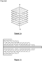
- Figure 1a shows a common lay up configuration for an article having a constant cross section whereby unidirectional plies are orientated in a specific direction with respect to an X axis as indicated in the figure. It is known that when building such an arrangement, consideration must be given to the symmetrical nature of the stack, to minimise bending or warping. However, for devices which have a varying cross section, extra care is needed to achieve the desired thickness at specific locations along the length of the device. Typically, this is achieved by a graduated layered arrangement whereby smaller lengths of plies are placed in a stepped sequence on top of longer lengths of ply as shown in Figure 1b . Disadvantageously, such an arrangement can lead to shearing or delamination at the exterior facing surface due to the graduated exposed edges; this may lead to device failure or, in medical devices, exposure of filler material to patient tissue.
- an implantable medical device according to claim 1.
- the first portion comprises at least one ply.
- the first portion comprises a first ply and a second ply.
- the first and second plies form a part of the surface of the body.
- the first portion forms substantially the whole of the surface of the body.
- the surface of the body is an exterior facing surface thereof.
- the exterior facing surface is typically that surface of a medical device that lays adjacent patient bone or tissue in situ.
- the packing portion is adjacent the first portion.
- the packing portion comprises at least one packing ply, preferably a plurality of packing plies. Said plies may be of the same length as at least one ply of the first portion.
- the plurality of packing plies is configured in a lay-up arrangement, preferably having at least one line of symmetry, preferably about a longitudinal axis of the body.
- the or each packing ply is adjacent the first ply and/or the second ply of the first portion.
- a packing ply is adjacent at least a part of the insert. Most preferably, the or each packing ply is arranged to encase the insert.
- the insert comprises at least one insert ply.
- a plurality of insert plies is provided.
- the or each insert ply is of a different length to a neighbouring insert ply.
- the or each insert ply is of a different length to the or each packing ply.
- the or each insert ply is of a different length to the first and/or second ply of the first portion.
- the or each insert ply is less than 90% of the length of the or each packing ply, preferably less than 50%, preferably less than 20%.
- the or each insert ply is less than 90% of the length of the or each first or second ply of the first portion, preferably less than 50%.
- said plies are arranged in a randomly stacked configuration.
- such configuration has no line of symmetry about the longitudinal axis of the body.
- the insert is substantially wholly encapsulated within the packing portion. Further most preferably, at least one packing ply may be provided between the or each insert ply.
- provision of the insert within the packing portion minimises the risk of exposure of filler material to a patient.
- the provision of the insert in the packing portion minimises the risk of delamination and reduces the risk of shearing occurring at the surface of the device. This is particularly critical for implantable medical devices which are in contact with tissue or bone.
- the first portion, and/or the packing portion, and/or the insert comprise composite material.
- the composite material comprises a fibrous filler and a polymeric material.
- the composite material suitably includes at least 30 vol%, more preferably at least 40 vol%, especially at least 50vol% of the polymeric material.
- Said composite material includes up to 70vol% of carbon fibres and it may include up to 65vol%, or up to 50vol% of carbon fibres.
- Said composite material may include to 50vol% of said polymeric material and 40 to 65vol% of carbon fibre.
- said composite material comprises 40vol% of polymeric material of formula I.
- a disclosed polymeric material is a polyaryletherketone having a repeat unit of formula (I) where t1 and w1 independently represent 0 or 1 and v1 represents 0, 1 or 2.
- Said polyaryletherketone suitably includes at least 90, 95 or 99 mol % of repeat unit of formula I.
- said polymeric material is polyetheretherketone or PEEK.
- said composite material comprises 38wt% of polymeric material of formula I and 62wt% carbon fibre.
- Said polyaryletherketone may have a Notched Izod Impact Strength (specimen 80mm x 10mm x 4mm with a cut 0.25mm notch (Type A), tested at 23°C, in accordance with ISO180) of at least 4KJm -2 , preferably at least 5KJm -2 , more preferably at least 6KJm -2 .
- Said Notched Izod Impact Strength measured as aforesaid, may be less than 10KJm -2 , suitably less than 8KJm -2 ..
- the Notched Izod Impact Strength measured as aforesaid, may be at least 3KJm -2 , suitably at least 4KJm -2 , preferably at least 5KJm -2 . Said impact strength may be less than 50 KJm -2 , suitably less than 30KJm -2 .
- Said polyaryletherketone has a melt viscosity (MV) of at least 0.06 kNsm -2 , preferably has a MV of at least 0.09 kNsm -2 , more preferably at least 0.12 kNsm -2 .
- Said polyaryletherketone has a MV of less than 0.5 kNsm -2 .
- Said polyaryletherketone may have a MV in the range 0.09 to 0.5 kNsm -2 , preferably in the range 0.1 to 0.3 kNsm -2 , preferably having a MV in the range 0.1 to 0.2 kNsm -2 .
- An MV of 0.15 kNsm -2 has been found to be particularly advantageous.
- MV is measured using capillary rheometry operating at 400°C at a shear rate of 1000s -1 using a tungsten carbide die, 0.5mmx3.175mm.
- Said polyaryletherketone may be amorphous or semi-crystalline. It is preferably crystallisable. It is preferably semi-crystalline.
- the level and extent of crystallinity in a polymer is preferably measured by wide angle X-ray diffraction (also referred to as Wide Angle X-ray Scattering or WAXS), for example as described by Blundell and Osborn (Polymer 24 , 953, 1983).
- WAXS Wide Angle X-ray Scattering
- crystallinity may be assessed by Differential Scanning Calorimetry (DSC).
- the level of crystallinity of said polyaryletherketone may be at least 1%, suitably at least 3%, preferably at least 5% and more preferably at least 10%. In especially preferred embodiments, the crystallinity may be greater than 25%. It may be less than 50% or less than 40%.
- the main peak of the melting endotherm (Tm) of said polyaryletherketone (if crystalline) may be at least 300°C.
- the composite material may include one or more further components. It may include up to 15wt%, preferably up to 10wt% of other components. According to the invention, an X-ray contrast material in form of barium sulphate is used.
- each said ply of the first portion and/or the packing portion and/or the insert comprises the composite material having a thickness from 10 ⁇ m to 1mm, preferably 100 to 300 ⁇ m, most preferably from 140 to 200 ⁇ m.
- the fibres used in the composite layer may be selected from inorganic fibrous materials and non-melting and high-melting organic fibrous materials, such as aramid fibres, carbon fibre and the like.
- the fibres may be selected from glass fibre, carbon fibre, silica fibre, zirconia fibre, silicon nitride fibre, boron fibre, fluorocarbon resin fibre and potassium titanate fibre. Most preferred fibres are carbon fibres. Nanofibres may be employed.
- a coating is provided on the body.
- the coating is adjacent at least a part of the first portion.
- the coating comprises a first coating layer and a second coating layer.
- the first coating layer is provided on an upper surface of the body.
- the second coating layer is provided on a lower surface of the body.
- the first coating layer is remote from the second coating layer.
- the first coating layer does not touch the second coating layer.
- the first and second coating layers are separate from each other such that the first coating layer forms an upper face of the device and the second coating layer forms a lower face of the device.
- the ends of the device body are substantially free of both the first and second coating layers.
- the coating may form substantially the whole of the exterior surface.
- the or each coating layer is between 10 ⁇ m and 1mm thickness.
- the or each layer is between 100 ⁇ m and 600 ⁇ m, most preferably substantially 200 ⁇ m. Thicknesses are suitably as measured by a film thickness gauge such as a Hanatek FT3 gauge.
- the coating is preferably a radiopaque material which may be any material which when added to a polymeric material increases the radiopacity of the combination.
- Said radiopaque material preferably improves the imageability of the first polymeric material when imaged using both CT and MRI techniques.
- Said radiopaque material may comprise a metal, an inorganic material or an iodine-containing organic material.
- the coating comprises barium sulphate and a polyaryletherketone.
- the polyaryletherketone is PEEK.
- the coating includes at least 1 wt%, suitably at least 2 wt%, preferably at least 3 wt% barium sulphate.
- the amount of barium sulphate is between 6 wt% and 60 wt%.
- the or each, preferably both, said coating layers comprise substantially 20wt% barium sulphate.
- Said barium sulphate is preferably intimately mixed with the PEEK polymer, suitably so the barium sulphate and said polymer define a substantially homogenous mixture.
- each coating layer suitably has a melt viscosity (MV) of at least 0.06 kNsm -2 , preferably has a MV of at least 0.09 kNsm -2 , more preferably at least 0.12 kNsm -2 .
- said PEEK has a MV between 0.1 and 0.5 kNsm -2 .
- the PEEK has an MV between 0.35 and 0.45 kNsm -2 .
- Said PEEK may have the same MV as the composite polymeric material of the first portion and/or the packing portion, and/or the insert.
- the or each coating layer includes less than 10 wt% of fibres, for example less than 5 wt% or less than 0.5 wt%. It preferably includes no fibres.
- Said coating may be made by any suitable means known in the prior art, such as by melt extrusion of the polymer through a wide, T-shaped film die with adjustable gap.
- the or each coating layer may be a metal foil, for example comprising titanium, tungsten or zirconium oxide.
- the implantable medical device is a plate, or a nail or a screw. The implantable medical device is most preferably an implantable trauma plate for fracture fixation.
- the first surface is an exterior facing surface of the device.
- the second ply forms a second exterior facing surface of the device.
- the molding step (f) is a compression molding step.
- step (f) takes place at temperatures between 350°C and 400°C, preferably between 350 and 380°C, most preferably between 350°C and 370°C.
- the method comprises a step (g) which takes place after step (f) wherein the body is rapidly cooled, preferably to between 140°C and 200°C.
- the method includes a further step (h) of applying a coating comprising a first coating layer and a second coating layer to the device.
- the coating layer comprises a radiopaque marker, most preferably barium sulphate as hereinbefore described.
- the coating step (h) takes place after step (e).
- the coating may be applied after step (f).
- the method includes a further molding step (i) for molding the coating to the layup to provide the finished device.
- the first coating layer and the second coating layer are remote from each other.
- a radiopaque marker is provided on the surface of the device.
- step (i) takes place under pressure, preferably between 2 and 8MPa.
- the molding step takes place at temperatures between 340°C and 400°C, most preferably between 350°C and 370°C.
- the method further includes a step of trimming the device obtained from the or each molding step (f) or (i) to remove any flashing.
- the method is carried out by an automated process.
- an implantable medical device having a body comprising a composite material, the body having a variable cross section along a length, the body comprising a first portion, a packing portion, and a coating, the coating forming at least part of an exterior surface of the body, wherein an insert is provided in the packing portion, the insert providing an increased thickness to at least a part of the body.
- the coating includes at least 1 wt%, suitably at least 2 wt%, preferably between 6 and 60wt% barium sulphate.
- the device comprises an additional material operable to reduce bacterial activity, or to encourage bone growth.
- the material may be porous titanium or hydroxyapatite.
- Said material may be in the form of a layer of film.
- Figures 1a and 1b show typical lay-up arrangements as previously discussed.
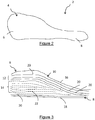
- Figure 2 shows a device 2 according to the present invention.
- the device 2 is an implantable medical device that comprises a body 4 having a head 6 and a tail 8. It can be seen that the cross sectional area of the device 2 varies along the longitudinal length of the body 4, with the head 6 being much greater in thickness compared to the tail 8.
- the device 2 comprises a first portion 10, a packing portion 12 and an insert 14.
- the first portion 10 includes a first ply 16 and a second ply 18.
- the first and second plies 16,18 together form the exterior surface of the device 2.
- the packing portion 12 comprises a plurality of packing plies 20 which are adjacent the inner face of the first portion 10. As shown in Figure 3 , the packing plies 20 are located either side of the insert 14, and adjacent the first and second plies 16,18. The packing plies 20 are symmetrical about the longitudinal axis of the body 4. In an alternative embodiment, packing plies are provided between insert plies.
- the insert 14 comprises at least one insert ply 22.
- a plurality of insert plies 22 (represented by dashed lines) is provided in the device 2.
- the or each insert ply 22 is shorter in length when compared to the packing plies 20.
- the packing plies 20 surround the insert 14, encasing it within the packing portion 12 as shown most clearly in Figure 6b .
- FIG. 4 An embodiment of a lay-up arrangement of the head 6 of the medical device 2 is shown in greater detail in Figure 4 and 5 .
- the first ply 16 and second ply 18 form the exterior facing surface of the body 4.
- Packing plies 20 are located adjacent said first and second plies 16,18.
- the insert 14 is located between the packing plies 20.
- the insert plies 22 are non-symmetrical about an axis A, being of varying lengths to one another, and each being shorter in length than the adjacent packing ply 20. Provision of a non-symmetrical layering of the insert plies 22 ensures a greater degree of consistency in the overall cross section required by the head 6.
- Figure 5 shows the lay-up arrangement of the plies, with respect to the X axis, in the head 6 and tail 8.
- the first and second plies 16, 18 are placed at 0°, and the packing plies 20 are orientated at +45°, 0°, -45°, 0°, 90°, -45°, 0°, +45°.
- the head 6 has a greater thickness than the tail 8 and so inserts 14 are provided within the packing portion 20 at locations indicated by the arrows in the figure. Each insert 14 is orientated at 0°.
- Such an arrangement achieves both the required cross sectional area required by the varying thickness of the device but also, essentially, ensures that the surface of the device comprises complete plies in contrast to the device shown in Figure 1b . In so doing, the risk of delamination or shearing occurring at the exterior surface of the device 2 is minimised.
- FIGS. 6 show an embodiment of a medical device 100 according to the invention. It will be understood by the reader that like reference numerals have been used to reference like parts shown in the previous figures.
- the device 100 comprises a body 104 having a first portion 110, a packing portion 120, and an insert 114.
- a coating 130 is located on the first portion 110.
- the coating 130 comprises a first coating layer 132 and a second coating layer 134.
- the first coating layer 132 lays adjacent the first ply 116
- the second coating layer 134 lays adjacent the second ply 118.
- Said coating layers 132, 134 do not extend around the whole surface of the body 104 but cover only an upper surface and a lower surface thereof.
- Figure 6a shows that the layup arrangement provided by the disclosure ensures that the insert 114 is fully encased by the packing plies 120.
- the coating 130 comprises a barium sulphate/PEEK composite as will be described in further detail below.
- the plies of composite material of PEEK and carbon fibres which make up the body 4, 104 are prepared according to the following method:
- the carbon fibre was an IM7 12K tow from Hexcel Inc.
- the carbon fibre ply is 62% by weight of carbon fibre, 38% by weight of PEEK-OPTIMA® Natural LT3 obtained from Invibio Biomaterial Solutions Ltd, with a Tm of 340°C and MV of 0.15.
- MV is measured using capillary rheometry operating at 400°C at a shear rate of 1000s -1 using a circular cross-section tungsten carbide die of 0.5mm capillary diameter x 3.175mm capillary length.
- Modelling data was generated using Dassault Systems CATIATM software, to provide an indication of composite lay-up.
- the plies of the first portion, the packing portion and the insert were then cut.
- the plies were then assembled according to an embodiment of the invention shown in Figure 5 wherein a second ply 18, 118 of the first portion 10,110 was orientated and positioned to form a lower surface of the device; a first plurality of packing plies 20,120 were placed on top of the second ply 18,118; the insert plies 22,122 were then positioned within said plurality 20,120 such that the insert plies 22,122 were encapsulated therein; and a first ply 16,116 of the first portion 10,110 was positioned on top of the plurality to form an upper surface of the body 4,104.
- the lay-up arrangement was compression molded using a PEI Lab Compression Moulder at 370°C @ 2Mpa press force then rapidly cooled under pressure.
- the laminated device 2,100 was then removed from the mold and machined as required.
- the coating 130 comprises substantially 20% barium sulphate which is intimately mixed with PEEK polymer having an MV of 0.45 kNsm -2 commercially available from Invibio Limited, UK under the trade mark PEEK-OPTIMA Image Contrast. Each layer of the coating is substantially 200 ⁇ m in thickness.
- the barium sulphate used was grade 10175, extra pure for X-ray diagnosis, from Merck. Barium sulphate was added to PEEK-OPTIMA via an extrusion compounding process.
- the barium sulphate can be gravimetrically metered and fed through a side feeder into a twin screw extruder, where it is combined with plasticized polymer melt and intimately mixed to provide a uniform dispersion of the filler within the polymer.
- the barium sulphate was added to 20% by weight of the polymer. Extrusion of this mixture through a die generates strands or laces that cool and solidify before being chopped into small granules in preparation for subsequent processing.
- the composite layer 130 is made into a tape in a conventional manner. For example, the manufacture of tapes is described in, for instance, US Patent 4,626,306 where an aqueous dispersion impregnation method is set out.
- a 200 ⁇ m tape as prepared above was placed on a base and an upper face of the body so as to sandwich the body therein.
- the body was placed in a compression mold tool and heated to 360°C under a pressure of 2KN. Once the temperature was reached, the mold tool temperature was dropped to 220°C at a controlled cooling rate using thermocouples to monitor the temperature. The finished device was removed from the mold tool and trimmed to remove unwanted flashing.
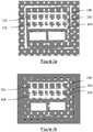
- Figure 7a shows an X-Ray images of five 2mm composite plates made according to the above procedure for preparing PEEK carbon fibre composites.
- Plate 150 is a reference plate having no barium sulphate film coating.
- Plate 152 is a PEEK composite having a 100 ⁇ m barium sulphate coating layer, made according to the above, deposited on either side of the plate (total film thickness 0.2mm).
- Plate 154 has a 200 ⁇ m barium sulphate coating layer (total 0.4mm); plate 156 has a 300 ⁇ m coating layer (total 0.6mm) and plate 158 has a 400 ⁇ m coating layer (total 0.8mm).
- plate 158 having the 400 ⁇ m film on either side of the plate provides the brightest contrast as would be expected.
- a contrast removes the advantage of a clinician being able to view a fracture through the device.
- a thickness of barium sulphate reduces the mechanical properties of the overall device which has a restricted overall thickness for implantation; the thicker the barium sulphate layers means that less composite layers can be used in the overall structure.
- the images show a sufficient contrast when using 200 ⁇ m coating layer either side of the body - plate 154.
- Figure 7b shows a 5mm plate with the same layup to those of Figure 7a .
- Plate 254 has the 200 ⁇ m barium sulphate film either side of the body; this shows sufficient contrast needed for medical use.
- Figures 8a and 8b show SEMs (taken using a Hitachi TM300 15KV) of a device according to the present invention without a barium sulphate film.
- the exterior surface 360 of the device comprises a complete length of composite ply which extends over the body.
- the SEMs show a smoothed surface. Consequently, the risk of shearing of the exterior surface is greatly minimised which in turn reduces the risk of carbon fibre exposure.
- Figures 9a and 9b show SEMs (taken using a Hitachi TM300 15KV) of a typical prior art device.
- an exterior surface 380 of a device, formed by graduated plies as shown in Figure 1b has a sheared or serrated finish. It can be seen that the carbon fibre in the composite is exposed.
- lay-up arrangement as hereinbefore described allows for the creation of a device of variable cross section, which minimises the risk of shearing at an exposed surface.
- Radiopaque coating enables greater visibility of a medical implant by medical imaging techniques during and following implantation. During implantation, this assists the surgeon in, for example, screw placement. In addition, the surgeon is able to assess location of the device and be alert to possible breaks in the device.
Landscapes
- Health & Medical Sciences (AREA)
- Chemical & Material Sciences (AREA)
- Life Sciences & Earth Sciences (AREA)
- Engineering & Computer Science (AREA)
- Orthopedic Medicine & Surgery (AREA)
- Veterinary Medicine (AREA)
- Public Health (AREA)
- General Health & Medical Sciences (AREA)
- Animal Behavior & Ethology (AREA)
- Composite Materials (AREA)
- Surgery (AREA)
- Medicinal Chemistry (AREA)
- Epidemiology (AREA)
- Transplantation (AREA)
- Oral & Maxillofacial Surgery (AREA)
- Dermatology (AREA)
- Mechanical Engineering (AREA)
- Molecular Biology (AREA)
- Nuclear Medicine, Radiotherapy & Molecular Imaging (AREA)
- Biomedical Technology (AREA)
- Heart & Thoracic Surgery (AREA)
- Medical Informatics (AREA)
- Neurology (AREA)
- Materials Engineering (AREA)
- Inorganic Chemistry (AREA)
- Prostheses (AREA)
- Materials For Medical Uses (AREA)
- Chemical Kinetics & Catalysis (AREA)
- Polymers & Plastics (AREA)
- Organic Chemistry (AREA)
Description
- The present invention relates to an implantable medical device. The invention further relates to a method of manufacturing such a device.
- Devices made from polymeric composite material are known. Such material has the advantage over a metal counterpart because it provides improved flexibility to the device whilst maintaining the strength required for load bearing. In addition, implantable polymeric devices are known to be less likely to cause bone deterioration in the patient.
- A typical polymeric composite arrangement comprises a plurality of plies of material which are compression molded together.
Figure 1a shows a common lay up configuration for an article having a constant cross section whereby unidirectional plies are orientated in a specific direction with respect to an X axis as indicated in the figure. It is known that when building such an arrangement, consideration must be given to the symmetrical nature of the stack, to minimise bending or warping. However, for devices which have a varying cross section, extra care is needed to achieve the desired thickness at specific locations along the length of the device. Typically, this is achieved by a graduated layered arrangement whereby smaller lengths of plies are placed in a stepped sequence on top of longer lengths of ply as shown inFigure 1b . Disadvantageously, such an arrangement can lead to shearing or delamination at the exterior facing surface due to the graduated exposed edges; this may lead to device failure or, in medical devices, exposure of filler material to patient tissue. - It is an object of the present invention to provide an implantable medical device having an improved composite structure to minimise the risk of delamination or shearing of the device. It is a further object of the invention to provide an implantable medical device having an improved composite structure to minimise tissue contact with composite filler.
- According to an aspect of the present invention there is provided an implantable medical device according to claim 1.
- Preferably, the first portion comprises at least one ply. Preferably, the first portion comprises a first ply and a second ply. Preferably, the first and second plies form a part of the surface of the body. In a most preferred embodiment, the first portion forms substantially the whole of the surface of the body.
- In a preferred arrangement, the surface of the body is an exterior facing surface thereof. The exterior facing surface is typically that surface of a medical device that lays adjacent patient bone or tissue in situ.
- Preferably, the packing portion is adjacent the first portion. Preferably, the packing portion comprises at least one packing ply, preferably a plurality of packing plies. Said plies may be of the same length as at least one ply of the first portion. Preferably, the plurality of packing plies is configured in a lay-up arrangement, preferably having at least one line of symmetry, preferably about a longitudinal axis of the body. Preferably, the or each packing ply is adjacent the first ply and/or the second ply of the first portion. Preferably, a packing ply is adjacent at least a part of the insert. Most preferably, the or each packing ply is arranged to encase the insert.
- Preferably, the insert comprises at least one insert ply. Preferably, a plurality of insert plies is provided. Preferably, the or each insert ply is of a different length to a neighbouring insert ply. Preferably, the or each insert ply is of a different length to the or each packing ply. Preferably, the or each insert ply is of a different length to the first and/or second ply of the first portion. Preferably, the or each insert ply is less than 90% of the length of the or each packing ply, preferably less than 50%, preferably less than 20%. Preferably, the or each insert ply is less than 90% of the length of the or each first or second ply of the first portion, preferably less than 50%.
- Preferably, when a plurality of insert plies is provided, said plies are arranged in a randomly stacked configuration. Most preferably, such configuration has no line of symmetry about the longitudinal axis of the body.
- In a most preferred arrangement, the insert is substantially wholly encapsulated within the packing portion. Further most preferably, at least one packing ply may be provided between the or each insert ply.
- Advantageously, provision of the insert within the packing portion minimises the risk of exposure of filler material to a patient.
- Advantageously, the provision of the insert in the packing portion minimises the risk of delamination and reduces the risk of shearing occurring at the surface of the device. This is particularly critical for implantable medical devices which are in contact with tissue or bone.
- Preferably, the first portion, and/or the packing portion, and/or the insert comprise composite material.
- Preferably, the composite material comprises a fibrous filler and a polymeric material.
- The composite material suitably includes at least 30 vol%, more preferably at least 40 vol%, especially at least 50vol% of the polymeric material. Said composite material includes up to 70vol% of carbon fibres and it may include up to 65vol%, or up to 50vol% of carbon fibres. Said composite material may include to 50vol% of said polymeric material and 40 to 65vol% of carbon fibre. In a preferred embodiment said composite material comprises 40vol% of polymeric material of formula I.
- A disclosed polymeric material is a polyaryletherketone having a repeat unit of formula (I)

- Said polyaryletherketone suitably includes at least 90, 95 or 99 mol % of repeat unit of formula I.
- According to the invention, said polymeric material is polyetheretherketone or PEEK.
- In an embodiment, said composite material comprises 38wt% of polymeric material of formula I and 62wt% carbon fibre.
- Said polyaryletherketone may have a Notched Izod Impact Strength (specimen 80mm x 10mm x 4mm with a cut 0.25mm notch (Type A), tested at 23°C, in accordance with ISO180) of at least 4KJm-2, preferably at least 5KJm-2, more preferably at least 6KJm-2. Said Notched Izod Impact Strength, measured as aforesaid, may be less than 10KJm-2, suitably less than 8KJm-2.. The Notched Izod Impact Strength, measured as aforesaid, may be at least 3KJm-2, suitably at least 4KJm-2, preferably at least 5KJm-2. Said impact strength may be less than 50 KJm-2, suitably less than 30KJm-2.
- Said polyaryletherketone has a melt viscosity (MV) of at least 0.06 kNsm-2, preferably has a MV of at least 0.09 kNsm-2, more preferably at least 0.12 kNsm-2. Said polyaryletherketone has a MV of less than 0.5 kNsm-2.
- Said polyaryletherketone may have a MV in the range 0.09 to 0.5 kNsm-2, preferably in the range 0.1 to 0.3 kNsm-2, preferably having a MV in the range 0.1 to 0.2 kNsm-2. An MV of 0.15 kNsm-2 has been found to be particularly advantageous. MV is measured using capillary rheometry operating at 400°C at a shear rate of 1000s-1 using a tungsten carbide die, 0.5mmx3.175mm.
- Said polyaryletherketone may be amorphous or semi-crystalline. It is preferably crystallisable. It is preferably semi-crystalline. The level and extent of crystallinity in a polymer is preferably measured by wide angle X-ray diffraction (also referred to as Wide Angle X-ray Scattering or WAXS), for example as described by Blundell and Osborn (Polymer 24, 953, 1983). Alternatively, crystallinity may be assessed by Differential Scanning Calorimetry (DSC).
- The level of crystallinity of said polyaryletherketone may be at least 1%, suitably at least 3%, preferably at least 5% and more preferably at least 10%. In especially preferred embodiments, the crystallinity may be greater than 25%. It may be less than 50% or less than 40%.
- The main peak of the melting endotherm (Tm) of said polyaryletherketone (if crystalline) may be at least 300°C.
- The composite material may include one or more further components. It may include up to 15wt%, preferably up to 10wt% of other components. According to the invention, an X-ray contrast material in form of barium sulphate is used.
- Preferably, each said ply of the first portion and/or the packing portion and/or the insert comprises the composite material having a thickness from 10µm to 1mm, preferably 100 to 300 µm, most preferably from 140 to 200 µm.
- The fibres used in the composite layer may be selected from inorganic fibrous materials and non-melting and high-melting organic fibrous materials, such as aramid fibres, carbon fibre and the like. For instance, the fibres may be selected from glass fibre, carbon fibre, silica fibre, zirconia fibre, silicon nitride fibre, boron fibre, fluorocarbon resin fibre and potassium titanate fibre. Most preferred fibres are carbon fibres. Nanofibres may be employed.
- Preferably, a coating is provided on the body. Preferably, the coating is adjacent at least a part of the first portion. Preferably, the coating comprises a first coating layer and a second coating layer. Preferably, the first coating layer is provided on an upper surface of the body. Preferably, the second coating layer is provided on a lower surface of the body. Preferably, the first coating layer is remote from the second coating layer. Preferably, the first coating layer does not touch the second coating layer.
- In a preferred embodiment, the first and second coating layers are separate from each other such that the first coating layer forms an upper face of the device and the second coating layer forms a lower face of the device. The ends of the device body are substantially free of both the first and second coating layers. The coating may form substantially the whole of the exterior surface.
- Preferably, the or each coating layer is between 10µm and 1mm thickness. Preferably, the or each layer is between 100µm and 600µm, most preferably substantially 200µm. Thicknesses are suitably as measured by a film thickness gauge such as a Hanatek FT3 gauge.
- The coating is preferably a radiopaque material which may be any material which when added to a polymeric material increases the radiopacity of the combination. Said radiopaque material preferably improves the imageability of the first polymeric material when imaged using both CT and MRI techniques. Said radiopaque material may comprise a metal, an inorganic material or an iodine-containing organic material.
- Preferably, the coating comprises barium sulphate and a polyaryletherketone. Most preferably, the polyaryletherketone is PEEK.
- Preferably, the coating includes at least 1 wt%, suitably at least 2 wt%, preferably at least 3 wt% barium sulphate. Preferably, the amount of barium sulphate is between 6 wt% and 60 wt%. In a preferred embodiment, the or each, preferably both, said coating layers comprise substantially 20wt% barium sulphate.
- Said barium sulphate is preferably intimately mixed with the PEEK polymer, suitably so the barium sulphate and said polymer define a substantially homogenous mixture.
- Said PEEK in the or preferably each coating layer suitably has a melt viscosity (MV) of at least 0.06 kNsm-2, preferably has a MV of at least 0.09 kNsm-2, more preferably at least 0.12 kNsm-2. Preferably, said PEEK has a MV between 0.1 and 0.5 kNsm-2. Preferably, the PEEK has an MV between 0.35 and 0.45 kNsm-2. Said PEEK may have the same MV as the composite polymeric material of the first portion and/or the packing portion, and/or the insert.
- Preferably, the or each coating layer includes less than 10 wt% of fibres, for example less than 5 wt% or less than 0.5 wt%. It preferably includes no fibres. Said coating may be made by any suitable means known in the prior art, such as by melt extrusion of the polymer through a wide, T-shaped film die with adjustable gap. The or each coating layer may be a metal foil, for example comprising titanium, tungsten or zirconium oxide. Preferably, the implantable medical device is a plate, or a nail or a screw. The implantable medical device is most preferably an implantable trauma plate for fracture fixation.
- According to a second aspect of the invention, there is provided a method of manufacturing an implantable medical device according to claim 11.
- Preferably, the first surface is an exterior facing surface of the device. Preferably, the second ply forms a second exterior facing surface of the device.
- Preferably, the molding step (f) is a compression molding step. Preferably, step (f) takes place at temperatures between 350°C and 400°C, preferably between 350 and 380°C, most preferably between 350°C and 370°C.
- Preferably, the method comprises a step (g) which takes place after step (f) wherein the body is rapidly cooled, preferably to between 140°C and 200°C.
- Preferably, the method includes a further step (h) of applying a coating comprising a first coating layer and a second coating layer to the device. Preferably, the coating layer comprises a radiopaque marker, most preferably barium sulphate as hereinbefore described. Preferably, the coating step (h) takes place after step (e). The coating may be applied after step (f). Preferably, the method includes a further molding step (i) for molding the coating to the layup to provide the finished device.
- Preferably, the first coating layer and the second coating layer are remote from each other. In this manner, advantageously, a radiopaque marker is provided on the surface of the device.
- Preferably, step (i) takes place under pressure, preferably between 2 and 8MPa. Preferably, the molding step takes place at temperatures between 340°C and 400°C, most preferably between 350°C and 370°C.
- Preferably, the method further includes a step of trimming the device obtained from the or each molding step (f) or (i) to remove any flashing.
- Preferably, the method is carried out by an automated process.
- According to a further aspect of the present disclosure there is provided an implantable medical device having a body comprising a composite material, the body having a variable cross section along a length, the body comprising a first portion, a packing portion, and a coating, the coating forming at least part of an exterior surface of the body, wherein an insert is provided in the packing portion, the insert providing an increased thickness to at least a part of the body.
- Preferably, the coating includes at least 1 wt%, suitably at least 2 wt%, preferably between 6 and 60wt% barium sulphate.
- Preferably, the device comprises an additional material operable to reduce bacterial activity, or to encourage bone growth. The material may be porous titanium or hydroxyapatite. Said material may be in the form of a layer of film.
- All of the features described herein may be combined with any one of the above aspects, in any combination.
- An embodiment of the invention will now be described, by way of example only, with reference to the accompanying drawings, wherein:
-
Figure 1a shows a schematic perspective view of a typical composite lay up arrangement; -
Figure 1b shows a schematic sectional side view of a further typical composite lay up arrangement; -
Figure 2 shows a schematic side view of a medical device according to the present invention; -
Figure 3 shows a schematic sectional side view of a part of the medical device ofFigure 2 ; -
Figure 4 shows an embodiment of a lay-up arrangement of part of a device according to the present invention; -
Figure 5 shows an embodiment of a lay-up arrangement of a device according to the present invention; -
Figure 6a and 6b show schematic sectional side views of a device according to the present invention; -
Figures 7a and 7b are X-ray images of a 2mm plate and a 5mm plate respectively, in accordance with the present invention; -
Figures 8a and 8b show SEM images of part of a device according to the invention; and -
Figures 9a and 9b show SEM images of part of a prior art device. -
Figures 1a and 1b show typical lay-up arrangements as previously discussed.Figure 2 shows adevice 2 according to the present invention. Thedevice 2 is an implantable medical device that comprises abody 4 having ahead 6 and atail 8. It can be seen that the cross sectional area of thedevice 2 varies along the longitudinal length of thebody 4, with thehead 6 being much greater in thickness compared to thetail 8. - The
device 2 comprises afirst portion 10, a packingportion 12 and aninsert 14. Thefirst portion 10 includes afirst ply 16 and asecond ply 18. The first andsecond plies device 2. - The packing
portion 12 comprises a plurality of packing plies 20 which are adjacent the inner face of thefirst portion 10. As shown inFigure 3 , the packing plies 20 are located either side of theinsert 14, and adjacent the first andsecond plies body 4. In an alternative embodiment, packing plies are provided between insert plies. - The
insert 14 comprises at least oneinsert ply 22. In the embodiment shown inFigure 3 , a plurality of insert plies 22 (represented by dashed lines) is provided in thedevice 2. The or each insert ply 22 is shorter in length when compared to the packing plies 20. In so doing, the packing plies 20 surround theinsert 14, encasing it within the packingportion 12 as shown most clearly inFigure 6b . - An embodiment of a lay-up arrangement of the
head 6 of themedical device 2 is shown in greater detail inFigure 4 and 5 . InFigure 4 , thefirst ply 16 andsecond ply 18 form the exterior facing surface of thebody 4. Packing plies 20 are located adjacent said first andsecond plies insert 14 is located between the packing plies 20. It can be seen, that the insert plies 22 are non-symmetrical about an axis A, being of varying lengths to one another, and each being shorter in length than the adjacent packing ply 20. Provision of a non-symmetrical layering of the insert plies 22 ensures a greater degree of consistency in the overall cross section required by thehead 6. -
Figure 5 shows the lay-up arrangement of the plies, with respect to the X axis, in thehead 6 andtail 8. Specifically, in thetail 8, the first andsecond plies head 6 has a greater thickness than thetail 8 and so inserts 14 are provided within the packingportion 20 at locations indicated by the arrows in the figure. Eachinsert 14 is orientated at 0°. - Such an arrangement achieves both the required cross sectional area required by the varying thickness of the device but also, essentially, ensures that the surface of the device comprises complete plies in contrast to the device shown in
Figure 1b . In so doing, the risk of delamination or shearing occurring at the exterior surface of thedevice 2 is minimised. -
Figures 6 show an embodiment of amedical device 100 according to the invention. It will be understood by the reader that like reference numerals have been used to reference like parts shown in the previous figures. Thedevice 100 comprises abody 104 having a first portion 110, a packingportion 120, and aninsert 114. Acoating 130 is located on the first portion 110. Thecoating 130 comprises afirst coating layer 132 and asecond coating layer 134. Thefirst coating layer 132 lays adjacent thefirst ply 116, and thesecond coating layer 134 lays adjacent thesecond ply 118. Said coating layers 132, 134 do not extend around the whole surface of thebody 104 but cover only an upper surface and a lower surface thereof.Figure 6a shows that the layup arrangement provided by the disclosure ensures that theinsert 114 is fully encased by the packing plies 120. - The
coating 130 comprises a barium sulphate/PEEK composite as will be described in further detail below. - The plies of composite material of PEEK and carbon fibres which make up the
body - The carbon fibre was an IM7 12K tow from Hexcel Inc. The carbon fibre ply is 62% by weight of carbon fibre, 38% by weight of PEEK-OPTIMA® Natural LT3 obtained from Invibio Biomaterial Solutions Ltd, with a Tm of 340°C and MV of 0.15. MV is measured using capillary rheometry operating at 400°C at a shear rate of 1000s-1 using a circular cross-section tungsten carbide die of 0.5mm capillary diameter x 3.175mm capillary length.
- Modelling data was generated using Dassault Systems CATIA™ software, to provide an indication of composite lay-up. The plies of the first portion, the packing portion and the insert were then cut. The plies were then assembled according to an embodiment of the invention shown in
Figure 5 wherein asecond ply - The
coating 130 comprises substantially 20% barium sulphate which is intimately mixed with PEEK polymer having an MV of 0.45 kNsm-2 commercially available from Invibio Limited, UK under the trade mark PEEK-OPTIMA Image Contrast. Each layer of the coating is substantially 200µm in thickness. The barium sulphate used was grade 10175, extra pure for X-ray diagnosis, from Merck. Barium sulphate was added to PEEK-OPTIMA via an extrusion compounding process. By way of example, the barium sulphate can be gravimetrically metered and fed through a side feeder into a twin screw extruder, where it is combined with plasticized polymer melt and intimately mixed to provide a uniform dispersion of the filler within the polymer. The barium sulphate was added to 20% by weight of the polymer. Extrusion of this mixture through a die generates strands or laces that cool and solidify before being chopped into small granules in preparation for subsequent processing. In the present disclosure, thecomposite layer 130 is made into a tape in a conventional manner. For example, the manufacture of tapes is described in, for instance,US Patent 4,626,306 where an aqueous dispersion impregnation method is set out. Other descriptions for the formation of such tapes may be found in "Impregnation Techniques for Thermoplastic Matrix Composites" - A Miller and A G Gibson, Polymer & Polymer Composites 4 (7) 459 - 481 (1996), in patent application publicationEP 0592473 A1 and specifically for melt impregnation in the patent application publicationsEP 0102158 A2 orEP 0102159 A2 . - A 200µm tape as prepared above was placed on a base and an upper face of the body so as to sandwich the body therein. The body was placed in a compression mold tool and heated to 360°C under a pressure of 2KN. Once the temperature was reached, the mold tool temperature was dropped to 220°C at a controlled cooling rate using thermocouples to monitor the temperature. The finished device was removed from the mold tool and trimmed to remove unwanted flashing.
-
Figure 7a shows an X-Ray images of five 2mm composite plates made according to the above procedure for preparing PEEK carbon fibre composites.Plate 150 is a reference plate having no barium sulphate film coating.Plate 152 is a PEEK composite having a 100µm barium sulphate coating layer, made according to the above, deposited on either side of the plate (total film thickness 0.2mm).Plate 154 has a 200µm barium sulphate coating layer (total 0.4mm);plate 156 has a 300µm coating layer (total 0.6mm) andplate 158 has a 400µm coating layer (total 0.8mm). - It can be seen that
plate 158 having the 400µm film on either side of the plate provides the brightest contrast as would be expected. However, such a contrast removes the advantage of a clinician being able to view a fracture through the device. Further, such a thickness of barium sulphate reduces the mechanical properties of the overall device which has a restricted overall thickness for implantation; the thicker the barium sulphate layers means that less composite layers can be used in the overall structure. The images show a sufficient contrast when using 200µm coating layer either side of the body -plate 154. -
Figure 7b shows a 5mm plate with the same layup to those ofFigure 7a .Plate 254 has the 200µm barium sulphate film either side of the body; this shows sufficient contrast needed for medical use. -
Figures 8a and 8b show SEMs (taken using a Hitachi TM300 15KV) of a device according to the present invention without a barium sulphate film. As discussed, due to the insert being encased within the packing portion, theexterior surface 360 of the device comprises a complete length of composite ply which extends over the body. The SEMs show a smoothed surface. Consequently, the risk of shearing of the exterior surface is greatly minimised which in turn reduces the risk of carbon fibre exposure. In contrast,Figures 9a and 9b show SEMs (taken using a Hitachi TM300 15KV) of a typical prior art device. In particular, it is shown that anexterior surface 380 of a device, formed by graduated plies as shown inFigure 1b , has a sheared or serrated finish. It can be seen that the carbon fibre in the composite is exposed. - Advantageously, the lay-up arrangement as hereinbefore described allows for the creation of a device of variable cross section, which minimises the risk of shearing at an exposed surface.
- Provision of a radiopaque coating enables greater visibility of a medical implant by medical imaging techniques during and following implantation. During implantation, this assists the surgeon in, for example, screw placement. In addition, the surgeon is able to assess location of the device and be alert to possible breaks in the device.
Claims (15)
- An implantable medical device (2) having a body (4) comprising a composite material comprising PEEK, the body having a variable cross section along a length, the body having a first portion (10) which forms a part of a surface of said body, and a packing portion (12), wherein an insert (14) is provided in the packing portion, the insert providing an increased thickness to at least a part of the body, wherein the PEEK has a melt viscosity (MV) of at least 0.06 kNsm-2, and less than 0.5 kNsm-2, wherein the melt viscosity is measured using capillary rheometry operating at 400°C at a shear rate of 1000s-1 using a tungsten carbide die, 0.5mmx3.175mm, the composite material comprises carbon fibres wherein an amount of carbon fibres in the composite material is ≤ 70vol%, the composite material comprising barium sulphate wherein barium sulphate in the composite material is in the amount of ≤ 15wt%.
- A device as claimed in claim 1, wherein the first portion comprises a first ply (16) and a second ply (18), said plies forming substantially the whole of the surface of the body.
- A device as claimed in any one of the preceding claims wherein the packing portion is adjacent the first portion, the packing portion comprising at least one packing ply (20).
- A device as claimed in claim 3, wherein the or each packing ply is adjacent at least a part of the insert.
- A device as claimed in any one of the preceding claims, wherein the insert is substantially wholly encapsulated within the packing portion.
- A device as claimed in any one of the preceding claims wherein the insert comprises at least one insert ply (22) and wherein the or each insert ply is of a different length to a neighbouring insert ply.
- A device as claimed in claim 6, wherein the or each insert ply is of a different length to the or each packing ply.
- A device as claimed in any one of claims 6 or 7, wherein a plurality of insert plies is arranged in a randomly stacked configuration, preferably, such configuration has no line of symmetry about the longitudinal axis (A) of the body.
- A device as claimed in any one of the preceding claims, wherein the body comprises a coating (130), wherein the coating is adjacent at least a part of the first portion, and wherein a first coating layer (132) is remote from a second coating layer (134).
- A device as claimed in claim 9 wherein the or each coating layer comprises barium sulphate and a polyaryletherketone, preferably, the polyaryletherketone is PEEK.
- A method of manufacturing an implantable medical device (2) having a body (4) comprising a composite material, the body having a variable cross section along a length, the body comprising a first portion (10) having at least a first ply (16) and a second ply (18), a packing portion having at least one packing ply (20), and an insert (14) having at least one insert ply (22), wherein the method comprises the following steps:(a) Arranging the first ply of the first portion to form a first surface of a lay-up arrangement;(b) Applying a first packing ply to the first ply;(c) Applying at least one insert ply to the first packing ply;(d) Applying a second packing ply to the at least one insert ply;(e) Applying a second ply of the first portion to the second packing ply; and(f) Compression molding the lay-up arrangement,
characterised in that the composite material comprises PEEK having a melt viscosity (MV) of at least 0.06 kNsm-2, and less than 0.5 kNsm-2, wherein the melt viscosity is measured using capillary rheometry operating at 400°C at a shear rate of 1000s-1 using a tungsten carbide die, 0.5mmx3.175mm, the composite material comprises carbon fibres wherein an amount of carbon fibres in the composite material is ≤ 70vol%, the composite material comprising barium sulphate wherein barium sulphate in the composite material is in the amount of ≤ 15wt%. - A method as claimed in claim 11 comprising a step (g) which takes place after step (f), wherein the body is rapidly cooled, preferably to between 140°C and 200°C.
- A method as claimed in claims 11 or 12 comprising a further step (h) of applying a coating (130) comprising a first coating layer (132) and a second coating layer (134) to the device.
- A method as claimed in claims 11 to 13 comprising a further molding step (i) for molding the coating to the layup to provide the finished device.
- A method as claimed in claim 14, wherein step (i) takes place under pressure, preferably between 2 and 8MPa and preferably at temperatures between 350°C and 370°C.
Applications Claiming Priority (2)
| Application Number | Priority Date | Filing Date | Title |
|---|---|---|---|
| GBGB1514579.0A GB201514579D0 (en) | 2015-08-17 | 2015-08-17 | A device |
| PCT/GB2016/052500 WO2017029476A1 (en) | 2015-08-17 | 2016-08-11 | A medical device |
Publications (2)
| Publication Number | Publication Date |
|---|---|
| EP3337653A1 EP3337653A1 (en) | 2018-06-27 |
| EP3337653B1 true EP3337653B1 (en) | 2019-10-09 |
Family
ID=54258725
Family Applications (1)
| Application Number | Title | Priority Date | Filing Date |
|---|---|---|---|
| EP16753432.0A Active EP3337653B1 (en) | 2015-08-17 | 2016-08-11 | A medical device |
Country Status (4)
| Country | Link |
|---|---|
| US (1) | US11040505B2 (en) |
| EP (1) | EP3337653B1 (en) |
| GB (1) | GB201514579D0 (en) |
| WO (1) | WO2017029476A1 (en) |
Families Citing this family (5)
| Publication number | Priority date | Publication date | Assignee | Title |
|---|---|---|---|---|
| CN105877829B (en) | 2010-06-07 | 2018-06-22 | 卡波菲克斯整形有限公司 | Composite material bone implant |
| US10617458B2 (en) * | 2015-12-23 | 2020-04-14 | Carbofix In Orthopedics Llc | Multi-layer composite material bone screw |
| GB2597063A (en) | 2020-07-09 | 2022-01-19 | Invibio Device Component Mfg Limited | Composite materials |
| GB202014555D0 (en) * | 2020-09-16 | 2020-10-28 | Invibio Device Component Mfg Limited | Devices comprising composite materials |
| US20250083399A1 (en) * | 2022-01-13 | 2025-03-13 | Invibio Device Component Manufacturing Limited | A compression moulded body |
Family Cites Families (22)
| Publication number | Priority date | Publication date | Assignee | Title |
|---|---|---|---|---|
| FR2516441A1 (en) | 1981-11-18 | 1983-05-20 | Spie Batignolles | PROCESS FOR PRODUCING FIBER-LOADED THERMOPLASTIC RESIN PROFILES, INSTALLATION FOR IMPLEMENTATION, PROFILES OBTAINED AND USE THEREOF |
| ATE32226T1 (en) | 1982-07-28 | 1988-02-15 | Ici Plc | PROCESSES FOR PREPARING FIBER REINFORCED COMPOSITIONS. |
| ATE32227T1 (en) | 1982-07-28 | 1988-02-15 | Ici Plc | PROCESSES FOR PREPARING FILAMENT REINFORCED COMPOSITIONS. |
| DE4004472A1 (en) | 1989-06-13 | 1991-08-22 | Man Technologie Gmbh | Bone implants with fibre mesh on base body |
| DE4004474A1 (en) | 1989-06-15 | 1990-12-20 | Man Technologie Gmbh | METHOD FOR PRODUCING COMPOSITE COMPONENTS |
| DE4101226A1 (en) * | 1991-01-17 | 1992-07-23 | Man Technologie Gmbh | Producing cpd. fibre component for artificial joints, etc. - in which cut section of laid continuous filaments in required orientation to be rolled is used to give the component irregular contour shape |
| DE4121915A1 (en) | 1991-07-03 | 1993-01-07 | Bayer Ag | PRODUCTION OF COMPOSITIONS FROM POLYMER POWDER DISPERSIONS |
| US5714105A (en) | 1992-06-04 | 1998-02-03 | Sulzer Medizinaltechnik | Method of making an endoprosthesis of compact thermoplastic composite material |
| EP0572751B1 (en) | 1992-06-04 | 1996-12-27 | Sulzer Orthopädie AG | Endoprosthesis of a dense thermoplastic compound |
| AU2584095A (en) | 1995-01-27 | 1996-08-14 | Sikorsky Aircraft Corporation | Method for making honeycomb core composite articles |
| US6290895B1 (en) | 1997-10-14 | 2001-09-18 | General Electric Company | Selectively flexible caul and method of use |
| GB0521536D0 (en) | 2005-10-22 | 2005-11-30 | Invibio Ltd | Fiducial marker |
| FR2893532B1 (en) | 2005-11-23 | 2008-02-15 | Messier Dowty Sa Sa | METHOD FOR MANUFACTURING A CHAPE ON A STRUCTURAL ELEMENT IN COMPOSITE MATERIAL, IN PARTICULAR A ROD |
| GB0621227D0 (en) * | 2006-10-25 | 2006-12-06 | Invibio Ltd | Polymeric material |
| GB0813093D0 (en) * | 2008-07-17 | 2008-08-27 | Invibio Ltd | Polymeric materials |
| FR2936488B1 (en) | 2008-09-30 | 2011-04-15 | Airbus France | AIRCRAFT FUSELAGE TRUNK IN COMPOSITE MATERIAL WITH INTERNAL CONSTANT PROFILE |
| GB2471508A (en) | 2009-07-02 | 2011-01-05 | Invibio Ltd | Composite enclosure with specific WVTR and impact strength, used in an implantable device |
| FR2951400B1 (en) | 2009-10-20 | 2016-12-30 | Airbus Operations Sas | STRUCTURAL PIECE OF LOCALLY REINFORCED COMPOSITE MATERIAL AND METHOD OF MAKING SUCH A PART |
| US20110143082A1 (en) | 2010-06-29 | 2011-06-16 | General Electric Company | Ply drops modifications for composite laminate materials and related methods |
| GB201120375D0 (en) * | 2011-11-25 | 2012-01-11 | Invibio Ltd | Prosthodontic device |
| EP3057805A4 (en) | 2013-10-14 | 2017-07-12 | United Technologies Corporation | Automated laminate composite solid ply generation |
| DE102013227187B4 (en) * | 2013-12-27 | 2016-08-18 | Federal-Mogul Wiesbaden Gmbh | Slide bearing material and plain bearing composite with zinc sulfide and barium sulfate |
-
2015
- 2015-08-17 GB GBGB1514579.0A patent/GB201514579D0/en not_active Ceased
-
2016
- 2016-08-11 EP EP16753432.0A patent/EP3337653B1/en active Active
- 2016-08-11 US US15/752,766 patent/US11040505B2/en active Active
- 2016-08-11 WO PCT/GB2016/052500 patent/WO2017029476A1/en not_active Ceased
Non-Patent Citations (1)
| Title |
|---|
| None * |
Also Published As
| Publication number | Publication date |
|---|---|
| WO2017029476A1 (en) | 2017-02-23 |
| EP3337653A1 (en) | 2018-06-27 |
| US11040505B2 (en) | 2021-06-22 |
| GB201514579D0 (en) | 2015-09-30 |
| US20180236736A1 (en) | 2018-08-23 |
Similar Documents
| Publication | Publication Date | Title |
|---|---|---|
| US11040505B2 (en) | Medical device | |
| EP0171884B1 (en) | Prosthetic devices | |
| EP3538016B1 (en) | Implant made from fibre-reinforced plastic | |
| Saringer et al. | Cranioplasty with individual carbon fibre reinforced polymere (CFRP) medical grade implants based on CAD/CAM technique | |
| US20110151259A1 (en) | Polymeric materials | |
| Sousa et al. | Processing and properties of bone-analogue biodegradable and bioinert polymeric composites | |
| US8729150B2 (en) | Polymeric materials | |
| Oladapo et al. | RETRACTED ARTICLE: 3D printing of surface characterisation and finite element analysis improvement of PEEK-HAP-GO in bone implant | |
| Christian et al. | Monomer transfer moulding and rapid prototyping methods for fibre reinforced thermoplastics for medical applications | |
| Bokam et al. | Extrusion of uniform-diameter polyetheretherketone–magnesium phosphate bio-composite filaments for 3D printing of design-specific multi-functional implants | |
| EP4213900B1 (en) | Devices comprising composite materials | |
| CA3181046A1 (en) | Composite materials | |
| WO2014015262A1 (en) | Metal composite hybrid orthopaedic implants | |
| KR20170038444A (en) | Manufacturing method of bone fixation device, bone fixation device manufactured by the same, filament for 3D printer and manufacturing method of the same | |
| CN118434559A (en) | Compression molded body | |
| Mohutsiwa et al. | The challenges associated with fused deposition modelling of high-density polyethylene for facial augmentation implants: a review | |
| EP4058075B1 (en) | Fiber reinforced compositions and methods of manufacture for medical device applications | |
| EP2139420A2 (en) | Fiducial marker | |
| Espalin et al. | Fused deposition modeling of polymethylmethacrylate for use in patient-specific reconstructive surgery | |
| Dharmavarapu | DEVELOPMENT OF STANDALONE 3D-PRINTED BIOACTIVE AND ANTIBACTERIAL DENTAL IMPLANTS | |
| Gramala et al. | Patient-Specific Orthopaedic Equipment | |
| CN119816260A (en) | Devices containing composite materials |
Legal Events
| Date | Code | Title | Description |
|---|---|---|---|
| STAA | Information on the status of an ep patent application or granted ep patent |
Free format text: STATUS: THE INTERNATIONAL PUBLICATION HAS BEEN MADE |
|
| PUAI | Public reference made under article 153(3) epc to a published international application that has entered the european phase |
Free format text: ORIGINAL CODE: 0009012 |
|
| STAA | Information on the status of an ep patent application or granted ep patent |
Free format text: STATUS: REQUEST FOR EXAMINATION WAS MADE |
|
| 17P | Request for examination filed |
Effective date: 20180319 |
|
| AK | Designated contracting states |
Kind code of ref document: A1 Designated state(s): AL AT BE BG CH CY CZ DE DK EE ES FI FR GB GR HR HU IE IS IT LI LT LU LV MC MK MT NL NO PL PT RO RS SE SI SK SM TR |
|
| AX | Request for extension of the european patent |
Extension state: BA ME |
|
| DAV | Request for validation of the european patent (deleted) | ||
| DAX | Request for extension of the european patent (deleted) | ||
| GRAP | Despatch of communication of intention to grant a patent |
Free format text: ORIGINAL CODE: EPIDOSNIGR1 |
|
| STAA | Information on the status of an ep patent application or granted ep patent |
Free format text: STATUS: GRANT OF PATENT IS INTENDED |
|
| INTG | Intention to grant announced |
Effective date: 20190430 |
|
| GRAS | Grant fee paid |
Free format text: ORIGINAL CODE: EPIDOSNIGR3 |
|
| GRAA | (expected) grant |
Free format text: ORIGINAL CODE: 0009210 |
|
| STAA | Information on the status of an ep patent application or granted ep patent |
Free format text: STATUS: THE PATENT HAS BEEN GRANTED |
|
| AK | Designated contracting states |
Kind code of ref document: B1 Designated state(s): AL AT BE BG CH CY CZ DE DK EE ES FI FR GB GR HR HU IE IS IT LI LT LU LV MC MK MT NL NO PL PT RO RS SE SI SK SM TR |
|
| REG | Reference to a national code |
Ref country code: GB Ref legal event code: FG4D |
|
| REG | Reference to a national code |
Ref country code: CH Ref legal event code: EP |
|
| REG | Reference to a national code |
Ref country code: IE Ref legal event code: FG4D |
|
| REG | Reference to a national code |
Ref country code: DE Ref legal event code: R096 Ref document number: 602016022168 Country of ref document: DE |
|
| REG | Reference to a national code |
Ref country code: AT Ref legal event code: REF Ref document number: 1188297 Country of ref document: AT Kind code of ref document: T Effective date: 20191115 |
|
| REG | Reference to a national code |
Ref country code: NL Ref legal event code: MP Effective date: 20191009 |
|
| REG | Reference to a national code |
Ref country code: LT Ref legal event code: MG4D |
|
| REG | Reference to a national code |
Ref country code: AT Ref legal event code: MK05 Ref document number: 1188297 Country of ref document: AT Kind code of ref document: T Effective date: 20191009 |
|
| PG25 | Lapsed in a contracting state [announced via postgrant information from national office to epo] |
Ref country code: ES Free format text: LAPSE BECAUSE OF FAILURE TO SUBMIT A TRANSLATION OF THE DESCRIPTION OR TO PAY THE FEE WITHIN THE PRESCRIBED TIME-LIMIT Effective date: 20191009 Ref country code: NO Free format text: LAPSE BECAUSE OF FAILURE TO SUBMIT A TRANSLATION OF THE DESCRIPTION OR TO PAY THE FEE WITHIN THE PRESCRIBED TIME-LIMIT Effective date: 20200109 Ref country code: PT Free format text: LAPSE BECAUSE OF FAILURE TO SUBMIT A TRANSLATION OF THE DESCRIPTION OR TO PAY THE FEE WITHIN THE PRESCRIBED TIME-LIMIT Effective date: 20200210 Ref country code: LT Free format text: LAPSE BECAUSE OF FAILURE TO SUBMIT A TRANSLATION OF THE DESCRIPTION OR TO PAY THE FEE WITHIN THE PRESCRIBED TIME-LIMIT Effective date: 20191009 Ref country code: PL Free format text: LAPSE BECAUSE OF FAILURE TO SUBMIT A TRANSLATION OF THE DESCRIPTION OR TO PAY THE FEE WITHIN THE PRESCRIBED TIME-LIMIT Effective date: 20191009 Ref country code: AT Free format text: LAPSE BECAUSE OF FAILURE TO SUBMIT A TRANSLATION OF THE DESCRIPTION OR TO PAY THE FEE WITHIN THE PRESCRIBED TIME-LIMIT Effective date: 20191009 Ref country code: NL Free format text: LAPSE BECAUSE OF FAILURE TO SUBMIT A TRANSLATION OF THE DESCRIPTION OR TO PAY THE FEE WITHIN THE PRESCRIBED TIME-LIMIT Effective date: 20191009 Ref country code: SE Free format text: LAPSE BECAUSE OF FAILURE TO SUBMIT A TRANSLATION OF THE DESCRIPTION OR TO PAY THE FEE WITHIN THE PRESCRIBED TIME-LIMIT Effective date: 20191009 Ref country code: LV Free format text: LAPSE BECAUSE OF FAILURE TO SUBMIT A TRANSLATION OF THE DESCRIPTION OR TO PAY THE FEE WITHIN THE PRESCRIBED TIME-LIMIT Effective date: 20191009 Ref country code: BG Free format text: LAPSE BECAUSE OF FAILURE TO SUBMIT A TRANSLATION OF THE DESCRIPTION OR TO PAY THE FEE WITHIN THE PRESCRIBED TIME-LIMIT Effective date: 20200109 Ref country code: FI Free format text: LAPSE BECAUSE OF FAILURE TO SUBMIT A TRANSLATION OF THE DESCRIPTION OR TO PAY THE FEE WITHIN THE PRESCRIBED TIME-LIMIT Effective date: 20191009 Ref country code: GR Free format text: LAPSE BECAUSE OF FAILURE TO SUBMIT A TRANSLATION OF THE DESCRIPTION OR TO PAY THE FEE WITHIN THE PRESCRIBED TIME-LIMIT Effective date: 20200110 |
|
| PG25 | Lapsed in a contracting state [announced via postgrant information from national office to epo] |
Ref country code: IS Free format text: LAPSE BECAUSE OF FAILURE TO SUBMIT A TRANSLATION OF THE DESCRIPTION OR TO PAY THE FEE WITHIN THE PRESCRIBED TIME-LIMIT Effective date: 20200224 Ref country code: RS Free format text: LAPSE BECAUSE OF FAILURE TO SUBMIT A TRANSLATION OF THE DESCRIPTION OR TO PAY THE FEE WITHIN THE PRESCRIBED TIME-LIMIT Effective date: 20191009 Ref country code: HR Free format text: LAPSE BECAUSE OF FAILURE TO SUBMIT A TRANSLATION OF THE DESCRIPTION OR TO PAY THE FEE WITHIN THE PRESCRIBED TIME-LIMIT Effective date: 20191009 |
|
| PG25 | Lapsed in a contracting state [announced via postgrant information from national office to epo] |
Ref country code: AL Free format text: LAPSE BECAUSE OF FAILURE TO SUBMIT A TRANSLATION OF THE DESCRIPTION OR TO PAY THE FEE WITHIN THE PRESCRIBED TIME-LIMIT Effective date: 20191009 |
|
| REG | Reference to a national code |
Ref country code: DE Ref legal event code: R097 Ref document number: 602016022168 Country of ref document: DE |
|
| PG2D | Information on lapse in contracting state deleted |
Ref country code: IS |
|
| PG25 | Lapsed in a contracting state [announced via postgrant information from national office to epo] |
Ref country code: DK Free format text: LAPSE BECAUSE OF FAILURE TO SUBMIT A TRANSLATION OF THE DESCRIPTION OR TO PAY THE FEE WITHIN THE PRESCRIBED TIME-LIMIT Effective date: 20191009 Ref country code: EE Free format text: LAPSE BECAUSE OF FAILURE TO SUBMIT A TRANSLATION OF THE DESCRIPTION OR TO PAY THE FEE WITHIN THE PRESCRIBED TIME-LIMIT Effective date: 20191009 Ref country code: RO Free format text: LAPSE BECAUSE OF FAILURE TO SUBMIT A TRANSLATION OF THE DESCRIPTION OR TO PAY THE FEE WITHIN THE PRESCRIBED TIME-LIMIT Effective date: 20191009 Ref country code: CZ Free format text: LAPSE BECAUSE OF FAILURE TO SUBMIT A TRANSLATION OF THE DESCRIPTION OR TO PAY THE FEE WITHIN THE PRESCRIBED TIME-LIMIT Effective date: 20191009 Ref country code: IS Free format text: LAPSE BECAUSE OF FAILURE TO SUBMIT A TRANSLATION OF THE DESCRIPTION OR TO PAY THE FEE WITHIN THE PRESCRIBED TIME-LIMIT Effective date: 20200209 |
|
| PLBE | No opposition filed within time limit |
Free format text: ORIGINAL CODE: 0009261 |
|
| STAA | Information on the status of an ep patent application or granted ep patent |
Free format text: STATUS: NO OPPOSITION FILED WITHIN TIME LIMIT |
|
| PG25 | Lapsed in a contracting state [announced via postgrant information from national office to epo] |
Ref country code: SM Free format text: LAPSE BECAUSE OF FAILURE TO SUBMIT A TRANSLATION OF THE DESCRIPTION OR TO PAY THE FEE WITHIN THE PRESCRIBED TIME-LIMIT Effective date: 20191009 Ref country code: SK Free format text: LAPSE BECAUSE OF FAILURE TO SUBMIT A TRANSLATION OF THE DESCRIPTION OR TO PAY THE FEE WITHIN THE PRESCRIBED TIME-LIMIT Effective date: 20191009 |
|
| 26N | No opposition filed |
Effective date: 20200710 |
|
| PG25 | Lapsed in a contracting state [announced via postgrant information from national office to epo] |
Ref country code: SI Free format text: LAPSE BECAUSE OF FAILURE TO SUBMIT A TRANSLATION OF THE DESCRIPTION OR TO PAY THE FEE WITHIN THE PRESCRIBED TIME-LIMIT Effective date: 20191009 |
|
| PG25 | Lapsed in a contracting state [announced via postgrant information from national office to epo] |
Ref country code: MC Free format text: LAPSE BECAUSE OF FAILURE TO SUBMIT A TRANSLATION OF THE DESCRIPTION OR TO PAY THE FEE WITHIN THE PRESCRIBED TIME-LIMIT Effective date: 20191009 |
|
| PG25 | Lapsed in a contracting state [announced via postgrant information from national office to epo] |
Ref country code: LU Free format text: LAPSE BECAUSE OF NON-PAYMENT OF DUE FEES Effective date: 20200811 |
|
| REG | Reference to a national code |
Ref country code: BE Ref legal event code: MM Effective date: 20200831 |
|
| PG25 | Lapsed in a contracting state [announced via postgrant information from national office to epo] |
Ref country code: BE Free format text: LAPSE BECAUSE OF NON-PAYMENT OF DUE FEES Effective date: 20200831 Ref country code: IE Free format text: LAPSE BECAUSE OF NON-PAYMENT OF DUE FEES Effective date: 20200811 |
|
| PG25 | Lapsed in a contracting state [announced via postgrant information from national office to epo] |
Ref country code: TR Free format text: LAPSE BECAUSE OF FAILURE TO SUBMIT A TRANSLATION OF THE DESCRIPTION OR TO PAY THE FEE WITHIN THE PRESCRIBED TIME-LIMIT Effective date: 20191009 Ref country code: MT Free format text: LAPSE BECAUSE OF FAILURE TO SUBMIT A TRANSLATION OF THE DESCRIPTION OR TO PAY THE FEE WITHIN THE PRESCRIBED TIME-LIMIT Effective date: 20191009 Ref country code: CY Free format text: LAPSE BECAUSE OF FAILURE TO SUBMIT A TRANSLATION OF THE DESCRIPTION OR TO PAY THE FEE WITHIN THE PRESCRIBED TIME-LIMIT Effective date: 20191009 |
|
| PG25 | Lapsed in a contracting state [announced via postgrant information from national office to epo] |
Ref country code: MK Free format text: LAPSE BECAUSE OF FAILURE TO SUBMIT A TRANSLATION OF THE DESCRIPTION OR TO PAY THE FEE WITHIN THE PRESCRIBED TIME-LIMIT Effective date: 20191009 |
|
| P01 | Opt-out of the competence of the unified patent court (upc) registered |
Effective date: 20230428 |
|
| PGFP | Annual fee paid to national office [announced via postgrant information from national office to epo] |
Ref country code: DE Payment date: 20250820 Year of fee payment: 10 |
|
| PGFP | Annual fee paid to national office [announced via postgrant information from national office to epo] |
Ref country code: IT Payment date: 20250820 Year of fee payment: 10 |
|
| PGFP | Annual fee paid to national office [announced via postgrant information from national office to epo] |
Ref country code: GB Payment date: 20250821 Year of fee payment: 10 |
|
| PGFP | Annual fee paid to national office [announced via postgrant information from national office to epo] |
Ref country code: FR Payment date: 20250828 Year of fee payment: 10 |
|
| PGFP | Annual fee paid to national office [announced via postgrant information from national office to epo] |
Ref country code: CH Payment date: 20250901 Year of fee payment: 10 |